EP1744834B1 - Pump, dispenser and corresponding process for dispensing a liquid or viscous mass - Google Patents
Pump, dispenser and corresponding process for dispensing a liquid or viscous mass Download PDFInfo
- Publication number
- EP1744834B1 EP1744834B1 EP05739530A EP05739530A EP1744834B1 EP 1744834 B1 EP1744834 B1 EP 1744834B1 EP 05739530 A EP05739530 A EP 05739530A EP 05739530 A EP05739530 A EP 05739530A EP 1744834 B1 EP1744834 B1 EP 1744834B1
- Authority
- EP
- European Patent Office
- Prior art keywords
- pipe
- cylinder
- hollow plunger
- pump
- external accessory
- Prior art date
- Legal status (The legal status is an assumption and is not a legal conclusion. Google has not performed a legal analysis and makes no representation as to the accuracy of the status listed.)
- Not-in-force
Links
Images

Classifications
-
- A—HUMAN NECESSITIES
- A47—FURNITURE; DOMESTIC ARTICLES OR APPLIANCES; COFFEE MILLS; SPICE MILLS; SUCTION CLEANERS IN GENERAL
- A47K—SANITARY EQUIPMENT NOT OTHERWISE PROVIDED FOR; TOILET ACCESSORIES
- A47K5/00—Holders or dispensers for soap, toothpaste, or the like
- A47K5/06—Dispensers for soap
- A47K5/12—Dispensers for soap for liquid or pasty soap
- A47K5/1202—Dispensers for soap for liquid or pasty soap dispensing dosed volume
- A47K5/1204—Dispensers for soap for liquid or pasty soap dispensing dosed volume by means of a rigid dispensing chamber and pistons
- A47K5/1207—Dispensing from the bottom of the dispenser with a vertical piston
-
- B—PERFORMING OPERATIONS; TRANSPORTING
- B05—SPRAYING OR ATOMISING IN GENERAL; APPLYING FLUENT MATERIALS TO SURFACES, IN GENERAL
- B05B—SPRAYING APPARATUS; ATOMISING APPARATUS; NOZZLES
- B05B11/00—Single-unit hand-held apparatus in which flow of contents is produced by the muscular force of the operator at the moment of use
- B05B11/01—Single-unit hand-held apparatus in which flow of contents is produced by the muscular force of the operator at the moment of use characterised by the means producing the flow
- B05B11/10—Pump arrangements for transferring the contents from the container to a pump chamber by a sucking effect and forcing the contents out through the dispensing nozzle
- B05B11/1042—Components or details
- B05B11/1073—Springs
- B05B11/1074—Springs located outside pump chambers
-
- B—PERFORMING OPERATIONS; TRANSPORTING
- B05—SPRAYING OR ATOMISING IN GENERAL; APPLYING FLUENT MATERIALS TO SURFACES, IN GENERAL
- B05B—SPRAYING APPARATUS; ATOMISING APPARATUS; NOZZLES
- B05B11/00—Single-unit hand-held apparatus in which flow of contents is produced by the muscular force of the operator at the moment of use
- B05B11/0005—Components or details
- B05B11/0059—Components or details allowing operation in any orientation, e.g. for discharge in inverted position
-
- B—PERFORMING OPERATIONS; TRANSPORTING
- B05—SPRAYING OR ATOMISING IN GENERAL; APPLYING FLUENT MATERIALS TO SURFACES, IN GENERAL
- B05B—SPRAYING APPARATUS; ATOMISING APPARATUS; NOZZLES
- B05B11/00—Single-unit hand-held apparatus in which flow of contents is produced by the muscular force of the operator at the moment of use
- B05B11/01—Single-unit hand-held apparatus in which flow of contents is produced by the muscular force of the operator at the moment of use characterised by the means producing the flow
- B05B11/10—Pump arrangements for transferring the contents from the container to a pump chamber by a sucking effect and forcing the contents out through the dispensing nozzle
- B05B11/1001—Piston pumps
- B05B11/1023—Piston pumps having an outlet valve opened by deformation or displacement of the piston relative to its actuating stem
-
- B—PERFORMING OPERATIONS; TRANSPORTING
- B05—SPRAYING OR ATOMISING IN GENERAL; APPLYING FLUENT MATERIALS TO SURFACES, IN GENERAL
- B05B—SPRAYING APPARATUS; ATOMISING APPARATUS; NOZZLES
- B05B11/00—Single-unit hand-held apparatus in which flow of contents is produced by the muscular force of the operator at the moment of use
- B05B11/01—Single-unit hand-held apparatus in which flow of contents is produced by the muscular force of the operator at the moment of use characterised by the means producing the flow
- B05B11/10—Pump arrangements for transferring the contents from the container to a pump chamber by a sucking effect and forcing the contents out through the dispensing nozzle
- B05B11/1001—Piston pumps
Definitions
- the present invention relates to a pump for removing liquid or pasty mass, in particular liquid soap, creams, disinfectants, foods, or other flowable substances from a reservoir, in particular a contractible storage container, and a corresponding dispensing apparatus and a corresponding method for removing liquid or pasty mass.
- pumps or dispensing apparatus are known in a variety of configurations such as, for example US 4842495 .
- pumps for the removal of liquid soap are known, having a chamber-forming body, hereinafter referred to as a cylinder, two-way valves, also called check valves, and having a piston guided in the cylinder.
- These pumps usually contain at least some metal parts, such as metal balls for one-way valves and metal springs for preloading the one-way valves in the closed position.
- metal parts has the disadvantage that the pumps can not easily be ground in plastic mills for recycling because most plastic grinders can not tolerate metal parts. A prior separation of the plastic parts from the metal parts would mean a considerable effort.
- a pump for the removal of liquid soap which has a cylinder which is connected via a plastic flap valve in such a way with the reservoir that the liquid can indeed get out of the reservoir into the cylinder, but prevents backflow as possible shall be.
- a longitudinally movable back and forth piston is arranged, which consists of an upwardly, ie in the direction of the check valve, closed application tube which spaced from each other at its upper end has two sealing elements whose respective diameter corresponds to the inner diameter of the cylinder. Between the two sealing elements openings are provided transversely to the longitudinal direction in the application tube, which are connected to the central application channel of the application tube.
- the above the openings arranged sealing element is an elastic sealing lip, whereas the lower sealing element is a rigid plastic ring.
- the soap in the upper cylinder area can not pass back into the reservoir through the valve, if the pressure builds up sufficiently, the soap pushes past the elastic sealing lip into the intermediate space between the two sealing elements and from there through the openings in the application tube, which finally releases the soap to the environment.
- the known pump has the disadvantage that the non-return valve loses its sealing effect over time, for example due to dried soap residue in the region of the valve flap.
- it is a non-return valve made entirely of plastic to a relatively elastic component, which also adversely affects the sealing effect.
- ambient air flows into the reservoir.
- the result is that in the reservoir, it is usually a contraction-capable reservoir, no sufficient vacuum can be built.
- the vacuum is mandatory for optimal functioning of the check valves required.
- the container can not be optimally compressed, so that consequently the liquid soap can not be completely sucked out. Because the reservoir can not be optimally compressed with the known pump, a non-usable residual amount of 5 to 20% of the original content in the reservoir regularly remains.
- the present invention seeks to provide a pump for removing liquid or pasty mass, in particular liquid soap, and a corresponding dispensing apparatus and a corresponding method, whereby an improved sealing effect can be achieved and what the remaining Residual amount in the reservoir is reducible.
- a pump for removing liquid or pasty mass, in particular liquid soap, from a reservoir, in particular a contractible supply container comprising a cylinder, a hollow piston arranged inside the cylinder, at least partially within the hollow piston disposed outer auxiliary tube and disposed at least partially within the outer auxiliary tube inner application tube, wherein the inner application tube is movable relative to the outer auxiliary tube and cooperates with the outer auxiliary tube such that movement of the inner application tube causes movement of the outer auxiliary tube, wherein the outer auxiliary tube is movable relative to the hollow piston and cooperates with the hollow piston such that a movement of the outer auxiliary tube causes a movement of the hollow piston, wherein the hollow piston is movable relative to the cylinder, wherein at least one opening is provided in the cylinder, which can connect the space within the reservoir with the space inside the cylinder and which can be opened and closed by the hollow piston, wherein in the hollow piston an opening is provided which can be opened and closed by the inner application tube
- the pump according to the invention is completely without a check valve and elastic sealing lips, and thus dispenses with the parts which, in the prior art, adversely affect the sealing effect and thus the build-up of the vacuum in the reservoir.
- this pump differs from the prior art in that simultaneously with the discharge of the liquid from the cylinder to the environment new liquid from the reservoir is sucked into the cylinder, so according to the invention a self-suction is realized.
- the present invention enables optimal evacuation of the Reservoirs and a reduction of the remaining remaining amount of liquid.
- the one cylinder is provided with a circumferential side wall, an upper end wall and a bottom.
- the hollow piston which is arranged within the cylinder, provided with a circumferential side wall, an upper end wall and a bottom.
- the outer auxiliary tube which is at least partially disposed within the hollow piston, provided with a circumferential tube wall, an upper, open end and a lower, open end.
- the inner application tube which is at least partially disposed within the outer auxiliary tube, provided with a circumferential tube wall, an upper, closed end and a lower, open end, wherein at least one opening is arranged transversely to the longitudinal direction in the upper part of the tube wall.
- the cylinder is divided into an upper and a lower chamber, wherein the upper chamber as the space between the upper end wall of the cylinder and the upper end wall of the hollow piston and the lower chamber as the space between the upper end wall of the hollow piston and the Bottom of the cylinder is defined, wherein the cylinder has an opening in the bottom, through which the outer auxiliary tube from the environment into the interior of the cylinder, and one or more Having openings in a region which is covered on the inside of the hollow piston.
- the hollow piston is movably mounted in the cylinder and the side wall of the hollow piston in sealing, sliding connection with the side wall of the cylinder, wherein the hollow piston is movable between a lower end position in which the openings in the cylinder in the inside of the hollow piston coverable area are sealingly covered, and an upper end position in which the openings in the cylinder in the inside of the hollow piston can be covered over area, wherein the hollow piston has at least one opening in the bottom and an opening in the upper end wall.
- the outer auxiliary tube is movably supported in the opening in the bottom of the cylinder and the tube wall of the outer auxiliary tube in sealing, sliding connection with the opening in the bottom of the cylinder, wherein the outer auxiliary tube is movable between a lower end position, in the the upper end of the outer auxiliary tube being spaced from the upper end wall of the hollow piston, and an upper end position sealingly closing the upper end of the outer auxiliary tube with the upper end wall of the hollow piston defining an intermediate position between the lower end position and the upper end position; in which the upper end of the outer auxiliary tube sealingly closes with the upper end wall of the hollow piston when the hollow piston is in the lower end position, and spaced from the upper end wall of the hollow piston, when the hollow piston is in the upper end position, wherein a protruding element on the outer H ilfsrohr is provided, which cooperates with a part of the hollow piston.
- the inner application tube is movably mounted in the outer auxiliary tube and the tube wall of the inner application tube in sealing, sliding connection with the tube wall of the outer auxiliary tube, wherein the inner application tube is movable relative to the outer auxiliary tube between a closed position in which Opening in the tube wall of the inner application tube is sealingly covered by the upper end of the tube wall of the outer auxiliary tube, and an open position in which the opening in the tube wall of the inner application tube is free, wherein the diameter of the upper end of the inner application tube is smaller than that Diameter of the opening in the upper end wall of the hollow piston and wherein a projecting element is provided on the inner application tube, which cooperates with a part of the outer auxiliary tube.
- a receiving disc for connection to the movable part of a dispensing apparatus is provided, which is connected to the inner application tube and is disposed so far below the lower end of the outer auxiliary tube that between the upper end of the receiving disc and the lower end of the outer auxiliary tube, a distance is provided when the inner application tube is in the closed position, and the upper end of the receiving disc and the lower end of the outer auxiliary tube touch each other when the inner application tube is in the open position.
- the bottom of the cylinder is part of an insert, which can seal the reservoir against the environment sealing.
- the openings in the cylinder in the region which can be covered on the inside by the hollow piston are arranged in the side wall of the cylinder. Preferably, these openings are near the floor.
- the hollow piston touches the bottom of the cylinder in its lower end position.
- the protruding element on the outer auxiliary tube which cooperates with a part of the hollow piston, defines the lower end position of the outer auxiliary tube, since the hollow piston undergoes a stop on the cylinder bottom.
- the diameter of the opening in the bottom of the hollow piston is equal to the inner diameter of the hollow piston. In this way, the bottom is formed solely by the lower edge of the side wall of the hollow piston, which brings a saving of material with it.
- the projecting element on the outer auxiliary tube may be an at least partially circumferential fold or a projection.
- a circumferential fold or a projection may be provided as a projecting element.
- the cooperating with the projecting element part of the hollow piston may be a stop means, in particular connected to the side wall of the hollow piston is.
- the cooperating with the projecting element part of the hollow piston may also be the upper end wall or the bottom of the hollow piston.
- the stop means which represents the cooperating with the protruding element on the outer auxiliary tube part of the hollow piston, one or more webs or a ring with passages, wherein the passages connect the area above the stop means with the area below the stop means.
- the receiving disc has a device with which the distance between the upper end of the receiving disc and the lower end of the outer auxiliary tube is changeable when the inner application tube is in the closed position, ie in the case where the distance between the pickup disk and the auxiliary pipe is maximum.
- the spacing adjusting means may form an upper part of the receiving disk and be movably connected to a lower part of the receiving disk or to the inner application pipe such that the distance between the lower part of the receiving disk and the upper part of the receiving disk is changeable.
- a particularly simple operation of this adjusting device can be achieved in that the upper part of the receiving disk is connected to the lower part of the receiving disk or with the inner application pipe by a thread, such that a rotation of the upper part relative to the lower part of the receiving disk or a rotation of the upper part of the receiving disc relative to the inner application tube leads to a change in the distance between the lower part and the upper part of the receiving disc.
- At least one return spring is provided, which acts directly or indirectly on the inner application tube. It is also conceivable that several return springs act directly and / or indirectly on the inner application tube. According to the prior art, in order to complete a pumping operation and to return the pump to its rest position, a dispensing apparatus with its own return spring was previously required.
- Such a structural unit is particularly suitable as a closure of a reservoir for liquid or pasty mass. If a pump provided with a return spring is placed in or onto the opening of a reservoir, for example screwed or welded to the reservoir, the reservoir can also be used or stored independently of a dispensing apparatus.
- the pump and / or the reservoir is provided with a simple fastening device such as a retaining groove, instead of a complexly constructed dispensing apparatus, it is relatively easy to construct and correspondingly inexpensive wall brackets or the like can be used to store the reservoir.
- a unit of pump and reservoir is particularly suitable as food packaging, for example for mayonnaise, ketchup, mustard or the like.
- the object is also achieved by a dispensing apparatus for removing liquid, in particular liquid soap, with a pump, as described above.
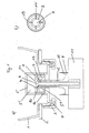
- the dispensing apparatus shown in Fig. 1a) is equipped with a reservoir 1 in the form of a contractible storage bottle, which is mounted on a fixed receptacle 2 of the dispensing apparatus.
- a union nut 3 is screwed, which clamps an insert 4 in the opening of the reservoir 1 sealingly.
- the middle part of the insert 4 forms the bottom of a cylinder 5, which is arranged in the interior of the reservoir 1.
- a hollow piston 6 is arranged with a circumferential side wall, an upper end wall and a bottom.
- the cylinder 5 is subdivided into an upper chamber 5 'and a lower chamber 5 ".
- a central opening 6a is located in the upper end wall of the hollow piston 6.
- the upper part of an outer auxiliary pipe 7 is arranged The upper end of the outer auxiliary tube 7 has an opening 7a
- the upper part of an inner application tube 8 is arranged, which has a circumferential tube wall, an upper, closed end and a lower, open end, wherein in the upper part of the tube wall of the inner application tube 8, a plurality of openings 8a are provided transversely to the longitudinal direction, which are covered in the illustrated case by the outer auxiliary tube 7.
- the cylinder has openings 5a in its side wall, which are arranged near the ground and are covered by the side wall of the hollow piston 6 in the illustrated case.
- the lower part of the application tube 8, which protrudes from the outer auxiliary tube 7, is connected to a receiving disc 9, which in turn is connected via retaining clips 10 with a movable part 11 of the dispensing apparatus.
- the receiving disc 9 is formed such that between its upper end and the lower end of the outer auxiliary tube 7, a distance 12 remains, which defines an inner stroke.
- the lower end of the inner application tube 8 is freely connected to the environment.
- the outer auxiliary tube 7 supports a projection 13 at its upper end, which is an integral part of the hollow piston 6.
- This arrangement is shown schematically in Fig. 1b) from above.
- the stop means 13 has four webs 14 on which the projection of the outer auxiliary tube 7 rests, on which in turn a protruding element, likewise in the form of a projection at the upper end, of the inner application tube 8 is supported.
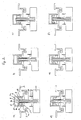
- Fig. 2a shows the rest state, in which the openings 5a are sealingly covered by the hollow piston 6, so that between the reservoir 1, which is not shown here, and the interior of the cylinder 5 no Fluid exchange is possible.
- the inner application tube 8 is in its closed position, so that the openings 8a, which represent the passage from the cylinder 5 to the application tube 8, are closed. So it is also no liquid discharge into the environment possible.
- Fig. 2b shows the state in which now the user operates the movable part 11 of the dispensing apparatus.
- the receiving disc 9 and consequently the associated application tube 8 moves upward until the upper end of the receiving disc 9 abuts against the lower end of the outer auxiliary tube 7.
- the inner application tube 8 has moved to its open position in which the openings 8a are free and a passage between the cylinder 5 and the environment is formed.
- the movable part 11 of the dispensing apparatus was further moved upward, so that the outer auxiliary tube 7 was moved from its lower end position upwards, since the receiving disk 9, the movement of the movable part 11 of the dispensing apparatus on the outer auxiliary tube transfers.
- the outer auxiliary tube 7 is located in the illustrated case in an intermediate position between the lower end position and the upper end position in which its upper end sealingly seals with the upper end wall of the hollow piston 6. At this time, therefore, the upper cylinder chamber 5 'is separated from the lower cylinder chamber 5 "such that no liquid can pass from the upper to the lower chamber.
- the openings 5a are no longer covered by the hollow piston 6, so that liquid is sucked from the reservoir 1 into the enlarged volume of the lower cylinder chamber 5 "by the negative pressure formed there, so that liquid is simultaneously sucked into the cylinder 5 and out of the cylinder 5 delivered to the environment.
- FIGS. 2e), f) and a) now show the sequence as soon as the user releases the dispensing apparatus.
- the movable part 11 of the dispensing apparatus moves down, which is achieved for example by a return spring, not shown, which acts directly or indirectly on the movable part 11 of the dispensing apparatus.
- the inner application tube 8 since it is connected via the receiving disk 9 and the brackets 10 with the movable part 11, moved downward.
- the upper chamber 5 'and the lower chamber 5 "of the cylinder 5 are still separated from each other.
- Fig. 2f shows that further down moving the movable part 11 of the dispensing apparatus and thus the inner application tube 8 and the outer auxiliary tube 7 is caused to move from its upper end position to its lower end position, wherein in Fig. 2f) the intermediate position and in Fig. 2a), the lower end position is shown.
- This is effected by providing a projection at the upper end of the application tube 8, which cooperates with a stop means, a chamfered phase, at the upper end of the outer auxiliary tube.
- the hollow piston 6 in that the hollow piston 6 is returned to its lower end position.
- the hollow piston 6 comprises a stop means 13 which cooperates with the projecting element of the outer auxiliary tube 7 and transmits the movement of the outer auxiliary tube to the remaining hollow body 6. Since the opening 6a in the upper end wall of the hollow piston 6 is opened by the return of the outer auxiliary tube 7 and the hollow piston 6, once it is in its lower position, the openings 5a in the cylinder 5 to the reservoir 1 closes again, the in the lower cylinder chamber 5 "distributed liquid evenly throughout the cylinder 5. A backflow into the reservoir 1 is not possible.
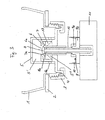
- FIG. 3 shows a dispensing apparatus and a pump according to the principle as described above, with the difference that the receiving disk 9 is divided into an upper part 9a and a lower part 9b.
- the upper part 9a forms a device with which the distance 12 between the upper end of the Receptacle 9 and the lower end of the outer auxiliary tube 7 is changeable when the inner application tube 8 is in the closed position, ie in the case in which the distance 12 between the receiving plate 9 and auxiliary tube 7 is maximum.
- the upper part 9a is threadedly connected to the lower part 9b, so that the upper part 9a can be turned relative to the lower part 9b. If the part 9a is turned upwards relative to the part 9b, the distance 12 is reduced. This has the advantage that the inner stroke and thus the delivery quantity of liquid soap can be adjusted.
- FIG. 4 shows two further exemplary embodiments of a pump according to the invention, which comprise as a special feature a return spring 15 or 16 integrated into the pump.
- a return spring 15 is provided, which is arranged around the outer auxiliary tube 7 and is supported on one side on the outside of the insert 4 and on the other side on the receiving plate 9. Since the receiving disk 9, which is firmly connected to the inner application tube 8 is, relative to the insert 4 is movable, which is fixedly connected to the cylinder 5, the return spring 15 acts in this case indirectly on the inner application tube 8 a.
- the return spring 15 allows the movement to take place automatically starting from the state shown in FIG. 2d) up to the state shown in FIG. 2a).
- the openings 5a are closed in the side wall of the cylinder 5 after a pumping operation by the pump's own return spring 15 acts indirectly on the inner application tube 8 and an overlap of the openings 5a through the side wall of the hollow piston 6, with the inner application tube 8 via the outer auxiliary tube 7 is in operative connection, forced.
- FIG. 4b The principle described above is also the basis of the embodiment of FIG. 4b), in which a return spring 16 is provided, which is arranged in the interior of the cylinder 5 and to one side on the inside of the cylinder 5 and the other side at the inner Application tube 8 is supported.
- the return spring 16 acts directly on the inner application tube 8 and also allows the movement to take place automatically, starting from the state shown in FIG. 2d) up to the state shown in FIG. 2a).
Abstract
Description
Die vorliegende Erfindung betrifft eine Pumpe zur Entnahme von Flüssigkeit oder pastöser Masse, insbesondere flüssiger Seife, Cremes, Desinfektionsmitteln, Lebensmitteln, oder anderer fließfähiger Substanzen, aus einem Reservoir, insbesondere einem kontraktionsfähigen Vorratsbehälter, sowie einen entsprechenden Spendeapparat und ein entsprechendes Verfahren zur Entnahme von Flüssigkeit oder pastöser Masse.The present invention relates to a pump for removing liquid or pasty mass, in particular liquid soap, creams, disinfectants, foods, or other flowable substances from a reservoir, in particular a contractible storage container, and a corresponding dispensing apparatus and a corresponding method for removing liquid or pasty mass.
Derartige Pumpen bzw. Spendeapparate sind in einer Vielzahl von Ausgestaltungen bekannt wie zum Beispiel aus
Daraufhin wurden Pumpen entwickelt, welche ausschließlich aus Kunststoffteilen zusammengesetzt sind. So offenbart die
Die bekannte Pumpe hat allerdings den Nachteil, dass das Rückschlagventil im Laufe der Zeit seine Dichtwirkung verliert, beispielsweise durch angetrocknete Seifenreste im Bereich der Ventilklappe. Im übrigen handelt es sich bei einem ausschließlich aus Kunststoff gefertigten Rückschlagventil um ein relativ elastisches Bauteil, was die Dichtwirkung ebenfalls negativ beeinflusst. Sobald die Dichtwirkung etwas nachläßt und der Flüssigkeitsstrom abreißt, strömt Umgebungsluft in das Reservoir. Die Folge ist, dass im Reservoir, es handelt sich dabei in der Regel um einen kontraktionsfähigen Vorratsbehälter, kein genügendes Vakuum aufgebaut werden kann. Das Vakuum ist aber zwingend für ein optimales Funktionieren der Rückschlagventile erforderlich. Außerdem läßt sich der Behälter nicht optimal zusammendrücken, so dass folglich die Flüssigseife nicht vollständig herausgesaugt werden kann. Dadurch, dass sich mit der bekannten Pumpe das Reservoir nicht optimal zusammendrücken läßt, verbleibt regelmäßig eine nicht nutzbare Restmenge von 5 bis 20% des ursprünglichen Inhalts im Reservoir.However, the known pump has the disadvantage that the non-return valve loses its sealing effect over time, for example due to dried soap residue in the region of the valve flap. Incidentally, it is a non-return valve made entirely of plastic to a relatively elastic component, which also adversely affects the sealing effect. As soon as the sealing action subsides somewhat and the liquid flow breaks off, ambient air flows into the reservoir. The result is that in the reservoir, it is usually a contraction-capable reservoir, no sufficient vacuum can be built. The vacuum is mandatory for optimal functioning of the check valves required. In addition, the container can not be optimally compressed, so that consequently the liquid soap can not be completely sucked out. Because the reservoir can not be optimally compressed with the known pump, a non-usable residual amount of 5 to 20% of the original content in the reservoir regularly remains.
Es sind aber auch Weiterentwicklungen der zuvor beschriebenen Pumpe bekannt, die auf ein Rückschlagventil vollständig verzichten. So offenbart die
Die zuvor beschriebene Pumpe hat zwar kein Rückschlagventil mehr, dafür aber mehrere elastische Dichtelemente. Diese Dichtelemente haben ebenfalls den Nachteil, dass sie im Laufe der Zeit ihre Dichtwirkung verlieren, insbesondere wenn das zu pumpende Produkt im Bereich der Dichtelemente angetrocknet ist, so dass auch hier Restmengen ungenutzt im Reservoir verbleiben. Je grobkörniger im übrigen das zu pumpende Produkt bzw. seine Beimischungen sind, um so größer ist die verbleibende Restmenge.Although the previously described pump no longer has a check valve, it does have several elastic sealing elements. These sealing elements also have the disadvantage that they lose their sealing effect over time, especially when the product to be pumped in the Area of the sealing elements is dried, so that even here remain unused residues in the reservoir. The coarser-grained, moreover, the product to be pumped or its admixtures, the greater the remaining amount.
Ausgehend von dem zuvor beschriebenen Stand der Technik liegt der vorliegenden Erfindung die Aufgabe zugrunde, eine Pumpe zur Entnahme von Flüssigkeit oder pastöser Masse, insbesondere flüssiger Seife, sowie einen entsprechenden Spendeapparat und ein entsprechendes Verfahren bereitzustellen, womit eine verbesserte Dichtwirkung erzielbar ist und womit die verbleibende Restmenge im Reservoir reduzierbar ist.Based on the above-described prior art, the present invention seeks to provide a pump for removing liquid or pasty mass, in particular liquid soap, and a corresponding dispensing apparatus and a corresponding method, whereby an improved sealing effect can be achieved and what the remaining Residual amount in the reservoir is reducible.
Erfindungsgemäß ist die zuvor hergeleitete und aufgezeigte Aufgabe gelöst durch eine Pumpe zur Entnahme von Flüssigkeit oder pastöser Masse, insbesondere flüssiger Seife, aus einem Reservoir, insbesondere einem kontraktionsfähigen Vorratsbehälter, umfassend einen Zylinder, einen innerhalb des Zylinders angeordneten Hohlkolben, ein zumindest teilweise innerhalb des Hohlkolbens angeordnetes äußeres Hilfsrohr und ein zumindest teilweise innerhalb des äußeren Hilfsrohrs angeordnetes inneres Applikationsrohr, wobei das innere Applikationsrohr relativ zum äußeren Hilfsrohr bewegbar ist und derart mit dem äußeren Hilfsrohr zusammenwirkt, dass eine Bewegung des inneren Applikationsrohrs eine Bewegung des äußeren Hilfsrohrs bewirkt, wobei das äußere Hilfsrohr relativ zum Hohlkolben bewegbar ist und derart mit dem Hohlkolben zusammenwirkt, dass eine Bewegung des äußeren Hilfsrohrs eine Bewegung des Hohlkolbens bewirkt, wobei der Hohlkolben relativ zum Zylinder bewegbar ist, wobei im Zylinder mindestens eine Öffnung vorgesehen ist, die den Raum innerhalb des Reservoirs mit dem Raum innerhalb des Zylinders verbinden kann und die vom Hohlkolben geöffnet und geschlossen werden kann, wobei im Hohlkolben eine Öffnung vorgesehen ist, die vom inneren Applikationsrohr zusammen mit dem äußeren Hilfsrohr geöffnet und geschlossen werden kann, wobei im äußeren Hilfsrohr eine Öffnung vorgesehen ist, die vom inneren Applikationsrohr geöffnet und geschlossen werden kann, wobei im inneren Applikationsrohr mindestens eine Öffnung vorgesehen ist, die vom äußeren Hilfsrohr geöffnet und geschlossen werden kann, derart, dass Flüssigkeit oder pastöse Masse gleichzeitig vom Zylinder durch das innere Applikationsrohr in die Umgebung abgegeben und vom Reservoir in den Zylinder gesaugt werden kann.According to the invention, the previously derived and indicated object is achieved by a pump for removing liquid or pasty mass, in particular liquid soap, from a reservoir, in particular a contractible supply container, comprising a cylinder, a hollow piston arranged inside the cylinder, at least partially within the hollow piston disposed outer auxiliary tube and disposed at least partially within the outer auxiliary tube inner application tube, wherein the inner application tube is movable relative to the outer auxiliary tube and cooperates with the outer auxiliary tube such that movement of the inner application tube causes movement of the outer auxiliary tube, wherein the outer auxiliary tube is movable relative to the hollow piston and cooperates with the hollow piston such that a movement of the outer auxiliary tube causes a movement of the hollow piston, wherein the hollow piston is movable relative to the cylinder, wherein at least one opening is provided in the cylinder, which can connect the space within the reservoir with the space inside the cylinder and which can be opened and closed by the hollow piston, wherein in the hollow piston an opening is provided which can be opened and closed by the inner application tube together with the outer auxiliary tube, wherein in the outer Auxiliary tube is provided an opening which can be opened and closed by the inner application tube, wherein at least one opening is provided in the inner application tube, which can be opened and closed by the outer auxiliary tube, such that liquid or pasty mass simultaneously from the cylinder through the inner application tube discharged into the environment and can be sucked from the reservoir into the cylinder.
Dabei beziehen sich alle Angaben zu Bewegungen und Positionen wie oben, unten etc. auf die Längsrichtung der Pumpe, das heißt die Richtung, in der das zu entnehmende flüssige oder pastöse Medium - im folgenden der Einfachheit halber als Flüssigkeit bezeichnet - aus dem Zylinder durch das Applikationsrohr in die Umgebung, also den Bereich außerhalb des Spendeapparats, gelangt.In this case, all information on movements and positions such as above, below, etc. refer to the longitudinal direction of the pump, that is, the direction in which the liquid or pasty medium to be removed - hereinafter referred to as liquid for simplicity - from the cylinder through the Application tube into the environment, ie the area outside the dispensing apparatus, passes.
Die erfindungsgemäße Pumpe kommt erstmalig ganz ohne Rückschlagventil und elastische Dichtlippen aus, verzichtet also auf die Teile, die im Stand der Technik die Dichtwirkung und damit den Aufbau des Vakuums im Reservoir negativ beeinflussen. Außerdem unterscheidet sich diese Pumpe vom Stand der Technik dadurch, dass gleichzeitig mit Abgabe der Flüssigkeit aus dem Zylinder an die Umgebung neue Flüssigkeit aus dem Reservoir in den Zylinder gesaugt wird, also erfindungsgemäß eine Selbstansaugung realisiert wird. Die vorliegende Erfindung ermöglicht eine optimale Evakuierung des Reservoirs und eine Reduzierung der schließlich verbleibenden Restmenge an Flüssigkeit.For the first time, the pump according to the invention is completely without a check valve and elastic sealing lips, and thus dispenses with the parts which, in the prior art, adversely affect the sealing effect and thus the build-up of the vacuum in the reservoir. In addition, this pump differs from the prior art in that simultaneously with the discharge of the liquid from the cylinder to the environment new liquid from the reservoir is sucked into the cylinder, so according to the invention a self-suction is realized. The present invention enables optimal evacuation of the Reservoirs and a reduction of the remaining remaining amount of liquid.
Vorteilhafterweise ist der einen Zylinder mit einer umlaufenden Seitenwand, einer oberen Stirnwand und einem Boden versehen.Advantageously, the one cylinder is provided with a circumferential side wall, an upper end wall and a bottom.
Vorteilhafterweise ist der Hohlkolben, der innerhalb des Zylinders angeordnet ist, mit einer umlaufenden Seitenwand, einer oberen Stirnwand und einem Boden versehen.Advantageously, the hollow piston, which is arranged within the cylinder, provided with a circumferential side wall, an upper end wall and a bottom.
Vorteilhafterweise ist das äußere Hilfsrohr, das zumindest teilweise innerhalb des Hohlkolbens angeordnet ist, mit einer umlaufenden Rohrwand, einem oberen, offenen Ende und einem unteren, offenen Ende versehen.Advantageously, the outer auxiliary tube, which is at least partially disposed within the hollow piston, provided with a circumferential tube wall, an upper, open end and a lower, open end.
Vorteilhafterweise ist das innere Applikationsrohr, das zumindest teilweise innerhalb des äußeren Hilfsrohrs angeordnet ist, mit einer umlaufenden Rohrwand, einem oberen, geschlossenen Ende und einem unteren, offenen Ende versehen, wobei im oberen Teil der Rohrwand quer zur Längsrichtung mindestens eine Öffnung angeordnet ist.Advantageously, the inner application tube, which is at least partially disposed within the outer auxiliary tube, provided with a circumferential tube wall, an upper, closed end and a lower, open end, wherein at least one opening is arranged transversely to the longitudinal direction in the upper part of the tube wall.
Gemäß einer bevorzugten Ausgestaltung ist der Zylinder in eine obere und eine untere Kammer unterteilt, wobei die obere Kammer als der Raum zwischen der oberen Stirnwand des Zylinders und der oberen Stirnwand des Hohlkolbens und die untere Kammer als der Raum zwischen der oberen Stirnwand des Hohlkolbens und dem Boden des Zylinders definiert ist, wobei der Zylinder eine Öffnung im Boden, durch die das äußere Hilfsrohr von der Umgebung ins Innere des Zylinders verläuft, und eine oder mehrere Öffnungen in einem Bereich aufweist, der innenseitig vom Hohlkolben überdeckbar ist.According to a preferred embodiment, the cylinder is divided into an upper and a lower chamber, wherein the upper chamber as the space between the upper end wall of the cylinder and the upper end wall of the hollow piston and the lower chamber as the space between the upper end wall of the hollow piston and the Bottom of the cylinder is defined, wherein the cylinder has an opening in the bottom, through which the outer auxiliary tube from the environment into the interior of the cylinder, and one or more Having openings in a region which is covered on the inside of the hollow piston.
Gemäß einer weiteren Ausgestaltung ist der Hohlkolben im Zylinder beweglich gelagert und die Seitenwand des Hohlkolbens in abdichtender, gleitender Verbindung mit der Seitenwand des Zylinders, wobei der Hohlkolben bewegbar ist zwischen einer unteren Endposition, in der die Öffnungen im Zylinder in dem innenseitig vom Hohlkolben überdeckbaren Bereich abdichtend überdeckt sind, und einer oberen Endposition, in der die Öffnungen im Zylinder in dem innenseitig vom Hohlkolben überdeckbaren Bereich frei sind, wobei der Hohlkolben mindestens eine Öffnung im Boden aufweist sowie eine Öffnung in der oberen Stirnwand.According to a further embodiment, the hollow piston is movably mounted in the cylinder and the side wall of the hollow piston in sealing, sliding connection with the side wall of the cylinder, wherein the hollow piston is movable between a lower end position in which the openings in the cylinder in the inside of the hollow piston coverable area are sealingly covered, and an upper end position in which the openings in the cylinder in the inside of the hollow piston can be covered over area, wherein the hollow piston has at least one opening in the bottom and an opening in the upper end wall.
Gemäß noch einer bevorzugten Ausgestaltung ist das äußere Hilfsrohr in der Öffnung im Boden des Zylinders beweglich gelagert und die Rohrwand des äußeren Hilfsrohrs in abdichtender, gleitender Verbindung mit der Öffnung im Boden des Zylinders, wobei das äußere Hilfsrohr bewegbar ist zwischen einer unteren Endposition, in der das obere Ende des äußeren Hilfsrohrs beabstandet zur oberen Stirnwand des Hohlkolbens liegt, und einer oberen Endposition, in der das obere Ende des äußeren Hilfsrohrs mit der oberen Stirnwand des Hohlkolbens abdichtend abschließt, wobei eine Zwischenposition zwischen der unteren Endposition und der oberen Endposition definiert ist, in der das obere Ende des äußeren Hilfsrohrs mit der oberen Stirnwand des Hohlkolbens abdichtend abschließt, wenn der Hohlkolben in der unteren Endposition ist, und beabstandet zur oberen Stirnwand des Hohlkolbens liegt, wenn der Hohlkolben in der oberen Endposition ist, wobei ein vorspringendes Element am äußeren Hilfsrohr vorgesehen ist, das mit einem Teil des Hohlkolbens zusammenwirkt .According to yet a preferred embodiment, the outer auxiliary tube is movably supported in the opening in the bottom of the cylinder and the tube wall of the outer auxiliary tube in sealing, sliding connection with the opening in the bottom of the cylinder, wherein the outer auxiliary tube is movable between a lower end position, in the the upper end of the outer auxiliary tube being spaced from the upper end wall of the hollow piston, and an upper end position sealingly closing the upper end of the outer auxiliary tube with the upper end wall of the hollow piston defining an intermediate position between the lower end position and the upper end position; in which the upper end of the outer auxiliary tube sealingly closes with the upper end wall of the hollow piston when the hollow piston is in the lower end position, and spaced from the upper end wall of the hollow piston, when the hollow piston is in the upper end position, wherein a protruding element on the outer H ilfsrohr is provided, which cooperates with a part of the hollow piston.
Gemäß einer weiteren bevorzugten Ausgestaltung ist das innere Applikationsrohr im äußeren Hilfsrohr beweglich gelagert und die Rohrwand des inneren Applikationsrohrs in abdichtender, gleitender Verbindung mit der Rohrwand des äußeren Hilfsrohrs, wobei das innere Applikationsrohr relativ zum äußeren Hilfsrohr bewegbar ist zwischen einer geschlossenen Lage, in der die Öffnung in der Rohrwand des inneren Applikationsrohrs durch das obere Ende der Rohrwand des äußeren Hilfsrohrs abdichtend überdeckt ist, und einer geöffneten Lage, in der die Öffnung in der Rohrwand des inneren Applikationsrohrs frei ist, wobei der Durchmesser des oberen Endes des inneren Applikationsrohrs kleiner als der Durchmesser der Öffnung in der oberen Stirnwand des Hohlkolbens ist und wobei ein vorspringendes Element am inneren Applikationsrohr vorgesehen ist, das mit einem Teil des äußeren Hilfsrohrs zusammenwirkt .According to a further preferred embodiment, the inner application tube is movably mounted in the outer auxiliary tube and the tube wall of the inner application tube in sealing, sliding connection with the tube wall of the outer auxiliary tube, wherein the inner application tube is movable relative to the outer auxiliary tube between a closed position in which Opening in the tube wall of the inner application tube is sealingly covered by the upper end of the tube wall of the outer auxiliary tube, and an open position in which the opening in the tube wall of the inner application tube is free, wherein the diameter of the upper end of the inner application tube is smaller than that Diameter of the opening in the upper end wall of the hollow piston and wherein a projecting element is provided on the inner application tube, which cooperates with a part of the outer auxiliary tube.
Gemäß einer weiteren bevorzugten Ausgestaltung ist eine Aufnahmescheibe zur Verbindung mit dem beweglichen Teil eines Spendeapparates vorgesehen, die mit dem inneren Applikationsrohr verbunden ist und so weit unterhalb des unteren Endes des äußeren Hilfsrohrs angeordnet ist, dass zwischen dem oberen Ende der Aufnahmescheibe und dem unteren Ende des äußeren Hilfsrohrs ein Abstand vorgesehen ist, wenn das innere Applikationsrohr in der geschlossenen Lage ist, und das obere Ende der Aufnahmescheibe und das untere Ende des äußeren Hilfsrohrs einander berühren, wenn das innere Applikationsrohr in der geöffneten Lage ist.According to a further preferred embodiment, a receiving disc for connection to the movable part of a dispensing apparatus is provided, which is connected to the inner application tube and is disposed so far below the lower end of the outer auxiliary tube that between the upper end of the receiving disc and the lower end of the outer auxiliary tube, a distance is provided when the inner application tube is in the closed position, and the upper end of the receiving disc and the lower end of the outer auxiliary tube touch each other when the inner application tube is in the open position.
Gemäß einer vorteilhaften Ausgestaltung der erfindungsgemäßen Pumpe ist der Boden des Zylinders Bestandteil eines Einlegeteils, das das Reservoir gegenüber der Umgebung abdichtend verschließen kann. Außerdem kann vorgesehen sein, dass die Öffnungen im Zylinder in dem Bereich, der innenseitig vom Hohlkolben überdeckbar ist, in der Seitenwand des Zylinders angeordnet sind. Vorzugsweise befinden sich diese Öffnungen in Bodennähe.According to an advantageous embodiment of the pump according to the invention, the bottom of the cylinder is part of an insert, which can seal the reservoir against the environment sealing. In addition, it can be provided that the openings in the cylinder in the region which can be covered on the inside by the hollow piston, are arranged in the side wall of the cylinder. Preferably, these openings are near the floor.
Es kann gemäß einer weiteren vorteilhaften Ausgestaltung vorgesehen sein, dass der Hohlkolben in seiner unteren Endposition den Boden des Zylinders berührt. Dadurch wird, in Verbindung mit dem vorspringenden Element am äußeren Hilfsrohr, das mit einem Teil des Hohlkolbens zusammenwirkt, die untere Endposition des äußeren Hilfsrohrs definiert, da der Hohlkolben am Zylinderboden einen Anschlag erfährt. Außerdem kann vorgesehen sein, dass der Durchmesser der Öffnung im Boden des Hohlkolbens gleich dem Innendurchmesser des Hohlkolbens ist. Auf diese Weise ist der Boden allein durch die untere Kante der Seitenwand des Hohlkolbens gebildet, was eine Materialersparnis mit sich bringt.It may be provided according to a further advantageous embodiment that the hollow piston touches the bottom of the cylinder in its lower end position. Thereby, in conjunction with the protruding element on the outer auxiliary tube, which cooperates with a part of the hollow piston, defines the lower end position of the outer auxiliary tube, since the hollow piston undergoes a stop on the cylinder bottom. In addition, it can be provided that the diameter of the opening in the bottom of the hollow piston is equal to the inner diameter of the hollow piston. In this way, the bottom is formed solely by the lower edge of the side wall of the hollow piston, which brings a saving of material with it.
Gemäß einer weiteren vorteilhaften Ausgestaltung kann das vorspringende Element am äußeren Hilfsrohr ein zumindest teilweise umlaufender Falz oder eine Auskragung sein. Entsprechendes gilt auch für das innere Applikationsrohr. Auch hier kann ein umlaufender Falz oder eine Auskragung als vorspringendes Element vorgesehen sein. Der mit dem vorspringenden Element zusammenwirkende Teil des Hohlkolbens kann ein Anschlagmittel sein, das insbesondere mit der Seitenwand des Hohlkolbens verbunden ist. Der mit dem vorspringenden Element zusammenwirkende Teil des Hohlkolbens kann aber auch die obere Stirnwand oder der Boden des Hohlkolbens sein. Auf jeden Fall muss garantiert sein, dass das vorspringende Element des äußeren Hilfsrohrs bewirkt, dass der Hohlkolben sowohl nach oben als auch nach unten mitbewegt werden kann. Entsprechend muss auch gewährleistet sein, dass das vorspringende Element des inneren Applikationsrohrs derart mit dem äußeren Hilfsrohr zusammenwirkt, dass das äußere Hilfsrohr durch eine nach unten gerichtete Bewegung des inneren Applikationsrohrs ebenfalls nach unten bewegt wird.According to a further advantageous embodiment, the projecting element on the outer auxiliary tube may be an at least partially circumferential fold or a projection. The same applies to the inner application tube. Again, a circumferential fold or a projection may be provided as a projecting element. The cooperating with the projecting element part of the hollow piston may be a stop means, in particular connected to the side wall of the hollow piston is. However, the cooperating with the projecting element part of the hollow piston may also be the upper end wall or the bottom of the hollow piston. In any case, it must be guaranteed that the protruding element of the outer auxiliary tube causes the hollow piston can be moved both up and down. Accordingly, it must also be ensured that the projecting element of the inner application tube cooperates with the outer auxiliary tube such that the outer auxiliary tube is also moved downward by a downward movement of the inner application tube.
Vorteilhafterweise weist das Anschlagmittel, welches den mit dem vorspringenden Element am äußeren Hilfsrohr zusammenwirkenden Teil des Hohlkolbens darstellt, einen oder mehrere Stege oder aber einen Ring mit Durchlässen auf, wobei die Durchlässe den Bereich oberhalb des Anschlagmittels mit dem Bereich unterhalb des Anschlagmittels verbinden. Auf diese Weise ist zu jedem Zeitpunkt, insbesondere wenn bei einer nach unten gerichteten Bewegung das vorspringende Element auf dem Anschlagmittel aufliegt, eine Verbindung und damit ein Austausch der Flüssigkeit zwischen unterer und oberer Zylinderkammer gewährleistet.Advantageously, the stop means, which represents the cooperating with the protruding element on the outer auxiliary tube part of the hollow piston, one or more webs or a ring with passages, wherein the passages connect the area above the stop means with the area below the stop means. In this way, at any time, especially when in a downward movement, the projecting element rests on the stop means, a connection and thus an exchange of liquid between the lower and upper cylinder chamber guaranteed.
Gemäß noch einer weiteren vorteilhaften Ausgestaltung der erfindungsgemäßen Pumpe ist vorgesehen, dass die Aufnahmescheibe eine Einrichtung aufweist, mit der der Abstand zwischen dem oberen Ende der Aufnahmescheibe und dem unteren Ende des äußeren Hilfsrohrs veränderbar ist, wenn das innere Applikationsrohr in der geschlossenen Lage ist, also in dem Fall, in dem der Abstand zwischen Aufnahmescheibe und Hilfsrohr maximal ist. Dies hat den Vorteil, dass der innere Hub und damit die Abgabemenge einstellbar ist und zwar unabhängig vom externen Hub des beweglichen Teils des Spendeapparates, der immer gleich bleibt. Je kleiner der maximale Abstand zwischen dem oberen Ende der Aufnahmescheibe und dem unteren Ende des äußeren Hilfsrohrs eingestellt wird, um so weiter drückt das äußere Hilfsrohr den Hohlkolben nach oben und um so mehr Flüssigkeit wird aus der oberen Zylinderkammer durch das Applikationsrohr herausgedrückt.According to yet another advantageous embodiment of the pump according to the invention it is provided that the receiving disc has a device with which the distance between the upper end of the receiving disc and the lower end of the outer auxiliary tube is changeable when the inner application tube is in the closed position, ie in the case where the distance between the pickup disk and the auxiliary pipe is maximum. This has the Advantage that the inner stroke and thus the discharge amount is adjustable, regardless of the external stroke of the moving part of the dispensing apparatus, which always remains the same. The smaller the maximum distance between the upper end of the receiving disk and the lower end of the outer auxiliary pipe is adjusted, the further the outer auxiliary pipe pushes the hollow piston upwards and the more liquid is forced out of the upper cylinder chamber through the application pipe.
Die den Abstand einstellende Einrichtung kann einen oberen Teil der Aufnahmescheibe bilden und mit einem unteren Teil der Aufnahmescheibe oder mit dem inneren Applikationsrohr derart beweglich verbunden sein, dass der Abstand zwischen dem unteren Teil der Aufnahmescheibe und dem oberen Teil der Aufnahmescheibe veränderbar ist. Wird also bei feststehendem unteren Teil der Aufnahmescheibe ihr oberer Teil in Richtung des unteren Endes des äußeren Hilfsrohrs bewegt, so verringert sich auch der Abstand zwischen oberem Ende der Aufnahmescheibe und unterem Ende des äußeren Hilfsrohrs.The spacing adjusting means may form an upper part of the receiving disk and be movably connected to a lower part of the receiving disk or to the inner application pipe such that the distance between the lower part of the receiving disk and the upper part of the receiving disk is changeable. Thus, when the upper part is moved towards the lower end of the outer auxiliary tube when the lower part of the receiving disc is stationary, the distance between the upper end of the receiving plate and the lower end of the outer auxiliary tube is also reduced.
Eine besonders einfache Bedienung dieser Verstelleinrichtung kann dadurch erreicht werden, dass der obere Teil der Aufnahmescheibe mit dem unteren Teil der Aufnahmescheibe oder mit dem inneren Applikationsrohr durch ein Gewinde verbunden ist, derart, dass ein Verdrehen des oberen Teils gegenüber dem unteren Teil der Aufnahmescheibe bzw. ein Verdrehen des oberen Teils der Aufnahmescheibe gegenüber dem inneren Applikationsrohr zu einer Änderung des Abstands zwischen unterem Teil und oberem Teil der Aufnahmescheibe führt.A particularly simple operation of this adjusting device can be achieved in that the upper part of the receiving disk is connected to the lower part of the receiving disk or with the inner application pipe by a thread, such that a rotation of the upper part relative to the lower part of the receiving disk or a rotation of the upper part of the receiving disc relative to the inner application tube leads to a change in the distance between the lower part and the upper part of the receiving disc.
Gemäß noch einer weiteren vorteilhaften Ausgestaltung der erfindungsgemäßen Pumpe ist mindestens eine Rückholfeder vorgesehen, die direkt oder indirekt auf das innere Applikationsrohr einwirkt. Es ist auch denkbar, dass mehrere Rückholfedern direkt und/oder indirekt auf das innere Applikationsrohr einwirken. Gemäß Stand der Technik war bisher, um einen Pumpvorgang abzuschließen und die Pumpe in ihre Ruhestellung zurückzuführen, zwingend ein Spendeapparat mit eigener Rückholfeder erforderlich. Ist nun mindestens eine Rückholfeder in die Pumpe integriert oder bildet diese mit der Pumpe eine bauliche Einheit, wird ermöglicht, dass auch ohne die Verwendung eines Spendeapparates die Öffnungen in der Seitenwand des Zylinders nach einem Pumpvorgang automatisch geschlossen werden bzw. im Ruhezustand der Pumpe automatisch geschlossen bleiben, indem nämlich die pumpeneigene Rückholfeder auf das innere Applikationsrohr einwirkt und eine Überdeckung der Öffnungen durch die Seitenwand des Hohlkolbens, mit dem das innere Applikationsrohr über das äußere Hilfsrohr in Wirkverbindung steht, forciert.According to yet another advantageous embodiment of the pump according to the invention, at least one return spring is provided, which acts directly or indirectly on the inner application tube. It is also conceivable that several return springs act directly and / or indirectly on the inner application tube. According to the prior art, in order to complete a pumping operation and to return the pump to its rest position, a dispensing apparatus with its own return spring was previously required. Is now at least one return spring integrated into the pump or this forms a structural unit with the pump, it is possible that even without the use of a dispensing apparatus, the openings in the side wall of the cylinder are automatically closed after a pumping or automatically closed in the idle state of the pump remain, namely by the pump's own return spring acts on the inner application tube and an overlap of the openings through the side wall of the hollow piston, with which the inner application tube via the outer auxiliary tube is in operative connection, forced.
Eine solche bauliche Einheit ist besonders als Verschluss eines Reservoirs für Flüssigkeit oder pastöse Masse geeignet. Wird eine mit einer Rückholfeder versehene Pumpe in bzw. auf die Öffnung eines Reservoirs gesetzt, beispielsweise mit dem Reservoir verschraubt oder verschweißt, kann das Reservoir auch unabhängig von einem Spendeapparat verwendet oder gelagert werden.Such a structural unit is particularly suitable as a closure of a reservoir for liquid or pasty mass. If a pump provided with a return spring is placed in or onto the opening of a reservoir, for example screwed or welded to the reservoir, the reservoir can also be used or stored independently of a dispensing apparatus.
Wird die Pumpe und/oder das Reservoir mit einer einfachen Befestigungseinrichtung wie einer Halterungsnut versehen, können anstatt eines komplex aufgebauten Spendeapparates relativ einfach aufgebaute und entsprechend kostengünstige Wandhalterungen oder dergleichen zur Aufbewahrung des Reservoirs verwendet werden. In besonderem Maße eignet sich eine solche Einheit aus Pumpe und Reservoir als Lebensmittelverpackung, beispielsweise für Mayonnaise, Ketchup, Senf oder dergleichen.If the pump and / or the reservoir is provided with a simple fastening device such as a retaining groove, instead of a complexly constructed dispensing apparatus, it is relatively easy to construct and correspondingly inexpensive wall brackets or the like can be used to store the reservoir. Such a unit of pump and reservoir is particularly suitable as food packaging, for example for mayonnaise, ketchup, mustard or the like.
Die Funktionsweise der Pumpe in Verbindung mit einem entsprechenden Reservoir und einem entsprechenden Spendeapparat ist die folgende:
- Im Ruhezustand sind die Öffnungen, die den Zylinderinnenraum mit dem Reservoir verbinden, durch den Hohlkolben innenseitig abdichtend überdeckt, so dass zwischen Reservoir und Zylinder kein Flüssigkeitsaustausch möglich ist. Gleichzeitig befindet sich das innere Applikationsrohr in seiner geschlossenen Lage, so dass der Durchgang vom Zylinderinnenraum durch das Applikationsrohr in die Umgebung geschlossen ist.
- Sobald nun der Benutzer den beweglichen Teil des Spendeapparates bedient, verlagert sich die Aufnahmescheibe und damit das innere Applikationsrohr solange nach oben, bis das obere Ende der Aufnahmescheibe an das untere Ende des äußeren Hilfsrohrs stößt. Dadurch hat sich das innere Applikationsrohr in seine geöffnete Lage begeben, wodurch der Durchgang zwischen Zylinder und Umgebung frei geworden ist.
- Wird das bewegliche Teil des Spendeapparates weiter nach oben bewegt, so wird dadurch auch das äußere Hilfsrohr aus seiner untere Endposition nach oben bewegt, da die Aufnahmescheibe die Bewegung des beweglichen Teils des Spendeapparates auf das äußere Hilfsrohr überträgt. Das äußere Hilfsrohr wird zunächst in eine Zwischenposition zwischen unterer Endposition und oberer Endposition bewegt, in der sein oberes Ende mit der oberen Stirnwand des Hohlkolbens abdichtend abschließt. Zu diesem Zeitpunkt ist dann die obere Zylinderkammer von der unteren Zylinderkammer derart getrennt, dass keine Flüssigkeit von der oberen in die untere Kammer gelangen kann.
- Wird der bewegliche Teil des Spendeapparates noch weiter nach oben bewegt, so drückt ein vorspringendes Element am äußeren Hilfsrohr, welches mit einem Teil des Hohlkolbens zusammenwirkt, den Hohlkolben von seiner unteren in seine obere Endposition. Dadurch wird das Volumen der oberen Kammer des Zylinders verringert, wodurch sich der Druck der Flüssigkeit erhöht. Dies führt dazu, dass die Flüssigkeit durch das nach wie vor in der geöffneten Lage befindliche Applikationsrohr ausströmt. Gleichzeitig werden die bisher vom Hohlkolben überdeckten Öffnungen, die den Zylinder mit dem Reservoir verbinden, freigegeben und das Volumen in der unteren Zylinderkammer vergrößert. Es entsteht ein Unterdruck in der unteren Kammer, der ein Ansaugen von Flüssigkeit aus dem Reservoir in die untere Kammer bewirkt. Es wird also gleichzeitig Flüssigkeit in den Zylinder gesaugt und aus dem Zylinder in die Umgebung abgegeben.
- Sobald nun der Benutzer den Spendeapparat los läßt und damit das bewegliche Teil des Spendeapparates dazu veranlasst, sich nach unten zu bewegen, wird zunächst das innere Applikationsrohr in seine geschlossene Lage gebracht. Bei weiterem Herunterbewegen des beweglichen Teils des Spendeapparates und damit des inneren Applikationsrohrs wird auch das äußere Hilfsrohr dazu veranlasst, sich von seiner oberen Endposition in seine untere Endposition zu bewegen. Während sich das äußere Hilfsrohr in die untere Endposition zurückbewegt, bewirkt dieses durch ein vorspringendes Element, welches mit dem Hohlkolben zusammenwirkt, dass auch der Hohlkolben in seine untere Endposition zurückgeführt wird. Da die Öffnung in der oberen Stirnwand des Hohlkolbens durch das Rückführen des äußeren Hilfsrohrs geöffnet wird und der Hohlkolben, sobald er in seiner unteren Endposition ist, die Öffnungen in dem Zylinder zum Reservoir hin wieder verschließt, kann sich die in der unteren Zylinderkammer befindliche Flüssigkeit gleichmäßig im Zylinder verteilen. Ein Zurückströmen in das Reservoir ist nicht möglich.
- Der zuvor beschriebene Ablauf wird dadurch optimiert, dass die Reibkräfte zwischen den einzelnen Bauteilen der Pumpe derart gewählt sind, dass eine Übertragung der Bewegung eines Bauteils auf das jeweils andere Bauteil nicht durch Reibkräfte bewirkt wird. So kann das innere Applikationsrohr von seiner geschlossenen Lage in seine geöffnete Lage bewegt werden, ohne dass sich dabei zwingend das äußere Hilfsrohr mitbewegt. Entsprechendes gilt auch für die gleitende Verbindung zwischen äußerem Hilfsrohr und Hohlkolben.
- In the idle state, the openings which connect the cylinder interior with the reservoir are sealed by the hollow piston on the inside, so that no fluid exchange between the reservoir and the cylinder is possible. At the same time, the inner application tube is in its closed position, so that the passage from the cylinder interior through the application tube into the environment is closed.
- Now, as soon as the user operates the moving part of the dispensing apparatus, the receiving disc and thus the inner application tube moves upward until the upper end of the receiving disc abuts the lower end of the outer auxiliary tube. As a result, the inner application tube has moved to its open position, whereby the passage between the cylinder and the environment has become free.
- If the movable part of the dispensing apparatus continues to move upwards, it also causes the outer auxiliary tube to be moved upwards from its lower end position, since the receiving disk controls the movement of the dispenser movable part of the dispensing apparatus transmits to the outer auxiliary tube. The outer auxiliary tube is first moved to an intermediate position between the lower end position and the upper end position, in which its upper end sealingly seals with the upper end wall of the hollow piston. At this time, the upper cylinder chamber is separated from the lower cylinder chamber so that no liquid can pass from the upper to the lower chamber.
- If the movable part of the dispensing apparatus is moved further upwards, a projecting element on the outer auxiliary tube, which cooperates with a part of the hollow piston, pushes the hollow piston from its lower end into its upper end position. This reduces the volume of the upper chamber of the cylinder, which increases the pressure of the liquid. As a result, the liquid flows out through the application tube, which is still in the open position. At the same time, the previously covered by the hollow piston openings that connect the cylinder to the reservoir, released and increases the volume in the lower cylinder chamber. The result is a negative pressure in the lower chamber, which causes a suction of liquid from the reservoir into the lower chamber. So it is simultaneously sucked liquid into the cylinder and discharged from the cylinder into the environment.
- As soon as the user lets go of the dispensing apparatus and thus causes the movable part of the dispensing apparatus to move downwards, first the inner application tube is in his closed position. Upon further downward movement of the movable part of the dispensing apparatus and thus of the inner application tube and the outer auxiliary tube is caused to move from its upper end position to its lower end position. While the outer auxiliary tube moves back into the lower end position, this causes by a projecting element, which cooperates with the hollow piston, that also the hollow piston is returned to its lower end position. Since the opening in the upper end wall of the hollow piston is opened by the return of the outer auxiliary tube and the hollow piston, once it is in its lower end position again closes the openings in the cylinder to the reservoir, the liquid in the lower cylinder chamber can be uniform distribute in the cylinder. A backflow into the reservoir is not possible.
- The procedure described above is optimized in that the frictional forces between the individual components of the pump are chosen such that a transmission of the movement of a component to the respective other component is not caused by frictional forces. Thus, the inner application tube can be moved from its closed position to its open position without necessarily moving the outer auxiliary tube. The same applies to the sliding connection between the outer auxiliary tube and hollow piston.
Die Aufgabe wird auch durch einen Spendeapparat zur Entnahme von Flüssigkeit, insbesondere flüssiger Seife, mit einer Pumpe gelöst, wie sie zuvor beschrieben wurde.The object is also achieved by a dispensing apparatus for removing liquid, in particular liquid soap, with a pump, as described above.
Schließlich wird die Aufgabe auch gelöst durch ein Verfahren zur Entnahme von Flüssigkeit oder pastöser Masse, insbesondere flüssiger Seife, mittels einer Pumpe mit den Merkmalen von Patentanspruch 23.Finally, the object is also achieved by a method for removing liquid or pasty mass, in particular liquid soap, by means of a pump having the features of patent claim 23.
Es gibt nun eine Vielzahl von Möglichkeiten, die erfindungsgemäße Pumpe, den Spendeapparat und das Verfahren auszugestalten und weiterzubilden. Hierzu wird beispielsweise verwiesen einerseits auf die dem Patentanspruch 1 nachgeordneten Patentansprüche, andererseits auf die Beschreibung eines Ausführungsbeispiels in Verbindung mit der Zeichnung. In der Zeichnung zeigt:
- Fig. 1a) und b)
- einen Spendeapparat zur Entnahme von Flüssigseife mit einer Pumpe gemäß einem ersten Ausführungsbeispiel der vorliegenden Erfindung;
- Fig. 2a) bis f)
- eine schematische Darstellung eines Pumpvorgangs bei dem Spendeapparat von Fig. 1;
- Fig. 3
- einen Spendeapparat zur Entnahme von Flüssigseife mit einer Pumpe gemäß einem zweiten Ausführungsbeispiel der vorliegenden Erfindung; und
- Fig. 4a) und b)
- einen Spendeapparat zur Entnahme von Flüssigseife mit einer Pumpe gemäß einem dritten und vierten Ausführungsbeispiel der vorliegenden Erfindung.
- Fig. 1a) and b)
- a dispenser for dispensing liquid soap with a pump according to a first embodiment of the present invention;
- Fig. 2a) to f)
- a schematic representation of a pumping operation in the dispensing apparatus of Fig. 1;
- Fig. 3
- a dispenser for dispensing liquid soap with a pump according to a second embodiment of the present invention; and
- Fig. 4a) and b)
- a dispenser for dispensing liquid soap with a pump according to a third and fourth embodiment of the present invention.
Der in Fig. 1a) dargestellte Spendeapparat ist mit einem Reservoir 1 in Form einer kontraktionsfähigen Vorratsflasche bestückt, welche auf einer festen Aufnahme 2 des Spendeapparates gelagert ist. Auf das offene Ende des Reservoirs 1 ist eine Überwurfmutter 3 aufgeschraubt, die ein Einlegeteil 4 in der Öffnung des Reservoirs 1 abdichtend festklemmt. Der mittlere Teil des Einlegeteils 4 bildet den Boden eines Zylinders 5, der im Innern des Reservoirs 1 angeordnet ist.The dispensing apparatus shown in Fig. 1a) is equipped with a
Innerhalb des Zylinders 5, der aus einer umlaufenden Seitenwand, einer oberen Stirnwand und dem genannten Boden besteht, ist ein Hohlkolben 6 mit einer umlaufenden Seitenwand, einer oberen Stirnwand und einem Boden angeordnet. Der Zylinder 5 ist unterteilt in eine obere Kammer 5' und eine untere Kammer 5". In der oberen Stirnwand des Hohlkolbens 6 befindet sich eine zentrale Öffnung 6a. Innerhalb des Hohlkolbens 6 ist wiederum der obere Teil eines äußeren Hilfsrohrs 7 angeordnet, das aus einer umlaufenden Rohrwand, einem oberen, offenen Ende und einem unteren, offenen Ende besteht. Das obere Ende des äußeren Hilfsrohrs 7 weist eine Öffnung 7a auf. Schließlich ist innerhalb des äußeren Hilfsrohrs 7 der obere Teil eines inneren Applikationsrohrs 8 angeordnet, das eine umlaufende Rohrwand, ein oberes, geschlossenes Ende und ein unteres, offenes Ende aufweist, wobei im oberen Teil der Rohrwand des inneren Applikationsrohrs 8 quer zur Längsrichtung mehrere Öffnungen 8a vorgesehen sind, die im dargestellten Fall vom äußeren Hilfsrohr 7 überdeckt sind. Auch der Zylinder weist Öffnungen 5a in seiner Seitenwand auf, die in Bodennähe angeordnet sind und im dargestellten Fall von der Seitenwand des Hohlkolbens 6 überdeckt sind.Within the
Der untere Teil des Applikationsrohrs 8, der aus dem äußeren Hilfsrohr 7 hinausragt, ist mit einer Aufnahmescheibe 9 verbunden, die wiederum über Halteklammern 10 mit einem beweglichen Teil 11 des Spendeapparats verbunden ist. Im dargestellten Fall ist die Aufnahmescheibe 9 derart ausgebildet, dass zwischen ihrem oberen Ende und dem unteren Ende des äußeren Hilfsrohrs 7 ein Abstand 12 verbleibt, der einen inneren Hub definiert.The lower part of the
Das untere Ende des inneren Applikationsrohrs 8 ist frei mit der Umgebung verbunden.The lower end of the
Im dargestellten Fall lagert das äußere Hilfsrohr 7 über eine Auskragung an seinem oberen Ende auf einem Anschlagmittel 13, das fester Bestandteil des Hohlkolbens 6 ist. Diese Anordnung ist schematisch in Fig. 1b) von oben dargestellt. Anhand dieser Darstellung erkennt man, dass das Anschlagmittel 13 vier Stege 14 aufweist, auf denen die Auskragung des äußeren Hilfsrohrs 7 lagert, auf der wiederum ein vorspringendes Element, ebenfalls in Form einer Auskragung am oberen Ende, des inneren Applikationsrohrs 8 lagert.In the illustrated case, the outer
Die Funktionsweise wird nun anhand der Figuren 2a) bis f) erläutert.The mode of operation will now be explained with reference to FIGS. 2a) to f).
Fig. 2a) zeigt den Ruhezustand, bei dem die Öffnungen 5a durch den Hohlkolben 6 abdichtend überdeckt sind, so dass zwischen dem Reservoir 1, das hier nicht dargestellt ist, und dem Innenraum des Zylinders 5 kein Flüssigkeitsaustausch möglich ist. Gleichzeitig befindet sich das innere Applikationsrohr 8 in seiner geschlossenen Lage, so dass die Öffnungen 8a, die den Durchgang vom Zylinder 5 zum Applikationsrohr 8 darstellen, geschlossen sind. Es ist also auch keine Flüssigkeitsabgabe in die Umgebung möglich.Fig. 2a) shows the rest state, in which the
Fig. 2b) zeigt den Zustand, in dem nun der Benutzer den beweglichen Teil 11 des Spendeapparates bedient. Sobald dies geschieht, verlagert sich die Aufnahmescheibe 9 und folglich das damit verbundene Applikationsrohr 8 solange nach oben, bis das obere Ende der Aufnahmescheibe 9 an das untere Ende des äußeren Hilfsrohrs 7 stößt. Dadurch hat sich das innere Applikationsrohr 8 in seine geöffnete Lage begeben, in der die Öffnungen 8a frei sind und ein Durchgang zwischen Zylinder 5 und Umgebung entsteht.Fig. 2b) shows the state in which now the user operates the
In Fig. 2c) wurde das bewegliche Teil 11 des Spendeapparates weiter nach oben bewegt, so dass auch das äußere Hilfsrohr 7 aus seiner unteren Endposition nach oben bewegt wurde, da die Aufnahmescheibe 9 die Bewegung des beweglichen Teils 11 des Spendeapparats auf das äußere Hilfsrohr 7 überträgt. Das äußere Hilfsrohr 7 befindet sich im dargestellten Fall in einer Zwischenposition zwischen unterer Endposition und oberer Endposition, in der sein oberes Ende mit der oberen Stirnwand des Hohlkolbens 6 abdichtend abschließt. Zu diesem Zeitpunkt ist also die obere Zylinderkammer 5' von der unteren Zylinderkammer 5" derart getrennt, dass keine Flüssigkeit von der oberen in die untere Kammer gelangen kann.In Fig. 2c), the
Wird nun der bewegliche Teil 11 des Spendeapparats, wie in Fig. 2d) dargestellt, noch weiter nach oben bewegt, so drückt eine Auskragung am äußeren Hilfsrohr 7, welche mit der oberen Stirnwand des Hohlkolbens 6 zusammenwirkt, den Hohlkolben 6 von seiner unteren in seine obere Endposition. Dadurch wird das Volumen der oberen Kammer 5' des Zylinders 5 verringert, wodurch sich der Druck der Flüssigkeit erhöht. Dies führt dazu, dass die Flüssigkeit durch das nach wie vor in der geöffneten Lage befindliche Applikationsrohr 8 ausströmt. Gleichzeitig sind die Öffnungen 5a nicht mehr vom Hohlkolben 6 überdeckt, so dass in das vergrößerte Volumen der unteren Zylinderkammer 5" durch den dort entstandenen Unterdruck Flüssigkeit aus dem Reservoir 1 gesaugt wird. Es wird also gleichzeitig Flüssigkeit in den Zylinder 5 gesaugt und aus dem Zylinder 5 in die Umgebung abgegeben.Now, if the
Die Figuren 2e), f) und a) zeigen nun den Ablauf, sobald der Benutzer den Spendeapparat wieder los läßt.FIGS. 2e), f) and a) now show the sequence as soon as the user releases the dispensing apparatus.
So bewegt sich, wie in Fig. 2e) dargestellt, zunächst der bewegliche Teil 11 des Spendeapparats nach unten, was beispielsweise durch eine nicht dargestellte Rückholfeder erreicht wird, die direkt oder indirekt auf den beweglichen Teil 11 des Spendeapparats einwirkt. Auch das innere Applikationsrohr 8 wird, da es über die Aufnahmescheibe 9 und die Klammern 10 mit dem beweglichen Teil 11 verbunden ist, nach unten bewegt. Zu diesem Zeitpunkt sind die obere Kammer 5' und die untere Kammer 5" des Zylinders 5 immer noch voneinander getrennt.Thus, as shown in Fig. 2e), first, the
Fig. 2f) zeigt, dass bei weiterem Herunterbewegen des beweglichen Teils 11 des Spendeapparats und damit des inneren Applikationsrohrs 8 auch das äußere Hilfsrohr 7 dazu veranlasst wird, sich von seiner oberen Endposition in seine untere Endposition zu bewegen, wobei in Fig. 2f) die Zwischenposition und in Fig. 2a) die untere Endposition gezeigt ist. Dies wird dadurch bewirkt, dass am oberen Ende des Applikationsrohrs 8 eine Auskragung vorgesehen ist, die mit einem Anschlagmittel, einer abgeschrägten Phase, am oberen Ende des äußeren Hilfsrohrs zusammenwirkt. Das vorspringende Element am äußeren Hilfsrohr 7, welches bereits gemäß den Figuren 2c) und d) den Hohlkolben 6 dazu veranlasst hat, sich nach oben zu bewegen, bewirkt nun, wie man anhand des Vergleiches von Fig. 2f) und Fig. 2a) erkennt, dass der Hohlkolben 6 in seine untere Endposition zurückgeführt wird. Dies geschieht dadurch, dass der Hohlkolben 6 ein Anschlagmittel 13 umfasst, welches mit dem vorspringende Element des äußeren Hilfsrohrs 7 zusammenwirkt und die Bewegung des äußeren Hilfsrohrs auf den übrigen Hohlkörper 6 überträgt. Da die Öffnung 6a in der oberen Stirnwand des Hohlkolbens 6 durch das Rückführen des äußeren Hilfsrohrs 7 geöffnet wird und der Hohlkolben 6, sobald er in seiner unteren Position ist, die Öffnungen 5a im Zylinder 5 zum Reservoir 1 hin wieder verschließt, kann sich die in der unteren Zylinderkammer 5" befindliche Flüssigkeit gleichmäßig im gesamten Zylinder 5 verteilen. Ein Zurückströmen in das Reservoir 1 ist nicht möglich.Fig. 2f) shows that further down moving the
Fig. 3 zeigt schließlich einen Spendeapparat und eine Pumpe nach dem Prinzip, wie es zuvor beschrieben wurde, mit dem Unterschied, dass die Aufnahmescheibe 9 in einen oberen Teil 9a und einen unteren Teil 9b aufgeteilt ist. Der obere Teil 9a bildet dabei eine Einrichtung, mit der der Abstand 12 zwischen dem oberen Ende der Aufnahmescheibe 9 und dem unteren Ende des äußeren Hilfsrohrs 7 veränderbar ist, wenn das innere Applikationsrohr 8 in der geschlossenen Lage ist, also in dem Fall, in dem der Abstand 12 zwischen Aufnahmescheibe 9 und Hilfsrohr 7 maximal ist.Finally, Fig. 3 shows a dispensing apparatus and a pump according to the principle as described above, with the difference that the
Der obere Teil 9a ist mit dem unteren Teil 9b über ein Gewinde verbunden, so dass der obere Teil 9a gegenüber dem unteren Teil 9b verdreht werden kann. Dreht man das Teil 9a gegenüber dem Teil 9b nach oben, so verringert sich der Abstand 12. Dies hat den Vorteil, dass der innere Hub und damit die Abgabemenge an Flüssigseife einstellbar ist. Je kleiner der maximale Abstand 12 zwischen dem oberen Ende der Aufnahmescheibe 9 und dem unteren Ende des äußeren Hilfsrohrs 7 eingestellt wird, um so weiter drückt das äußere Hilfsrohr 7 den Hohlkolben 6 nach oben und um so mehr Flüssigkeit wird aus der oberen Zylinderkammer 5' durch das Applikationsrohr 8 herausgedrückt.The upper part 9a is threadedly connected to the lower part 9b, so that the upper part 9a can be turned relative to the lower part 9b. If the part 9a is turned upwards relative to the part 9b, the
Fig. 4 zeigt schließlich noch zwei weitere Ausführungsbeispiele einer erfindungsgemäßen Pumpe, die als Besonderheit eine in die Pumpe integrierte Rückholfeder 15 bzw. 16 umfassen. Bezüglich des übrigen Aufbaus der Pumpe und des Spendeapparates sei auf die vorangehende Beschreibung der Figuren 1 bis 3 verwiesen.Finally, FIG. 4 shows two further exemplary embodiments of a pump according to the invention, which comprise as a special feature a
Bei dem Ausführungsbeispiel gemäß Fig. 4a) ist eine Rückholfeder 15 vorgesehen, die um das äußere Hilfsrohr 7 herum angeordnet ist und sich zu einer Seite hin an der Außenseite des Einlegeteils 4 und zur anderen Seite hin an der Aufnahmescheibe 9 abstützt. Da die Aufnahmescheibe 9, die fest mit dem inneren Applikationsrohr 8 verbunden ist, relativ zum Einlegeteil 4 bewegbar ist, das fest mit dem Zylinder 5 verbunden ist, wirkt die Rückholfeder 15 in diesem Fall indirekt auf das innere Applikationsrohr 8 ein. Die Rückholfeder 15 ermöglicht, dass der Bewegungsablauf ausgehend von dem in Fig. 2d) dargestellten Zustand bis zu dem in Fig. 2a) dargestellten Zustand automatisch erfolgt. Bei diesem Bewegungsablauf werden die Öffnungen 5a in der Seitenwand des Zylinders 5 nach einem Pumpvorgang geschlossen, indem die pumpeneigene Rückholfeder 15 auf das innere Applikationsrohr 8 indirekt einwirkt und eine Überdeckung der Öffnungen 5a durch die Seitenwand des Hohlkolbens 6, mit dem das innere Applikationsrohr 8 über das äußere Hilfsrohr 7 in Wirkverbindung steht, forciert.In the embodiment according to FIG. 4 a), a
Das zuvor beschriebene Prinzip ist auch Grundlage des Ausführungsbeispiels gemäß Fig. 4b), bei dem eine Rückholfeder 16 vorgesehen ist, die im Innern des Zylinders 5 angeordnet ist und sich zu einer Seite hin an der Innenseite des Zylinders 5 und zur anderen Seite hin am inneren Applikationsrohr 8 abstützt. In diesem Fall wirkt die Rückholfeder 16 direkt auf das innere Applikationsrohr 8 ein und ermöglicht ebenfalls, dass der Bewegungsablauf ausgehend von dem in Fig. 2d) dargestellten Zustand bis zu dem in Fig. 2a) dargestellten Zustand automatisch erfolgt.The principle described above is also the basis of the embodiment of FIG. 4b), in which a
Claims (24)
- A pump for withdrawing a liquid or a pasty substance, in particular liquid soap, from a contractible supply container (1)especially a contractible container, comprising a cylinder (5), a hollow plunger (6) configured within the cylinder (5), an external accessory pipe (7) configured at least partly within the hollow plunger (6) and an internal feed pipe (8) configured at least partly inside the external accessory pipe (6), said internal feed pipe (8) being displaceable relative to the external accessory pipe (7) with which it cooperates in a manner that a displacement of internal feed pipe (8) constrains a displacement of the external accessory pipe (7), the external accessory pipe (7) being displaceable relative to the hollow plunger (6) and cooperating with it in a manner that a displacement of the of the external accessory pipe (7) constrains a displacement of the hollow plunger (6), the hollow plunger (6) being displaceable relative to the cylinder (5) that is fitted with at least one aperture (5a) through which communication may be established between the space of the supply container (1) and the space inside the cylinder (5) and which can be opened and closed by the hollow plunger (6), this hollow plunger (6) being fitted with an aperture (6a) which can be opened and closed jointly by the inner feed pipe (8) and the external accessory pipe (7), this external accessory pipe (7) being fitted with an aperture (7a) that can be opened and closed by the internal feed pipe (8), at least one aperture (8a) being present in the internal feed pipe (8) and being opened and closed by the external accessory pipe (7) in a manner that the liquid or pasty substance can be released through the internal feed pipe (8) into the ambience and simultaneously can be aspirated from the supply container (1) into the cylinder (5).
- Pump as claimed in claim 1, characterized in that the cylinder (5) is fitted with a circumferential side wall, an upper front wall and a base.
- Pump as claimed in claim 1 or 2, characterized in that the hollow plunger (6) configured within the cylinder (5) is fitted with a circumferential side wall, an upper front wall and a base.
- Pump as claimed in one of claims 1 to 3, characterized in that the external accessory pipe (7) configured at least partly inside the hollow plunger (6) comprises a circumferential pipe wall, an upper, open end and a lower open end.
- Pump as claimed in one of claims 1 to 4, characterized in that the internal feed pipe (8) configured at least partly within the external accessory pipe (7) comprises a circumferential pipe wall, an upper closed end and a lower open end, the aperture (8a) being configured in the upper portion of the pipe wall transversely to the longitudinal direction.
- Pump as claimed in one of claims 1 to 5, characterized in that the cylinder (5) is sub-divided into an upper chamber (5') and a lower chamber (5"), the upper chamber (5') being defined as the space between the upper front wall of the cylinder (5) and the upper front wall of the hollow plunger (6), and the lower chamber (5") being defined as the space between the upper front wall of the hollow plunger (6) and the base of the cylinder (5), the cylinder (5) being fitted with an aperture in the base crossed by the external accessory pipe (7) between the ambience and the inside of the cylinder (5) and with one or more apertures (5a) situated in a zone that can be covered internally by the hollow plunger (6).
- Pump as claimed in one of claims 1 to 6, characterized in that the hollow plunger (6) is displaceably supported in the cylinder (5) and in that the side wall of the hollow plunger (6) adjoins in sealing, sliding manner the sidewall of the cylinder (5), the hollow plunger (6) being displaceable between a lower end position wherein the apertures (5a) are covered in sealing manner in the zone which internally can be covered by the hollow plunger (6) and an upper end position wherein the apertures (5a) in the cylinder (5) are open in the region which can be internally covered by the hollow plunger (6), the said hollow plunger comprising at least one aperture in the base and one aperture (6a) in the upper front wall.
- Pump as claimed in one of claims 1 to 7, characterized in that the external accessory pipe (7) is displaceably supported in the cylinder base and the pipe wall of the external accessory pipe (7) is connected in sealing and sliding manner to the aperture in the base of the cylinder (5), the external accessory pipe (7) being displaceable between a lower end position wherein the upper end of the external accessory pipe (7) is configured at a gap from the upper front wall of the hollow plunger (6), and a lower end position wherein the upper end of the external, accessory pipe (7) is sealed off by the upper front wall of the hoüow plunger (6), an intermediate position between the lower end position and the upper end position being defined by the upper end of the external accessory pipe (7) being sealed off by the upper front wall of the hollow plunger when latter is in the lower end position and at a gap from the upper front wail of the hollow plunger when latter is in the upper end position, the external accessory pipe (7) being fitted with a protrusion cooperating with a portion of the hollow plunger (6).
- Pump as claimed in one of claims 1 to 8, characterized in that the internal feed pipe (8) is displaceably supported in the external accessory pipe (7) and that the pipe wall of the internal feed pipe (8) is connected in sealing and sliding manner with the pipe wall of the external accessory pipe (7), the internal feed pipe (8) being displaceable, relative to the external accessory pipe (7), between a closed position, wherein the aperture (8a) in the pipe wall of the internal feed pipe (8) is covered in sealing manner by the upper end of the pipe wall of the external accessory pipe (7), and an open position, wherein the aperture (8a) in the pipe wall of the internal pipe feed (8) is free, the diameter of the upper end of the internal feed pipe (8) being less than the diameter of the aperture (6a) in the upper front wall of the hollow plunger (6), the internal feed pipe (8) being fitted with a protrusion that cooperates with a portion of the external accessory pipe (7).
- Pump as claimed in one of claims 1 to 9, characterized by comprising a receiving disk (9) connected to the displaceable dispenser element (11) and to the internal feed pipe (8) and configured so far underneath the lower end of the external accessory pipe (7) as to subtend a gap (12) between the upper end of the receiving disk (9) and the lower end of the external, accessory pipe (7) when the internal feed pipe (8) is in the closed position, the upper end of the receiving disk (9) and the lower end of the external accessory pipe (7) touching each other when the internal feed pipe (8) is in its open position.
- Pump as claimed in one of claims 1 to 10, characterized in that the base of the cylinder (5) is a component of an insert (4) able to seal off the supply container (1) from the ambience.
- Pump as claimed in one of claims 1 to 11, characterized in that the apertures (5a) in the cylinder (5) are configured in that region in the side wall of the said cylinder (5) and preferably near the base which can be internally covered by the hollow plunger (6).
- Pump as claimed in one of claims 1 to 12, characterized in that in its lower end position, the hollow plunger (6) touches the base of the cylinder (5).
- Pump as claimed in one of claims 1 to 13, characterized in that the diameter of the aperture in the base of the hollow plunger (6) is equal to the inside diameter of the hollow plunger (6).
- Pump as claimed in one of claims 1 to 14, characterized in that the protrusion at the external accessory pipe (7) and/or at the internal feed pipe (8) is at least an arcuate collar or a flange.
- Pump as claimed in at least one of claims 1 through 15, characterized in that the portion of the hollow plunger (6) cooperating with the said protrusion is a stop (13) which in particular is connected to the side wall of the hollow plunger (6).
- Pump as claimed in claim 16, characterized in that the stop (13) comprises one or several strips/braces (14) or an annulus fitted with passages which connect the region above the stop (13) to the region below the stop (13).
- Pump as claimed in one of claims 1 through 15, characterized in that the portion of the hollow plunger (6) cooperating with said protrusion is constituted by the upper front wall or the base.
- Pump as claimed in one of claims 1 to 16, characterized in that the receiving disk (9) is fitted with a device adjusting the gap (12) between the upper end of said receiving disk and the lower end of the external accessory pipe (7) when the feed pipe (8) is in its closed position.
- Pump as claimed in claim 19, characterized in that said device constitutes an upper part (9a) of the receiving disk (9) and is dispiaceably connected to a lower part (9b) of said receiving disk (9) or to the internal feed pipe (8) in a manner that the gap (12) between the lower part (9b) of the receiving disk (9) and the upper part (9a) of said receiving disk (9) is variable.
- Pump as claimed in claim 20, characterized in that the upper part (9a) of the receiving disk (9) is connected by a thread to the lower part (9b) of said receiving disk (9) or to the internal feed pipe (8) in a manner that rotating the upper part (9a) relative to the lower part (9b) of the receiving disk (9) or relative to the feed pipe (8) constrains a change in the gap (12) between the lower part (9b) and the upper part (9a) of said receiving disk (9).
- Pump as claimed in one of claims 1 to 21, characterized by at least one restoring spring (15, 16) acting directly or indirectly on the internal feed pipe (8).
- A dispenser removing a liquid or a pasty substance, in particular liquid soap, comprising a pump as claimed in one of claims 1 through 22.
- A method to remove a liquid or a pasty substance, in particular liquid soap, using a pump, in particular a pump as claimed in one of claims 1 to 21, characterized in that the pump comprises a cylinder, a hollow plunger configured within said cylinder, an external accessory pipe configured at least partly within said hollow plunger and an internal feed pipe configured at least partly within said external accessory pipe, the internal feed pipe being displaced relative to the external accessory pipe and the internal feed pipe's displacement constraining a displacement of the external accessory pipe, the external accessory pipe being displaced relative to the hollow plunger and the external accessory pipe's displacement constraining a displacement of the hollow plunger, the hollow plunger being displaced relative to said cylinder, the hollow plunger's displacement opening and closing as needed an aperture which is present in the cylinder and which can connect the space within a supply container to the space within the cylinder, the internal feed pipe's displacement jointly with the external accessory pipe opening and closing an aperture in the hollow plunger, the internal feed pipe's displacement opening and closing an aperture in the external accessory pipe, the external accessory pipe's displacement opening and closing at least one aperture fitted in the external accessory pipe in a manner that the liquid or pasty substance is fed from the cylinder through the internal feed pipe into the ambience and is simultaneously aspirated from the supply container into said cylinder.
Applications Claiming Priority (2)
| Application Number | Priority Date | Filing Date | Title |
|---|---|---|---|
| DE102004024471A DE102004024471B3 (en) | 2004-05-14 | 2004-05-14 | Pump for the removal of liquid or pasty mass, appropriate dispensing apparatus and corresponding method |
| PCT/EP2005/003592 WO2005110620A1 (en) | 2004-05-14 | 2005-04-06 | Pump, dispenser and corresponding process for dispensing a liquid or viscous mass |
Publications (2)
| Publication Number | Publication Date |
|---|---|
| EP1744834A1 EP1744834A1 (en) | 2007-01-24 |
| EP1744834B1 true EP1744834B1 (en) | 2007-09-19 |
Family
ID=34966668
Family Applications (1)
| Application Number | Title | Priority Date | Filing Date |
|---|---|---|---|
| EP05739530A Not-in-force EP1744834B1 (en) | 2004-05-14 | 2005-04-06 | Pump, dispenser and corresponding process for dispensing a liquid or viscous mass |
Country Status (5)
| Country | Link |
|---|---|
| US (1) | US7628294B2 (en) |
| EP (1) | EP1744834B1 (en) |
| AT (1) | ATE373522T1 (en) |
| DE (2) | DE102004024471B3 (en) |
| WO (1) | WO2005110620A1 (en) |
Families Citing this family (5)
| Publication number | Priority date | Publication date | Assignee | Title |
|---|---|---|---|---|
| DE102009008022B4 (en) * | 2009-02-05 | 2017-02-09 | Hartmut J. Schneider | Dosing device for a hygiene fluid |
| US20130299517A1 (en) * | 2012-05-09 | 2013-11-14 | Gojo Industries, Inc. | Pull-activated foam pumps, dispensers and refill units |
| US9648992B2 (en) * | 2013-12-19 | 2017-05-16 | Gojo Industries, Inc. | Pumps with vents to vent inverted containers and refill units having non-collapsing containers |
| JP6734780B2 (en) | 2014-02-24 | 2020-08-05 | ゴジョ・インダストリーズ・インコーポレイテッド | Non-vented collapsible container, refillable refill container, dispenser and refill unit |
| CN111994495B (en) * | 2020-09-23 | 2022-03-15 | 衡山食为天食用油有限公司 | Tea-seed oil storage device of low temperature protection |
Family Cites Families (13)
| Publication number | Priority date | Publication date | Assignee | Title |
|---|---|---|---|---|
| US1611601A (en) * | 1926-06-15 | 1926-12-21 | James T Fields | Sirup pump |
| US1708834A (en) * | 1926-08-05 | 1929-04-09 | Geo S Eldred Company | Liquid dispenser |
| US3239109A (en) * | 1964-10-26 | 1966-03-08 | Santarelli Vincent | Sprayer pump |
| US3749289A (en) * | 1971-07-06 | 1973-07-31 | Varian Associates | Liquid toner concentrate dispenser for an electrophotographic developing system |
| GB8625491D0 (en) | 1986-10-24 | 1986-11-26 | Bespak Plc | Discharge pump assembly |
| DE3928521A1 (en) | 1989-08-29 | 1991-03-14 | Megaplast Dosiersysteme | DOSING PUMP |
| US5234134A (en) * | 1989-09-22 | 1993-08-10 | The Coca-Cola Company | Device for the measured dispensing of liquids out of a storage container |
| US5975360A (en) * | 1991-05-20 | 1999-11-02 | Ophardt; Heiner | Capped piston pump |
| US5676277A (en) * | 1991-05-20 | 1997-10-14 | Ophardt; Heiner | Disposable plastic liquid pump |
| US5282552A (en) * | 1991-05-20 | 1994-02-01 | Hygiene-Technik Inc. | Disposable plastic liquid pump |
| JPH10324358A (en) | 1997-05-26 | 1998-12-08 | Lion Corp | Dispenser |
| FR2764005B1 (en) * | 1997-05-29 | 2004-12-10 | Sofab | ARTICULATED PISTON PUMP |
| FR2852934B1 (en) * | 2003-03-27 | 2005-12-23 | Rexam Dispensing Sys | PRODUCT DISPENSER COMPRISING A PUSH-ACTUATING PUMP |
-
2004
- 2004-05-14 DE DE102004024471A patent/DE102004024471B3/en not_active Expired - Fee Related
-
2005
- 2005-04-06 EP EP05739530A patent/EP1744834B1/en not_active Not-in-force
- 2005-04-06 US US11/568,934 patent/US7628294B2/en not_active Expired - Fee Related
- 2005-04-06 AT AT05739530T patent/ATE373522T1/en not_active IP Right Cessation
- 2005-04-06 DE DE502005001543T patent/DE502005001543D1/en not_active Expired - Fee Related
- 2005-04-06 WO PCT/EP2005/003592 patent/WO2005110620A1/en active IP Right Grant
Also Published As
| Publication number | Publication date |
|---|---|
| ATE373522T1 (en) | 2007-10-15 |
| DE102004024471B3 (en) | 2005-12-22 |
| US7628294B2 (en) | 2009-12-08 |
| DE502005001543D1 (en) | 2007-10-31 |
| US20070172369A1 (en) | 2007-07-26 |
| EP1744834A1 (en) | 2007-01-24 |
| WO2005110620A1 (en) | 2005-11-24 |
Similar Documents
| Publication | Publication Date | Title |
|---|---|---|
| DE69724456T2 (en) | ARRANGEMENT FOR DELIVERING TWO LIQUID COMPONENTS | |
| EP0738543B1 (en) | Plastic dispensing pump for pasty materials | |
| DE60310902T2 (en) | Self-dispensing dispenser | |
| EP3094416B1 (en) | Dispenser for liquids | |
| DE102009017459B4 (en) | discharge | |
| DE3105371A1 (en) | LIQUID DISPENSER | |
| EP1830965B1 (en) | Device for the dosed output of a medium | |
| DE2227407B2 (en) | ||
| DE1498394B2 (en) | Device for the dosed delivery of a liquid from a container | |
| DE2842073A1 (en) | MANUAL PUMP DISPENSOR | |
| DE4102506A1 (en) | DISCHARGE DEVICE FOR MEDIA | |
| DE10220557A1 (en) | Dispenser for the discharge of flowable media | |
| DE3151892A1 (en) | HAND PUMP FOR PRESSURE PRESSURE OF LIQUIDS AND / OR THICKNESS SUBSTANCES FROM A CONTAINER | |
| EP3427840B1 (en) | Liquid dispenser | |
| DE102011082420A1 (en) | liquid dispenser | |
| DE2818507A1 (en) | MANUAL AXIAL PISTON PUMP | |
| EP1744834B1 (en) | Pump, dispenser and corresponding process for dispensing a liquid or viscous mass | |
| EP1871539A1 (en) | Dispenser for discharging liquid to pasty materials | |
| DE2717878A1 (en) | DEVICE FOR DOSED DISPENSING OF LIQUIDS OR PASTS | |
| EP3536634A1 (en) | Dispenser for discharging liquids and method of operation | |
| EP3938695B1 (en) | Lubricant dispenser | |
| DE19832824C2 (en) | Dispensing pump for dispensing liquids, gels or the like media | |
| EP2847124A1 (en) | Filling element | |
| CH641248A5 (en) | Manually actuated piston pump for delivering contents from a container, e.g. packaging container, into the open air | |
| EP2246122B1 (en) | Application device for liquid or paste media |
Legal Events
| Date | Code | Title | Description |
|---|---|---|---|
| PUAI | Public reference made under article 153(3) epc to a published international application that has entered the european phase |
Free format text: ORIGINAL CODE: 0009012 |
|
| 17P | Request for examination filed |
Effective date: 20061013 |
|
| AK | Designated contracting states |
Kind code of ref document: A1 Designated state(s): AT BE BG CH CY CZ DE DK EE ES FI FR GB GR HU IE IS IT LI LT LU MC NL PL PT RO SE SI SK TR |
|
| GRAP | Despatch of communication of intention to grant a patent |
Free format text: ORIGINAL CODE: EPIDOSNIGR1 |
|
| DAX | Request for extension of the european patent (deleted) | ||
| GRAS | Grant fee paid |
Free format text: ORIGINAL CODE: EPIDOSNIGR3 |
|
| GRAA | (expected) grant |
Free format text: ORIGINAL CODE: 0009210 |
|
| AK | Designated contracting states |
Kind code of ref document: B1 Designated state(s): AT BE BG CH CY CZ DE DK EE ES FI FR GB GR HU IE IS IT LI LT LU MC NL PL PT RO SE SI SK TR |
|
| REG | Reference to a national code |
Ref country code: GB Ref legal event code: FG4D Free format text: NOT ENGLISH |
|
| REG | Reference to a national code |
Ref country code: CH Ref legal event code: EP |
|
| REF | Corresponds to: |
Ref document number: 502005001543 Country of ref document: DE Date of ref document: 20071031 Kind code of ref document: P |
|
| REG | Reference to a national code |
Ref country code: IE Ref legal event code: FG4D Free format text: LANGUAGE OF EP DOCUMENT: GERMAN |
|
| ET | Fr: translation filed | ||
| GBT | Gb: translation of ep patent filed (gb section 77(6)(a)/1977) |
Effective date: 20080103 |
|
| PG25 | Lapsed in a contracting state [announced via postgrant information from national office to epo] |
Ref country code: LT Free format text: LAPSE BECAUSE OF FAILURE TO SUBMIT A TRANSLATION OF THE DESCRIPTION OR TO PAY THE FEE WITHIN THE PRESCRIBED TIME-LIMIT Effective date: 20070919 Ref country code: FI Free format text: LAPSE BECAUSE OF FAILURE TO SUBMIT A TRANSLATION OF THE DESCRIPTION OR TO PAY THE FEE WITHIN THE PRESCRIBED TIME-LIMIT Effective date: 20070919 |
|
| PG25 | Lapsed in a contracting state [announced via postgrant information from national office to epo] |
Ref country code: PL Free format text: LAPSE BECAUSE OF FAILURE TO SUBMIT A TRANSLATION OF THE DESCRIPTION OR TO PAY THE FEE WITHIN THE PRESCRIBED TIME-LIMIT Effective date: 20070919 |
|
| NLV1 | Nl: lapsed or annulled due to failure to fulfill the requirements of art. 29p and 29m of the patents act | ||
| PG25 | Lapsed in a contracting state [announced via postgrant information from national office to epo] |
Ref country code: NL Free format text: LAPSE BECAUSE OF FAILURE TO SUBMIT A TRANSLATION OF THE DESCRIPTION OR TO PAY THE FEE WITHIN THE PRESCRIBED TIME-LIMIT Effective date: 20070919 Ref country code: ES Free format text: LAPSE BECAUSE OF FAILURE TO SUBMIT A TRANSLATION OF THE DESCRIPTION OR TO PAY THE FEE WITHIN THE PRESCRIBED TIME-LIMIT Effective date: 20071230 Ref country code: GR Free format text: LAPSE BECAUSE OF FAILURE TO SUBMIT A TRANSLATION OF THE DESCRIPTION OR TO PAY THE FEE WITHIN THE PRESCRIBED TIME-LIMIT Effective date: 20071220 |
|
| REG | Reference to a national code |
Ref country code: IE Ref legal event code: FD4D |
|
| PG25 | Lapsed in a contracting state [announced via postgrant information from national office to epo] |
Ref country code: IS Free format text: LAPSE BECAUSE OF FAILURE TO SUBMIT A TRANSLATION OF THE DESCRIPTION OR TO PAY THE FEE WITHIN THE PRESCRIBED TIME-LIMIT Effective date: 20080119 Ref country code: PT Free format text: LAPSE BECAUSE OF FAILURE TO SUBMIT A TRANSLATION OF THE DESCRIPTION OR TO PAY THE FEE WITHIN THE PRESCRIBED TIME-LIMIT Effective date: 20080219 Ref country code: CZ Free format text: LAPSE BECAUSE OF FAILURE TO SUBMIT A TRANSLATION OF THE DESCRIPTION OR TO PAY THE FEE WITHIN THE PRESCRIBED TIME-LIMIT Effective date: 20070919 Ref country code: SK Free format text: LAPSE BECAUSE OF FAILURE TO SUBMIT A TRANSLATION OF THE DESCRIPTION OR TO PAY THE FEE WITHIN THE PRESCRIBED TIME-LIMIT Effective date: 20070919 |
|
| PG25 | Lapsed in a contracting state [announced via postgrant information from national office to epo] |
Ref country code: SE Free format text: LAPSE BECAUSE OF FAILURE TO SUBMIT A TRANSLATION OF THE DESCRIPTION OR TO PAY THE FEE WITHIN THE PRESCRIBED TIME-LIMIT Effective date: 20071219 Ref country code: RO Free format text: LAPSE BECAUSE OF FAILURE TO SUBMIT A TRANSLATION OF THE DESCRIPTION OR TO PAY THE FEE WITHIN THE PRESCRIBED TIME-LIMIT Effective date: 20070919 |
|
| PLBE | No opposition filed within time limit |
Free format text: ORIGINAL CODE: 0009261 |
|
| STAA | Information on the status of an ep patent application or granted ep patent |
Free format text: STATUS: NO OPPOSITION FILED WITHIN TIME LIMIT |
|
| PG25 | Lapsed in a contracting state [announced via postgrant information from national office to epo] |
Ref country code: DK Free format text: LAPSE BECAUSE OF FAILURE TO SUBMIT A TRANSLATION OF THE DESCRIPTION OR TO PAY THE FEE WITHIN THE PRESCRIBED TIME-LIMIT Effective date: 20070919 |
|
| 26N | No opposition filed |
Effective date: 20080620 |
|
| BERE | Be: lapsed |
Owner name: FALTER SERVICE G.M.B.H. & CO. KG Effective date: 20080430 |
|
| PG25 | Lapsed in a contracting state [announced via postgrant information from national office to epo] |
Ref country code: IE Free format text: LAPSE BECAUSE OF FAILURE TO SUBMIT A TRANSLATION OF THE DESCRIPTION OR TO PAY THE FEE WITHIN THE PRESCRIBED TIME-LIMIT Effective date: 20070919 |
|
| PG25 | Lapsed in a contracting state [announced via postgrant information from national office to epo] |
Ref country code: MC Free format text: LAPSE BECAUSE OF NON-PAYMENT OF DUE FEES Effective date: 20080430 |
|
| PG25 | Lapsed in a contracting state [announced via postgrant information from national office to epo] |
Ref country code: EE Free format text: LAPSE BECAUSE OF FAILURE TO SUBMIT A TRANSLATION OF THE DESCRIPTION OR TO PAY THE FEE WITHIN THE PRESCRIBED TIME-LIMIT Effective date: 20070919 Ref country code: DE Free format text: LAPSE BECAUSE OF NON-PAYMENT OF DUE FEES Effective date: 20081101 |
|
| PG25 | Lapsed in a contracting state [announced via postgrant information from national office to epo] |
Ref country code: BE Free format text: LAPSE BECAUSE OF NON-PAYMENT OF DUE FEES Effective date: 20080430 |
|
| PG25 | Lapsed in a contracting state [announced via postgrant information from national office to epo] |
Ref country code: SI Free format text: LAPSE BECAUSE OF FAILURE TO SUBMIT A TRANSLATION OF THE DESCRIPTION OR TO PAY THE FEE WITHIN THE PRESCRIBED TIME-LIMIT Effective date: 20070919 |
|
| PG25 | Lapsed in a contracting state [announced via postgrant information from national office to epo] |
Ref country code: CY Free format text: LAPSE BECAUSE OF FAILURE TO SUBMIT A TRANSLATION OF THE DESCRIPTION OR TO PAY THE FEE WITHIN THE PRESCRIBED TIME-LIMIT Effective date: 20070919 |
|
| PG25 | Lapsed in a contracting state [announced via postgrant information from national office to epo] |
Ref country code: AT Free format text: LAPSE BECAUSE OF NON-PAYMENT OF DUE FEES Effective date: 20080406 Ref country code: BG Free format text: LAPSE BECAUSE OF FAILURE TO SUBMIT A TRANSLATION OF THE DESCRIPTION OR TO PAY THE FEE WITHIN THE PRESCRIBED TIME-LIMIT Effective date: 20071219 |
|
| PGFP | Annual fee paid to national office [announced via postgrant information from national office to epo] |
Ref country code: FR Payment date: 20090422 Year of fee payment: 5 |
|
| PGFP | Annual fee paid to national office [announced via postgrant information from national office to epo] |
Ref country code: GB Payment date: 20090422 Year of fee payment: 5 |
|
| REG | Reference to a national code |
Ref country code: CH Ref legal event code: PL |
|
| PG25 | Lapsed in a contracting state [announced via postgrant information from national office to epo] |
Ref country code: CH Free format text: LAPSE BECAUSE OF NON-PAYMENT OF DUE FEES Effective date: 20090430 Ref country code: LI Free format text: LAPSE BECAUSE OF NON-PAYMENT OF DUE FEES Effective date: 20090430 |
|
| PG25 | Lapsed in a contracting state [announced via postgrant information from national office to epo] |
Ref country code: LU Free format text: LAPSE BECAUSE OF NON-PAYMENT OF DUE FEES Effective date: 20080406 Ref country code: HU Free format text: LAPSE BECAUSE OF FAILURE TO SUBMIT A TRANSLATION OF THE DESCRIPTION OR TO PAY THE FEE WITHIN THE PRESCRIBED TIME-LIMIT Effective date: 20080320 |
|
| PG25 | Lapsed in a contracting state [announced via postgrant information from national office to epo] |
Ref country code: TR Free format text: LAPSE BECAUSE OF FAILURE TO SUBMIT A TRANSLATION OF THE DESCRIPTION OR TO PAY THE FEE WITHIN THE PRESCRIBED TIME-LIMIT Effective date: 20070919 |
|
| GBPC | Gb: european patent ceased through non-payment of renewal fee |
Effective date: 20100406 |
|
| REG | Reference to a national code |
Ref country code: FR Ref legal event code: ST Effective date: 20101230 |
|
| PG25 | Lapsed in a contracting state [announced via postgrant information from national office to epo] |
Ref country code: IT Free format text: LAPSE BECAUSE OF NON-PAYMENT OF DUE FEES Effective date: 20080430 |
|
| PG25 | Lapsed in a contracting state [announced via postgrant information from national office to epo] |
Ref country code: GB Free format text: LAPSE BECAUSE OF NON-PAYMENT OF DUE FEES Effective date: 20100406 |
|
| PG25 | Lapsed in a contracting state [announced via postgrant information from national office to epo] |
Ref country code: FR Free format text: LAPSE BECAUSE OF NON-PAYMENT OF DUE FEES Effective date: 20100430 |