EP1744469A2 - Wireless communication apparatus and phase-variation correction method - Google Patents
Wireless communication apparatus and phase-variation correction method Download PDFInfo
- Publication number
- EP1744469A2 EP1744469A2 EP05256659A EP05256659A EP1744469A2 EP 1744469 A2 EP1744469 A2 EP 1744469A2 EP 05256659 A EP05256659 A EP 05256659A EP 05256659 A EP05256659 A EP 05256659A EP 1744469 A2 EP1744469 A2 EP 1744469A2
- Authority
- EP
- European Patent Office
- Prior art keywords
- signal
- phase
- radio receiving
- narrow
- antenna
- Prior art date
- Legal status (The legal status is an assumption and is not a legal conclusion. Google has not performed a legal analysis and makes no representation as to the accuracy of the status listed.)
- Withdrawn
Links
Images







Classifications
-
- H—ELECTRICITY
- H04—ELECTRIC COMMUNICATION TECHNIQUE
- H04B—TRANSMISSION
- H04B7/00—Radio transmission systems, i.e. using radiation field
- H04B7/02—Diversity systems; Multi-antenna system, i.e. transmission or reception using multiple antennas
- H04B7/04—Diversity systems; Multi-antenna system, i.e. transmission or reception using multiple antennas using two or more spaced independent antennas
- H04B7/08—Diversity systems; Multi-antenna system, i.e. transmission or reception using multiple antennas using two or more spaced independent antennas at the receiving station
- H04B7/0837—Diversity systems; Multi-antenna system, i.e. transmission or reception using multiple antennas using two or more spaced independent antennas at the receiving station using pre-detection combining
- H04B7/084—Equal gain combining, only phase adjustments
-
- H—ELECTRICITY
- H04—ELECTRIC COMMUNICATION TECHNIQUE
- H04B—TRANSMISSION
- H04B7/00—Radio transmission systems, i.e. using radiation field
- H04B7/02—Diversity systems; Multi-antenna system, i.e. transmission or reception using multiple antennas
- H04B7/04—Diversity systems; Multi-antenna system, i.e. transmission or reception using multiple antennas using two or more spaced independent antennas
- H04B7/08—Diversity systems; Multi-antenna system, i.e. transmission or reception using multiple antennas using two or more spaced independent antennas at the receiving station
- H04B7/0837—Diversity systems; Multi-antenna system, i.e. transmission or reception using multiple antennas using two or more spaced independent antennas at the receiving station using pre-detection combining
- H04B7/0842—Weighted combining
- H04B7/086—Weighted combining using weights depending on external parameters, e.g. direction of arrival [DOA], predetermined weights or beamforming
Definitions
- This invention relates to a wireless communication apparatus and to a method of correcting for phase variation. More particularly, the invention relates to a wireless communication apparatus having an array antenna constituted by a plurality of antennas, a radio receiving circuit, which is provided for every antenna, for amplifying each antenna receive signal and subjecting baseband signals thereof to a frequency conversion, and a demodulator for demodulating receive data from the baseband signals, and to a method of correcting for phase variation in this apparatus.
- a CDMA scheme in a digital cellular wireless communication system using DS-CDMA techniques assigns channels by code so that communication may be performed simultaneously on these channels.
- signals from other communicating channels interfere and, as a result, there is a limit on the number of channels that can communicate simultaneously, i.e., there is a limit on channel capacity.
- the adaptive array antenna (AAA) is now the focus of attention as it is an effective means of suppressing interference in order to increase channel capacity.
- An adaptive array antenna forms a beam directed toward a desired user adaptively in accordance with the environment but nulls the beam with respect to a user who is a major source of interference, thereby making it possible to increase channel capacity. That is, an adaptive array antenna forms a beam in the direction of a desired user and nulls the beam in the direction of user who is a source of much interference, thereby making it possible to receive radio waves from a desired user with a high degree of sensitivity while radio waves from a major interference source are not received. This enables the amount of interference to be reduced and, as a result, enables an increase in channel capacity.
- Fig. 17 is a block diagram of a radio receiving apparatus that employs an adaptive array antenna.
- the adaptive array antenna AAA has antennas A#1 to A#n that receive signals and input these signals to radio circuits 1 1 to 1 n , respectively.
- the radio circuits 1 1 to 1 n amplify the receive radio signals and downconvert these radio signals to baseband signals.
- AD converters 2 1 to 2 n convert the baseband signals to digital data and input the digital data to a baseband processor 3.
- the latter executes signal processing for every antenna element and outputs complex receive data in digital form.
- An arrival-direction estimating unit 4 estimates the arrival direction ⁇ of a signal using the complex digital receive data of every antenna element.
- a beam forming device (receive beam former) 5 forms a beam having a peak in the direction of the signal source using the estimated value ⁇ in the signal arrival direction that enters from the arrival-direction estimating unit 4. That is, the receive beam former 5 extracts the desired signal and sends it to a receive-signal processor 6 while suppressing interference and noise.
- the receive-signal processor 6 modulates and outputs the receive data upon executing receive processing by a well-known method.
- Various implementations are available for the receive beam former 5, which directs the beam toward the signal source utilizing arrival-direction information. For example, it is possible to receive a beam oriented in a desired signal-arrival direction by exploiting a beam forming method described in O.L.
- a radio apparatus using an adaptive array antenna employs radio circuits that differ for every antenna, as described in conjunction with Fig. 17. If the radio circuits have the same amplitude and phase characteristics as one another, no problems arise. Usually, however, these characteristics differ. Owing to this variation in characteristics, each antenna receive signal is imparted with a different amplitude and phase-shift characteristic by the receive circuit. Even if the beam-arrival direction (the direction of the mobile station) is estimated using these signals imparted with different amplitude and phase characteristics, estimation cannot be performed accurately. For this reason, a variety of variation correction techniques referred to as antenna calibration have been proposed.
- a first example of this prior art is a method of mixing a reference signal with the receive signal of each antenna (see the specification of Japanese Patent Application Laid-Open No. 2001-156688 ).
- This first example of the prior art mixes a reference signal with the receive signal of the antenna, inputs the resultant signal to a radio circuit, extracts the reference signal from the output signal of the radio circuit and obtains the variation of the radio circuit (especially the variation in phase shift) to perform the correction.
- a second example of this prior art is a method of using a radio receiving circuit for calibration (see papers of the Institute of Electronics, Information and Communication Engineers, RCS2001-261).
- a radio receiving unit is provided with a radio receiving circuit B for calibration in addition to a radio receiving circuit A of each antenna, and the receive signal of the radio receiving circuit A is corrected based upon the characteristic of the radio receiving circuit A of each antenna relative to the radio receiving circuit B for calibration.
- a third example of this prior art is a method of deploying in space a beacon station (a radio signal transmitting station for calibration) whose arrival direction is known, measuring a characteristic error of a radio receiving circuit using the signal of the beacon and correcting a communication receive signal based upon the characteristic error.
- an object of the present invention is to so arrange it that phase variation in each radio receiving circuit and signal arrival direction can be estimated without adding on a reference-signal insertion circuit, a radio receiving circuit for calibration or a beacon station, etc.
- Another object of the present invention is to correct phase variation in each radio receiving circuit based upon an estimated phase variation and improve reception accuracy by carrying out beam forming oriented in the direction of signal arrival.
- a further object of the present invention is to implement correction of variation and estimation of arrival direction through a simple arrangement in multicarrier modulation schemes (inclusive of OFDM) viewed as promising in future wireless communications.
- the present invention provides a wireless communication apparatus having an array antenna constituted by a plurality of antennas, radio receiving circuits, which are provided for respective ones of the antennas, for amplifying respective ones of antenna receive signals and frequency converting the antenna receiving signals to baseband signals, and a demodulator for demodulating receive data from the baseband signals, as well as to a method of correcting for phase variation in this apparatus.
- the wireless communication apparatus comprises a narrow-band-signal extracting unit for extracting narrow-band signals from the baseband signals of each antenna; an estimating unit for estimating phase variation in each radio receiving circuit using the narrow-band signals of each antenna; a correcting unit for correcting for phase variation in each radio receiving circuit and outputting a corrected signal; and a receive-signal processor for demodulating receive data from the corrected signal.
- the wireless communication apparatus further comprises an estimating unit for estimating direction of signal arrival using narrow-band signals of at least two antennas; and a beam former for applying receive beam-forming processing to each corrected signal based upon the direction of signal arrival; wherein the receive-signal processor demodulates receive data from the receive signal that has undergone beam-forming processing.
- the estimating unit uses each carrier signal of the multicarrier or each subcarrier signal of OFDM as the narrow-band signal of each antenna. If the system is wide-band single-carrier system, then the estimating unit uses a narrow-band signal, which has been extracted using filters, as the narrow-band signal of each antenna.
- the estimating unit uses narrow-band signals of two carriers of maximum frequency spacing as the narrow-band signals of each of the antennas.
- the estimating unit obtains phase variations with regard to a plurality of sets of carriers, weights the phase variation of each set based upon the reception signal levels of the carriers, and concludes that the weighted mean value is the true phase variation.
- the estimating unit obtains phase variations with regard to a plurality of sets of carriers, weights the phase variation of each set based upon frequency spacing of the carriers, and concludes that the weighted mean value is the true phase variation.
- the estimating unit partitions subcarriers into a plurality of frequency regions the frequency characteristics whereof are regarded as being substantially uniform, and corrects for the phase variation of the radio receiving circuits and estimates the arrival direction for every region into which the subcarriers have been partitioned.
- a method of correcting for phase variation in the radio receiving circuit comprises: a step of extracting narrow-band signals from the baseband signals of each antenna; a step of estimating phase variation in each radio receiving circuit using the narrow-band signals of each antenna; and a step of correcting for phase variation in each radio receiving circuit by subjecting an output signal of each radio receiving circuit to a phase correction having a phase opposite that of the phase variation.
- the method further comprises the steps of estimating direction of signal arrival using narrow-band signals of at least two antennas; applying receive beam-forming processing to each corrected signal based upon the direction of signal arrival; and demodulating receive data from the receive signal that has undergone beam-forming processing.
- narrow-band signals are extracted from baseband signals antenna by antenna, the phase variation of each radio receiving circuit is estimated using the narrow-band signals of each antenna, and phase is corrected for so as to invert the phase of the phase variation, thereby correcting for phase variation in each radio receiving circuit.
- direction of signal arrival is estimated using narrow-band signals of at least two antennas
- receive beam-forming processing is applied to each phase-variation-corrected signal based upon the direction of signal arrival
- receive data is demodulated from each receive signal that has undergone beam-forming processing. This makes it possible to improve reception accuracy.
- the present invention is such that each carrier signal of a multicarrier or each subcarrier signal of OFDM is used as the narrow-band signal of each antenna if the system is a multicarrier communication system. If the system is a wide-band single-carrier system, a narrow-band signal that has been extracted using a filter can be used. As a result, regardless of whether the system is for multicarrier communication or wide-band single-carrier transmission, phase variation of each radio receiving circuit and direction of signal arrival can be estimated and reception accuracy can be improved by correcting for variation and executing beam-forming processing.
- the accuracy of phase-variation estimation can be improved as well as the accuracy of reception by (1) using narrow-band signals of two carriers of maximum frequency spacing as the narrow-band signals of each of the antennas, or (2) obtaining phase variations with regard to a plurality of sets of carriers, weighting the phase variation of each set based upon the reception signal levels of the carriers, and adopting a weighted mean value as true phase variation, or (3) obtaining phase variations with regard to a plurality of sets of carriers, weighting the phase variation of each set based upon frequency spacing of the carriers, and concluding that the weighted mean value is the true phase variation.
- the estimating unit partitions subcarriers into a plurality of frequency regions the frequency characteristics whereof are regarded as being substantially uniform, and corrects for the phase variation of the radio receiving circuit and estimates the arrival direction for every region into which subcarriers have been divided.
- the accuracy of phase-variation estimation can be improved as well as the accuracy of reception
- Fig. 1 is a diagram useful in describing the principles of variation correction and estimation of arrival direction according to the present invention. This is for a case where the number of carriers is four and the number of antennas is two.
- Reference numerals 11 and 21 respectively denote a mobile station and a base station, which has an array antenna.
- a radio signal having four multicarriers of baseband frequencies f 1 , f 2 , f 3 , f 4 from the mobile station 11 impinges upon the linear array antenna (where the number of antennas is two) 31 of the base station 21 at an angle ⁇ .
- Antennas 31 1 , 31 2 of the array antenna input the receive signals to radio receiving circuits 32 1 , 32 2 , respectively, and the radio receiving circuits 32 1 , 32 2 convert the received radio signals to baseband signals of the frequencies f 1 , f 2 , f 3 , f 4 and outputs the baseband signals.
- ⁇ f1 , ⁇ f2 , ⁇ f3 , ⁇ f4 represent the propagation-path fading characteristics with respect to the frequencies f 1 , f 2 , f 3 , f 4 , let r f1 (1) , r f2 (1) , r f3 (1) , r f4 (1) represent the baseband signals of the frequencies f 1 , f 2 , f 3 , f 4 that are output from the radio receiving circuit 32 1 , let r f1 (2) , r f2 (2) , r f3 (2) , r f4 (2) represent the baseband signals of the frequencies f 1 , f 2 , f 3 , f 4 that are output from the radio receiving circuit 32 2 , and let the amplitude and phase characteristics of the radio receiving circuits 32 1 , 32 2 be expressed respectively as follows:
- Equation (1) indicates that the baseband signal is influenced by fading ⁇ f1 , that a phase delay of 2 ⁇ ⁇ ⁇ f 1 c ( - d / 2 ) sin ⁇ is produced by the placement of the array antenna, and that the radio receiving circuit 32 1 exhibits the amplitude and phase characteristic a (1) The same can be considered to hold true for Equations (2) to (4).
- Fig. 2 is a diagram useful in describing delay ascribable to the placement of the antenna array.
- Equation (8) 2 ⁇ ⁇ f 4 f c ⁇ d ⁇ c ⁇ sin ⁇ + ⁇ 21
- ⁇ f ⁇ 4 ⁇ f ⁇ 1 2 ⁇ ⁇ ⁇ f 4 ⁇ f 1 f c ⁇ ⁇ c ⁇ sin ⁇
- ⁇ sin ⁇ 1 ⁇ ⁇ f ⁇ 4 ⁇ ⁇ f ⁇ 1 2 ⁇ ⁇ ⁇ f 4 ⁇ f 1 c ⁇ d ⁇ c
- ⁇ 21 f 4 f 4 ⁇ f 1 ⁇ ⁇ f ⁇ 1
- Fig. 3 is a diagram illustrating the relationship between frequency f of a receive signal and amount ⁇ of phase shift.
- ⁇ f1 is the difference between amounts of phase shift in the radio receiving circuits 32 1 , 32 2 at frequency f 1
- ⁇ f2 is the difference between amounts of phase shift in the radio receiving circuits 32 1 , 32 2 at frequency f 2
- ⁇ 21 is the difference between amounts of phase shift in the radio receiving circuits 32 1 , 32 2 at frequency f c .
- the foregoing is for a case where the number of carriers is four and the number of antennas is two. However, the invention is also applicable to a general case where the number of antennas is M and the number of carriers is N, as shown in Fig. 4.
- the beam arrival direction ⁇ and the difference ⁇ 21 between the phase shifts are obtained using baseband signals r f1 (1) , r fN (1) and baseband signals r f1 (2) , r fN (2) .
- a difference ⁇ 3 2 between phase shifts is obtained using baseband signals r f1 (2) , r fN (2) and baseband signals r f1 (3) , r fN (3) .
- ⁇ M,M-1 a difference between phase shifts is obtained using baseband signals r f1 (M-1) , r fN (M-1) and baseband signals r f1 (M) , r fN (M) .
- the beam arrival direction ⁇ and the phase-shift amounts ⁇ 21 to ⁇ M1 that prevail in the other radio receiving circuits 32 2 to 32 M when the amount of phase shift of radio receiving circuit 32 1 conforming to the first antenna 31 1 is assumed to be zero.
- ⁇ 31 ⁇ 32 + ⁇ 21
- ⁇ , ⁇ M1 ⁇ M,M-1 + ⁇ + ⁇ 32 + ⁇ 21 .
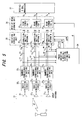
- Fig. 5 is a diagram illustrating the structure of a radio receiving apparatus according to a first embodiment of the present invention. Components identical with those of Figs. 1 and 4 are designated by like reference characters.
- the mobile station 11 wirelessly transmits a multicarrier signal of frequencies f 1 to f N .
- the radio waves (beams) of this radio signal impinge upon the linear array antenna (where the number of antennas is M) 31 of the base station 21 at an angle ⁇ .
- Antennas 31 1 to 31 M of the array antenna input the received signal to radio receiving circuits 32 1 to 32 M , respectively.
- the radio receiving circuits 32 1 to 32 M amplify the respective radio signals, subject the radio signals to frequency down-conversion processing and AD conversion processing and output baseband signals of the combined N-number of carriers.
- Narrow-band-signal extracting units 33 1 to 33 M respectively separate and output signal components r f1 (1) to r fN (1) ; r f1 (2) to r fN (2) ; ⁇ ; r f1 (M) to r fN (M) of N-number of frequencies f 1 to f N from the baseband signals that enter from the radio receiving circuits 32 1 to 32 M .
- the narrow-band-signal extracting units 33 1 to 33 M generate the subcarrier components by FFT processing.
- a phase-variation & arrival-direction estimating unit 34 obtains the beam arrival direction ⁇ and phase-shift difference ⁇ (2) in accordance with Equations (10) and (11) using baseband signals r f1 (1) , r fN (1) and baseband signals r f1 (2) r fN (2) of frequencies f 1 , f N of antennas 31 1 , 31 2 , respectively.
- phase-variation & arrival-direction estimating unit 34 obtains a phase-shift difference ⁇ (3) in accordance with Equation (11) using baseband signals r f1 (2) , r fN (2) and baseband signals r f1 (3) , r fN (3) of frequencies f 1 , f N of antennas 31 2 , 31 3 , respectively.
- the phase-variation & arrival-direction estimating unit 34 obtains a phase-shift difference ⁇ (M) in accordance with Equation (11) using baseband signals r f1 (M-1) , r fN (M-1) and baseband signals r f1 (M) , r fN (M) of frequencies f 1 , f N of antennas 31 M-1 , 31 M , respectively.
- ⁇ phase-shift difference
- the correction unit 35 2 imparts a phase characteristic - ⁇ (2) to the signal components r f1 (2) to r fN (2) of the N-number of frequencies f 1 to f N , thereby canceling the phase-shift amount ⁇ (2) in the radio receiving circuit 32 2 .
- the correction unit 35 M imparts a phase characteristic - ⁇ (M) to the signal components r f1 (M) to r fN (M) of the N-number of frequencies f 1 to f N , thereby canceling the phase-shift amount ⁇ (M) in the radio receiving circuit 32 M .
- a receive beam forming unit 36 has a beam former 36 1 for frequency f 1 that subjects M-number of signal components of frequency f 1 , which are output from the correction units 35 1 to 35 M , to prescribed weighting using the arrival direction ⁇ , and combines the signal components thus weighted.
- the beam former 36 1 forms a signal component S 1 of frequency f 1 so as to have a peak in the direction of mobile station 11.
- the receive beam forming unit 36 has a beam former 36 2 for frequency f 2 that subjects M-number of signal components of frequency f 2 , which are output from the correction units 35 1 to 35 M , to prescribed weighting using the arrival direction ⁇ , and combines the signal components thus weighted, thereby forming a signal component S 2 of frequency f 2 so as to have a peak in the direction of mobile station 11.
- a beam former 36 N for frequency f N subjects M-number of signal components of frequency f N , which are output from the correction units 35 1 to 35 M , to prescribed weighting using the arrival direction ⁇ , and combines the signal components thus weighted, thereby forming a signal component S N of frequency f N so as to have a peak in the direction of mobile station 11.
- a receive-signal processor 37 subjects the carrier signals S 1 to S N of frequencies f 1 to f N , respectively, to error detection and correction and to demodulation processing and outputs the result.
- the reason for estimating the beam arrival direction ⁇ and the phase-shift amounts ⁇ (2) to ⁇ (M) using the baseband signals of frequencies f 1 , f N in the phase-variation & arrival-direction estimating unit 34 is that estimation can be performed more precisely by using carriers whose frequencies are as far apart from each other as possible. That is, in order to obtain the phase-shift amount ⁇ that is proportional to frequency, as shown in Fig. 3, estimation is less susceptible to error if the frequencies are far apart rather than close together.
- correction for variation and estimation of arrival direction can be performed through a simple arrangement without additionally providing a reference-signal insertion circuit, a radio receiving circuit for calibration or a beacon station, etc., as required in the prior art.
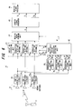
- Fig. 6 is a diagram illustrating the structure of a radio receiving apparatus according to a second embodiment of the present invention. Components identical with those of Figs. 1 and 4 are designated by like reference characters.
- the mobile station 11 wirelessly transmits a multicarrier signal of frequencies f 1 to f N .
- the radio waves (beams) of this radio signal impinge upon the linear array antenna (where the number of antennas is M) 31 of the base station 21 at an angle ⁇ .
- the antennas 31 1 to 31 M of the array antenna input the received signals to the radio receiving circuits 32 1 to 32 M , respectively.
- the radio receiving circuits 32 1 to 32 M amplify the radio signals, subject the radio signals to frequency down-conversion processing and AD conversion processing and output baseband signals of the combined N-number of carriers.
- Narrow-band-signal extracting units 41 1 to 41 M respectively separate and output the signal components r f1 (1) , r fN (1) ; r f1 (2) , r fN (2) ; ⁇ ; r f1 (M) , r fN (M) of two frequencies f 1 and f N from the baseband signals that enter from the radio receiving circuits 32 1 to 32 M .
- a phase-variation & arrival-direction estimating unit 42 obtains the beam arrival direction ⁇ and difference ⁇ (2) between the amounts of phase shift in accordance with Equations (10) and (11) using the baseband signals r f1 (1) , r fN (1) and the baseband signals r f1 (2) ' r fN (2) of frequencies f 1 and f N of antennas 31 1 , 31 2 , respectively.
- phase-variation & arrival-direction estimating unit 42 obtains the difference ⁇ (3) between the amounts of phase shift in accordance with Equation (11) using the baseband signals r f1 (2) , r fN (2) and the baseband signals r f1 (3) , r fN (3) of frequencies f 1 and f N of antennas 31 2 , 31 3 , respectively.
- the phase-variation & arrival-direction estimating unit 42 obtains the difference ⁇ (M) between the amounts of phase shift in accordance with Equation (11) using baseband signals r f1 (M-1) , r fN (M-1) and baseband signals r f1 (M) , r fN (M) of frequencies f 1 and f N of antennas 31 M-1' 31 M , respectively.
- ⁇ (M) the difference between the amounts of phase shift in accordance with Equation (11) using baseband signals r f1 (M-1) , r fN (M-1) and baseband signals r f1 (M) , r fN (M) of frequencies f 1 and f N of antennas 31 M-1' 31 M , respectively.
- the beam arrival direction ⁇ and phase-shift amounts ⁇ (2) to ⁇ (M) that prevail in the other radio receiving circuits 32 2 to 32 M when the amount ⁇ (1) of phase shift of radio receiving circuit 32 1 of the first antenna 31 1
- a correction unit 43 2 imparts a phase characteristic - ⁇ (2) to the baseband signal that is output from the radio receiving circuit 32 2 , thereby canceling the phase-shift amount ⁇ (2) in the radio receiving circuit 32 2 .
- a correction unit 43 M imparts a phase characteristic - ⁇ (M) to the baseband signal that is output from the radio receiving circuit 32 M , thereby canceling the phase-shift amount ⁇ (M) in the radio receiving circuit 32 M .
- a receive beam forming unit 44 subjects M-number of baseband signals that are output from each of the correction units 43 1 to 43 M to prescribed weighting using the arrival direction ⁇ and combines each of the signal components thus weighted. As a result, the receive beam forming unit 44 forms a baseband signal S so as to have a peak in the direction of the mobile station 11.
- a carrier signal generator 45 separates carrier signal components S 1 to S N of frequencies f 1 to f N from the baseband signal S and outputs these carrier signal components. In case of OFDM transmission, the carrier signal generator 45 is constituted by an FFT processor, and the subcarrier components can be generated by FFT processing.
- a receive-signal processor 46 subjects the carrier signals S 1 to S N of frequencies f 1 to f N to error detection and correction and to demodulation processing and outputs the result.
- correction (calibration) for variation and estimation of arrival direction can be performed through a simple arrangement without additionally providing a reference-signal insertion circuit, a radio receiving circuit for calibration or a beacon station, etc., as required in the prior art. Further, the arrangement can be simplified because it is unnecessary to provide a receive beam former for every carrier.
- the beam arrival direction ⁇ and the phase-shift amounts ⁇ 21 to ⁇ M1 are estimated using the baseband signals of frequencies f 1 and f N .
- the accuracy of estimation can be improved by estimating and averaging the beam arrival direction ⁇ and phase-shift amounts ⁇ (2) to ⁇ (M) using the baseband signals of other frequencies f i , f j .
- Fig. 7 is a diagram useful in describing a method of improving estimation accuracy in a system of four carriers and two antennas.
- Combinations of frequencies used in order to estimate the beam arrival direction ⁇ and phase-shift amount ⁇ (2) are six in number, namely (1) f 1 , f 2 , (2) f 1 , f 3 , (3) f 1 , f 4 , (5) f 2 , f 4 and (6) f 3 , f 4 . Accordingly, the accuracy of estimation can be improved by estimating and averaging the beam arrival direction ⁇ and phase-shift amount ⁇ (2) with regard to several combinations.
- Fig. 8 is a diagram useful in describing a method of improving estimation accuracy in a system of N carriers and M antennas. Here the accuracy of estimation can be improved by estimating and averaging the beam arrival direction ⁇ and phase-shift amounts ⁇ (2) to ⁇ (M) with regard to a plurality of combinations in a manner similar to the case of four carriers and two antennas.
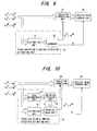
- Fig. 9 is a block diagram illustrating an embodiment of the phase-variation & arrival-direction estimating unit 34 in a method of finding a simple mean. Components identical with those of Fig. 5 are designated by like reference characters.
- the phase-variation & arrival-direction estimating unit 34 is constituted by an estimation unit 51 for estimating the beam arrival direction ⁇ and the phase-shift amounts ⁇ (2) to ⁇ (M) with regard to each combination of frequencies, and an averager 52 for obtaining the simple mean with regard to a plurality of beam arrival directions ⁇ and each of the phase-shift amounts ⁇ (2) to ⁇ (M) that have been obtained with regard to each combination of frequencies.
- Finding the simple mean is a method of dividing the sum total of all samples by the number of samples and adopting the resulting value as the average value.
- Fig. 10 is a block diagram illustrating an embodiment of the phase-variation & arrival-direction estimating unit 34, which calculates an average upon applying weighting that conforms to reception level. Components identical with those of Fig. 5 are designated by like reference characters.
- the phase-variation & arrival-direction estimating unit 34 is constituted by the estimation unit 51 for estimating the beam arrival direction ⁇ and the phase-shift amounts ⁇ (2) to ⁇ (M) with regard to each combination of frequencies; a level measurement unit 53 for measuring the levels of the carrier signal components r f1 (1) to r fN (1) ; r f1 (2) to r fN (2) ; ⁇ ; r f1 (M) to r fN (M) of respective ones of the antennas; a weighting decision unit 54 for deciding weighting coefficients based upon levels of the carrier signal components with regard to each combination; and a weighted-mean unit 55 for multiplying the beam arrival direction ⁇ and each of the phase-shift amounts ⁇ (2) to ⁇ (M) , which have been obtained with regard to each combination, by the weighting coefficients, and calculating the averages.
- the weighted-mean unit 55 obtains the phase-shift amount of each antenna by performing weighting and averaging in such a manner that maximum-ratio combining is performed between carriers based upon the level of each carrier signal of each antenna obtained by the level measurement unit 53.
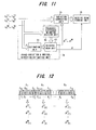
- Fig. 11 is a block diagram illustrating an embodiment of the phase-variation & arrival-direction estimating unit 34, which calculates an average upon applying weighting that conforms to the frequency spacing of a combination.
- Components identical with those of Fig. 5 are designated by like reference characters.
- the phase-variation & arrival-direction estimating unit 34 is constituted by the estimation unit 51 for estimating the beam arrival direction ⁇ and the phase-shift amounts ⁇ (2) to ⁇ (M) with regard to each combination of frequencies; a frequency-difference weighting decision unit 56 for deciding weighting coefficients that conform to frequency spacing with regard to each combination of frequencies; and a weighted-mean unit 57 for multiplying the beam arrival direction ⁇ and each of the phase-shift amounts ⁇ (2) to ⁇ (M) , which have been obtained with regard to each combination of frequencies, by the weighting coefficients, and calculating the averages.
- Fig. 12 is a diagram useful in describing the principles of a third embodiment of the present invention.
- OFDM subcarriers f 1 to f N are partitioned into F-number of bands B 1 to B F .
- the number N of subcarriers is 128, 256, 512, etc.
- the phase-variation & arrival-direction estimating unit 34 obtains phase-shift amounts ⁇ (1) [1] to ⁇ (M) [1]; ⁇ (1) [2] to ⁇ (M) [2]; ⁇ ; ⁇ (1) [F] to ⁇ (M) [F] in respective ones of the bands B 1 to B F using both end frequencies f 1 , f i ; f i+1 , f j ; ⁇ ; f k , f N of respective ones of the bands B 1 to B F , and corrects for the phase-shift amount on a per-frequency-band basis.
- Fig. 13 is a diagram illustrating the structure of a radio receiving apparatus according to the third embodiment. Components identical with those of Fig. 5 are designated by like reference characters.
- the apparatus according to this embodiment differs in that (1) the phase-variation & arrival-direction estimating unit 34 obtains the phase-shift amounts ⁇ (1) [1] to ⁇ (M) [1]; ⁇ (1) [2] to ⁇ (M) [2]; ...; ⁇ (1) [F] to ⁇ (M) [F] in respective ones of the bands B 1 to B F with regard to respective ones of the radio receiving circuits 32 1 to 32 M , and inputs these phase-shift amounts to the variation correcting unit 35, and (2) the correction units 35 1 to 35 M corresponding to the radio receiving circuits 32 1 to 32 M correct for the phase-shift amounts for each of the bands B 1 to B F obtained by partitioning.
- Fig. 14 illustrates an example of the structure of the correction unit 35 2 corresponding to one radio receiving circuit 32 2 .
- the correction unit 35 2 has correctors 61 1 to 61 F for bands B 1 to B F , respectively.
- the corrector 61 1 for band B 1 imparts a phase characteristic - ⁇ (2) [1] to the signal components r f1 (2) to r fi (2) of the frequencies f 1 to f i , thereby canceling the phase-shift amount ⁇ (2) [1] of band B1 in the radio receiving circuit 32 2 .
- the corrector 61 2 for band B 2 imparts a phase characteristic - ⁇ (2) [2] to the signal components r fi+1 (2) to r fj (2) of the frequencies f i+1 to f j , thereby canceling the phase-shift amount ⁇ (2) [2] of band B 2 in the radio receiving circuit 32 2 .
- the corrector 61 F for band B F imparts a phase characteristic - ⁇ (2) [F] to the signal components r fk (2) to r fN (2) of the frequencies f k to f N , thereby canceling the phase-shift amount ⁇ (2) [F] of band B F in the radio receiving circuit 32 2 .
- the embodiment described above relates to a case where the present invention is applied to a multicarrier communication scheme (inclusive of OFDM).
- a multicarrier communication scheme inclusive of OFDM
- the invention is applicable not only to a multicarrier scheme but also to a single-carrier scheme.
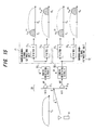
- Fig. 15 is a diagram useful in describing principles in a case where the present invention is applied to a wide-band single-carrier signal. Components identical with those of Fig. 1 are designated by like reference characters.
- This embodiment differs in that the mobile station 11 transmits a wide-band single-carrier signal of center frequency f c ; two filters 71 1 , 71 2 that construct a narrow-band-signal extracting unit 71 extract and output signal components r f1 (1) , r f4 (1) of frequencies f 1 , f 4 , respectively, from the output signal of the radio receiving circuit 32 1 ; and two filters 72 1 , 72 2 that construct a narrow-band signal extracting unit 72 extract and output signal components r f1 (2) , r f4 (2) of frequencies f 1 , f 4 , respectively, from the output signal of the radio receiving circuit 32 2 .
- Fig. 16 illustrates an embodiment of a case where the present invention is applied to single-carrier signal. Components identical with those of Figs. 1 and 4 are designated by like reference characters.
- This embodiment differs in that (1) narrow-band-signal extracting units 71 to 7M are each constituted by two filters (see Fig. 15) that extract and output signal components r f1 (1) , r fN (1) to r f1 (M) , r fN (M) of frequencies f 1 , f N from the output signals of the radio receiving circuits 32 1 to 32 M ; and (2) and the phase-variation & arrival-direction estimating unit 42 estimates the beam arrival direction ⁇ and phase-shift amounts ⁇ (1) to ⁇ (M) using these signal components.
- the present invention provides a multicarrier communication scheme (inclusive of OFDM), which is viewed as promising in future wireless communications, with a wireless communication apparatus whereby a variation that occurs in the radio receiving circuit of each of a number of antennas can be corrected for and arrival direction estimated through a simple arrangement without adding on a reference-signal insertion circuit or a radio receiving circuit. Further, the fact that the apparatus is simplified in structure is advantageous in that cost can be reduced, reliability enhanced and maintenance management simplified.
Landscapes
- Engineering & Computer Science (AREA)
- Computer Networks & Wireless Communication (AREA)
- Signal Processing (AREA)
- Variable-Direction Aerials And Aerial Arrays (AREA)
- Radio Transmission System (AREA)
Abstract
Disclosed is a wireless communication apparatus having an array antenna constituted by a plurality of antennas (311 to 31M, radio receiving circuits (321 to 32M, which are provided for respective ones of the antennas, for amplifying respective ones of antenna receive signals and applying a frequency conversion to the baseband signals, and a demodulator for demodulating receive data from the baseband signals. A narrow-band-signal extracting unit (331 to 33M) extracts two narrow-band signals, which have the maximum frequency spacing between them, from the baseband signals of each of the antennas, an estimating unit (34) estimates phase variation in each radio receiving circuit using the two narrow-band signals of each antenna, and a phase-variation correcting unit (35) corrects for phase variation in each radio receiving circuit. The estimating unit estimates the direction of signal arrival using narrow-band signals of at least two antennas, a beam former (36) applies receive beam-forming processing to each corrected signal based upon the direction of signal arrival, and a receive-signal processor (37) demodulates receive data from the receive signal that has undergone beam-forming processing.
Description
- This invention relates to a wireless communication apparatus and to a method of correcting for phase variation. More particularly, the invention relates to a wireless communication apparatus having an array antenna constituted by a plurality of antennas, a radio receiving circuit, which is provided for every antenna, for amplifying each antenna receive signal and subjecting baseband signals thereof to a frequency conversion, and a demodulator for demodulating receive data from the baseband signals, and to a method of correcting for phase variation in this apparatus.
- A CDMA scheme in a digital cellular wireless communication system using DS-CDMA techniques assigns channels by code so that communication may be performed simultaneously on these channels. However, signals from other communicating channels interfere and, as a result, there is a limit on the number of channels that can communicate simultaneously, i.e., there is a limit on channel capacity. The adaptive array antenna (AAA) is now the focus of attention as it is an effective means of suppressing interference in order to increase channel capacity.
- An adaptive array antenna forms a beam directed toward a desired user adaptively in accordance with the environment but nulls the beam with respect to a user who is a major source of interference, thereby making it possible to increase channel capacity. That is, an adaptive array antenna forms a beam in the direction of a desired user and nulls the beam in the direction of user who is a source of much interference, thereby making it possible to receive radio waves from a desired user with a high degree of sensitivity while radio waves from a major interference source are not received. This enables the amount of interference to be reduced and, as a result, enables an increase in channel capacity.
- Fig. 17 is a block diagram of a radio receiving apparatus that employs an adaptive array antenna. The adaptive array antenna AAA has
antennas A# 1 to A#n that receive signals and input these signals toradio circuits 11 to 1n, respectively. Theradio circuits 11 to 1n amplify the receive radio signals and downconvert these radio signals to baseband signals.AD converters 21 to 2n convert the baseband signals to digital data and input the digital data to abaseband processor 3. The latter executes signal processing for every antenna element and outputs complex receive data in digital form. An arrival-direction estimatingunit 4 estimates the arrival direction θ of a signal using the complex digital receive data of every antenna element. A beam forming device (receive beam former) 5 forms a beam having a peak in the direction of the signal source using the estimated value θ in the signal arrival direction that enters from the arrival-direction estimatingunit 4. That is, the receive beam former 5 extracts the desired signal and sends it to a receive-signal processor 6 while suppressing interference and noise. The receive-signal processor 6 modulates and outputs the receive data upon executing receive processing by a well-known method. Various implementations are available for the receive beam former 5, which directs the beam toward the signal source utilizing arrival-direction information. For example, it is possible to receive a beam oriented in a desired signal-arrival direction by exploiting a beam forming method described in O.L. Frost, "An algorithm for linearly constrained adaptive array processing," Proc. IEEE, vol. 60, no. 8, pp. 926 - 935 (1975), and J. Xin, H. Tsuji, Y. Hase, and A. Sano, "Array beamforming based on cyclic signal detection," Proc. IEEE 48th Vehicular Technology Conference, pp. 890 - 984, Ottawa, Canada (1998). - A radio apparatus using an adaptive array antenna employs radio circuits that differ for every antenna, as described in conjunction with Fig. 17. If the radio circuits have the same amplitude and phase characteristics as one another, no problems arise. Usually, however, these characteristics differ. Owing to this variation in characteristics, each antenna receive signal is imparted with a different amplitude and phase-shift characteristic by the receive circuit. Even if the beam-arrival direction (the direction of the mobile station) is estimated using these signals imparted with different amplitude and phase characteristics, estimation cannot be performed accurately. For this reason, a variety of variation correction techniques referred to as antenna calibration have been proposed.
- A first example of this prior art is a method of mixing a reference signal with the receive signal of each antenna (see the specification of
Japanese Patent Application Laid-Open No. 2001-156688 - A second example of this prior art is a method of using a radio receiving circuit for calibration (see papers of the Institute of Electronics, Information and Communication Engineers, RCS2001-261). According to this example of the prior art, a radio receiving unit is provided with a radio receiving circuit B for calibration in addition to a radio receiving circuit A of each antenna, and the receive signal of the radio receiving circuit A is corrected based upon the characteristic of the radio receiving circuit A of each antenna relative to the radio receiving circuit B for calibration.
- A third example of this prior art is a method of deploying in space a beacon station (a radio signal transmitting station for calibration) whose arrival direction is known, measuring a characteristic error of a radio receiving circuit using the signal of the beacon and correcting a communication receive signal based upon the characteristic error.
- With the first and second examples of the prior art mentioned above, it is necessary to add on a circuit for injecting the reference signal or the radio receiving circuit for calibration. The third example of the prior art requires the deployment of the beacon station. These items of hardware complicate the system and are not necessarily the best in terms of cost.
- Accordingly, an object of the present invention is to so arrange it that phase variation in each radio receiving circuit and signal arrival direction can be estimated without adding on a reference-signal insertion circuit, a radio receiving circuit for calibration or a beacon station, etc.
- Another object of the present invention is to correct phase variation in each radio receiving circuit based upon an estimated phase variation and improve reception accuracy by carrying out beam forming oriented in the direction of signal arrival.
- A further object of the present invention is to implement correction of variation and estimation of arrival direction through a simple arrangement in multicarrier modulation schemes (inclusive of OFDM) viewed as promising in future wireless communications.
- The present invention provides a wireless communication apparatus having an array antenna constituted by a plurality of antennas, radio receiving circuits, which are provided for respective ones of the antennas, for amplifying respective ones of antenna receive signals and frequency converting the antenna receiving signals to baseband signals, and a demodulator for demodulating receive data from the baseband signals, as well as to a method of correcting for phase variation in this apparatus.
- The wireless communication apparatus according to the present invention comprises a narrow-band-signal extracting unit for extracting narrow-band signals from the baseband signals of each antenna; an estimating unit for estimating phase variation in each radio receiving circuit using the narrow-band signals of each antenna; a correcting unit for correcting for phase variation in each radio receiving circuit and outputting a corrected signal; and a receive-signal processor for demodulating receive data from the corrected signal.
- The wireless communication apparatus further comprises an estimating unit for estimating direction of signal arrival using narrow-band signals of at least two antennas; and a beam former for applying receive beam-forming processing to each corrected signal based upon the direction of signal arrival; wherein the receive-signal processor demodulates receive data from the receive signal that has undergone beam-forming processing.
- If the system is a multicarrier communication system, the estimating unit uses each carrier signal of the multicarrier or each subcarrier signal of OFDM as the narrow-band signal of each antenna. If the system is wide-band single-carrier system, then the estimating unit uses a narrow-band signal, which has been extracted using filters, as the narrow-band signal of each antenna.
- In order to improve the accuracy of estimation, the estimating unit uses narrow-band signals of two carriers of maximum frequency spacing as the narrow-band signals of each of the antennas.
- Further, in order to improve the accuracy of estimation, the estimating unit obtains phase variations with regard to a plurality of sets of carriers, weights the phase variation of each set based upon the reception signal levels of the carriers, and concludes that the weighted mean value is the true phase variation.
- Further, in order to improve the accuracy of estimation, the estimating unit obtains phase variations with regard to a plurality of sets of carriers, weights the phase variation of each set based upon frequency spacing of the carriers, and concludes that the weighted mean value is the true phase variation.
- Further, in a case where the radio receiving circuits have a frequency characteristics in wide-band transmission, the estimating unit partitions subcarriers into a plurality of frequency regions the frequency characteristics whereof are regarded as being substantially uniform, and corrects for the phase variation of the radio receiving circuits and estimates the arrival direction for every region into which the subcarriers have been partitioned.
- A method of correcting for phase variation in the radio receiving circuit according to the present invention comprises: a step of extracting narrow-band signals from the baseband signals of each antenna; a step of estimating phase variation in each radio receiving circuit using the narrow-band signals of each antenna; and a step of correcting for phase variation in each radio receiving circuit by subjecting an output signal of each radio receiving circuit to a phase correction having a phase opposite that of the phase variation.
- The method further comprises the steps of estimating direction of signal arrival using narrow-band signals of at least two antennas; applying receive beam-forming processing to each corrected signal based upon the direction of signal arrival; and demodulating receive data from the receive signal that has undergone beam-forming processing.
- In accordance with the present invention, narrow-band signals are extracted from baseband signals antenna by antenna, the phase variation of each radio receiving circuit is estimated using the narrow-band signals of each antenna, and phase is corrected for so as to invert the phase of the phase variation, thereby correcting for phase variation in each radio receiving circuit. As a result, it is unnecessary to add on special circuits for estimating phase variation, as is required in the prior art, and therefore phase variation in each radio receiving circuit can be estimated and corrected for through a simple arrangement.
- Further, in accordance with the present invention, direction of signal arrival is estimated using narrow-band signals of at least two antennas, receive beam-forming processing is applied to each phase-variation-corrected signal based upon the direction of signal arrival, and receive data is demodulated from each receive signal that has undergone beam-forming processing. This makes it possible to improve reception accuracy.
- Further, the present invention is such that each carrier signal of a multicarrier or each subcarrier signal of OFDM is used as the narrow-band signal of each antenna if the system is a multicarrier communication system. If the system is a wide-band single-carrier system, a narrow-band signal that has been extracted using a filter can be used. As a result, regardless of whether the system is for multicarrier communication or wide-band single-carrier transmission, phase variation of each radio receiving circuit and direction of signal arrival can be estimated and reception accuracy can be improved by correcting for variation and executing beam-forming processing.
- Further, in accordance with the present invention, the accuracy of phase-variation estimation can be improved as well as the accuracy of reception by (1) using narrow-band signals of two carriers of maximum frequency spacing as the narrow-band signals of each of the antennas, or (2) obtaining phase variations with regard to a plurality of sets of carriers, weighting the phase variation of each set based upon the reception signal levels of the carriers, and adopting a weighted mean value as true phase variation, or (3) obtaining phase variations with regard to a plurality of sets of carriers, weighting the phase variation of each set based upon frequency spacing of the carriers, and concluding that the weighted mean value is the true phase variation.
- Further, in accordance with the present invention, in a case where radio receiving circuits have frequency characteristics in wide-band transmission, the estimating unit partitions subcarriers into a plurality of frequency regions the frequency characteristics whereof are regarded as being substantially uniform, and corrects for the phase variation of the radio receiving circuit and estimates the arrival direction for every region into which subcarriers have been divided. As a result, the accuracy of phase-variation estimation can be improved as well as the accuracy of reception
- Other features and advantages of the present invention will be apparent from the following description taken in conjunction with the accompanying drawings.
-
- Fig. 1 is a diagram useful in describing the principles of variation correction and estimation of arrival direction according to the present invention;
- Fig. 2 is a diagram useful in describing delay caused by placement of an array antenna;
- Fig. 3 is a diagram illustrating the relationship between frequency of a receive signal and amount of phase shift;
- Fig. 4 is a diagram useful in describing the principles of variation correction and estimation of arrival direction in a general case where the number of antennas is M and the number of carriers is N;
- Fig. 5 is a diagram illustrating the structure of a radio receiving apparatus according to a first embodiment of the present invention;
- Fig. 6 is a diagram illustrating the structure of a radio receiving apparatus according to a second embodiment of the present invention;
- Fig. 7 is a diagram useful in describing a method of improving estimation accuracy in a system of four carriers and two antennas;
- Fig. 8 is a diagram useful in describing a method of improving estimation accuracy in a system of N carriers and M antennas;
- Fig. 9 is a block diagram illustrating an embodiment of a unit for estimating phase variation and arrival direction in a method of finding a simple mean;
- Fig. 10 is a block diagram illustrating an embodiment of the unit for estimating phase variation and arrival direction, the unit performing weighting that conforms to reception level and then averaging;
- Fig. 11 is a block diagram illustrating an embodiment of a unit for estimating phase variation and arrival direction, the unit performing weighting that conforms to the frequency spacing of a combination and then averaging;
- Fig. 12 is a diagram useful in describing the principles of a third embodiment of the present invention;
- Fig. 13 is a diagram illustrating the structure of a radio receiving apparatus according to the third embodiment;
- Fig. 14 illustrates an example of the structure of a correcting unit corresponding to a radio receiving circuit;
- Fig. 15 is a diagram useful in describing principles in a case where the present invention is applied to a single-carrier signal;
- Fig. 16 illustrates an embodiment in which the present invention is applied to single-carrier signal; and
- Fig. 17 is a diagram illustrating the structure of a radio receiving apparatus that employs an adaptive array antenna.
- Fig. 1 is a diagram useful in describing the principles of variation correction and estimation of arrival direction according to the present invention. This is for a case where the number of carriers is four and the number of antennas is two.
Reference numerals mobile station 11 impinges upon the linear array antenna (where the number of antennas is two) 31 of thebase station 21 at an angle θ.Antennas - Let ξf1, ξf2, ξf3, ξf4 represent the propagation-path fading characteristics with respect to the frequencies f1, f2, f3, f4, let rf1 (1), rf2 (1), rf3 (1), rf4 (1) represent the baseband signals of the frequencies f1, f2, f3, f4 that are output from the radio receiving circuit 321, let rf1 (2), rf2 (2), rf3 (2), rf4 (2) represent the baseband signals of the frequencies f1, f2, f3, f4 that are output from the radio receiving circuit 322, and let the amplitude and phase characteristics of the radio receiving circuits 321, 322 be expressed respectively as follows:
- a(1), a(2)
-


where c represents the velocity of light. Equation (1) indicates that the baseband signal is influenced by fading ξf1, that a phase delay of
is produced by the placement of the array antenna, and that the radio receiving circuit 321 exhibits the amplitude and phase characteristic
a(1)
The same can be considered to hold true for Equations (2) to (4). Fig. 2 is a diagram useful in describing delay ascribable to the placement of the antenna array. If we let d represent the distance between antennas and θ the beam incidence angle, the difference between the distance from themobile station 11 to midpoint O between the antennas and the distance from themobile station 11 to theantennas
If the center frequency of the multicarrier is fc, the wavelength thereof is λc, Equation (3) is divided by Equation (1), Equation (4) is divided by Equation (2) and the relation λc = c·fc is applied, the equations indicated below are obtained. - Specifically, from (3)/(1), we obtain the following:

and from (4)/(2), we obtain the following:
sinθ and (a(2)/a(1))
are unknown but everything else is known. If we let the phase terms on the right side of Equations (5) and (6) be represented respectively by the following:
let the ratio (a(2)/a(1)) on the right side of Equations (5) and (6) be represented by
and we compare the phase terms, then the equations set forth below are obtained. It should be noted that φ21 represents the difference (the phase variation) between the amounts of phase shift of the radio receiving circuits 321, 322, and that this is the amount of phase shift of the radio receiving circuit 322 when the amount of phase shift of the radio receiving circuit 321 is adopted as the reference.

Subtracting Equation (7) from Equation (8) gives us the following equation:
and the beam arrival direction θ is given by the following equation:
Furthermore, if we eliminate sinθ from Equations (7) and (8), we obtain the following equation:
and the phase for calibration (for correcting for phase variation) can be obtained. - Fig. 3 is a diagram illustrating the relationship between frequency f of a receive signal and amount Φ of phase shift. Here Φf1 is the difference between amounts of phase shift in the radio receiving circuits 321, 322 at frequency f1, Φf2 is the difference between amounts of phase shift in the radio receiving circuits 321, 322 at frequency f2, and φ21 is the difference between amounts of phase shift in the radio receiving circuits 321, 322 at frequency fc.
The foregoing is for a case where the number of carriers is four and the number of antennas is two. However, the invention is also applicable to a general case where the number of antennas is M and the number of carriers is N, as shown in Fig. 4. Specifically, in a manner similar to the case for two antennas with respect toantennas antennas 2 between phase shifts is obtained using baseband signals rf1 (2), rfN (2) and baseband signals rf1 (3), rfN (3). Similarly, with regard toantennas first antenna 311 is assumed to be zero. It should be noted that φ31 = φ32 + φ21, ···, φM1 = φM,M-1 + ··· + φ32 + φ21. - Fig. 5 is a diagram illustrating the structure of a radio receiving apparatus according to a first embodiment of the present invention. Components identical with those of Figs. 1 and 4 are designated by like reference characters.
- The
mobile station 11 wirelessly transmits a multicarrier signal of frequencies f1 to fN. The radio waves (beams) of this radio signal impinge upon the linear array antenna (where the number of antennas is M) 31 of thebase station 21 at an angle θ.Antennas 311 to 31M of the array antenna input the received signal to radio receiving circuits 321 to 32M, respectively. The radio receiving circuits 321 to 32M amplify the respective radio signals, subject the radio signals to frequency down-conversion processing and AD conversion processing and output baseband signals of the combined N-number of carriers. Narrow-band-signal extracting units 331 to 33M respectively separate and output signal components rf1 (1) to rfN (1); rf1 (2) to rfN (2); ···; rf1 (M) to rfN (M) of N-number of frequencies f1 to fN from the baseband signals that enter from the radio receiving circuits 321 to 32M. In case of OFDM communication in which data is transmitted on a multiplicity of subcarriers (e.g., 256 subcarriers), the narrow-band-signal extracting units 331 to 33M generate the subcarrier components by FFT processing. - A phase-variation & arrival-
direction estimating unit 34 obtains the beam arrival direction θ and phase-shift difference φ(2) in accordance with Equations (10) and (11) using baseband signals rf1 (1), rfN (1) and baseband signals rf1 (2) rfN (2) of frequencies f1, fN ofantennas direction estimating unit 34 obtains a phase-shift difference φ(3) in accordance with Equation (11) using baseband signals rf1 (2), rfN (2) and baseband signals rf1 (3), rfN (3) of frequencies f1, fN ofantennas direction estimating unit 34 obtains a phase-shift difference φ(M) in accordance with Equation (11) using baseband signals rf1 (M-1), rfN (M-1) and baseband signals rf1 (M), rfN (M) of frequencies f1, fN ofantennas first antenna 311 is assumed to be zero. - The
variation correcting unit 35 hascorrection units 351 to 35M for imparting phase characteristics -φ(1) to -φ(M), the signs whereof are opposite those of the phase-shift amounts φ(1) to φ(M) in the radio receiving circuits 321 to 32M, respectively, to respective ones of the input signals, thereby nulling the total phase-shift amounts. That is, thecorrection unit 351 imparts a phase characteristic -φ(1) = 0 to the signal components rf1 (1) to rfN (1) of the N-number of frequencies f1 to fN, thereby canceling the phase-shift amount φ(1) in the radio receiving circuit 321. Further, thecorrection unit 352 imparts a phase characteristic -φ(2) to the signal components rf1 (2) to rfN (2) of the N-number of frequencies f1 to fN, thereby canceling the phase-shift amount φ(2) in the radio receiving circuit 322. Similarly, thecorrection unit 35M imparts a phase characteristic -φ(M) to the signal components rf1 (M) to rfN (M) of the N-number of frequencies f1 to fN, thereby canceling the phase-shift amount φ(M) in the radio receiving circuit 32M. - A receive
beam forming unit 36 has a beam former 361 for frequency f1 that subjects M-number of signal components of frequency f1, which are output from thecorrection units 351 to 35M, to prescribed weighting using the arrival direction θ, and combines the signal components thus weighted. As a result, the beam former 361 forms a signal component S1 of frequency f1 so as to have a peak in the direction ofmobile station 11. Further, the receivebeam forming unit 36 has a beam former 362 for frequency f2 that subjects M-number of signal components of frequency f2, which are output from thecorrection units 351 to 35M, to prescribed weighting using the arrival direction θ, and combines the signal components thus weighted, thereby forming a signal component S2 of frequency f2 so as to have a peak in the direction ofmobile station 11. Similarly, a beam former 36N for frequency fN subjects M-number of signal components of frequency fN, which are output from thecorrection units 351 to 35M, to prescribed weighting using the arrival direction θ, and combines the signal components thus weighted, thereby forming a signal component SN of frequency fN so as to have a peak in the direction ofmobile station 11. - A receive-
signal processor 37 subjects the carrier signals S1 to SN of frequencies f1 to fN, respectively, to error detection and correction and to demodulation processing and outputs the result. - The reason for estimating the beam arrival direction θ and the phase-shift amounts φ(2) to φ(M) using the baseband signals of frequencies f1, fN in the phase-variation & arrival-
direction estimating unit 34 is that estimation can be performed more precisely by using carriers whose frequencies are as far apart from each other as possible. That is, in order to obtain the phase-shift amount Φ that is proportional to frequency, as shown in Fig. 3, estimation is less susceptible to error if the frequencies are far apart rather than close together. - Thus, in accordance with the first embodiment, correction (calibration) for variation and estimation of arrival direction can be performed through a simple arrangement without additionally providing a reference-signal insertion circuit, a radio receiving circuit for calibration or a beacon station, etc., as required in the prior art.
- Fig. 6 is a diagram illustrating the structure of a radio receiving apparatus according to a second embodiment of the present invention. Components identical with those of Figs. 1 and 4 are designated by like reference characters.
- The
mobile station 11 wirelessly transmits a multicarrier signal of frequencies f1 to fN. The radio waves (beams) of this radio signal impinge upon the linear array antenna (where the number of antennas is M) 31 of thebase station 21 at an angle θ. Theantennas 311 to 31M of the array antenna input the received signals to the radio receiving circuits 321 to 32M, respectively. The radio receiving circuits 321 to 32M amplify the radio signals, subject the radio signals to frequency down-conversion processing and AD conversion processing and output baseband signals of the combined N-number of carriers. Narrow-band-signal extracting units 411 to 41M respectively separate and output the signal components rf1 (1), rfN (1); rf1 (2), rfN (2); ···; rf1 (M), rfN (M) of two frequencies f1 and fN from the baseband signals that enter from the radio receiving circuits 321 to 32M. - A phase-variation & arrival-
direction estimating unit 42 obtains the beam arrival direction θ and difference φ(2) between the amounts of phase shift in accordance with Equations (10) and (11) using the baseband signals rf1 (1), rfN (1) and the baseband signals rf1 (2)' rfN (2) of frequencies f1 and fN ofantennas direction estimating unit 42 obtains the difference φ(3) between the amounts of phase shift in accordance with Equation (11) using the baseband signals rf1 (2), rfN (2) and the baseband signals rf1 (3), rfN (3) of frequencies f1 and fN ofantennas direction estimating unit 42 obtains the difference φ(M) between the amounts of phase shift in accordance with Equation (11) using baseband signals rf1 (M-1), rfN (M-1) and baseband signals rf1 (M), rfN (M) of frequencies f1 and fN ofantennas 31M-1' 31M, respectively. Thus are obtained the beam arrival direction θ and phase-shift amounts φ(2) to φ(M) that prevail in the other radio receiving circuits 322 to 32M when the amount φ(1) of phase shift of radio receiving circuit 321 of thefirst antenna 311 is assumed to be zero. - A
variation correcting unit 43 hascorrection units 431 to 43M for imparting phase characteristics -φ(1) to -φ(M), the signs whereof are opposite those of the phase-shift amounts φ(1) to φ(M) in the radio receiving circuits 321 to 32M, to respective ones of the input signals, thereby nulling the total phase-shift amounts. That is, thecorrection unit 431 imparts a phase characteristic -φ(1) = 0 to the baseband signal that is output from the radio receiving circuit 321, thereby canceling the phase-shift amount φ(1) in the radio receiving circuit 321. Further, acorrection unit 432 imparts a phase characteristic -φ(2) to the baseband signal that is output from the radio receiving circuit 322, thereby canceling the phase-shift amount φ(2) in the radio receiving circuit 322. Similarly, acorrection unit 43M imparts a phase characteristic -φ(M) to the baseband signal that is output from the radio receiving circuit 32M, thereby canceling the phase-shift amount φ(M) in the radio receiving circuit 32M. - A receive
beam forming unit 44 subjects M-number of baseband signals that are output from each of thecorrection units 431 to 43M to prescribed weighting using the arrival direction θ and combines each of the signal components thus weighted. As a result, the receivebeam forming unit 44 forms a baseband signal S so as to have a peak in the direction of themobile station 11. Acarrier signal generator 45 separates carrier signal components S1 to SN of frequencies f1 to fN from the baseband signal S and outputs these carrier signal components. In case of OFDM transmission, thecarrier signal generator 45 is constituted by an FFT processor, and the subcarrier components can be generated by FFT processing. - A receive-
signal processor 46 subjects the carrier signals S1 to SN of frequencies f1 to fN to error detection and correction and to demodulation processing and outputs the result. - Thus, in accordance with the second embodiment, correction (calibration) for variation and estimation of arrival direction can be performed through a simple arrangement without additionally providing a reference-signal insertion circuit, a radio receiving circuit for calibration or a beacon station, etc., as required in the prior art. Further, the arrangement can be simplified because it is unnecessary to provide a receive beam former for every carrier.
- In the first and second embodiments, the beam arrival direction θ and the phase-shift amounts φ21 to φM1 are estimated using the baseband signals of frequencies f1 and fN. However, the accuracy of estimation can be improved by estimating and averaging the beam arrival direction θ and phase-shift amounts φ(2) to φ(M) using the baseband signals of other frequencies fi, fj. Fig. 7 is a diagram useful in describing a method of improving estimation accuracy in a system of four carriers and two antennas. Combinations of frequencies used in order to estimate the beam arrival direction θ and phase-shift amount φ(2) are six in number, namely (1) f1, f2, (2) f1, f3, (3) f1, f4, (5) f2, f4 and (6) f3, f4. Accordingly, the accuracy of estimation can be improved by estimating and averaging the beam arrival direction θ and phase-shift amount φ(2) with regard to several combinations. Fig. 8 is a diagram useful in describing a method of improving estimation accuracy in a system of N carriers and M antennas. Here the accuracy of estimation can be improved by estimating and averaging the beam arrival direction θ and phase-shift amounts φ(2) to φ(M) with regard to a plurality of combinations in a manner similar to the case of four carriers and two antennas.
- Conceivable methods of averaging are as follows:
- (a) a method of finding the simple mean of each carrier;
- (b) a method of applying weighting conforming to the reliability (reception level) of each carrier and calculating the average;
- (c) a method of applying large weighting to frequencies that are far apart, by reason of the fact that such frequencies are less susceptible to noise, and averaging the results; and
- (d) a method that combines a plurality of the methods mentioned above.
- Fig. 9 is a block diagram illustrating an embodiment of the phase-variation & arrival-
direction estimating unit 34 in a method of finding a simple mean. Components identical with those of Fig. 5 are designated by like reference characters. The phase-variation & arrival-direction estimating unit 34 is constituted by anestimation unit 51 for estimating the beam arrival direction θ and the phase-shift amounts φ(2) to φ(M) with regard to each combination of frequencies, and anaverager 52 for obtaining the simple mean with regard to a plurality of beam arrival directions θ and each of the phase-shift amounts φ(2) to φ(M) that have been obtained with regard to each combination of frequencies. Finding the simple mean is a method of dividing the sum total of all samples by the number of samples and adopting the resulting value as the average value. - Fig. 10 is a block diagram illustrating an embodiment of the phase-variation & arrival-
direction estimating unit 34, which calculates an average upon applying weighting that conforms to reception level. Components identical with those of Fig. 5 are designated by like reference characters. The phase-variation & arrival-direction estimating unit 34 is constituted by theestimation unit 51 for estimating the beam arrival direction θ and the phase-shift amounts φ(2) to φ(M) with regard to each combination of frequencies; alevel measurement unit 53 for measuring the levels of the carrier signal components rf1 (1) to rfN (1); rf1 (2) to rfN (2); ···; rf1 (M) to rfN (M) of respective ones of the antennas; aweighting decision unit 54 for deciding weighting coefficients based upon levels of the carrier signal components with regard to each combination; and a weighted-mean unit 55 for multiplying the beam arrival direction θ and each of the phase-shift amounts φ(2) to φ(M), which have been obtained with regard to each combination, by the weighting coefficients, and calculating the averages. By way of example, the weighted-mean unit 55 obtains the phase-shift amount of each antenna by performing weighting and averaging in such a manner that maximum-ratio combining is performed between carriers based upon the level of each carrier signal of each antenna obtained by thelevel measurement unit 53. - Fig. 11 is a block diagram illustrating an embodiment of the phase-variation & arrival-
direction estimating unit 34, which calculates an average upon applying weighting that conforms to the frequency spacing of a combination. Components identical with those of Fig. 5 are designated by like reference characters. The phase-variation & arrival-direction estimating unit 34 is constituted by theestimation unit 51 for estimating the beam arrival direction θ and the phase-shift amounts φ(2) to φ(M) with regard to each combination of frequencies; a frequency-differenceweighting decision unit 56 for deciding weighting coefficients that conform to frequency spacing with regard to each combination of frequencies; and a weighted-mean unit 57 for multiplying the beam arrival direction θ and each of the phase-shift amounts φ(2) to φ(M), which have been obtained with regard to each combination of frequencies, by the weighting coefficients, and calculating the averages. - The foregoing embodiments relate to a case where a correction is applied upon estimating one of the phase-shift amounts φ(1) to φ(M) per each of the radio receiving circuits 321 to 32M. However, there are instances where in wide-band transmission such as OFDM transmission, the radio receiving circuits 321 to 32M have frequency characteristics and the phase-shift amounts φ fluctuate from one frequency band to another. In such cases it is necessary to obtain and correct the amount of phase shift on a per-frequency-band basis. Fig. 12 is a diagram useful in describing the principles of a third embodiment of the present invention. Here OFDM subcarriers f1 to fN are partitioned into F-number of bands B1 to BF. In the case of OFDM, the number N of subcarriers is 128, 256, 512, etc.
- The phase-variation & arrival-
direction estimating unit 34 obtains phase-shift amounts φ(1)[1] to φ(M)[1]; φ(1)[2] to φ(M)[2]; ···; φ(1)[F] to φ(M)[F] in respective ones of the bands B1 to BF using both end frequencies f1, fi; fi+1, fj; ···; fk, fN of respective ones of the bands B1 to BF, and corrects for the phase-shift amount on a per-frequency-band basis. - Fig. 13 is a diagram illustrating the structure of a radio receiving apparatus according to the third embodiment. Components identical with those of Fig. 5 are designated by like reference characters. The apparatus according to this embodiment differs in that (1) the phase-variation & arrival-
direction estimating unit 34 obtains the phase-shift amounts φ(1)[1] to φ(M)[1]; φ(1)[2] to φ(M)[2]; ...; φ(1)[F] to φ(M)[F] in respective ones of the bands B1 to BF with regard to respective ones of the radio receiving circuits 321 to 32M, and inputs these phase-shift amounts to thevariation correcting unit 35, and (2) thecorrection units 351 to 35M corresponding to the radio receiving circuits 321 to 32M correct for the phase-shift amounts for each of the bands B1 to BF obtained by partitioning. Fig. 14 illustrates an example of the structure of thecorrection unit 352 corresponding to one radio receiving circuit 322. Thecorrection unit 352 hascorrectors 611 to 61F for bands B1 to BF, respectively. Thecorrector 611 for band B1 imparts a phase characteristic -φ(2)[1] to the signal components rf1 (2) to rfi (2) of the frequencies f1 to fi, thereby canceling the phase-shift amount φ(2)[1] of band B1 in the radio receiving circuit 322. Thecorrector 612 for band B2 imparts a phase characteristic -φ(2)[2] to the signal components rfi+1 (2) to rfj (2) of the frequencies fi+1 to fj, thereby canceling the phase-shift amount φ(2)[2] of band B2 in the radio receiving circuit 322. Similarly, thecorrector 61F for band BF imparts a phase characteristic -φ(2)[F] to the signal components rfk (2) to rfN (2) of the frequencies fk to fN, thereby canceling the phase-shift amount φ(2)[F] of band BF in the radio receiving circuit 322. - The embodiment described above relates to a case where the present invention is applied to a multicarrier communication scheme (inclusive of OFDM). However, the invention is applicable not only to a multicarrier scheme but also to a single-carrier scheme.
- Fig. 15 is a diagram useful in describing principles in a case where the present invention is applied to a wide-band single-carrier signal. Components identical with those of Fig. 1 are designated by like reference characters. This embodiment differs in that the
mobile station 11 transmits a wide-band single-carrier signal of center frequency fc; twofilters signal extracting unit 71 extract and output signal components rf1 (1), rf4 (1) of frequencies f1, f4, respectively, from the output signal of the radio receiving circuit 321; and twofilters signal extracting unit 72 extract and output signal components rf1 (2), rf4 (2) of frequencies f1, f4, respectively, from the output signal of the radio receiving circuit 322. If the signal components rf1 (1), rf4 (1) and rf1 (2), rf4 (2) of frequencies f1, f4 are extracted, variation can be corrected for and beam forming can be carried out by using these signals to estimate the beam arrival direction θ and phase-shift amount φ21 according to Equations (10) and (11) in a manner similar to that of the first embodiment. - Fig. 16 illustrates an embodiment of a case where the present invention is applied to single-carrier signal. Components identical with those of Figs. 1 and 4 are designated by like reference characters. This embodiment differs in that (1) narrow-band-
signal extracting units 71 to 7M are each constituted by two filters (see Fig. 15) that extract and output signal components rf1 (1), rfN (1) to rf1 (M), rfN (M) of frequencies f1, fN from the output signals of the radio receiving circuits 321 to 32M; and (2) and the phase-variation & arrival-direction estimating unit 42 estimates the beam arrival direction θ and phase-shift amounts φ(1) to φ(M) using these signal components. - Thus, the present invention provides a multicarrier communication scheme (inclusive of OFDM), which is viewed as promising in future wireless communications, with a wireless communication apparatus whereby a variation that occurs in the radio receiving circuit of each of a number of antennas can be corrected for and arrival direction estimated through a simple arrangement without adding on a reference-signal insertion circuit or a radio receiving circuit. Further, the fact that the apparatus is simplified in structure is advantageous in that cost can be reduced, reliability enhanced and maintenance management simplified.
- As many apparently widely different embodiments of the present invention can be made without departing from the spirit and scope thereof, it is to be understood that the invention is not limited to the specific embodiments thereof except as defined in the appended claims.
Claims (20)
- A wireless communication apparatus having an array antenna constituted by a plurality of antennas, radio receiving circuits, which are provided for respective ones of the antennas, for amplifying respective ones of antenna receive signals and frequency converting the antenna receiving signals to baseband signals, and a demodulator for demodulating receive data from the baseband signals, said apparatus comprising:a narrow-band-signal extracting unit for extracting narrow-band signals from the baseband signals of each antenna;an estimating unit for estimating phase variation in each radio receiving circuit using the narrow-band signals of each antenna;a correcting unit for correcting for phase variation in each radio receiving circuit and outputting a corrected signal; anda receive-signal processor for demodulating receive data from the corrected signal.
- The apparatus according to claim 1, wherein if the array antenna is a linear array antenna, distance between adjacent antennas is d and angle of incidence of a signal upon the linear array antenna is θ, then said estimating unit estimates phase variation in each radio receiving circuit taking into consideration the fact that a time difference between signal arrivals at mutually adjacent antennas is represented by d·sinθ/c (where c stands for the velocity of light).
- The apparatus according to claim 1, further comprising:an estimating unit for estimating direction of signal arrival using narrow-band signals of at least two antennas; anda beam former for applying receive beam-forming processing to each corrected signal based upon the direction of signal arrival;wherein said receive-signal processor demodulates receive data from the receive signal that has undergone beam-forming processing.
- The apparatus according to claim 1 or 3, wherein the narrow-band signal of each antenna is each subcarrier of a multicarrier communication system or each subcarrier of an OFDM (Orthogonal Frequency Division Multiplex) communication system.
- The apparatus according to claim 1 or 3, wherein the narrow-band signal of each antenna is one of a plurality of narrow-band signals extracted using filters in wide-band single-carrier transmission.
- The apparatus according to claim 1 or 3, wherein said estimating unit uses narrow-band signals of two carriers of maximum frequency spacing as the plurality of narrow-band signals of each antenna.
- The apparatus according to claim 1 or 2, wherein said estimating unit obtains phase variations with regard to a plurality of sets of carriers and concludes that a simple weighted mean of these phase variations is the true phase variation.
- The apparatus according to claim 1, wherein said estimating unit obtains phase variations with regard to a plurality of sets of carriers, weights the phase variation of each set based upon the reception signal levels of the carriers and concludes that the weighted mean value is the true phase variation.
- The apparatus according to claim 1, wherein said estimating unit obtains phase variations with regard to a plurality of sets of carriers, weights the phase variation of each set based upon frequency spacing of the carriers and concludes that the weighted mean value is the true phase variation.
- The apparatus according to claim 1, wherein in a case where the radio receiving circuits have frequency characteristics in wide-band transmission, said estimating unit partitions subcarriers into a plurality of frequency regions the frequency characteristics whereof are regarded as being substantially uniform, and corrects for phase variation of the radio receiving circuits for every region into which the subcarriers have been partitioned.
- In a wireless communication apparatus having an array antenna constituted by a plurality of antennas, radio receiving circuits, which are provided for respective ones of the antennas, for amplifying respective ones of antenna receive signals and frequency converting the antenna receiving signals to baseband signals, and a demodulator for demodulating receive data from the baseband signals, a method of correcting for phase variation in the radio receiving circuits comprising the steps of:extracting narrow-band signals from the baseband signals of each antenna;estimating phase variation in each radio receiving circuit using the narrow-band signals of each antenna; andcorrecting for phase variation in each radio receiving circuit by subjecting an output signal of each radio receiving circuit to a phase correction having a phase opposite that of the phase variation.
- The method according to claim 11, wherein if the array antenna is a linear array antenna, distance between adjacent antennas is d and angle of incidence of a signal upon the linear array antenna is θ, then said estimating step estimates phase variation in each radio receiving circuit taking into consideration the fact that a time difference between signal arrivals at mutually adjacent antennas is represented by d·sinθ/c (where c stands for the velocity of light).
- The method according to claim 11, further comprising the steps of:estimating direction of signal arrival using narrow-band signals of at least two antennas;applying receive beam-forming processing to each corrected signal based upon the direction of signal arrival; anddemodulating receive data from the receive signal that has undergone beam-forming processing.
- The method according to claim 11 or 13, wherein the narrow-band signal of each antenna is each subcarrier of a multicarrier communication system or each subcarrier of an OFDM (Orthogonal Frequency Division Multiplex) communication system.
- The method according to claim 11 or 13, wherein the narrow-band signal of each antenna is one of a plurality of narrow-band signals extracted using filters in wide-band single-carrier transmission.
- The method according to claim 11 or 13, wherein said estimating step uses narrow-band signals of two carriers of maximum frequency spacing as the plurality of narrow-band signals of each antenna.
- The method according to claim 11 or 12, wherein said estimating step obtains phase variations with regard to a plurality of sets of carriers and concludes that a simple weighted mean of these phase variations is the true phase variation.
- The method according to claim 11, wherein said estimating step obtains phase variations with regard to a plurality of sets of carriers, weights the phase variation of each set based upon the reception signal levels of the carriers and concludes that the weighted mean value is the true phase variation.
- The method according to claim 11, wherein said estimating step obtains phase variations with regard to a plurality of sets of carriers, weights the phase variation of each set based upon frequency spacing of the carriers and concludes that the weighted mean value is the true phase variation.
- The method according to claim 11, wherein in a case where the radio receiving circuits have frequency characteristics in wide-band transmission, said estimating step includes steps of:partitioning subcarriers into a plurality of frequency regions the frequency characteristics whereof are regarded as being substantially uniform; andcorrecting for phase variation of the radio receiving circuits for every region into which the subcarriers have been partitioned.
Applications Claiming Priority (1)
| Application Number | Priority Date | Filing Date | Title |
|---|---|---|---|
| JP2005181757A JP2007005974A (en) | 2005-06-22 | 2005-06-22 | Wireless communication apparatus and phase variation correction method |
Publications (1)
| Publication Number | Publication Date |
|---|---|
| EP1744469A2 true EP1744469A2 (en) | 2007-01-17 |
Family
ID=37054398
Family Applications (1)
| Application Number | Title | Priority Date | Filing Date |
|---|---|---|---|
| EP05256659A Withdrawn EP1744469A2 (en) | 2005-06-22 | 2005-10-27 | Wireless communication apparatus and phase-variation correction method |
Country Status (3)
| Country | Link |
|---|---|
| US (1) | US20060293087A1 (en) |
| EP (1) | EP1744469A2 (en) |
| JP (1) | JP2007005974A (en) |
Families Citing this family (18)
| Publication number | Priority date | Publication date | Assignee | Title |
|---|---|---|---|---|
| JP3860556B2 (en) | 2003-04-04 | 2006-12-20 | 松下電器産業株式会社 | Base station apparatus and communication method |
| US20060240784A1 (en) * | 2005-04-22 | 2006-10-26 | Qualcomm Incorporated | Antenna array calibration for wireless communication systems |
| US8498669B2 (en) * | 2005-06-16 | 2013-07-30 | Qualcomm Incorporated | Antenna array calibration for wireless communication systems |
| US8280430B2 (en) * | 2005-11-02 | 2012-10-02 | Qualcomm Incorporated | Antenna array calibration for multi-input multi-output wireless communication systems |
| US9118111B2 (en) * | 2005-11-02 | 2015-08-25 | Qualcomm Incorporated | Antenna array calibration for wireless communication systems |
| JP4977092B2 (en) * | 2008-06-17 | 2012-07-18 | 株式会社リコー | Wireless communication system |
| WO2011027635A1 (en) | 2009-09-02 | 2011-03-10 | 日本電気株式会社 | Wireless communication apparatus, wireless communication method and program |
| JP5401726B2 (en) * | 2010-05-12 | 2014-01-29 | 株式会社国際電気通信基礎技術研究所 | ANTENNA DEVICE AND RECEIVER HAVING THE SAME |
| JP6314001B2 (en) * | 2014-03-03 | 2018-04-18 | 三菱重工業株式会社 | Signal processing apparatus and signal processing method |
| EP3145093B1 (en) * | 2014-05-12 | 2019-02-13 | Mitsubishi Electric Corporation | Calibration device |
| JP6505621B2 (en) * | 2016-02-18 | 2019-04-24 | 日本電信電話株式会社 | Array antenna system, array control method and array controller |
| JP2017212594A (en) * | 2016-05-25 | 2017-11-30 | 富士通株式会社 | Radio communication device and calibration method |
| JP2018019374A (en) * | 2016-07-29 | 2018-02-01 | 富士通株式会社 | Base station and antenna calibration method |
| WO2018225756A1 (en) * | 2017-06-08 | 2018-12-13 | 日本電気株式会社 | Synthesizing device, calibration device, and communication device |
| CN108155958A (en) * | 2017-11-22 | 2018-06-12 | 西南电子技术研究所(中国电子科技集团公司第十研究所) | Extensive mimo antenna array far field calibration system |
| WO2020166958A1 (en) * | 2019-02-12 | 2020-08-20 | Samsung Electronics Co., Ltd. | Methods for frequency offset tracking in nr mmwave for efficient beam management |
| US11469503B2 (en) * | 2020-02-28 | 2022-10-11 | T-Mobile Usa, Inc. | Self-optimizing wide band array antennas |
| CN120811561B (en) * | 2025-09-03 | 2025-12-09 | 之江实验室 | Phase synchronization method and device of multichannel radio astronomical system, radio astronomical telescope, electronic equipment and storage medium |
Citations (1)
| Publication number | Priority date | Publication date | Assignee | Title |
|---|---|---|---|---|
| JP2001156688A (en) | 1999-11-24 | 2001-06-08 | Nec Corp | Wireless receiver and calibration method |
Family Cites Families (10)
| Publication number | Priority date | Publication date | Assignee | Title |
|---|---|---|---|---|
| JP2000115116A (en) * | 1998-10-07 | 2000-04-21 | Nippon Columbia Co Ltd | Orthogonal frequency division multiplex signal generator, orthogonal frequency division multiplex signal generation method and communication equipment |
| JP2000295152A (en) * | 1999-04-01 | 2000-10-20 | Matsushita Electric Ind Co Ltd | Array antenna wireless communication device |
| JP3444270B2 (en) * | 2000-05-23 | 2003-09-08 | 日本電気株式会社 | Array antenna receiver calibration system |
| JP2002261668A (en) * | 2001-03-01 | 2002-09-13 | Hitachi Kokusai Electric Inc | Communication equipment |
| JP4086574B2 (en) * | 2002-04-12 | 2008-05-14 | 松下電器産業株式会社 | Path search circuit, radio reception device, and radio transmission device |
| JP2003309513A (en) * | 2002-04-16 | 2003-10-31 | Matsushita Electric Ind Co Ltd | Adaptive array antenna receiver and antenna array calibration method |
| US6970722B1 (en) * | 2002-08-22 | 2005-11-29 | Cisco Technology, Inc. | Array beamforming with wide nulls |
| EP1723726A4 (en) * | 2003-11-13 | 2008-03-05 | California Inst Of Techn | MONOLITHIC PHASE CONTROLLED GROUPS ON SILICON BASE FOR COMMUNICATION AND RADARE |
| JP2006005525A (en) * | 2004-06-16 | 2006-01-05 | Nec Corp | Transmission apparatus |
| US7373127B2 (en) * | 2005-04-27 | 2008-05-13 | Delphi Technologies, Inc. | Digital beam forming for communications systems |
-
2005
- 2005-06-22 JP JP2005181757A patent/JP2007005974A/en not_active Withdrawn
- 2005-10-27 EP EP05256659A patent/EP1744469A2/en not_active Withdrawn
- 2005-11-03 US US11/266,703 patent/US20060293087A1/en not_active Abandoned
Patent Citations (1)
| Publication number | Priority date | Publication date | Assignee | Title |
|---|---|---|---|---|
| JP2001156688A (en) | 1999-11-24 | 2001-06-08 | Nec Corp | Wireless receiver and calibration method |
Non-Patent Citations (2)
| Title |
|---|
| J. XIN ET AL.: "Array beamforming based on cyclic signal detection", PROC. IEEE 48TH VEHICULAR TECHNOLOGY CONFERENCE, 1998, pages 890 - 984 |
| O.L. FROST: "An algorithm for linearly constrained adaptive array processing", PROC. IEEE, vol. 60, no. 8, 1975, pages 926 - 935 |
Also Published As
| Publication number | Publication date |
|---|---|
| JP2007005974A (en) | 2007-01-11 |
| US20060293087A1 (en) | 2006-12-28 |
Similar Documents
| Publication | Publication Date | Title |
|---|---|---|
| EP1744469A2 (en) | Wireless communication apparatus and phase-variation correction method | |
| US7477190B2 (en) | Smart antenna beamforming device in communication system and method thereof | |
| US7321645B2 (en) | Method and arrangement for detecting a random access channel preamble using multiple antenna reception in a communication system | |
| EP1750410B1 (en) | OFDM receiving method and apparatus | |
| US8565787B2 (en) | RF fingerprinting for location estimation | |
| US7477192B1 (en) | Direction finding system and method | |
| US9014149B2 (en) | Communication apparatus and base station apparatus | |
| KR101002815B1 (en) | Interference Noise Estimation Method and Reception Processing Method, Interference Noise Estimation Device and Receiver in Multi-carrier Communication System | |
| US6470194B1 (en) | Base station with improved directivity using adaptive antenna array reception | |
| US7627047B2 (en) | Orthogonal frequency division multiplexing (OFDM) receiver | |
| US8982797B2 (en) | Wireless communication apparatus with resource allocation to users performing array combining using array combining weights | |
| US20010011961A1 (en) | Array antenna calibration | |
| Zieliński et al. | Wireless OTFS-based integrated sensing and communication for moving vehicle detection | |
| JP3600459B2 (en) | Method and apparatus for estimating direction of arrival of radio wave | |
| EP1550250B1 (en) | Method and system for interference assessment and reduction in a wireless communication system | |
| US12267116B2 (en) | Mutual coupling based calibration | |
| US7106817B2 (en) | Communication device having delay information calculating function | |
| US8085861B2 (en) | Apparatus and method for estimating signal to interference and noise ratio in a wireless communication system | |
| US9331846B2 (en) | Communication method and reception apparatus | |
| JP2000147083A (en) | Arrival angle measuring method and angle of arrival measuring instrument | |
| US11005507B2 (en) | Targeted ratio of signal power to interference plus noise power for enhancement of a multi-user detection receiver | |
| US8654905B2 (en) | Method and apparatus for canceling interference | |
| KR100540170B1 (en) | Beamforming Apparatus and Method for Digital TV Receiver Using Estimation of Incident Angle of Main Path Signal | |
| JP2006211284A (en) | Transmitting apparatus and receiving apparatus | |
| JP4719102B2 (en) | Propagation path estimation device and path diversity reception device |
Legal Events
| Date | Code | Title | Description |
|---|---|---|---|
| PUAI | Public reference made under article 153(3) epc to a published international application that has entered the european phase |
Free format text: ORIGINAL CODE: 0009012 |
|
| AK | Designated contracting states |
Kind code of ref document: A2 Designated state(s): AT BE BG CH CY CZ DE DK EE ES FI FR GB GR HU IE IS IT LI LT LU LV MC NL PL PT RO SE SI SK TR |
|
| AX | Request for extension of the european patent |
Extension state: AL BA HR MK YU |
|
| STAA | Information on the status of an ep patent application or granted ep patent |
Free format text: STATUS: THE APPLICATION HAS BEEN WITHDRAWN |
|
| 18W | Application withdrawn |
Effective date: 20080604 |