EP1742232A2 - Iron core for stationary apparatus and stationary apparatus - Google Patents
Iron core for stationary apparatus and stationary apparatus Download PDFInfo
- Publication number
- EP1742232A2 EP1742232A2 EP06013868A EP06013868A EP1742232A2 EP 1742232 A2 EP1742232 A2 EP 1742232A2 EP 06013868 A EP06013868 A EP 06013868A EP 06013868 A EP06013868 A EP 06013868A EP 1742232 A2 EP1742232 A2 EP 1742232A2
- Authority
- EP
- European Patent Office
- Prior art keywords
- magnetic
- iron core
- steel sheet
- periphery side
- leg
- Prior art date
- Legal status (The legal status is an assumption and is not a legal conclusion. Google has not performed a legal analysis and makes no representation as to the accuracy of the status listed.)
- Granted
Links
Images


Classifications
-
- H—ELECTRICITY
- H01—ELECTRIC ELEMENTS
- H01F—MAGNETS; INDUCTANCES; TRANSFORMERS; SELECTION OF MATERIALS FOR THEIR MAGNETIC PROPERTIES
- H01F3/00—Cores, Yokes, or armatures
- H01F3/04—Cores, Yokes, or armatures made from strips or ribbons
-
- H—ELECTRICITY
- H01—ELECTRIC ELEMENTS
- H01F—MAGNETS; INDUCTANCES; TRANSFORMERS; SELECTION OF MATERIALS FOR THEIR MAGNETIC PROPERTIES
- H01F27/00—Details of transformers or inductances, in general
- H01F27/24—Magnetic cores
- H01F27/25—Magnetic cores made from strips or ribbons
-
- H—ELECTRICITY
- H01—ELECTRIC ELEMENTS
- H01F—MAGNETS; INDUCTANCES; TRANSFORMERS; SELECTION OF MATERIALS FOR THEIR MAGNETIC PROPERTIES
- H01F3/00—Cores, Yokes, or armatures
- H01F3/10—Composite arrangements of magnetic circuits
- H01F2003/106—Magnetic circuits using combinations of different magnetic materials
Definitions
- the present invention relates to a wound iron core for a stationary apparatus such as a transformer or reactor, or more particularly, to a wound iron core made up of magnetic steel sheets having a magnetic characteristic (hereinafter refers to iron loss, magnetic permeability) laminated inside the same iron core at an arbitrary distribution ratio of lamination thickness and a stationary apparatus including such a wound iron core.
- a wound iron core for a stationary apparatus such as a transformer or reactor, or more particularly, to a wound iron core made up of magnetic steel sheets having a magnetic characteristic (hereinafter refers to iron loss, magnetic permeability) laminated inside the same iron core at an arbitrary distribution ratio of lamination thickness and a stationary apparatus including such a wound iron core.
- Magnetic steel sheets of an identical type having an identical magnetic characteristic are laminated inside the same iron core of a wound iron core for a transformer.
- the former is designed to increase the amount of magnetic steel sheet used and secure a greater sectional area of the iron core to thereby reduce a magnetic flux density or use an expensive low loss magnetic steel sheet, which leads to upsizing of iron cores and increases in cost.
- Patent Document 1 JP-A-10-270263 ) describes an amorphous iron core composed of amorphous sheet block members of relatively low quality material in magnetic characteristic inside and those of relatively high quality material outside in forming amorphous sheet block members.
- the present invention disposes a magnetic steel sheet having a magnetic characteristic inferior to that on an outer periphery side on an inner periphery side having a shorter magnetic path and smaller magnetic resistance and disposes a magnetic steel sheet having a magnetic characteristic superior to that on the inner periphery side on the outer periphery side having a longer magnetic path and greater magnetic resistance to thereby make uniform the magnetic flux distribution in a sectional area of the iron core, prevent the magnetic flux density on the inner periphery side of the wound iron core from increasing and improve iron loss.
- the wound iron core for a stationary apparatus is characterized in that the magnetic steel sheet having a magnetic characteristic inferior to that on the outer periphery side is disposed on the inner periphery side having a shorter magnetic path and smaller magnetic resistance such that the thickness thereof accounts for 40% or less of the total lamination thickness of the wound iron core and the magnetic steel sheet having a magnetic characteristic superior to that on the inner periphery side is disposed on the outer periphery side.
- the wound iron core for a stationary apparatus is characterized in that a highly oriented silicon steel sheet is used for the magnetic steel sheet on the inner periphery side of the wound iron core and a magnetic domain controlled silicon steel sheet is used for the magnetic steel sheets on the outer periphery side thereof.
- the three-phase three-leg wound iron core made up of 2 inner iron core legs and 1 outer iron core leg is characterized in that each iron core is formed so that at least one leg of U-leg, V-leg and W-leg is made of a combination of magnetic steel sheets of different magnetic characteristics and each iron core is formed so that a magnetic material having an inferior magnetic characteristic accounts for 50% or less of the total lamination thickness of one leg.
- the stationary apparatus provided with a wound iron core made up of laminated magnetic steel sheets is characterized in that a magnetic steel sheet having a magnetic characteristic inferior to that on the outer periphery side is disposed on the inner periphery side having a shorter magnetic path and smaller magnetic resistance and a magnetic steel sheet having a magnetic characteristic superior to that on the inner periphery side is disposed on the outer periphery side having a longer magnetic path and greater magnetic resistance.
- the above described stationary apparatus is characterized in that the magnetic steel sheet having a magnetic characteristic inferior to that on the outer periphery side is disposed on the inner periphery side having a shorter magnetic path and smaller magnetic resistance such that the thickness thereof accounts for 40% or less of the total lamination thickness of the wound iron core and the magnetic steel sheet having a magnetic characteristic superior to that on the inner periphery side is disposed on the outer periphery side.
- the above described stationary apparatus is characterized in that a highly oriented silicon steel sheet is used for the magnetic steel sheet on the inner periphery side of the wound iron core and a magnetic domain controlled silicon steel sheet is used for the magnetic steel sheet on the outer periphery side thereof.
- the above described stationary apparatus is characterized in that the three-phase three-leg wound iron core made up of 2 inner iron core legs and 1 outer iron core leg is characterized in that each iron core is formed so that at least one leg of U-leg, V-leg and W-leg is made of a combination of magnetic steel sheets of different magnetic characteristics and each iron core is formed so that a magnetic material having an inferior magnetic characteristic accounts for 50% or less of the total lamination thickness of one leg.
- a wound iron core for a transformer is manufactured with magnetic steel sheets of an identical type having an identical magnetic characteristic laminated inside the same iron core as shown in Fig. 2.
- magnetic flux in a magnetic flux distribution inside this wound iron core 4 is mal-distributed toward the inner periphery side having a shorter magnetic path and smaller magnetic resistance of magnetic steel sheets laminated as shown in Fig. 3. Therefore, the inner periphery side of the wound iron core on which magnetic flux is concentrated has a high magnetic flux density and its iron loss increases.
- the present invention adopts a wound iron core having such a structure that a magnetic steel sheet having an inferior magnetic characteristic is disposed on the inner periphery side having a shorter magnetic path and a magnetic steel sheet having a magnetic characteristic superior to that on the inner periphery side is disposed on the outer periphery side having a longer magnetic path to thereby make uniform the magnetic flux distribution in a sectional area of the iron core.
- Fig. 1 shows a wound iron core 1 manufactured using two types of magnetic steel sheets having different magnetic characteristics, which is a wound iron core made up of a highly oriented silicon steel sheet 2 disposed on the inner periphery side of the wound iron core 1 and a magnetic domain controlled silicon steel sheet 3 having a magnetic characteristic superior to that of the highly oriented silicon steel sheet 2 on the outer periphery side.
- the "highly oriented silicon steel sheet” means a silicon steel sheet in which the rolling direction of the material matches the direction in which magnetic flux passes.
- the “magnetic domain controlled silicon steel sheet” means a silicon steel sheet made of a highly oriented silicon steel sheet as a raw material, on the surface of which shallow grooves are formed to fragment its magnetic domain and the magnetic characteristic of which is superior to that of the highly oriented silicon steel sheet.
- this wound iron core structure various structures with different lamination thickness ratios between the magnetic steel sheets 2 and 3 are shown in No. 1 to No. 4 of Fig. 4.
- the wound iron core No. 1 in Fig. 4 is manufactured from only the magnetic domain controlled silicon steel sheet 3 for a characteristic comparison of iron loss. In contrast to this, the wound iron core No.
- the wound iron cores No. 3 and No. 4 are made up of the highly oriented silicon steel sheet 2 disposed on the inner periphery side at lamination thickness ratios of 50% and 75% respectively in the same way as for No. 2.
- verification results of the iron loss characteristics of these wound iron cores will be explained.
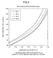
- Fig. 5 shows the results of excitation characteristic tests of iron loss with the respective iron cores No. 1 to No. 4 in Fig. 4, where the horizontal axis shows a magnetic flux density and the vertical axis shows a relative value of iron loss.
- the magnetic flux density is changed from 1.55 T to 1.85 T, the characteristic of iron loss deteriorates in order of No. 2, No. 1, No. 3 and No. 4.
- Fig. 6 shows a comparison between the respective iron loss values at a magnetic flux density of 1.70 T and shows the respective relative values (measured at a frequency of 50 Hz) of iron loss assuming that the iron loss value of No. 1 is 100%.
- the wound iron core No. 2 shows the best iron loss value and shows an improvement of approximately 2% over the iron loss value of the wound iron core made of only the magnetic domain controlled silicon steel sheet 3 of No. 1 at the magnetic flux density of 1.70 T.
- the lamination thickness ratio of the highly oriented silicon steel sheet 2 on the inner periphery side becomes 50% or more, iron loss shows a strong tendency to increase.
- the wound iron core having the lamination thickness ratio of 50% of more has a greater amount of highly oriented silicon steel sheet 2 used and iron loss shows a tendency toward an increase.
- the lamination thickness ratio of the highly oriented silicon steel sheet 3 having a magnetic characteristic inferior to that on the outer periphery side disposed on the inner periphery side is preferably 40% or less.
- Iron loss of the iron core is calculated from the product of the iron loss (W/Kg) characteristic specific to each magnetic steel sheet and the mass used (Kg). Even when magnetic steel sheets of different magnetic characteristics are laminated inside the same iron core, iron loss is believed to be theoretically calculated from the sum of the product of the iron loss (W/Kg) characteristic specific to each magnetic steel sheet and the mass used (Kg). However, it has been verified that by disposing a magnetic steel sheet having a magnetic characteristic inferior to that on the outer periphery side on the inner periphery side of the wound iron core at an appropriate lamination thickness ratio, it is possible to make uniform the magnetic flux distribution in the sectional area of the iron core and obtain a smaller iron loss value than the aforementioned theoretical value of iron loss. Thus, it is possible to manufacture a low cost wound iron core with a reduced rate of increase of iron loss even when a magnetic steel sheet which is low cost and having an inferior magnetic characteristic is used on the inner periphery side of the wound iron core.
- Fig. 7 shows a three-phase three-leg wound iron core made up of two inner wound iron cores 5a and one outside wound iron core 6a disposed so as to surround the two inner wound iron cores, which is a wound iron core made up of directional silicon steel sheets 7a, 9a disposed on the inner periphery side of each wound iron core and highly oriented silicon steel sheets 8a, 10a having a magnetic characteristic superior to that of the directional silicon steel sheet disposed on the outer periphery side.
- both the inside iron core 5a and outside iron core 6a are disposed such that both lamination thickness ratios of the directional silicon steel sheets 7a, 9a on the inner periphery side of each wound iron core are 25%.
- the ratio of the directional silicon steel sheet is 25% for all legs.
- the three-phase three-leg wound iron core in Fig. 8 is made up of two inside wound iron cores 5b and one outside wound iron core 6b disposed so as to surround the two inside wound iron cores and a directional silicon steel sheet 7b is disposed on the inner periphery side of the inside wound iron core 5b, a highly oriented silicon steel sheet 8b is disposed on the outer periphery side, a highly oriented silicon steel sheet 10b is disposed on the inner periphery side of the outside wound iron core 6b and a directional silicon steel sheet 9b is disposed on the outer periphery side.
- the lamination thickness ratio of the directional silicon steel sheet 7b disposed on the inner periphery side of the inside wound iron core 5b is 25% and the lamination thickness ratio of the directional silicon steel sheet 9b disposed on the outer periphery side of the outside wound iron core 6b is 25%. Furthermore, with regard to the lamination thickness ratio of the U-leg, V-leg and W-leg as a whole in the three-phase three-leg wound iron core in Fig. 8, the ratio of the directional silicon steel sheet is 25% for all legs.
- the three-phase three-leg wound iron core in Fig. 9 is made up of two inside wound iron cores 5c and one outside wound iron core 6c disposed so as to surround the two inside wound iron cores and a directional silicon steel sheet 7c is disposed on the inner periphery side of the inside wound iron core 5c, a highly oriented silicon steel sheet 8c is disposed on the outer periphery side, a highly oriented silicon steel sheet 10c is disposed for all the outside wound iron cores 6c.
- the inside wound iron core 5c is disposed such that the lamination thickness ratio of the directional silicon steel sheet 7c disposed on the inner periphery side is 50%.
- the lamination thickness ratios of the U-leg, V-leg and W-leg as a whole in the three-phase three-leg wound iron core in Fig. 9 are U-leg 25%, V-leg 50% and W-leg 25% in the lamination thickness ratio of the directional silicon steel sheet.
- Iron loss of the iron core is calculated from the product of the iron loss (W/Kg) characteristic specific to each magnetic steel sheet and the amount of mass used (Kg). Iron loss of the iron core is believed to be theoretically calculated from the sum of the product of the iron loss (W/Kg) characteristic specific to each magnetic steel sheet and the amount of mass used (Kg) even when magnetic steel sheets of different magnetic characteristics are laminated inside the same iron core.
- the magnetic steel sheet having a magnetic characteristic inferior to that on the outer periphery side on the inner periphery side of the wound iron core at an arbitrary ratio of lamination thickness, it is possible to obtain an iron loss value smaller than the theoretical value of iron loss calculated above and manufacture a low cost wound iron core with a suppressed increase rate of iron loss while using a low cost magnetic steel sheet having an inferior magnetic characteristic.
- Fig. 10 shows a stationary apparatus 11 provided with the above described wound iron core, that is, a wound iron core made up of magnetic steel sheets having a magnetic characteristic inferior to that on the outer periphery side disposed on the inner periphery side having a shorter magnetic path and smaller magnetic resistance and magnetic steel sheets having a magnetic characteristic superior to that on the inner periphery side disposed on the outer periphery side having a longer magnetic path and greater magnetic resistance.
- the stationary apparatus 11 provided with an iron core which is the above described stationary apparatus provided with a wound iron core made up of magnetic steel sheets having a magnetic characteristic inferior to that on the outer periphery side disposed on the inner periphery side having a shorter magnetic path and smaller magnetic resistance so as to account for 40% or less of the total lamination thickness and magnetic steel sheets having a magnetic characteristic superior to that on the inner periphery side disposed on the outer periphery side is shown.
- the stationary apparatus 11 provided with an iron core which is the above described stationary apparatus, wherein a highly oriented silicon steel sheet is used as the magnetic steel sheet on the inner periphery side of the wound iron core and a magnetic domain controlled silicon steel sheet is used as the magnetic steel sheet on the outer periphery side is shown.
- the stationary apparatus 11 provided with a three-phase three-leg wound iron core, which is a stationary apparatus provided with a three-phase three-leg wound iron core made up of 2 inner iron core legs and 1 outer iron core leg, wherein each iron core is formed so that at least one leg of U-leg, V-leg and W-leg is a combination of magnetic steel sheets having different magnetic characteristics and each iron core is formed so that the magnetic material having an inferior magnetic characteristic accounts for 50% or less of the total lamination thickness of one leg is shown.
Landscapes
- Engineering & Computer Science (AREA)
- Power Engineering (AREA)
- Soft Magnetic Materials (AREA)
- Iron Core Of Rotating Electric Machines (AREA)
Abstract
Description
- The present invention relates to a wound iron core for a stationary apparatus such as a transformer or reactor, or more particularly, to a wound iron core made up of magnetic steel sheets having a magnetic characteristic (hereinafter refers to iron loss, magnetic permeability) laminated inside the same iron core at an arbitrary distribution ratio of lamination thickness and a stationary apparatus including such a wound iron core.
- Magnetic steel sheets of an identical type having an identical magnetic characteristic are laminated inside the same iron core of a wound iron core for a transformer. As part of measures against global warming, there is a tendency toward low loss transformers in recent years, and in order to reduce iron loss (non-load loss) generated in an iron core or copper loss (load loss) generated in a coil, the former is designed to increase the amount of magnetic steel sheet used and secure a greater sectional area of the iron core to thereby reduce a magnetic flux density or use an expensive low loss magnetic steel sheet, which leads to upsizing of iron cores and increases in cost.
- Furthermore, Patent Document 1 (
JP-A-10-270263 - It is generally known that magnetic flux in a magnetic flux distribution inside a wound iron core for a stationary apparatus is mal-distributed toward the inner periphery side where the magnetic path of laminated magnetic steel sheets is short and magnetic resistance is small. Thus, the magnetic flux density becomes higher and iron loss deteriorates on the inner periphery side of the wound iron core where magnetic flux is concentrated, and therefore it is important to make uniform the magnetic flux distribution inside the wound iron core in realizing low loss.
- It is an object of the present invention to provide an iron core for a stationary apparatus with magnetic steel sheets of different magnetic characteristics arranged at an arbitrary ratio of lamination thickness to make uniform a magnetic flux distribution inside the same wound iron core.
- In order to solve the above described problems, the present invention disposes a magnetic steel sheet having a magnetic characteristic inferior to that on an outer periphery side on an inner periphery side having a shorter magnetic path and smaller magnetic resistance and disposes a magnetic steel sheet having a magnetic characteristic superior to that on the inner periphery side on the outer periphery side having a longer magnetic path and greater magnetic resistance to thereby make uniform the magnetic flux distribution in a sectional area of the iron core, prevent the magnetic flux density on the inner periphery side of the wound iron core from increasing and improve iron loss.
- Furthermore, the wound iron core for a stationary apparatus according to the present invention is characterized in that the magnetic steel sheet having a magnetic characteristic inferior to that on the outer periphery side is disposed on the inner periphery side having a shorter magnetic path and smaller magnetic resistance such that the thickness thereof accounts for 40% or less of the total lamination thickness of the wound iron core and the magnetic steel sheet having a magnetic characteristic superior to that on the inner periphery side is disposed on the outer periphery side.
- Furthermore, the wound iron core for a stationary apparatus according to the present invention is characterized in that a highly oriented silicon steel sheet is used for the magnetic steel sheet on the inner periphery side of the wound iron core and a magnetic domain controlled silicon steel sheet is used for the magnetic steel sheets on the outer periphery side thereof.
- Furthermore, the three-phase three-leg wound iron core made up of 2 inner iron core legs and 1 outer iron core leg is characterized in that each iron core is formed so that at least one leg of U-leg, V-leg and W-leg is made of a combination of magnetic steel sheets of different magnetic characteristics and each iron core is formed so that a magnetic material having an inferior magnetic characteristic accounts for 50% or less of the total lamination thickness of one leg.
- Furthermore, the stationary apparatus provided with a wound iron core made up of laminated magnetic steel sheets is characterized in that a magnetic steel sheet having a magnetic characteristic inferior to that on the outer periphery side is disposed on the inner periphery side having a shorter magnetic path and smaller magnetic resistance and a magnetic steel sheet having a magnetic characteristic superior to that on the inner periphery side is disposed on the outer periphery side having a longer magnetic path and greater magnetic resistance.
- Furthermore, the above described stationary apparatus is characterized in that the magnetic steel sheet having a magnetic characteristic inferior to that on the outer periphery side is disposed on the inner periphery side having a shorter magnetic path and smaller magnetic resistance such that the thickness thereof accounts for 40% or less of the total lamination thickness of the wound iron core and the magnetic steel sheet having a magnetic characteristic superior to that on the inner periphery side is disposed on the outer periphery side.
- Furthermore, the above described stationary apparatus is characterized in that a highly oriented silicon steel sheet is used for the magnetic steel sheet on the inner periphery side of the wound iron core and a magnetic domain controlled silicon steel sheet is used for the magnetic steel sheet on the outer periphery side thereof.
- Furthermore, the above described stationary apparatus is characterized in that the three-phase three-leg wound iron core made up of 2 inner iron core legs and 1 outer iron core leg is characterized in that each iron core is formed so that at least one leg of U-leg, V-leg and W-leg is made of a combination of magnetic steel sheets of different magnetic characteristics and each iron core is formed so that a magnetic material having an inferior magnetic characteristic accounts for 50% or less of the total lamination thickness of one leg.
- Other objects, features and advantages of the invention will become apparent from the following description of the embodiments of the invention taken in conjunction with the accompanying drawings.
-
- Fig. 1 is a perspective view showing the structure of a wound iron core according to the present invention;
- Fig. 2 is a perspective view showing the structure of a conventional wound iron core;
- Fig. 3 is a diagram showing a magnetic flux distribution of the conventional wound iron core;
- Fig. 4 is a front view of an iron core for characteristic verification according to the present invention;
- Fig. 5 illustrates an iron loss characteristic verification result according to the present invention;
- Fig. 6 is an iron loss characteristic comparative diagram at 1.70 T according to the present invention;
- Fig. 7 is a front view showing an embodiment of a three-phase three-leg wound iron core according to the present invention;
- Fig. 8 is a front view showing another embodiment of the three-phase three-leg wound iron core according to the present invention;
- Fig. 9 is a front view showing a further embodiment of the three-phase three-leg wound iron core according to the present invention; and
- Fig. 10 illustrates a stationary apparatus (transformer) mounted with the wound iron core according to the present invention.
- With reference now to the attached drawings, embodiments of a wound iron core structure according to the present invention will be explained below.
- Conventionally, a wound iron core for a transformer is manufactured with magnetic steel sheets of an identical type having an identical magnetic characteristic laminated inside the same iron core as shown in Fig. 2. And magnetic flux in a magnetic flux distribution inside this
wound iron core 4 is mal-distributed toward the inner periphery side having a shorter magnetic path and smaller magnetic resistance of magnetic steel sheets laminated as shown in Fig. 3. Therefore, the inner periphery side of the wound iron core on which magnetic flux is concentrated has a high magnetic flux density and its iron loss increases. - Therefore, the present invention adopts a wound iron core having such a structure that a magnetic steel sheet having an inferior magnetic characteristic is disposed on the inner periphery side having a shorter magnetic path and a magnetic steel sheet having a magnetic characteristic superior to that on the inner periphery side is disposed on the outer periphery side having a longer magnetic path to thereby make uniform the magnetic flux distribution in a sectional area of the iron core.
- Fig. 1 shows a
wound iron core 1 manufactured using two types of magnetic steel sheets having different magnetic characteristics, which is a wound iron core made up of a highly orientedsilicon steel sheet 2 disposed on the inner periphery side of thewound iron core 1 and a magnetic domain controlledsilicon steel sheet 3 having a magnetic characteristic superior to that of the highly orientedsilicon steel sheet 2 on the outer periphery side. Here, the "highly oriented silicon steel sheet" means a silicon steel sheet in which the rolling direction of the material matches the direction in which magnetic flux passes. The "magnetic domain controlled silicon steel sheet" means a silicon steel sheet made of a highly oriented silicon steel sheet as a raw material, on the surface of which shallow grooves are formed to fragment its magnetic domain and the magnetic characteristic of which is superior to that of the highly oriented silicon steel sheet. With regard to this wound iron core structure, various structures with different lamination thickness ratios between themagnetic steel sheets silicon steel sheet 3 for a characteristic comparison of iron loss. In contrast to this, the wound iron core No. 2 is made up of the highly orientedsilicon steel sheet 2 disposed on the inner periphery side at a lamination thickness ratio of 25% and a magnetic domain controlledsilicon steel sheet 3 having a magnetic characteristic superior to that of the highly orientedsilicon steel sheet 2 disposed on the outer periphery side at a lamination thickness ratio of 75%. The wound iron cores No. 3 and No. 4 are made up of the highly orientedsilicon steel sheet 2 disposed on the inner periphery side at lamination thickness ratios of 50% and 75% respectively in the same way as for No. 2. Hereinafter, verification results of the iron loss characteristics of these wound iron cores will be explained. - Fig. 5 shows the results of excitation characteristic tests of iron loss with the respective iron cores No. 1 to No. 4 in Fig. 4, where the horizontal axis shows a magnetic flux density and the vertical axis shows a relative value of iron loss. In Fig. 5, it can be appreciated that when the magnetic flux density is changed from 1.55 T to 1.85 T, the characteristic of iron loss deteriorates in order of No. 2, No. 1, No. 3 and No. 4.
- Furthermore, Fig. 6 shows a comparison between the respective iron loss values at a magnetic flux density of 1.70 T and shows the respective relative values (measured at a frequency of 50 Hz) of iron loss assuming that the iron loss value of No. 1 is 100%. In Fig. 6, the wound iron core No. 2 shows the best iron loss value and shows an improvement of approximately 2% over the iron loss value of the wound iron core made of only the magnetic domain controlled
silicon steel sheet 3 of No. 1 at the magnetic flux density of 1.70 T. Furthermore, when the lamination thickness ratio of the highly orientedsilicon steel sheet 2 on the inner periphery side becomes 50% or more, iron loss shows a strong tendency to increase. - It is generally known that magnetic flux in a wound iron core is mal-distributed toward an inner periphery side having a shorter magnetic path with respect to the total lamination thickness and smaller magnetic resistance. In this verification, the highly oriented
silicon steel sheet 2 is disposed on the inner periphery side of the wound iron core and the magnetic domain controlledsilicon steel sheet 3 having a magnetic characteristic superior to that of the highly orientedsilicon steel sheet 2, that is, higher magnetic permeability is disposed on the outer periphery side, and the magnetic flux distribution in the sectional area of the iron core is thereby made uniform and iron loss improved. However, from this test result, it can be confirmed that even when the highly orientedsilicon steel sheet 2 having a magnetic characteristic inferior to that on the outer periphery side is disposed on the inner periphery side, the wound iron core having the lamination thickness ratio of 50% of more has a greater amount of highly orientedsilicon steel sheet 2 used and iron loss shows a tendency toward an increase. From above, the lamination thickness ratio of the highly orientedsilicon steel sheet 3 having a magnetic characteristic inferior to that on the outer periphery side disposed on the inner periphery side is preferably 40% or less. - Iron loss of the iron core is calculated from the product of the iron loss (W/Kg) characteristic specific to each magnetic steel sheet and the mass used (Kg). Even when magnetic steel sheets of different magnetic characteristics are laminated inside the same iron core, iron loss is believed to be theoretically calculated from the sum of the product of the iron loss (W/Kg) characteristic specific to each magnetic steel sheet and the mass used (Kg). However, it has been verified that by disposing a magnetic steel sheet having a magnetic characteristic inferior to that on the outer periphery side on the inner periphery side of the wound iron core at an appropriate lamination thickness ratio, it is possible to make uniform the magnetic flux distribution in the sectional area of the iron core and obtain a smaller iron loss value than the aforementioned theoretical value of iron loss. Thus, it is possible to manufacture a low cost wound iron core with a reduced rate of increase of iron loss even when a magnetic steel sheet which is low cost and having an inferior magnetic characteristic is used on the inner periphery side of the wound iron core.
- Fig. 7 shows a three-phase three-leg wound iron core made up of two inner
wound iron cores 5a and one outsidewound iron core 6a disposed so as to surround the two inner wound iron cores, which is a wound iron core made up of directionalsilicon steel sheets silicon steel sheets iron core 5a andoutside iron core 6a are disposed such that both lamination thickness ratios of the directionalsilicon steel sheets - The three-phase three-leg wound iron core in Fig. 8 is made up of two inside
wound iron cores 5b and one outsidewound iron core 6b disposed so as to surround the two inside wound iron cores and a directionalsilicon steel sheet 7b is disposed on the inner periphery side of the insidewound iron core 5b, a highly orientedsilicon steel sheet 8b is disposed on the outer periphery side, a highly orientedsilicon steel sheet 10b is disposed on the inner periphery side of the outsidewound iron core 6b and a directionalsilicon steel sheet 9b is disposed on the outer periphery side. The three-phase three-leg wound iron core in Fig. 8 is arranged such that the lamination thickness ratio of the directionalsilicon steel sheet 7b disposed on the inner periphery side of the insidewound iron core 5b is 25% and the lamination thickness ratio of the directionalsilicon steel sheet 9b disposed on the outer periphery side of the outsidewound iron core 6b is 25%. Furthermore, with regard to the lamination thickness ratio of the U-leg, V-leg and W-leg as a whole in the three-phase three-leg wound iron core in Fig. 8, the ratio of the directional silicon steel sheet is 25% for all legs. - The three-phase three-leg wound iron core in Fig. 9 is made up of two inside
wound iron cores 5c and one outsidewound iron core 6c disposed so as to surround the two inside wound iron cores and a directionalsilicon steel sheet 7c is disposed on the inner periphery side of the insidewound iron core 5c, a highly orientedsilicon steel sheet 8c is disposed on the outer periphery side, a highly orientedsilicon steel sheet 10c is disposed for all the outsidewound iron cores 6c. Note that the insidewound iron core 5c is disposed such that the lamination thickness ratio of the directionalsilicon steel sheet 7c disposed on the inner periphery side is 50%. Furthermore, the lamination thickness ratios of the U-leg, V-leg and W-leg as a whole in the three-phase three-leg wound iron core in Fig. 9 are U-leg 25%, V-leg 50% and W-leg 25% in the lamination thickness ratio of the directional silicon steel sheet. - Iron loss of the iron core is calculated from the product of the iron loss (W/Kg) characteristic specific to each magnetic steel sheet and the amount of mass used (Kg). Iron loss of the iron core is believed to be theoretically calculated from the sum of the product of the iron loss (W/Kg) characteristic specific to each magnetic steel sheet and the amount of mass used (Kg) even when magnetic steel sheets of different magnetic characteristics are laminated inside the same iron core.
- However, according to the present invention, by disposing the magnetic steel sheet having a magnetic characteristic inferior to that on the outer periphery side on the inner periphery side of the wound iron core at an arbitrary ratio of lamination thickness, it is possible to obtain an iron loss value smaller than the theoretical value of iron loss calculated above and manufacture a low cost wound iron core with a suppressed increase rate of iron loss while using a low cost magnetic steel sheet having an inferior magnetic characteristic.
- Fig. 10 shows a
stationary apparatus 11 provided with the above described wound iron core, that is, a wound iron core made up of magnetic steel sheets having a magnetic characteristic inferior to that on the outer periphery side disposed on the inner periphery side having a shorter magnetic path and smaller magnetic resistance and magnetic steel sheets having a magnetic characteristic superior to that on the inner periphery side disposed on the outer periphery side having a longer magnetic path and greater magnetic resistance. - Furthermore, the
stationary apparatus 11 provided with an iron core, which is the above described stationary apparatus provided with a wound iron core made up of magnetic steel sheets having a magnetic characteristic inferior to that on the outer periphery side disposed on the inner periphery side having a shorter magnetic path and smaller magnetic resistance so as to account for 40% or less of the total lamination thickness and magnetic steel sheets having a magnetic characteristic superior to that on the inner periphery side disposed on the outer periphery side is shown. - Furthermore, the
stationary apparatus 11 provided with an iron core, which is the above described stationary apparatus, wherein a highly oriented silicon steel sheet is used as the magnetic steel sheet on the inner periphery side of the wound iron core and a magnetic domain controlled silicon steel sheet is used as the magnetic steel sheet on the outer periphery side is shown. - Furthermore, the
stationary apparatus 11 provided with a three-phase three-leg wound iron core, which is a stationary apparatus provided with a three-phase three-leg wound iron core made up of 2 inner iron core legs and 1 outer iron core leg, wherein each iron core is formed so that at least one leg of U-leg, V-leg and W-leg is a combination of magnetic steel sheets having different magnetic characteristics and each iron core is formed so that the magnetic material having an inferior magnetic characteristic accounts for 50% or less of the total lamination thickness of one leg is shown. - It should be further understood by those skilled in the art that although the foregoing description has been made on embodiments of the invention, the invention is not limited thereto and various changes and modifications may be made without departing from the spirit of the invention and the scope of the appended claims.
Claims (8)
- A wound iron core for a stationary apparatus made up of laminated magnetic steel sheets, comprising a first magnetic steel sheet (2) disposed on an inner periphery side and a second magnetic steel sheet (3) disposed on an outer periphery side, said inner periphery side having a shorter magnetic path and smaller magnetic resistance and said outer periphery side having a longer magnetic path and greater magnetic resistance, characterized in that:said first magnetic steel sheet (2) has a magnetic characteristic inferior to that of said second magnetic steel sheet (3); andsaid second magnetic steel sheet (3) has a magnetic characteristic superior to that of said first magnetic steel sheet (2).
- The wound iron core for a stationary apparatus according to claim 1, wherein said first magnetic steel sheet (2) is disposed such that the thickness thereof accounts for 40% or less of the total lamination thickness of the wound iron core and said second magnetic steel sheet (3) is disposed on the outer periphery side.
- The wound iron core for a stationary apparatus according to claim 1, wherein a highly oriented silicon steel sheet is used for said first magnetic steel sheet (2) and a magnetic domain controlled silicon steel sheet is used for said second magnetic steel sheet (3).
- A three-phase three-leg wound iron core comprising two inner iron core legs (5a, 5b, 5c) and one outer iron core leg (6a, 6b, 6c),
wherein each iron core is formed so that at least one leg of U-leg, V-leg and W-leg is made of a combination of magnetic steel sheets of different magnetic characteristics, and
each iron core is formed so that a magnetic material having an inferior magnetic characteristic accounts for 50% or less of the total lamination thickness of one leg. - A stationary apparatus provided with a wound iron core made up of laminated magnetic steel sheets, the wound iron core comprising a first magnetic steel sheet (2) disposed on an inner periphery side and a second magnetic steel sheet (3) disposed on an outer periphery side, said inner periphery side having a shorter magnetic path and smaller magnetic resistance and said outer periphery side having a longer magnetic path and greater magnetic resistance, characterized in that:said first magnetic steel sheet (2) has a magnetic characteristic inferior to that of said second magnetic steel sheet (3); andsaid second magnetic steel sheet (3) has a magnetic characteristic superior to that of said first magnetic steel sheet (2).
- The stationary apparatus according to claim 5, wherein said first magnetic steel sheet (2) is disposed such that the thickness thereof accounts for 40% or less of the total lamination thickness of the wound iron core and said second magnetic steel sheet (3) is disposed on the outer periphery side.
- The stationary apparatus according to claim 5, wherein a highly oriented silicon steel sheet is used for said first magnetic steel sheet (2) and a magnetic domain controlled silicon steel sheet is used for said second magnetic steel sheet (3).
- A stationary apparatus comprising a three-phase three-leg wound iron core made up of two inner iron core legs (5a, 5b, 5c) and one outer iron core leg(6a, 6b, 6c),
wherein each iron core is formed so that at least one leg of U-leg, V-leg and W-leg is made of a combination of magnetic steel sheets of different magnetic characteristics, and
each iron core is formed so that a magnetic material having an inferior magnetic characteristic accounts for 50% or less of the total lamination thickness of one leg.
Applications Claiming Priority (2)
| Application Number | Priority Date | Filing Date | Title |
|---|---|---|---|
| JP2005199545 | 2005-07-08 | ||
| JP2005289510A JP4959170B2 (en) | 2005-07-08 | 2005-10-03 | Iron core for stationary equipment |
Publications (3)
| Publication Number | Publication Date |
|---|---|
| EP1742232A2 true EP1742232A2 (en) | 2007-01-10 |
| EP1742232A3 EP1742232A3 (en) | 2011-09-21 |
| EP1742232B1 EP1742232B1 (en) | 2016-05-18 |
Family
ID=37038300
Family Applications (1)
| Application Number | Title | Priority Date | Filing Date |
|---|---|---|---|
| EP06013868.2A Ceased EP1742232B1 (en) | 2005-07-08 | 2006-07-04 | Iron core for stationary apparatus and stationary apparatus |
Country Status (3)
| Country | Link |
|---|---|
| US (2) | US7675398B2 (en) |
| EP (1) | EP1742232B1 (en) |
| JP (1) | JP4959170B2 (en) |
Cited By (1)
| Publication number | Priority date | Publication date | Assignee | Title |
|---|---|---|---|---|
| WO2016083866A1 (en) * | 2014-11-25 | 2016-06-02 | Aperam | Basic module for magnetic core of an electrical transformer, magnetic core comprising said basic module, method for manufacturing said magnetic core, and transformer comprising said magnetic core |
Families Citing this family (11)
| Publication number | Priority date | Publication date | Assignee | Title |
|---|---|---|---|---|
| CN1897175B (en) * | 2005-07-08 | 2012-07-18 | 株式会社日立产机系统 | Iron core for stationary apparatus and stationary apparatus |
| JP5216536B2 (en) * | 2008-11-05 | 2013-06-19 | 株式会社日立産機システム | Iron core for stationary equipment |
| JP5333169B2 (en) * | 2009-11-20 | 2013-11-06 | 株式会社デンソー | Reactor |
| JP2012204745A (en) * | 2011-03-28 | 2012-10-22 | Kitashiba Electric Co Ltd | Iron core reactor |
| DE102012206225A1 (en) * | 2012-04-16 | 2013-10-17 | Vacuumschmelze Gmbh & Co. Kg | Soft magnetic core with location-dependent permeability |
| JP5945002B2 (en) * | 2012-10-17 | 2016-07-05 | 株式会社日立製作所 | Transformers and converters |
| US9633778B2 (en) * | 2014-11-21 | 2017-04-25 | Hamilton Sundstrand Corporation | Magnetic component with balanced flux distribution |
| JP7009937B2 (en) * | 2017-11-06 | 2022-01-26 | 日本製鉄株式会社 | BF estimation method for winding core |
| CN108399995B (en) * | 2018-02-09 | 2021-01-29 | 宁波耀峰液压电器有限公司 | Magnetic protection type electromagnet |
| JP7167779B2 (en) * | 2019-03-12 | 2022-11-09 | 日本製鉄株式会社 | Method for manufacturing iron core, wound iron core, method for manufacturing stacked iron core, and method for manufacturing electromagnetic steel sheet for iron core |
| JP7372549B2 (en) * | 2020-04-03 | 2023-11-01 | 日本製鉄株式会社 | Wound iron core, wound iron core manufacturing method, and wound iron core manufacturing device |
Family Cites Families (26)
| Publication number | Priority date | Publication date | Assignee | Title |
|---|---|---|---|---|
| GB624040A (en) * | 1946-03-28 | 1949-05-26 | British Thomson Houston Co Ltd | Improvements in and relating to magnetic cores |
| US2498475A (en) * | 1948-05-06 | 1950-02-21 | Gen Electric | Saturable magnetic core |
| US3025483A (en) * | 1953-11-16 | 1962-03-13 | Gen Electric | Magnetic core |
| US2908880A (en) * | 1955-08-08 | 1959-10-13 | Mc Graw Edison Co | Magnetic core |
| US2912660A (en) * | 1957-05-13 | 1959-11-10 | Gen Electric | T-joint for a magnetic core |
| US2982948A (en) * | 1957-11-01 | 1961-05-02 | Ibm | Multi-material ferrite cores |
| US2968778A (en) * | 1959-10-29 | 1961-01-17 | Mc Graw Edison Co | Three-legged magnetic core |
| US3290633A (en) * | 1961-12-14 | 1966-12-06 | Hitachi Ltd | Laminated core with bidirectional joints |
| US3339163A (en) * | 1965-01-29 | 1967-08-29 | Westinghouse Electric Corp | Split or separable core current transformers |
| US3454916A (en) * | 1967-10-09 | 1969-07-08 | Granger Associates | Transformer core construction |
| US4205288A (en) * | 1978-10-27 | 1980-05-27 | Westinghouse Electric Corp. | Transformer with parallel magnetic circuits of unequal mean lengths and loss characteristics |
| US4274071A (en) * | 1979-11-16 | 1981-06-16 | Bell Telephone Laboratories, Incorporated | Three-phase ferroresonant transformer structure embodied in one unitary transformer construction |
| JPS5875813A (en) * | 1981-10-30 | 1983-05-07 | Mitsubishi Electric Corp | Core for stationary induction apparatus |
| US4520335A (en) * | 1983-04-06 | 1985-05-28 | Westinghouse Electric Corp. | Transformer with ferromagnetic circuits of unequal saturation inductions |
| US4585746A (en) * | 1984-06-27 | 1986-04-29 | Mobil Oil Corporation | Synthesis of crystalline silicate ZSM-12 |
| JPS6115309A (en) | 1984-07-02 | 1986-01-23 | Kawasaki Steel Corp | Wound core for transformer with low iron loss |
| US4789849A (en) * | 1985-12-04 | 1988-12-06 | General Electric Company | Amorphous metal transformer core and coil assembly |
| JPH0461211A (en) * | 1990-06-29 | 1992-02-27 | Toshiba Corp | Magnetic iron core |
| US5371486A (en) * | 1990-09-07 | 1994-12-06 | Kabushiki Kaisha Toshiba | Transformer core |
| JPH06120044A (en) * | 1991-04-17 | 1994-04-28 | Nippon Steel Corp | Low-noise transformer core |
| JPH05101943A (en) | 1991-05-08 | 1993-04-23 | Toshiba Corp | Three-phase wound core |
| JP3317045B2 (en) * | 1994-10-14 | 2002-08-19 | 株式会社村田製作所 | Common mode choke coil |
| TW371768B (en) * | 1997-06-06 | 1999-10-11 | Hitachi Ltd | Amorphous transformer |
| CN1220473A (en) | 1997-12-18 | 1999-06-23 | 杨鹤年 | Polygonal section rolling-up iron core transformer |
| JP3483459B2 (en) | 1998-03-24 | 2004-01-06 | 株式会社日立産機システム | Amorphous transformer |
| JP2003142318A (en) | 2001-11-01 | 2003-05-16 | Hitachi Ltd | Gas-insulated transformer |
-
2005
- 2005-10-03 JP JP2005289510A patent/JP4959170B2/en active Active
-
2006
- 2006-07-04 EP EP06013868.2A patent/EP1742232B1/en not_active Ceased
- 2006-07-07 US US11/481,865 patent/US7675398B2/en not_active Expired - Fee Related
-
2009
- 2009-11-25 US US12/626,149 patent/US8258912B2/en active Active
Non-Patent Citations (1)
| Title |
|---|
| None |
Cited By (2)
| Publication number | Priority date | Publication date | Assignee | Title |
|---|---|---|---|---|
| WO2016083866A1 (en) * | 2014-11-25 | 2016-06-02 | Aperam | Basic module for magnetic core of an electrical transformer, magnetic core comprising said basic module, method for manufacturing said magnetic core, and transformer comprising said magnetic core |
| US10515756B2 (en) | 2014-11-25 | 2019-12-24 | Aperam | Basic module for magnetic core of an electrical transformer, magnetic core comprising said basic module, method for manufacturing said magnetic core, and transformer comprising said magnetic core |
Also Published As
| Publication number | Publication date |
|---|---|
| US20080272876A1 (en) | 2008-11-06 |
| JP2007043040A (en) | 2007-02-15 |
| JP4959170B2 (en) | 2012-06-20 |
| EP1742232A3 (en) | 2011-09-21 |
| US20100066476A1 (en) | 2010-03-18 |
| US8258912B2 (en) | 2012-09-04 |
| US7675398B2 (en) | 2010-03-09 |
| EP1742232B1 (en) | 2016-05-18 |
Similar Documents
| Publication | Publication Date | Title |
|---|---|---|
| EP1742232B1 (en) | Iron core for stationary apparatus and stationary apparatus | |
| JP5544393B2 (en) | Winding iron core for stationary equipment and stationary equipment having the same | |
| KR101553497B1 (en) | Grain-oriented electrical steel sheet and method for manufacturing same | |
| US20140373340A1 (en) | Non-grain-oriented higher-strength electrical strip with high polarisation and method for the production thereof | |
| KR102380300B1 (en) | Multilayer electrical steel sheet | |
| JP2010132938A (en) | Clad type electromagnetic steel sheet | |
| JP2018157142A (en) | Selection method of grain-oriented electromagnetic steel sheet and manufacturing method of wound core | |
| JP2019087619A (en) | Bf estimation method of wound core | |
| KR102394521B1 (en) | Multilayer electrical steel sheet | |
| CA2752327A1 (en) | Economical core design for electromagnetic devices | |
| KR20160081493A (en) | A core for transformer | |
| US20160240307A1 (en) | Coil component, high current indcutor, high current reactor inlcuding the same | |
| CN101086913B (en) | Transformer | |
| JP4249594B2 (en) | Transformers and transformer cores | |
| JPH03204911A (en) | Transformer core | |
| JPH03236204A (en) | Iron core for three-phase transformer | |
| JP6491835B2 (en) | Static induction machine | |
| JP2018117046A (en) | Transformer | |
| CN202205553U (en) | Iron core | |
| CN218482076U (en) | Annular iron core and annular transformer thereof | |
| JP2005307258A (en) | Nonoriented silicon steel sheet having reduced deterioration in core loss caused by compressive stress and its production method | |
| JP3823418B2 (en) | Core with gap for reactor | |
| JP2003077735A (en) | Amorphous core transformer | |
| KR20200092392A (en) | Double-layered electrical steel sheet | |
| KR200378049Y1 (en) | Transformer cut core |
Legal Events
| Date | Code | Title | Description |
|---|---|---|---|
| PUAI | Public reference made under article 153(3) epc to a published international application that has entered the european phase |
Free format text: ORIGINAL CODE: 0009012 |
|
| AK | Designated contracting states |
Kind code of ref document: A2 Designated state(s): AT BE BG CH CY CZ DE DK EE ES FI FR GB GR HU IE IS IT LI LT LU LV MC NL PL PT RO SE SI SK TR |
|
| AX | Request for extension of the european patent |
Extension state: AL BA HR MK YU |
|
| 17P | Request for examination filed |
Effective date: 20080331 |
|
| PUAL | Search report despatched |
Free format text: ORIGINAL CODE: 0009013 |
|
| AK | Designated contracting states |
Kind code of ref document: A3 Designated state(s): AT BE BG CH CY CZ DE DK EE ES FI FR GB GR HU IE IS IT LI LT LU LV MC NL PL PT RO SE SI SK TR |
|
| AX | Request for extension of the european patent |
Extension state: AL BA HR MK RS |
|
| RIC1 | Information provided on ipc code assigned before grant |
Ipc: H01F 27/25 20060101ALI20110817BHEP Ipc: H01F 3/04 20060101AFI20110817BHEP |
|
| AKX | Designation fees paid |
Designated state(s): DE |
|
| 17Q | First examination report despatched |
Effective date: 20130208 |
|
| GRAP | Despatch of communication of intention to grant a patent |
Free format text: ORIGINAL CODE: EPIDOSNIGR1 |
|
| INTG | Intention to grant announced |
Effective date: 20151201 |
|
| GRAS | Grant fee paid |
Free format text: ORIGINAL CODE: EPIDOSNIGR3 |
|
| GRAA | (expected) grant |
Free format text: ORIGINAL CODE: 0009210 |
|
| AK | Designated contracting states |
Kind code of ref document: B1 Designated state(s): DE |
|
| REG | Reference to a national code |
Ref country code: DE Ref legal event code: R096 Ref document number: 602006049102 Country of ref document: DE |
|
| REG | Reference to a national code |
Ref country code: DE Ref legal event code: R097 Ref document number: 602006049102 Country of ref document: DE |
|
| PLBE | No opposition filed within time limit |
Free format text: ORIGINAL CODE: 0009261 |
|
| STAA | Information on the status of an ep patent application or granted ep patent |
Free format text: STATUS: NO OPPOSITION FILED WITHIN TIME LIMIT |
|
| 26N | No opposition filed |
Effective date: 20170221 |
|
| PGFP | Annual fee paid to national office [announced via postgrant information from national office to epo] |
Ref country code: DE Payment date: 20200624 Year of fee payment: 15 |
|
| REG | Reference to a national code |
Ref country code: DE Ref legal event code: R119 Ref document number: 602006049102 Country of ref document: DE |
|
| PG25 | Lapsed in a contracting state [announced via postgrant information from national office to epo] |
Ref country code: DE Free format text: LAPSE BECAUSE OF NON-PAYMENT OF DUE FEES Effective date: 20220201 |