EP1742218A2 - Forming visual image on optical disk by laser beam - Google Patents
Forming visual image on optical disk by laser beam Download PDFInfo
- Publication number
- EP1742218A2 EP1742218A2 EP06013484A EP06013484A EP1742218A2 EP 1742218 A2 EP1742218 A2 EP 1742218A2 EP 06013484 A EP06013484 A EP 06013484A EP 06013484 A EP06013484 A EP 06013484A EP 1742218 A2 EP1742218 A2 EP 1742218A2
- Authority
- EP
- European Patent Office
- Prior art keywords
- data
- optical disk
- host device
- drive unit
- disk drive
- Prior art date
- Legal status (The legal status is an assumption and is not a legal conclusion. Google has not performed a legal analysis and makes no representation as to the accuracy of the status listed.)
- Granted
Links
Images




Classifications
-
- G—PHYSICS
- G11—INFORMATION STORAGE
- G11B—INFORMATION STORAGE BASED ON RELATIVE MOVEMENT BETWEEN RECORD CARRIER AND TRANSDUCER
- G11B23/00—Record carriers not specific to the method of recording or reproducing; Accessories, e.g. containers, specially adapted for co-operation with the recording or reproducing apparatus ; Intermediate mediums; Apparatus or processes specially adapted for their manufacture
- G11B23/38—Visual features other than those contained in record tracks or represented by sprocket holes the visual signals being auxiliary signals
- G11B23/40—Identifying or analogous means applied to or incorporated in the record carrier and not intended for visual display simultaneously with the playing-back of the record carrier, e.g. label, leader, photograph
-
- G—PHYSICS
- G11—INFORMATION STORAGE
- G11B—INFORMATION STORAGE BASED ON RELATIVE MOVEMENT BETWEEN RECORD CARRIER AND TRANSDUCER
- G11B19/00—Driving, starting, stopping record carriers not specifically of filamentary or web form, or of supports therefor; Control thereof; Control of operating function ; Driving both disc and head
- G11B19/02—Control of operating function, e.g. switching from recording to reproducing
- G11B19/04—Arrangements for preventing, inhibiting, or warning against double recording on the same blank or against other recording or reproducing malfunctions
-
- G—PHYSICS
- G11—INFORMATION STORAGE
- G11B—INFORMATION STORAGE BASED ON RELATIVE MOVEMENT BETWEEN RECORD CARRIER AND TRANSDUCER
- G11B19/00—Driving, starting, stopping record carriers not specifically of filamentary or web form, or of supports therefor; Control thereof; Control of operating function ; Driving both disc and head
- G11B19/20—Driving; Starting; Stopping; Control thereof
- G11B19/28—Speed controlling, regulating, or indicating
-
- G—PHYSICS
- G11—INFORMATION STORAGE
- G11B—INFORMATION STORAGE BASED ON RELATIVE MOVEMENT BETWEEN RECORD CARRIER AND TRANSDUCER
- G11B20/00—Signal processing not specific to the method of recording or reproducing; Circuits therefor
- G11B20/10—Digital recording or reproducing
- G11B20/10527—Audio or video recording; Data buffering arrangements
-
- G—PHYSICS
- G11—INFORMATION STORAGE
- G11B—INFORMATION STORAGE BASED ON RELATIVE MOVEMENT BETWEEN RECORD CARRIER AND TRANSDUCER
- G11B7/00—Recording or reproducing by optical means, e.g. recording using a thermal beam of optical radiation by modifying optical properties or the physical structure, reproducing using an optical beam at lower power by sensing optical properties; Record carriers therefor
- G11B7/002—Recording, reproducing or erasing systems characterised by the shape or form of the carrier
- G11B7/0037—Recording, reproducing or erasing systems characterised by the shape or form of the carrier with discs
-
- G—PHYSICS
- G11—INFORMATION STORAGE
- G11B—INFORMATION STORAGE BASED ON RELATIVE MOVEMENT BETWEEN RECORD CARRIER AND TRANSDUCER
- G11B20/00—Signal processing not specific to the method of recording or reproducing; Circuits therefor
- G11B20/10—Digital recording or reproducing
- G11B20/10527—Audio or video recording; Data buffering arrangements
- G11B2020/1062—Data buffering arrangements, e.g. recording or playback buffers
- G11B2020/10675—Data buffering arrangements, e.g. recording or playback buffers aspects of buffer control
-
- G—PHYSICS
- G11—INFORMATION STORAGE
- G11B—INFORMATION STORAGE BASED ON RELATIVE MOVEMENT BETWEEN RECORD CARRIER AND TRANSDUCER
- G11B20/00—Signal processing not specific to the method of recording or reproducing; Circuits therefor
- G11B20/10—Digital recording or reproducing
- G11B20/10527—Audio or video recording; Data buffering arrangements
- G11B2020/1062—Data buffering arrangements, e.g. recording or playback buffers
- G11B2020/10814—Data buffering arrangements, e.g. recording or playback buffers involving specific measures to prevent a buffer underrun
-
- G—PHYSICS
- G11—INFORMATION STORAGE
- G11B—INFORMATION STORAGE BASED ON RELATIVE MOVEMENT BETWEEN RECORD CARRIER AND TRANSDUCER
- G11B2220/00—Record carriers by type
- G11B2220/20—Disc-shaped record carriers
- G11B2220/25—Disc-shaped record carriers characterised in that the disc is based on a specific recording technology
- G11B2220/2537—Optical discs
Definitions
- the present invention relates to an optical disk recording system which forms a visible image on a disk surface of an optical disk, such as a CR-R/RW, a DVD+R/RW, or a DVD-R/RW, by use of a laser.
- an optical disk recording system which forms a visible image on a disk surface of an optical disk, such as a CR-R/RW, a DVD+R/RW, or a DVD-R/RW, by use of a laser.
- Patent Document 1 proposes a technique of providing a visible light characteristic changing layer at a position which is viewable from a label surface side of an optical disk; and exposing the visible light characteristic changing layer to a laser beam to thus change a visible light characteristic of the layer and render a visible image.
- Patent Document 2 proposes a technique of using a reversible phase change material for a recording film of an optical disk, which enables recording of a visible image by use of a laser, and rewriting recorded graphics.
- Patent Document 3 proposes a technique of newly writing a visible image on a recording surface of an optical disk on which a visible image has already been recorded.
- Patent Document 4 proposes a visible image recorder capable of preventing occurrence of a failure of adj acent pixels in a visible image to be recorded at separated positions to thus record a visible image, differing from the original image, which would otherwise be caused when the visible image has been brought out of focus by a servo during recording of a visible image.
- Patent Document 4 also describes, as a way to determine an angle position ⁇ , a technique of determining a single rotation from a predetermined number of cycles; generating a pulse signal every predetermined number of cycles; and determining an angle position by means of the number of pulses (Fig. 6).
- Patent Document 1 JP-A-2002-203321
- Patent Document 2 JP-A-2003-016649
- Patent Document 3 JP-A-2004-039019
- Patent Document 4 JP-A-2004-030832
- the present invention aims at providing an optical disk recording system which enables visually-smooth rendering even when rendering has been interrupted as a result of occurrence of "buffer under run” or when occurrence of "buffer under run” is predicted.
- the present invention is characterized by having the following arrangements.
- an optical recording system of the present invention evenwhen rendering is interrupted as a result of "buffer under run” having arisen because of delayed transfer of image data from host device or even when occurrence of "buffer under run” error is predicted, an angle on a disk where an interruption has arisen is computed, and the host device resumes rendering by means of transferring spliceable rendering data in consideration of the thus-computed angle, to thus make an accurate rendering splice. Even when the processing speed of the host device is not sufficient, visually-smooth rendering is enabled.
- Fig. 1 is a block diagram showing the principal configuration of an embodiment of an optical disk recording system of the present invention.
- the optical disk recording system of the present embodiment comprises an optical disk drive unit 10 which records and reproduces data to and from an optical disk 1 and forms a visible image; and host device 40, such as a host computer, a backend device, or the like, connected to the optical disk drive unit 10.
- the host device 40 is equipped with an image editing program for editing a visible image to be recorded on the optical disk 1, and a control program for recording data and a visible image on the optical disk 1 and reproducing data from the optical disk 1.
- Reference numeral 41 designates buffer memory for temporarily storing data to be transferred from the host device 40 to the optical disk drive unit 10.
- the host device 40 sequentially reads the data stored in the buffer memory 41 and transfers the thus-read data to buffer memory 24 of the optical disk drive unit 10.
- the function of the host device 40 may be imparted to the optical disk drive unit 10.
- the optical disk drive unit 10 comprises a spindle motor 11 for rotationally driving the optical disk 1; a frequency generator 12 for outputting an FGpulse of a frequency responsive to the rotational speed of the spindle; an optical pickup 13; an RF amplifier 14; a servo circuit 15; a decoder 16; an address detection circuit 17; a control portion 18; a stepping motor 19; a motor driver 20; a motor controller 21; a frequency divider circuit 22; an LPC (Laser Power Control) circuit 23 for controlling laser power; the buffer memory 24; an encoder 25; a strategy circuit 26; a laser driver 27 for driving a laser diode of the optical pickup 13; a demodulator circuit 28 and an AND circuit 29 which are used for recording a visible image; and an interface circuit 30 for exchanging data among the control portion 18, the buffer memory 24, and the host device 40.
- a spindle motor 11 for rotationally driving the optical disk 1
- a frequency generator 12 for outputting an FGpulse of a frequency responsive
- the optical pickup 13 radiates a laser beam onto the optical disk 1 to thus record and reproduce data as well as to render a visible image.
- a returned-light reception signal (an RF signal having undergone EFM modulation or 8-to-16 modulation), which is generated upon receipt of the light returned at the time of the laser beam having been radiated onto the optical disk l, is amplified by the RF amplifier 14.
- the thus-amplified signal is supplied to the servo circuit 15, the decoder 16, and the address detection circuit 17.
- the servo circuit 15 controls the rotation of the spindle motor 11 and controls the focus and tracking of the optical pickup 13.
- the decoder 16 demodulates the signal that is supplied from the RF amplifier 14 and has undergone EFM modulation or 8-to-16 modulation, and outputs reproduced data.
- the address detection circuit 17 extracts a wobble signal component from the signal supplied from the RF amplifier 14; demodulates an ADIP (Address In Pre-Groove) of DVD-based specifications or an ATIP (Absolute Time in Pre-Groove) of CD-based specifications; and detects address information (a positional address).
- ADIP Address In Pre-Groove
- ATIP Absolute Time in Pre-Groove
- the stepping motor 19 is a motor for actuating (feeding) the optical pickup 13 in a radial direction of the optical disk 1.
- the motor driver 20 rotationally drives the stepping motor 19 in accordance with the control signal supplied from the motor controller 21.
- the motor controller 21 Pursuant to an actuation start command, including the actuating direction and the distance of actuation of the optical pickup 13 in the radial direction, issued by the control portion 18, the motor controller 21 generates a pulse signal responsive to the distance of actuation and the actuating direction, and supplies the thus-generated signal to the motor driver 20.
- the buffer memory 24 is buffer memory, which is formed from FIFO (First In First Out) memory, for recording data (recording data) ⁇ which are supplied from the host device 40 by way of the interface circuit 30 and are to be recorded onto the optical disk 1 ⁇ and data pertaining to a visible image to be rendered on the optical disk.
- the encoder 25 subjects the recording data read from the buffer memory 24 to EFM modulation or 8-to-16 modulation; and outputs the thus-modulated data to the strategy circuit 26.
- the strategy circuit 26 subjects the signal supplied from the encoder 25 to time-axis correction processing, or the like; and outputs the thus-processed signal to the laser driver 27.
- the laser driver 27 drives the laser diode of the optical pickup 13 in accordance with the modulated signal supplied from the strategy circuit 26 and control of the LPC circuit 23.
- An image or characters are rendered on a data recording surface or a label surface of the optical disk 1 loaded in the optical disk drive unit (hereinafter simply called a "drive") 10 while data are being transferred from the host device (a computer, a back-end device, or the like) 40 to the drive 10.
- the spindle motor 11 of the drive 10 is rotated at a given rotational velocity (CAV: Constant Angular Velocity), and a focus actuator servos the recording surface or the label surface in the same manner as does a focus servo system of an ordinary optical disk.
- CAV Constant Angular Velocity
- the tracking actuator is made free without being servoed, or a periodic (a sinusoidal wave, a triangular wave, or the like) electric current is caused to flow into the tracking actuator, thereby swinging the actuator. Feeding is gradually performed from an inner radius to an outer radius, or vice versa.
- RAW mode encoding operation of an ordinary CD-R/RW is taken for encoding operation to be performed in the drive 10.
- encoding of a TAO (track at once) mode is also allowable.
- the power of the laser is switched between high and low by means of a pulse signal originating from an EFM signal generated by the encoder (CD encoder) 25.
- Write power required herein is higher than or equal to a certain power level at which visual traces are left on the recording surface or the label surface of the optical disk 1. By means of this power, a doughnut-shaped trace can be left on the optical disk 1.
- the demodulator 28 for detecting a certain EFM pattern is provided in a stage subsequent to the encoder 25 of the drive 10.
- the demodulator 28 is set so as to output a HIGH value upon detection of a certain specific EFM pattern and output a LOW value at other times.
- the AND circuit 29 subjects to AND operation an output from the demodulator 28 and the pulse signal to be input to the laser, and delivers an AND result to the laser driver 27.
- a laser beam of write power and a laser beam of read power are alternately emitted only in a certain specific EFMpattern, in accordance with the EFM signal, whereby recording traces are left on the optical disk 1.
- a laser beam of read power is always emitted, and no recording traces are left on the optical disk 1.
- the EFM pattern is originally generated from the data transferred from the host device 40.
- a visible image such as images or characters, can be rendered on the optical disk 1 by means of transmitting, from the host device 40, data corresponding to images or characters to be rendered.
- the frequency generator 12 which employs counter electromotive force of a hall sensor or a spindle coil, is used.
- the frequency generator 12 is arranged to generate pulses of exactly S cycles (FG pulses) per rotation of the spindle motor (S: an integer, S>0). Consequently, a pulse duration of each of the pulses of S cycles assumes the following value.
- the frequency divider circuit 22 subj ects the FG pulses generated by the frequency generator 12 to frequency division at an appropriate frequency division ratio by means of hardware or software, so that a highly-accurate pulse of an S' cycle per revolution can be obtained (S': an integer, S'>0).
- S' an integer, S'>0.
- An appropriate frequency division ratio varies in accordance with the type or structure of a motor.
- an obj ect subject to detection which is printed directly on the optical disk 1 or attached to the same, is detected by use of a detection element, to thus enable detection of an accurate angle position.
- One radial direction is previously set on the optical disk 1 as a reference angle position thereof.
- a predetermined mark which is used for representing the reference angle position, is provided on the front surface or reflection layer of the optical disk 1.
- the predetermined mark is a sub-code or header showing a specific time position, an ATIP or ADIP showing a specific address, a barcode or another mark formed by means of visible image formation processing on or printed on the front surface or reflection layer of an optical disk, or any mark which can be read by use of optical means such as the optical pickup 13.
- the control portion 18 of the drive 10 detects a mark, which shows the reference angle position, from an output from the address detection circuit 17 or an output from the decoder 16, to thus acquire a count of a pulse signal (S' pulse) generated at S' cycles per revolution at a point in time when the mark has been detected; and saves the thus-acquired count.
- S' pulse a pulse signal generated at S' cycles per revolution at a point in time when the mark has been detected
- a WRITE command, or the like, of ATAPI is used for transfer of data from the host device 40 to the drive 10.
- Encoding of data performed in the drive 10 will be described hereunder as RAW mode encoding of a common CD-R/RW. However, encoding of data may also be performed in a TAO mode without involving a problem.
- the number of bytes of one sector of data transferred from the host device 40 to the drive 10 is 2448 bytes.
- 98 EFM frames are present in one sector, and 24 bytes of main data are present in one EFM frame. Further, 96 bytes of sub-codes are present in one sector.
- An encode frequency (an n-fold CD encoding speed) (hereinafter called an "n ⁇ CD encoding speed") and a spindle rotational velocity, by means of which data exactly corresponding to an integral number of data transfer operations are encoded during one revolution of the disk, are set in advance for the drive 10. For instance, in an example case where rendering is performed over a revolution of an optical disk when a single transfer of data corresponding to 15 sectors has been performed exactly six times,
- Encoding operation of the CD encoder is set so as to process 75 sectors per second at a standard speed (called 1 ⁇ speed).
- 1 ⁇ speed a standard speed
- the rotational speed is converted into the number of bytes
- Encoding (rendering and recording) is commenced from the reference angle position on the disk. Specifically, when the number of counts of the S' pulse has become equal to the count of the S' pulse that has beenmeasured and saved in "4. Detection of the reference angleposition" and corresponds to the reference angle position on the optical disk, the encoder 25 is caused to initiate encoding of the image data for that revolution. Use of this method enables commencement of rendering and recording from the same angle position (the reference angle position) on the disk every time, regardless of the number of times rendering is performed.
- the host device 40 is provided with a sector counter. This counter increments by one every time data corresponding to one sector are transferred to the drive 10 on condition that the sector, from which rendering or re-rendering is commenced, is taken as 0. The count of this counter is taken as T.
- the reference angle position on the optical disk which has been detected as mentioned above, does not need to be used.
- the essential requirement is to start encoding at a timing corresponding to the reference angle position by means of taking a position, at which an FG pulse or the S' pulse output from the frequency generator 12 in "3.
- Spindle motor arises, as a reference angle position without detecting the reference angle position mentioned in connection with "4. Detection of the reference angle position.”
- the drive 10 When rendering is interrupted as a result of occurrence of "buffer under run," the drive 10 suspends feeding action at that position where rendering has been interrupted or records the feed position in memory and actuates the optical pickup 13 to that position when rendering is spliced. Further, the spindle is left rotating while the rotational speed of the spindle is maintained.
- the host device 40 divides the T sectors (the number of transferred sectors) by the L sectors (the number of sectors in one revolution of a disk), to thus determine a remainder Z.
- z sectors mod T sectors / L sectors where mod ⁇ x/y ⁇ represents a remainder obtained when "x" is divided by "y.”
- rendering has been interrupted immediately before the reference angle position. Consequently, rendering can be spliced from the reference angle position without interruption, so long as the host device 40 transfers the data without modifications to the drive 10 to thus resume rendering. Simultaneously with resumption of rendering, feeding is also performed from the inner radius to the outer radius, or vice versa.
- the host device 40 discards data corresponding to the head R sector of the next data to be transferred from the buffer 41, and transfers to the drive 10 data subsequent to the thus-discarded data.
- R sectors L [ sectors ] - Z [ sectors ]
- the host device 40 discards data corresponding to the head R sector of the next data to be transferred from the buffer 41, and transfers to the drive 10 data subsequent to the thus-discarded data.
- the drive 10 has again resumed rendering, only a portion of data is lost, but rendering of a graphical pattern can be spliced without interruption from the reference angle position.
- feeding is also gradually performed from the inner radius to the outer radius, or the vice versa.
- the host device 40 is provided with a transfer operation counter which increments by one every time data are transferred from the buffer 41 to the drive 10, and a count value of the counter is taken as D.
- the host device 40 divides the number of transferring operations D (the total number of transfer operations) by X (the number of transfer operations performed per one revolution of the disk), to thus determine a remainder Q.
- Q times mod D times / X times
- V times X times ⁇ Q times .
- "Type A" in Fig. 2B shows a case where recording is interrupted as a result of occurrence of first "buffer under run" (BUR1) when transfer of data ⁇ being equal in quantity to three revolutions ⁇ has just been completed.
- the methods which have been described thus far, involve discarding of data which are not visually discernible.
- rendering can be spliced without discarding data by use of a method described below.
- the driver 10 is provided in advance with a sector counter for counting the number of sectors transferred from the buffer 24 to the optical disk 1 (i.e., the encoded sectors).
- This counter takes a sector, at which rendering or re-rendering is started, as zero and increments by one every time one sector is transferred to the optical disk 1.
- a count value of this counter is taken as B.
- the threshold value must be determined every time B is incremented.
- the driver 10 when the host device 40 has requested data transfer by means of the WRITE command, the driver 10 returns a "buffer under run” error, to thus prevent receipt of rendering data from the host device 40. Thereupon, the host device 40 detects the "buffer under run” error of the drive 10 to thereby suspend transfer of data. Subsequently, at the time of re-start of rendering, the host device 40 transmits data from the reference angle position. Further, the drive 10 also starts rendering from the reference angle position. Accordingly, rendering can be spliced without discarding data.
- rendering can also be spliced by means of calculating the number of transfer operations without discarding data.
- the drive 10 is provided beforehand with a counter for counting the number of times data are transferred from the host device 40. A count value of this counter is taken as Y.
- the buffer (FIFO) 24 provided in the drive 10 is assumed to be represented as Fig. 3A. In this drawing, data flow from up to down. Further, the quantity of data transferred in one operation is assumed to correspond to the volume of data shown in Fig. 3B. As shown in Fig. 3C, the buffer 24 can retain exactly the volume of data which will be transferred by eight operations. Fig. 3D shows that the buffer 24 is EMPTY. Fig. 3E shows that the buffer 24 is FULL. The data transferred from the host device 40 are input to the buffer from above in the drawing.
- Data used for rendering are output to the disk 1 from below in the drawing, and the thus-output data are input to the encoder 25.
- the data that have been received at the beginning are not output from the buffer 24. Therefore, data are stored in the buffer 24 as a result of the data being transferred from and input by the host device 40.
- the buffer has become FULL
- the data are output from the buffer 24 for the first time, and recording of data on the optical disk 1 is started.
- recording is performed while the volume of data remaining in the buffer varies between 1 and 8. when the buffer 24 has become EMPTY, recording is interrupted by the "buffer under run" error.
- a BSY bit of a status register which will be described later, is left as "1," thereby suspending receipt of data from the host device 40.
- BSY is assigned 0, thereby receiving data from the host device 40.
- the number of data transfer operations required for one revolution of the disk is assumed to be three.
- the drive 10 has a counter for counting the number of times data are transferred from the buffer 24 to the optical disk 1.
- the threshold value of buffer under run the volume of data corresponding to one transfer operations (Figs. 3H).
- a remainder which is obtained by means of dividing by three the number of times data are transferred from the buffer to the disk, represents the data rendered on the disk after the reference angle position. Therefore, the threshold value of "buffer under run” is determined such that the rendered data become equal in volume to one revolution of the disk in conjunction with the data still remaining in the buffer.
- the drive 10 may be provided with a counter for counting the number of times Y data are transferred from the host device 40.
- a value, which is determined by subtracting from X a remainder ⁇ being obtained by dividing the count value Y by the number of data transfer operations X in one revolution ⁇ may be taken as the threshold value of "buffer under run.”
- the drive 10 when the host device 40 attempts to transfer data in the states shown in Figs. 3F, 3G, and 3H, the drive 10 returns the "buffer under run” error, to thus halt receipt of data.
- the host device 40 suspends transmission of data (temporary suspension).
- the data still remaining in the buffer are sequentially recorded on the disk, and the buffer becomes empty, whereupon recording is interrupted.
- recording is suspended, at all times, at a position immediately before the reference angle position on the disk.
- the drive 10 receives the next data intact, and starts writing the data onto the disk when the buffer has become FULL. Since writing of data is started from the reference angle position at all times, rendering can be spliced smoothly without discarding data.
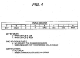
- Fig. 4 is a view showing the configuration of a status register provided in the drive 10.
- This status register is one of ATA registers and an 8-bit register.
- the host device 40 can read bits from this status register; ascertains the current status of the drive 10 by means of the thus-read bits; and controls transfer of data to the buffer 24 on the basis of the thus-ascertained current status. Details of the status register are as shown in Fig. 4.
- the BSY (busy) bit, a DRQ (data request) bit, and an ERR (error) bit are especially utilized. Specifically, in order to suspend transmission of data from the host device 40, the BSY bit is utilized, and occurrence of "buffer under run" is reported to the host device 40 by use of the ERR bit.
- Fig. 5 is a status transition chart for describing operation of the host device 40.
- the host device 40 reads bits from the status register provided in the drive 10 (52).
- the host device waits until all the bits assume a value of 0.
- the WRITE command is issued to the drive 10 (53), and the bits are read from the status register (54). Consequently, when the BSY bit assumes a value of 1, the host device waits until the BSY bit assumes a value of 0, and the DRQ bit assumes a value of 1.
- Fig. 6 is a status transition chart for describing operation of the drive 10.
- the drive 10 clears the error flag (referred error flag) provided in the drive 10 (62).
- the drive 10 then resets all the BSY, DRQ, and ERR bits of the status register to zero (63), and awaits a command from the host device 40 (64).
- the drive 10 sets the BSY bit in the status register to a value of 1 (65), and checks the error flag (66).
- the error flag is not set, the BSY bit of the status register is set to a value of 0, and the DRQ bit of the same is set to a value of "1" (67).
- the drive 10 then awaits receipt of rendering data from the host device 40 (68). Upon receipt of rendering data from the host device 40 (69), the drive 10 transfer the received data to the buffer 24 (70). When receipt of the rendering data has been completed, a rendering status is ascertained (71). When the rendering status is not achieved, the status of the buffer 24 is ascertained (72). Since the buffer 24 is first not FULL, the BSY bit is set to a value of 0 (73), and the drive 10 returns to the command await status (69). Upon receiving the WRITE command again, the drive 10 iterates the previously-described operations. When the buffer status has become FULL, rendering of a visible image to the optical disk 1 is started (74).
- the data stored in the buffer 24 are sequentially read, and the thus-read data are supplied to the encoder 25. Encoding is commenced. As mentioned above, the BSY bit is set to a value of 0 (73), and the drive 10 returns to awaiting the command (64).
- the drive 10 Upon receipt of the WRITE command, the drive 10 operates in the same manner as mentioned previously. Since rendering has already been started by this time, rendering is understood to be in process by means of the rendering status ascertainment (71), and the status of the buffer 24 is ascertained (75). Even when an ordinary status where the volume of data is equal to or less than the "buffer under run” threshold value is achieved despite of the BSY bit being set to "0,” the drive 10 returns to a status of awaiting a command (64) as in the previous case (73). When the buffer is FULL, the drive 10 waits until the buffer goes out of the FULL status as a result of data being read by the encoder 25.
- the error flag is set (76); the BSY bit is set to "0" (73); and the drive 10 returns to a status of awaiting a command.
- the error flag becomes set by means of an error flag check (66), whereupon the BSY bit of the status register is set to "0,” and the ERR bit of the same is set to "1" (77).
- the drive 10 interrupts writing of data, to thus perform error processing (78) and return to the status after commencement.
- the host device 40 can ascertain the status of the status register by means of setting the ERR bit of the status register to "1.” As described in connection with Fig. 5, the host device 40 performs error processing when the ERR bit is 1. In this illustrated case, when the volume of data in the buffer has become equal to or less than the "buffer under run” threshold value, the ERR bit is set to 1. Accordingly, the host device 40 waits until the drive 10 recovers from the error status, without discarding data. When the drive 10 has recovered from the error status, transfer of subsequent data is commenced. As mentioned above, when "buffer under run” occurs or when occurrence of "buffer under run” is predicted, rendering of a visible image can be spliced in a visually-smooth manner.
- the S' pulse is a signal which is determined by means of subjecting the FG pulse to frequency division at an appropriate frequency dividing ratio and shows the accurate rotational position of the spindle. This signal is further subjected to frequency division, to thus generate an S" pulse signal which generates one pulse every rotation of the spindle. So long as the S" pulse is subj ected to frequency multiplication by means of a PLL circuit or the like, a signal representing a larger number of accurate rotational positions of the spindle can be generated. By use of this signal, there can be obtained a larger number of positions per revolution where rendering can be started.
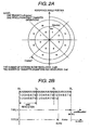
- rendering operation can be caused to pause and resume on a per-transfer-unit basis by means of subjecting the S" pulse to X multiplication by use of X, which is the number of transfer operations per revolution. More specifically, rendering operation can be caused to pause and resume at eight positions during one revolution, so long as the embodiment shown in Fig. 2A is employed.
- the pause and resumption of rendering operation can be controlled at a unit which is finer than the transfer unit. Therefore, interruption of rendering, which will be induced by a cause other than a transfer rate such as disturbance, can also be sufficiently addressed.
Landscapes
- Engineering & Computer Science (AREA)
- Multimedia (AREA)
- Signal Processing (AREA)
- Optical Recording Or Reproduction (AREA)
- Signal Processing For Digital Recording And Reproducing (AREA)
Abstract
Description
- The present invention relates to an optical disk recording system which forms a visible image on a disk surface of an optical disk, such as a CR-R/RW, a DVD+R/RW, or a DVD-R/RW, by use of a laser.
- Recording a visible image, such as characters or graphics, on a recording surface of an optical disk or a label surface (a surface opposite the recording surface) of the same by use of a laser has been known.
For instance,Patent Document 1 proposes a technique of providing a visible light characteristic changing layer at a position which is viewable from a label surface side of an optical disk; and exposing the visible light characteristic changing layer to a laser beam to thus change a visible light characteristic of the layer and render a visible image.
Patent Document 2 proposes a technique of using a reversible phase change material for a recording film of an optical disk, which enables recording of a visible image by use of a laser, and rewriting recorded graphics.
Patent Document 3 proposes a technique of newly writing a visible image on a recording surface of an optical disk on which a visible image has already been recorded. -
Patent Document 4 proposes a visible image recorder capable of preventing occurrence of a failure of adj acent pixels in a visible image to be recorded at separated positions to thus record a visible image, differing from the original image, which would otherwise be caused when the visible image has been brought out of focus by a servo during recording of a visible image.
Patent Document 4 also describes, as a way to determine an angle position θ, a technique of determining a single rotation from a predetermined number of cycles; generating a pulse signal every predetermined number of cycles; and determining an angle position by means of the number of pulses (Fig. 6).
Patent Document 1:JP-A-2002-203321
Patent Document 2:JP-A-2003-016649
Patent Document 3:JP-A-2004-039019
Patent Document 4:JP-A-2004-030832 - The invention described in
Patent Document 4 describes out-of-focus but provides no description about "buffer under run."
"Buffer under run" is an interruption of recording which can arise irrespective of focus control. An interruption of recording attributable to out-of-focus and an interruption of recording attributable to "buffer under run" are totally different from each other in terms of the amount of data which remain in a buffer of an optical disk drive unit at the time of occurrence of the interruption. As above, "buffer under run" is a phenomenon which cannot be predicted fromout-of-focus, and hence out-of-focus and "buffer under run" cannot be discussed in the same terms. - Accordingly, the present invention aims at providing an optical disk recording system which enables visually-smooth rendering even when rendering has been interrupted as a result of occurrence of "buffer under run" or when occurrence of "buffer under run" is predicted.
In order to achieve the above object, the present invention is characterized by having the following arrangements. - (1) An optical disk recording system comprising:
- an optical disk;
- an optical disk drive unit that includes buffer storage means for temporarily storing data to be transferred from a host device, and rotating means for holding and rotating the optical disk and outputting an angle position signal, the optical disk drive unit recording on the optical disk a visible image corresponding to the data; and
- the host device that is provided for transferring the data to the optical disk drive unit,
- wherein the optical disk drive unit interrupts recording operation when an error of data emptiness in the buffer storage means occurs in the course of recording during a predetermined revolution of the optical disk,
- the host device resumes transfer of data after discarding data corresponding to a section between a position where the error occurs and the reference angle position on the optical disk, and
- the optical disk drive unit resumes receipt of data, to resume recording operation from the reference angle position.
- (2) An optical disk recording system comprising:
- an optical disk;
- optical disk drive unit that includes,
buffer storage means for temporarily storing data to be transferred from a host device,
rotating means for holding and rotating the optical disk and outputting an angle position signal,
signal processing means for reading, from the buffer storage means, data corresponding to a predetermined number of sectors during one revolution of the optical disk and for processing the read data, and
light-emitting means for emitting a laser beam at power responsive to the data processed by the signal - processing means to record the data on the optical disk; and
- the host device that transfers the data to the optical disk drive unit, and includes count means for counting the number of sectors of the data transferred to the optical disk drive unit,
- wherein the optical disk drive unit temporarily interrupts receipt of data from the host device when an error of data emptiness in the buffer storage means occurs in the course of recording during a predetermined revolution of the optical disk, and sends a report to the effect to the host device and interrupts recording of data to the optical disk,
- wherein the host device specifies data corresponding to a section between a position where the error occurs and a start position of the next revolution, based on the number of sectors counted by the count means when the error of data emptiness occurs in the optical disk drive unit and the predetermined number of the sectors, and resumes transfer of data after discarding the specified data, and
- wherein the optical disk drive unit resumes receipt of data to resume recording operation from the start position of the next revolution.
- (3) An optical disk recording system comprising:
- an optical disk;
- an optical disk drive unit that includes
buffer storage means for temporarily storing data to be transferred from a host device,
rotating means for holding and rotating the optical disk and outputting an angle position signal,
signal processing means for reading, from the buffer storage means, data corresponding to M×N sectors (N, M denotes natural numbers) during one revolution of the optical disk and processes the read data, and
light-emitting means for emitting a laser beam at power responsive to the data processed by the signal processing means to record data on the optical disk; and - the host device transfers to the optical disk drive unit the data corresponding to N sectors by one transfer operation, and includes count means for counting the number of operations for transferring data to the optical disk drive unit,
- wherein the optical disk drive unit temporarily interrupts receipt of data from the host device when an error of data emptiness in the buffer storage means occurs in the course of recording during a predetermined revolution of the optical disk, and sends a report to the effect to the host device and interrupts recording of data to the optical disk,
- wherein the host device specifies the data corresponding to a section between a position where the error occurs and a start position of the next revolution, based on the number of transfer operations counted by the count means when the error of data emptiness occurs in the optical disk drive unit and the number M, and resumes transfer of data after discarding the specified data, and
- wherein the optical disk drive unit resumes receipt of data, to resume recording operation from the start of the next revolution.
- (4) An optical disk recording system comprising:
- an optical disk;
- an optical disk drive unit that includes
buffer storage means for temporarily storing data to be transferred from a host device,
rotating means for holding and rotates the optical disk and outputting an angle position signal,
signal processing means for reading, from the buffer storage means, data corresponding to a predetermined number of sectors during one revolution of the optical disk and processing the read data,
light-emitting means for emitting a laser beam at power responsive to the data processed by the signal processing means to record data on the optical disk, and
monitoring means for predicting occurrence of an error of data emptiness stored in the buffer storage means; and - the host device for transferring the data to the optical disk drive unit,
- wherein, during the course of recording for a predetermined revolution of the optical disk, the optical disk drive unit reports an anomaly to the host device when the monitoring means predicts occurrence of an error of data emptiness in the buffer storage means; temporarily interrupts receipt of the data from the host device; interrupts recording of the data on the optical disk after occurrence of an error of data emptiness in the buffer storage means; subsequently resumes receipt of data from the host device; and resumes recording operation from a start position of the next revolution.
- (5) The optical disk recording system according to (4), wherein the monitoring means includes detection means for detecting a volume of data stored in the buffer storage means and a volume of data output from the buffer storage means, and predicts occurrence of an error of data emptiness in the buffer storage means based on the volume of stored data, the volume of output data, and the predetermined number of the sectors.
- (6) The optical disk recording system according to (5), wherein, when a remainder obtained by dividing a total sum of the volume of stored data and the volume of output data by the predetermined number is zero and the volume of stored data is equal to or less than the volume of data corresponding to the predetermined number of sectors, the monitoring means predicts occurrence of an error of data emptiness in the buffer storage means.
- (7) An optical disk recording system comprising:
- an optical disk;
- an optical disk drive unit that includes
buffer storage means that temporarily stores data to be transferred from a host device,
rotating means holding and rotating the optical disk and outputting M (M denotes a natural number) angle position signals per revolution,
signal processing means for reading, from the buffer storage means, data corresponding to MxN sectors (N denotes a natural number) during one revolution of the optical disk and processes the read data, and
light-emitting means for emitting a laser beam at power responsive to the data processed by the signal processing means, to record the data on the optical disk; and - the host device that transfers the data to the optical disk drive unit, and includes count means for counting the number of sectors of data transferred to the optical disk drive unit,
- wherein the optical disk drive unit temporarily interrupts receipt of data from the host device when an error of data emptiness in the buffer storage means occurs in the course of recording during a predetermined revolution of the optical disk, and sends a report to the effect to the host device and interrupts recording of the data to the optical disk,
- wherein the host device specifies the data corresponding to a section between a position where the error occurs and a position specified by the angle position signal, based on the number N and the number of sectors counted by the count means when the error of depletion of data occurs in the optical disk drive unit, and resumes transfer of the data after discarding the specified data, and wherein the optical disk drive unit resumes receipt of data to resume recording operation according to the angle position signal.
- (8) An optical disk recording system comprising:
- an optical disk;
- an optical disk drive unit that includes
buffer storage means for temporarily storing data to be transferred from a host device,
rotating means for holding and rotating the optical disk and outputting N×M (N, M denote natural numbers) angle position signals per revolution,
signal processing means for reading, from the buffer storage means, data corresponding to NxM sectors during one revolution of the optical disk and processing the read data, and
light-emitting means for emitting a laser beam at power responsive to the data processed by the signal processing means to record data on the optical disk; and - the host device that transfers the data to the optical disk drive unit, and includes count means that counts the number of sectors of the data transferred to the optical disk drive unit,
- wherein the optical disk drive unit temporarily interrupts receipt of data from the host device when an error of data emptiness in the buffer storage means occurs in the course of recording during a predetermined revolution of the optical disk, and sends a report to the effect to the host device and interrupts recording of data to the optical disk,
- wherein the host device specifies data corresponding to a duration between a location where an error occurs and the angle position signal, from the number of sectors counted by the count means when the error of data emptiness occurs in the optical disk drive, and resumes transfer of data after having discarded the specified data, and
- wherein the optical disk drive unit resumes receipt of data, to thus resume recording operation from the start of the next revolution in accordance with the angle position signal.
- (9) A method of controlling an optical disk recording system that comprises an optical disk drive including buffer storage means for temporarily storing data to be transferred from a host device and rotating means for holding and rotating an optical disk and outputting an angle position signal, the optical disk drive unit recording on an optical disk a visible image based on data, and the host device for transmitting the data to the optical disk drive unit, the method comprising:
- transferring the data from the host device to the optical disk drive unit;
- interrupting recording operation by the optical disk drive unit when an error of data emptiness in the buffer storage means occurs in the course of recording during a predetermined revolution of the optical disk;
- resuming transfer of data by the host device after discarding data corresponding to a section between a position where the error occurs and the reference angle position on the optical disk; and
- resuming receipt of data by the optical disk drive unit, to resume recording operation from the reference angle position.
- (10) An optical disk drive unit for receiving data transferred from a host device and recording on an optical disk a visible image corresponding to the data, the optical disk drive unit comprising:
- buffer storage means for temporarily storing data to be transferred from the host device;
- rotating means for holding and rotating the optical disk and outputting an angle position signal,
- wherein recording operation is interrupted when an error of data emptiness in the buffer storage means occurs in the course of recording during a predetermined revolution of the optical disk, and
- wherein the buffer storage means resumes storing data, transferred from the host device, in which data corresponding to a section between a position where the error occurs and the reference angle position on the optical disk is discarded, to resume recording operation from the reference angle position.
- According to such an optical recording system of the present invention, evenwhen rendering is interrupted as a result of "buffer under run" having arisen because of delayed transfer of image data from host device or even when occurrence of "buffer under run" error is predicted, an angle on a disk where an interruption has arisen is computed, and the host device resumes rendering by means of transferring spliceable rendering data in consideration of the thus-computed angle, to thus make an accurate rendering splice.
Even when the processing speed of the host device is not sufficient, visually-smooth rendering is enabled. -
- Fig. 1 is a block diagram showing the configuration of a principal portion of an embodiment of an optical disk recording system according to the present invention;
- Figs. 2A and 2B are views for describing processing performed in the event of occurrence of "buffer under run";
- Figs. 3A to 3H are views for describing operation of a
buffer 24; - Fig. 4 is a view showing the configuration of a status register provided in a
drive 10; - Fig. 5 is a status transition view for describing operation of
host device 40; and - Fig. 6 is a status transition view for describing operation of the
drive 10. - Fig. 1 is a block diagram showing the principal configuration of an embodiment of an optical disk recording system of the present invention.
The optical disk recording system of the present embodiment comprises an opticaldisk drive unit 10 which records and reproduces data to and from anoptical disk 1 and forms a visible image; andhost device 40, such as a host computer, a backend device, or the like, connected to the opticaldisk drive unit 10. Thehost device 40 is equipped with an image editing program for editing a visible image to be recorded on theoptical disk 1, and a control program for recording data and a visible image on theoptical disk 1 and reproducing data from theoptical disk 1.Reference numeral 41 designates buffer memory for temporarily storing data to be transferred from thehost device 40 to the opticaldisk drive unit 10. Thehost device 40 sequentially reads the data stored in thebuffer memory 41 and transfers the thus-read data to buffermemory 24 of the opticaldisk drive unit 10. The function of thehost device 40 may be imparted to the opticaldisk drive unit 10. - The optical
disk drive unit 10 comprises aspindle motor 11 for rotationally driving theoptical disk 1; afrequency generator 12 for outputting an FGpulse of a frequency responsive to the rotational speed of the spindle; anoptical pickup 13; anRF amplifier 14; aservo circuit 15; adecoder 16; anaddress detection circuit 17; acontrol portion 18; a steppingmotor 19; amotor driver 20; amotor controller 21; afrequency divider circuit 22; an LPC (Laser Power Control)circuit 23 for controlling laser power; thebuffer memory 24; anencoder 25; astrategy circuit 26; alaser driver 27 for driving a laser diode of theoptical pickup 13; ademodulator circuit 28 and an ANDcircuit 29 which are used for recording a visible image; and aninterface circuit 30 for exchanging data among thecontrol portion 18, thebuffer memory 24, and thehost device 40. - The
optical pickup 13 radiates a laser beam onto theoptical disk 1 to thus record and reproduce data as well as to render a visible image. A returned-light reception signal (an RF signal having undergone EFM modulation or 8-to-16 modulation), which is generated upon receipt of the light returned at the time of the laser beam having been radiated onto the optical disk l, is amplified by theRF amplifier 14. The thus-amplified signal is supplied to theservo circuit 15, thedecoder 16, and theaddress detection circuit 17.
On the basis of the signal output from theRF amplifier 14 and the control signal output from thecontrol portion 18, theservo circuit 15 controls the rotation of thespindle motor 11 and controls the focus and tracking of theoptical pickup 13.
Thedecoder 16 demodulates the signal that is supplied from theRF amplifier 14 and has undergone EFM modulation or 8-to-16 modulation, and outputs reproduced data.
Theaddress detection circuit 17 extracts a wobble signal component from the signal supplied from theRF amplifier 14; demodulates an ADIP (Address In Pre-Groove) of DVD-based specifications or an ATIP (Absolute Time in Pre-Groove) of CD-based specifications; and detects address information (a positional address). - The stepping
motor 19 is a motor for actuating (feeding) theoptical pickup 13 in a radial direction of theoptical disk 1. Themotor driver 20 rotationally drives the steppingmotor 19 in accordance with the control signal supplied from themotor controller 21. Pursuant to an actuation start command, including the actuating direction and the distance of actuation of theoptical pickup 13 in the radial direction, issued by thecontrol portion 18, themotor controller 21 generates a pulse signal responsive to the distance of actuation and the actuating direction, and supplies the thus-generated signal to themotor driver 20. - The
buffer memory 24 is buffer memory, which is formed from FIFO (First In First Out) memory, for recording data (recording data)―which are supplied from thehost device 40 by way of theinterface circuit 30 and are to be recorded onto theoptical disk 1―and data pertaining to a visible image to be rendered on the optical disk.
When the recording data are recorded on theoptical disk 1, theencoder 25 subjects the recording data read from thebuffer memory 24 to EFM modulation or 8-to-16 modulation; and outputs the thus-modulated data to thestrategy circuit 26. Thestrategy circuit 26 subjects the signal supplied from theencoder 25 to time-axis correction processing, or the like; and outputs the thus-processed signal to thelaser driver 27. Thelaser driver 27 drives the laser diode of theoptical pickup 13 in accordance with the modulated signal supplied from thestrategy circuit 26 and control of theLPC circuit 23. - Operation performed when a visible image is recorded on the
optical disk 1 and operation performed at the time of occurrence of "buffer under run" will now be described in detail. - An image or characters are rendered on a data recording surface or a label surface of the
optical disk 1 loaded in the optical disk drive unit (hereinafter simply called a "drive") 10 while data are being transferred from the host device (a computer, a back-end device, or the like) 40 to thedrive 10.
At this time, thespindle motor 11 of thedrive 10 is rotated at a given rotational velocity (CAV: Constant Angular Velocity), and a focus actuator servos the recording surface or the label surface in the same manner as does a focus servo system of an ordinary optical disk. The tracking actuator is made free without being servoed, or a periodic (a sinusoidal wave, a triangular wave, or the like) electric current is caused to flow into the tracking actuator, thereby swinging the actuator. Feeding is gradually performed from an inner radius to an outer radius, or vice versa.
RAW mode encoding operation of an ordinary CD-R/RW is taken for encoding operation to be performed in thedrive 10. However, encoding of a TAO (track at once) mode is also allowable. In relation to the laser, as in the case of ordinary CD-R/RW recording operation, the power of the laser is switched between high and low by means of a pulse signal originating from an EFM signal generated by the encoder (CD encoder) 25. Write power required herein is higher than or equal to a certain power level at which visual traces are left on the recording surface or the label surface of theoptical disk 1. By means of this power, a doughnut-shaped trace can be left on theoptical disk 1. - As illustrated, the
demodulator 28 for detecting a certain EFM pattern is provided in a stage subsequent to theencoder 25 of thedrive 10. Thedemodulator 28 is set so as to output a HIGH value upon detection of a certain specific EFM pattern and output a LOW value at other times. The ANDcircuit 29 subjects to AND operation an output from thedemodulator 28 and the pulse signal to be input to the laser, and delivers an AND result to thelaser driver 27.
As a result, a laser beam of write power and a laser beam of read power are alternately emitted only in a certain specific EFMpattern, in accordance with the EFM signal, whereby recording traces are left on theoptical disk 1. At other EFM patterns, a laser beam of read power is always emitted, and no recording traces are left on theoptical disk 1. The EFM pattern is originally generated from the data transferred from thehost device 40. Hence, a visible image, such as images or characters, can be rendered on theoptical disk 1 by means of transmitting, from thehost device 40, data corresponding to images or characters to be rendered. - In order to realize a smooth rendering splice after occurrence of "buffer under run," the angle position of the spindle must be detected. In order to detect the angle position of the spindle, the
frequency generator 12, which employs counter electromotive force of a hall sensor or a spindle coil, is used. In the present embodiment, thefrequency generator 12 is arranged to generate pulses of exactly S cycles (FG pulses) per rotation of the spindle motor (S: an integer, S>0). Consequently, a pulse duration of each of the pulses of S cycles assumes the following value.
frequency divider circuit 22 subj ects the FG pulses generated by thefrequency generator 12 to frequency division at an appropriate frequency division ratio by means of hardware or software, so that a highly-accurate pulse of an S' cycle per revolution can be obtained (S': an integer, S'>0). An appropriate frequency division ratio varies in accordance with the type or structure of a motor. However, there usually exists a frequency division ratio at which an accurate pulse of one cycle can be generated at least in one revolution.
Under another angle position detection method, an obj ect subject to detection, which is printed directly on theoptical disk 1 or attached to the same, is detected by use of a detection element, to thus enable detection of an accurate angle position. - One radial direction is previously set on the
optical disk 1 as a reference angle position thereof. A predetermined mark, which is used for representing the reference angle position, is provided on the front surface or reflection layer of theoptical disk 1. The predetermined mark is a sub-code or header showing a specific time position, an ATIP or ADIP showing a specific address, a barcode or another mark formed by means of visible image formation processing on or printed on the front surface or reflection layer of an optical disk, or any mark which can be read by use of optical means such as theoptical pickup 13.
Thecontrol portion 18 of thedrive 10 detects a mark, which shows the reference angle position, from an output from theaddress detection circuit 17 or an output from thedecoder 16, to thus acquire a count of a pulse signal (S' pulse) generated at S' cycles per revolution at a point in time when the mark has been detected; and saves the thus-acquired count. When the count of the S' pulse has become equal to the saved count, theoptical pickup 13 is understood to remain in contact with the reference angle position on the optical disk.
When the disk is first subj ected to rendering or rendering splicing (a visible image is written once), rendering is initiated in synchronism with this reference angle position. Thereby, rendering and recording can be started every time from the same angle position (the reference angle position) on the disk, regardless of the number of times rendering is performed. - A WRITE command, or the like, of ATAPI (AT Attachment Packet Interface) is used for transfer of data from the
host device 40 to thedrive 10. Encoding of data performed in thedrive 10 will be described hereunder as RAW mode encoding of a common CD-R/RW. However, encoding of data may also be performed in a TAO mode without involving a problem. In the case of the RAW mode, the number of bytes of one sector of data transferred from thehost device 40 to thedrive 10 is 2448 bytes. 98 EFM frames are present in one sector, and 24 bytes of main data are present in one EFM frame. Further, 96 bytes of sub-codes are present in one sector. Therefore, we have
In the case of the TAO mode, the 96 bytes of sub-codes are unnecessary, and hence we have 2352 bytes.
The unit at which data are transferred in accordance with the WRITE command, or the like, corresponds to several sectors. Provided that the number of sectors required for one transfer of data is taken as N and the number of bytes required for one transfer of data is taken as M, M is defined as
- An encode frequency (an n-fold CD encoding speed) (hereinafter called an "n× CD encoding speed") and a spindle rotational velocity, by means of which data exactly corresponding to an integral number of data transfer operations are encoded during one revolution of the disk, are set in advance for the
drive 10.
For instance, in an example case where rendering is performed over a revolution of an optical disk when a single transfer of data corresponding to 15 sectors has been performed exactly six times, - n× encoding speed of the drive 10: 45x speed of a CD, and
- the rotational velocity of the spindle: 2250 rpm are set. The reason for this is as follows:
- Encoding operation of the CD encoder is set so as to process 75 sectors per second at a standard speed (called 1× speed). When the rotational speed is converted into the number of bytes, data are processed at a rate of

per second. On the assumption that data are encoded at 45x speed, the number of bytes processed per second is 45 times the solution of Equation (6-1), and hence we have
- In contrast, transfer of data from the
host device 40 during a single revolution of the disk is achieved when transfer of data corresponding to 15 sectors has been performed six times. Hence, the number of bytes for one revolution of disk is determined as
- From Equations (6-2) and (6-3), we have

In other words, we have the following rotational velocity:
- As above, when trans fer of data corresponding to 15 sectors is performed six times per revolution of the disk, 45x CD encoding speed and a rotational velocity of 2250 [rpm] for the spindle are understood to be an example setting for firmware. Now, attention must be paid to the requirement that all the numerals provided above must be combinations of numerals which can be implemented by hardware. For instance, when the nx CD transfer speed is set so as to assume an irrational number, implementing the setting is nearly impossible, in view of hardware.
Given that the number of times data are required to be transferred from thehost device 40 in order to record data corresponding to a revolution of the disk is taken as X, the number of sectors L per revolution of the disk is determined as
- Encoding (rendering and recording) is commenced from the reference angle position on the disk. Specifically, when the number of counts of the S' pulse has become equal to the count of the S' pulse that has beenmeasured and saved in "4. Detection of the reference angleposition" and corresponds to the reference angle position on the optical disk, the
encoder 25 is caused to initiate encoding of the image data for that revolution. Use of this method enables commencement of rendering and recording from the same angle position (the reference angle position) on the disk every time, regardless of the number of times rendering is performed.
In the present invention, thehost device 40 is provided with a sector counter. This counter increments by one every time data corresponding to one sector are transferred to thedrive 10 on condition that the sector, from which rendering or re-rendering is commenced, is taken as 0. The count of this counter is taken as T. - When the optical disk on which a visible image is recorded is taken out of the drive and the disk is not again inserted into the drive and recorded; namely, when a visible image is recorded only once on the optical disk, the reference angle position on the optical disk, which has been detected as mentioned above, does not need to be used. In this case, the essential requirement is to start encoding at a timing corresponding to the reference angle position by means of taking a position, at which an FG pulse or the S' pulse output from the
frequency generator 12 in "3. Spindle motor" arises, as a reference angle position without detecting the reference angle position mentioned in connection with "4. Detection of the reference angle position." - When the speed at which data are transferred from the
host device 40 is slower than the speed at which data are written from thedrive 10 to the optical disk 1 (i.e., the encoding speed), or when, for some reason, transfer of data from thehost device 40 to thedrive 10 is interrupted for at least a certain period of time, data in thebuffer memory 24, which are to be written into theoptical disk 1, become depleted, whereupon rendering and recording operations are interrupted. This phenomenon is called "buffer under run." In the present invention, when "buffer under run" occurs during recording of a visible image or when occurrence of "buffer under run" is predicted, rendering can be made visually smooth as follows: - When rendering is interrupted as a result of occurrence of "buffer under run," the
drive 10 suspends feeding action at that position where rendering has been interrupted or records the feed position in memory and actuates theoptical pickup 13 to that position when rendering is spliced. Further, the spindle is left rotating while the rotational speed of the spindle is maintained.
When rendering has been interrupted, thehost device 40 divides the T sectors (the number of transferred sectors) by the L sectors (the number of sectors in one revolution of a disk), to thus determine a remainder Z.
where mod{x/y} represents a remainder obtained when "x" is divided by "y." - Descriptions are hereinbelow provided for the case where the remainder Z is zero and for the case where the remainder z is not zero.
- In this case, rendering has been interrupted immediately before the reference angle position. Consequently, rendering can be spliced from the reference angle position without interruption, so long as the
host device 40 transfers the data without modifications to thedrive 10 to thus resume rendering. Simultaneously with resumption of rendering, feeding is also performed from the inner radius to the outer radius, or vice versa. - In this case, the remainder Z represents the number of sectors excessively rendered with respect to the reference angle position. Consequently, the number of sectors R, which are deficient in recording before the reference angle position, is obtained as follows:

Thehost device 40 discards data corresponding to the head R sector of the next data to be transferred from thebuffer 41, and transfers to thedrive 10 data subsequent to the thus-discarded data. By means of this, when thedrive 10 has again resumed rendering, only a portion of data is lost, but rendering of a graphical pattern can be spliced without interruption from the reference angle position.
Simultaneously with resumption of rendering, feeding is also gradually performed from the inner radius to the outer radius, or the vice versa.
There is a concern of rendering becoming thin by the amount corresponding to the data discarded by thehost device 40. However, in reality, rendering becomes thin to such an extent that thinning is not visually discerned. - In light of 9-1 and 9-2, operations are generalized as follows. When "buffer under run" occurs, the
host device 40 determines the number of sectors R which are deficient in recording before the reference angle position. Next, data corresponding to the head R sector of the next data to be transferred are discarded (data are not discarded in the case of R=0), and data subsequent to the discarded data are transferred to thedrive 10. - Although the number of all sectors has been handled as units in 9, the same advantage is yielded even when the number of transferring operations is computed. The
host device 40 is provided with a transfer operation counter which increments by one every time data are transferred from thebuffer 41 to thedrive 10, and a count value of the counter is taken as D. when rendering has been interrupted by "buffer under run," thehost device 40 divides the number of transferring operations D (the total number of transfer operations) by X (the number of transfer operations performed per one revolution of the disk), to thus determine a remainder Q.
The number of transfer operations V, which are deficient in recording before the reference angle position, is determined as
Therefore, when "buffer under run" occurs, thehost device 40 determines V; discards data, which will be transferred through operations which are data of V times transfer from the head sector of the next data to be transferred from the buffer 41 (the data are not discarded in the case where V=0) ; and transfers to thedrive 10 data subsequent to the thus-discarded data. - Specific descriptions will be provided by reference to Figs. 2A and 2B.
As shown in Fig. 2A, this embodiment shows a case where data corresponding to N sectors are transferred from thehost device 40 to the drive 10 per data transfer operation, and where data which is equal in quantity to one revolution are transferred by means of eight data transfer operations. At this time, the number of sectors L of one revolution is L=8N, and the number of transfer operations for one resolution is X=8.
"Type A" in Fig. 2B shows a case where recording is interrupted as a result of occurrence of first "buffer under run" (BUR1) when transfer of data―being equal in quantity to three revolutions―has just been completed.
At this time,
a total number of transfer operations: D=3×X=24, and
the number of remainder transfer operations:
is obtained. Discarding of data is not performed in thehost device 40, and recording is continued from the reference angle position while the feeding position is being retained. In this case, there is no splice.
"Type B" in Fig. 2B shows a case where recording is interrupted as a result of occurrence of second "buffer under run" (BUR2) when data which is equal in quantity to two revolutions and two transfer operations have been transferred.
At this time,
a total number of transfer operations: D=2X+2=18,
the number of remainder transfer operations:
and
the number of discarded transfer operations: V=x-Q=8-2=6 are obtained.
Consequently, thehost device 40 discards data, which will be transferred by six transfer operations, while the feeding position is being maintained, and resumes recording from the reference angle position. - The methods, which have been described thus far, involve discarding of data which are not visually discernible. In order to avoid discarding of data, rendering can be spliced without discarding data by use of a method described below.
Thedriver 10 is provided in advance with a sector counter for counting the number of sectors transferred from thebuffer 24 to the optical disk 1 (i.e., the encoded sectors). This counter takes a sector, at which rendering or re-rendering is started, as zero and increments by one every time one sector is transferred to theoptical disk 1. A count value of this counter is taken as B. When the WRITE command has been issued by thehost device 40 and when the volume of data remaining in thebuffer 24 is a "threshold value of buffer under run," a "buffer under run" error is returned. As in the case of foregoing 9, the "thresholdvalue of buffer under run" is derived as follows:
The threshold value must be determined every time B is incremented. - As a result, when the
host device 40 has requested data transfer by means of the WRITE command, thedriver 10 returns a "buffer under run" error, to thus prevent receipt of rendering data from thehost device 40. Thereupon, thehost device 40 detects the "buffer under run" error of thedrive 10 to thereby suspend transfer of data. Subsequently, at the time of re-start of rendering, thehost device 40 transmits data from the reference angle position. Further, thedrive 10 also starts rendering from the reference angle position. Accordingly, rendering can be spliced without discarding data. - By a combination of 10 and 11, rendering can also be spliced by means of calculating the number of transfer operations without discarding data.
Thedrive 10 is provided beforehand with a counter for counting the number of times data are transferred from thehost device 40. A count value of this counter is taken as Y. In this case, the "threshold value of buffer under run" is obtained as follows:
"Threshold value of buffer under run"=X-mod{Y/X}
This must be determined every time Y is incremented.
This method is based on the premise that "buffer under run" does not occur during transfer of rendering data. Since "buffer under run" usually occurs when a time duration between one transfer operation and the next transfer operation becomes longer, this method does not pose any substantial problem. - The "threshold value of buffer under run" is described in detail by reference to Figs. 3A to 3H.
The buffer (FIFO) 24 provided in thedrive 10 is assumed to be represented as Fig. 3A.
In this drawing, data flow from up to down. Further, the quantity of data transferred in one operation is assumed to correspond to the volume of data shown in Fig. 3B. As shown in Fig. 3C, thebuffer 24 can retain exactly the volume of data which will be transferred by eight operations.
Fig. 3D shows that thebuffer 24 is EMPTY.
Fig. 3E shows that thebuffer 24 is FULL.
The data transferred from thehost device 40 are input to the buffer from above in the drawing. Data used for rendering are output to thedisk 1 from below in the drawing, and the thus-output data are input to theencoder 25.
Usually, the data that have been received at the beginning are not output from thebuffer 24. Therefore, data are stored in thebuffer 24 as a result of the data being transferred from and input by thehost device 40. When the buffer has become FULL, the data are output from thebuffer 24 for the first time, and recording of data on theoptical disk 1 is started.
During ordinary recording operation, recording is performed while the volume of data remaining in the buffer varies between 1 and 8.
when thebuffer 24 has become EMPTY, recording is interrupted by the "buffer under run" error.
When thebuffer 24 has become FULL, a BSY bit of a status register, which will be described later, is left as "1," thereby suspending receipt of data from thehost device 40. When a space, which corresponds to the volume of data transferred in one operation, is generated in thebuffer 24, BSY is assigned 0, thereby receiving data from thehost device 40. - For instance, the number of data transfer operations required for one revolution of the disk is assumed to be three.
Thedrive 10 has a counter for counting the number of times data are transferred from thebuffer 24 to theoptical disk 1. By means of a remainder obtained by dividing the count value by three, the threshold value of buffer under run is sequentially changed as follows:
When a remainder, which is obtained by means of dividing by three the number of times data are transferred from the buffer to the disk, is zero, the threshold value of buffer under run=the volume of data corresponding to three transfer operations (Figs. 3F). When the remainder is one, the threshold value of buffer under run=the volume of data corresponding to two transfer operations (Figs. 3G). When the remainder is two, the threshold value of buffer under run=the volume of data corresponding to one transfer operations (Figs. 3H).
A remainder, which is obtained by means of dividing by three the number of times data are transferred from the buffer to the disk, represents the data rendered on the disk after the reference angle position. Therefore, the threshold value of "buffer under run" is determined such that the rendered data become equal in volume to one revolution of the disk in conjunction with the data still remaining in the buffer.
As in the case of 12, thedrive 10 may be provided with a counter for counting the number of times Y data are transferred from thehost device 40. A value, which is determined by subtracting from X a remainder―being obtained by dividing the count value Y by the number of data transfer operations X in one revolution―may be taken as the threshold value of "buffer under run." - Thus, when the
host device 40 attempts to transfer data in the states shown in Figs. 3F, 3G, and 3H, thedrive 10 returns the "buffer under run" error, to thus halt receipt of data. Upon receipt of the error fromdrive 10, thehost device 40 suspends transmission of data (temporary suspension). Subsequently, the data still remaining in the buffer are sequentially recorded on the disk, and the buffer becomes empty, whereupon recording is interrupted.
As a result, when "buffer under run" occurs, recording is suspended, at all times, at a position immediately before the reference angle position on the disk.
Just as mentioned previously, thedrive 10 receives the next data intact, and starts writing the data onto the disk when the buffer has become FULL. Since writing of data is started from the reference angle position at all times, rendering can be spliced smoothly without discarding data. - Fig. 4 is a view showing the configuration of a status register provided in the
drive 10. This status register is one of ATA registers and an 8-bit register.
Thehost device 40 can read bits from this status register; ascertains the current status of thedrive 10 by means of the thus-read bits; and controls transfer of data to thebuffer 24 on the basis of the thus-ascertained current status.
Details of the status register are as shown in Fig. 4. The BSY (busy) bit, a DRQ (data request) bit, and an ERR (error) bit are especially utilized. Specifically, in order to suspend transmission of data from thehost device 40, the BSY bit is utilized, and occurrence of "buffer under run" is reported to thehost device 40 by use of the ERR bit. - Fig. 5 is a status transition chart for describing operation of the
host device 40.
When processing is started (51), thehost device 40 reads bits from the status register provided in the drive 10 (52). When the respective BSY, DRQ, and ERR bits are not zero, the host device waits until all the bits assume a value of 0. When all the BSY, DRQ, and ERR bits have assumed a value of 0, the WRITE command is issued to the drive 10 (53), and the bits are read from the status register (54). Consequently, when the BSY bit assumes a value of 1, the host device waits until the BSY bit assumes a value of 0, and the DRQ bit assumes a value of 1. When the BSY bit has assumed a value of 0 and the DRQ bit has assumed a value of 1, rendering data are transmitted to thebuffer 24 of thedrive 10. When transmission has been completed, processing returns to reading of bits from the status register (52).
In contrast, when the ERR bit read from the status register has assumed a value of "1," "buffer under run" is considered to occur, and error processing is performed (56). As mentioned previously, data are discarded, or elapse of a predetermined period of time is awaited. - Fig. 6 is a status transition chart for describing operation of the
drive 10.
When processing is started (61), thedrive 10 clears the error flag (referred error flag) provided in the drive 10 (62).
Thedrive 10 then resets all the BSY, DRQ, and ERR bits of the status register to zero (63), and awaits a command from the host device 40 (64). Upon receiving the WRITE command from thehost device 40, thedrive 10 sets the BSY bit in the status register to a value of 1 (65), and checks the error flag (66). When the error flag is not set, the BSY bit of the status register is set to a value of 0, and the DRQ bit of the same is set to a value of "1" (67). Thedrive 10 then awaits receipt of rendering data from the host device 40 (68). Upon receipt of rendering data from the host device 40 (69), thedrive 10 transfer the received data to the buffer 24 (70). When receipt of the rendering data has been completed, a rendering status is ascertained (71). When the rendering status is not achieved, the status of thebuffer 24 is ascertained (72). Since thebuffer 24 is first not FULL, the BSY bit is set to a value of 0 (73), and thedrive 10 returns to the command await status (69). Upon receiving the WRITE command again, thedrive 10 iterates the previously-described operations. When the buffer status has become FULL, rendering of a visible image to theoptical disk 1 is started (74). Namely, the data stored in thebuffer 24 are sequentially read, and the thus-read data are supplied to theencoder 25. Encoding is commenced. As mentioned above, the BSY bit is set to a value of 0 (73), and thedrive 10 returns to awaiting the command (64). - Upon receipt of the WRITE command, the
drive 10 operates in the same manner as mentioned previously. Since rendering has already been started by this time, rendering is understood to be in process by means of the rendering status ascertainment (71), and the status of thebuffer 24 is ascertained (75). Even when an ordinary status where the volume of data is equal to or less than the "buffer under run" threshold value is achieved despite of the BSY bit being set to "0," thedrive 10 returns to a status of awaiting a command (64) as in the previous case (73).
When the buffer is FULL, thedrive 10 waits until the buffer goes out of the FULL status as a result of data being read by theencoder 25.
When the amount of data stored in the buffer is equal to or less than the "buffer under run" threshold value, the error flag is set (76); the BSY bit is set to "0" (73); and thedrive 10 returns to a status of awaiting a command.
Upon receipt of the WRITE command from thehost device 40 while the error flag is set, the error flag becomes set by means of an error flag check (66), whereupon the BSY bit of the status register is set to "0," and the ERR bit of the same is set to "1" (77). Thedrive 10 interrupts writing of data, to thus perform error processing (78) and return to the status after commencement.
As mentioned above, when the volume of data in thebuffer 24 has become equal to or less than the "buffer under run" threshold value, thehost device 40 can ascertain the status of the status register by means of setting the ERR bit of the status register to "1."
As described in connection with Fig. 5, thehost device 40 performs error processing when the ERR bit is 1. In this illustrated case, when the volume of data in the buffer has become equal to or less than the "buffer under run" threshold value, the ERR bit is set to 1. Accordingly, thehost device 40 waits until thedrive 10 recovers from the error status, without discarding data. When thedrive 10 has recovered from the error status, transfer of subsequent data is commenced.
As mentioned above, when "buffer under run" occurs or when occurrence of "buffer under run" is predicted, rendering of a visible image can be spliced in a visually-smooth manner. - A case of multiplication of the FG pulse (the S' pulse) is described as an application.
As mentioned previously, the S' pulse is a signal which is determined by means of subjecting the FG pulse to frequency division at an appropriate frequency dividing ratio and shows the accurate rotational position of the spindle. This signal is further subjected to frequency division, to thus generate an S" pulse signal which generates one pulse every rotation of the spindle. So long as the S" pulse is subj ected to frequency multiplication by means of a PLL circuit or the like, a signal representing a larger number of accurate rotational positions of the spindle can be generated. By use of this signal, there can be obtained a larger number of positions per revolution where rendering can be started.
For instance, rendering operation can be caused to pause and resume on a per-transfer-unit basis by means of subjecting the S" pulse to X multiplication by use of X, which is the number of transfer operations per revolution. More specifically, rendering operation can be caused to pause and resume at eight positions during one revolution, so long as the embodiment shown in Fig. 2A is employed.
Moreover, the S" pulse is subjected to L multiplication by use of L (=X×N) which represents the number of sectors in one revolution, so that rendering can be caused to pause and resume on a per-sector-unit basis. In this case, the pause and resumption of rendering operation can be controlled at a unit which is finer than the transfer unit. Therefore, interruption of rendering, which will be induced by a cause other than a transfer rate such as disturbance, can also be sufficiently addressed.
Claims (10)
- An optical disk recording system comprising:an optical disk;an optical disk drive unit that includes buffer storage means for temporarily storing data to be transferred from a host device, and rotating means for holding and rotating the optical disk and outputting an angle position signal, the optical disk drive unit recording on the optical disk a visible image corresponding to the data; andthe host device that is provided for transferring the data to the optical disk drive unit,wherein the optical disk drive unit interrupts recording operation when an error of data emptiness in the buffer storage means occurs in the course of recording during a predetermined revolution of the optical disk,the host device resumes transfer of data after discarding data corresponding to a section between a position where the error occurs and the reference angle position on the optical disk, andthe optical disk drive unit resumes receipt of data, to resume recording operation from the reference angle position.
- An optical disk recording system comprising:an optical disk;optical disk drive unit that includes,buffer storage means for temporarily storing data to be transferred from a host device,rotating means for holding and rotating the optical disk and outputting an angle position signal,signal processing means for reading, from the buffer storage means, data corresponding to a predetermined number of sectors during one revolution of the optical disk and for processing the read data, andlight-emitting means for emitting a laser beam at power responsive to the data processed by the signal processing means to record the data on the optical disk; andthe host device that transfers the data to the optical disk drive unit, and includes count means for counting the number of sectors of the data transferred to the optical disk drive unit,wherein the optical disk drive unit temporarily interrupts receipt of data from the host device when an error of data emptiness in the buffer storage means occurs in the course of recording during a predetermined revolution of the optical disk, and sends a report to the effect to the host device and interrupts recording of data to the optical disk,wherein the host device specifies data corresponding to a section between a position where the error occurs and a start position of the next revolution, based on the number of sectors counted by the count means when the error of data emptiness occurs in the optical disk drive unit and the predetermined number of the sectors, and resumes transfer of data after discarding the specified data, andwherein the optical disk drive unit resumes receipt of data to resume recording operation from the start position of the next revolution.
- An optical disk recording system comprising:an optical disk;an optical disk drive unit that includes
buffer storage means for temporarily storing data to be transferred from a host device,
rotating means for holding and rotating the optical disk and outputting an angle position signal,
signal processing means for reading, from the buffer storage means, data corresponding to MxN sectors (N, M denotes natural numbers) during one revolution of the optical disk and processes the read data, and
light-emitting means for emitting a laser beam at power responsive to the data processed by the signal processing means to record data on the optical disk; andthe host device transfers to the optical disk drive unit the data corresponding to N sectors by one transfer operation, and includes count means for counting the number of operations for transferring data to the optical disk drive unit,wherein the optical disk drive unit temporarily interrupts receipt of data from the host device when an error of data emptiness in the buffer storage means occurs in the course of recording during a predetermined revolution of the optical disk, and sends a report to the effect to the host device and interrupts recording of data to the optical disk,wherein the host device specifies the data corresponding to a section between a position where the error occurs and a start position of the next revolution, based on the number of transfer operations counted by the count means when the error of data emptiness occurs in the optical disk drive unit and the number M, and resumes transfer of data after discarding the specified data, andwherein the optical disk drive unit resumes receipt of data, to resume recording operation from the start of the next revolution. - An optical disk recording system comprising:an optical disk;an optical disk drive unit that includes
buffer storage means for temporarily storing data to be transferred from a host device,
rotating means for holding and rotates the optical disk and outputting an angle position signal,
signal processing means for reading, from the buffer storage means, data corresponding to a predetermined number of sectors during one revolution of the optical disk and processing the read data,
light-emitting means for emitting a laser beam at power responsive to the data processed by the signal processing means to record data on the optical disk, and
monitoring means for predicting occurrence of an error of data emptiness stored in the buffer storage means; andthe host device for transferring the data to the optical disk drive unit,wherein, during the course of recording for a predetermined revolution of the optical disk, the optical disk drive unit reports an anomaly to the host device when the monitoring means predicts occurrence of an error of data emptiness in the buffer storage means; temporarily interrupts receipt of the data from the host device; interrupts recording of the data on the optical disk after occurrence of an error of data emptiness in the buffer storage means; subsequently resumes receipt of data from the host device; and resumes recording operation from a startposition of the next revolution. - The optical disk recording system according to claim 4, wherein the monitoring means includes detection means for detecting a volume of data stored in the buffer storage means and a volume of data output from the buffer storage means, and predicts occurrence of an error of data emptiness in the buffer storage means based on the volume of stored data, the volume of output data, and the predetermined number of the sectors.
- The optical disk recording system according to claim 5, wherein, when a remainder obtained by dividing a total sum of the volume of stored data and the volume of output data by the predetermined number is zero and the volume of stored data is equal to or less than the volume of data corresponding to the predetermined number of sectors, the monitoring means predicts occurrence of an error of data emptiness in the buffer storage means.
- An optical disk recording system comprising:an optical disk;an optical disk drive unit that includes
buffer storage means that temporarily stores data to be transferred from a host device,
rotating means holding and rotating the optical disk and outputting M (M denotes a natural number) angle position signals per revolution,
signal processing means for reading, from the buffer storage means, data corresponding to M×N sectors (N denotes a natural number) during one revolution of the optical disk and processes the read data, and
light-emitting means for emitting a laser beam at power responsive to the data processed by the signal processing means, to record the data on the optical disk; andthe host device that transfers the data to the optical disk drive unit, and includes count means for counting the number of sectors of data transferred to the optical disk drive unit,wherein the optical disk drive unit temporarily interrupts receipt of data from the host device when an error of data emptiness in the buffer storage means occurs in the course of recording during a predetermined revolution of the optical disk, and sends a report to the effect to the host device and interrupts recording of the data to the optical disk,wherein the host device specifies the data corresponding to a section between a position where the error occurs and a position specified by the angle position signal, based on the number N and the number of sectors counted by the count means when the error of depletion of data occurs in the optical disk drive unit, and resumes transfer of the data after discarding the specified data, andwherein the optical disk drive unit resumes receipt of data to resume recording operation according to the angle position signal. - An optical disk recording system comprising:an optical disk;an optical disk drive unit that includes
buffer storage means for temporarily storing data to be transferred from a host device,
rotating means for holding and rotating the optical disk and outputting NxM (N, M denote natural numbers) angle position signals per revolution,
signal processing means for reading, from the buffer storage means, data corresponding to N×M sectors during one revolution of the optical disk and processing the read data, and
light-emitting means for emitting a laser beam at power responsive to the data processed by the signal processing means to record data on the optical disk; andthe host device that transfers the data to the optical disk drive unit, and includes count means that counts the number of sectors of the data transferred to the optical disk drive unit,wherein the optical disk drive unit temporarily interrupts receipt of data from the host device when an error of data emptiness in the buffer storage means occurs in the course of recording during a predetermined revolution of the optical disk, and sends a report to the effect to the host device and interrupts recording of data to the optical disk,wherein the host device specifies data corresponding to a duration between a location where an error occurs and the angle position signal, from the number of sectors counted by the count means when the error of data emptiness occurs in the optical disk drive, and resumes transfer of data after having discarded the specified data, andwherein the optical disk drive unit resumes receipt of data, to thus resume recording operation from the start of the next revolution in accordance with the angle position signal. - A method of controlling an optical disk recording system that comprises an optical disk drive including buffer storage means for temporarily storing data to be transferred from a host device and rotating means for holding and rotating an optical disk and outputting an angle position signal, the optical disk drive unit recording on an optical disk a visible image based on data, and the host device for transmitting the data to the optical disk drive unit, the method comprising:transferring the data from the host device to the optical disk drive unit;interrupting recording operation by the optical disk drive unit when an error of data emptiness in the buffer storage means occurs in the course of recording during a predetermined revolution of the optical disk;resuming transfer of data by the host device after discarding data corresponding to a section between a position where the error occurs and the reference angle position on the optical disk; andresuming receipt of data by the optical disk drive unit, to resume recording operation from the reference angle position.
- An optical disk drive unit for receiving data transferred from a host device and recording on an optical disk a visible image corresponding to the data, the optical disk drive unit comprising:buffer storage means for temporarily storing data to be transferred from the host device;rotating means for holding and rotating the optical disk and outputting an angle position signal,wherein recording operation is interrupted when an error of data emptiness in the buffer storage means occurs in the course of recording during a predetermined revolution of the optical disk, andwherein the buffer storage means resumes storing data, transferred from the host device, in which data corresponding to a section between a position where the error occurs and the reference angle position on the optical disk is discarded, to resume recording operation from the reference angle position.
Applications Claiming Priority (1)
| Application Number | Priority Date | Filing Date | Title |
|---|---|---|---|
| JP2005191238A JP4023502B2 (en) | 2005-06-30 | 2005-06-30 | Optical disk recording system |
Publications (3)
| Publication Number | Publication Date |
|---|---|
| EP1742218A2 true EP1742218A2 (en) | 2007-01-10 |
| EP1742218A3 EP1742218A3 (en) | 2009-06-10 |
| EP1742218B1 EP1742218B1 (en) | 2011-01-05 |
Family
ID=37243556
Family Applications (1)
| Application Number | Title | Priority Date | Filing Date |
|---|---|---|---|
| EP06013484A Not-in-force EP1742218B1 (en) | 2005-06-30 | 2006-06-29 | Forming visual image on optical disk by laser beam |
Country Status (5)
| Country | Link |
|---|---|
| US (1) | US7649816B2 (en) |
| EP (1) | EP1742218B1 (en) |
| JP (1) | JP4023502B2 (en) |
| CN (1) | CN100524475C (en) |
| DE (1) | DE602006019354D1 (en) |
Cited By (1)
| Publication number | Priority date | Publication date | Assignee | Title |
|---|---|---|---|---|
| CN103986898A (en) * | 2014-06-03 | 2014-08-13 | 四川效率源信息安全技术有限责任公司 | Device and method for extracting remnant videos and deleted videos in DVR hard disk |
Families Citing this family (4)
| Publication number | Priority date | Publication date | Assignee | Title |
|---|---|---|---|---|
| JP4569604B2 (en) * | 2007-07-02 | 2010-10-27 | パルステック工業株式会社 | Optical disc inspection apparatus and optical disc inspection method |
| JP4995064B2 (en) * | 2007-12-21 | 2012-08-08 | キヤノン株式会社 | Image output apparatus and image output method |
| JP2009289348A (en) * | 2008-05-30 | 2009-12-10 | Hitachi Ltd | Information recording/reproducing device |
| CN115700549A (en) * | 2021-07-23 | 2023-02-07 | 伊姆西Ip控股有限责任公司 | Model training method, failure determination method, electronic device, and program product |
Family Cites Families (14)
| Publication number | Priority date | Publication date | Assignee | Title |
|---|---|---|---|---|
| JP3589802B2 (en) * | 1996-08-22 | 2004-11-17 | パイオニア株式会社 | Information recording method and apparatus |
| KR100288402B1 (en) | 1997-12-29 | 2001-05-02 | 윤종용 | Method for confronting buffer underrun of optical disc drive |
| JPH11283356A (en) | 1998-03-27 | 1999-10-15 | Ricoh Co Ltd | Optical disk drive |
| JP3946421B2 (en) * | 2000-08-04 | 2007-07-18 | 株式会社リコー | Optical disk device |
| JP3846265B2 (en) | 2000-10-30 | 2006-11-15 | ヤマハ株式会社 | optical disk |
| JP2002230772A (en) | 2001-01-31 | 2002-08-16 | Sanyo Electric Co Ltd | Data recorder and data recording and controlling device |
| JP3577005B2 (en) | 2001-06-27 | 2004-10-13 | 株式会社日立製作所 | Drawing method |
| JP2003059181A (en) * | 2001-08-10 | 2003-02-28 | Matsushita Electric Ind Co Ltd | Data recorder and controller for the data recorder |
| JP3956756B2 (en) * | 2001-10-31 | 2007-08-08 | ヤマハ株式会社 | Optical disk recording device |
| JP3858772B2 (en) | 2002-06-27 | 2006-12-20 | ヤマハ株式会社 | Optical disk recording device |
| JP4019819B2 (en) | 2002-06-28 | 2007-12-12 | ヤマハ株式会社 | Optical disk recording device |
| US7307649B2 (en) * | 2002-12-12 | 2007-12-11 | Hewlett-Packard Development Company, L.P. | Optical disc non-cartesian coordinate system |
| JP2005056461A (en) * | 2003-08-06 | 2005-03-03 | Pioneer Electronic Corp | Optical information recording device |
| WO2006021897A1 (en) * | 2004-08-23 | 2006-03-02 | Koninklijke Philips Electronics N.V. | System for scribing a visible label |
-
2005
- 2005-06-30 JP JP2005191238A patent/JP4023502B2/en not_active Expired - Fee Related
-
2006
- 2006-06-29 EP EP06013484A patent/EP1742218B1/en not_active Not-in-force
- 2006-06-29 CN CNB2006100901450A patent/CN100524475C/en not_active Expired - Fee Related
- 2006-06-29 DE DE602006019354T patent/DE602006019354D1/en active Active
- 2006-06-29 US US11/476,626 patent/US7649816B2/en not_active Expired - Fee Related
Cited By (2)
| Publication number | Priority date | Publication date | Assignee | Title |
|---|---|---|---|---|
| CN103986898A (en) * | 2014-06-03 | 2014-08-13 | 四川效率源信息安全技术有限责任公司 | Device and method for extracting remnant videos and deleted videos in DVR hard disk |
| CN103986898B (en) * | 2014-06-03 | 2017-02-01 | 四川效率源信息安全技术股份有限公司 | Method for extracting remnant videos and deleted videos in DVR hard disk |
Also Published As
| Publication number | Publication date |
|---|---|
| CN1892837A (en) | 2007-01-10 |
| US20070041291A1 (en) | 2007-02-22 |
| JP2007012159A (en) | 2007-01-18 |
| US7649816B2 (en) | 2010-01-19 |
| CN100524475C (en) | 2009-08-05 |
| EP1742218B1 (en) | 2011-01-05 |
| DE602006019354D1 (en) | 2011-02-17 |
| JP4023502B2 (en) | 2007-12-19 |
| EP1742218A3 (en) | 2009-06-10 |
Similar Documents
| Publication | Publication Date | Title |
|---|---|---|
| US6661755B2 (en) | Optical disc apparatus | |
| EP1262973A2 (en) | Information recording method and apparatus | |
| JP2005526350A (en) | Apparatus and method for storing information. | |
| US7649816B2 (en) | Optical disk recording system for recording visible images capable of handling “buffer under run” errors | |
| EP1098310A2 (en) | Resumption of interrupted recording | |
| EP1320096B1 (en) | Information recording/reproducing device and method using optical disk | |
| US20050007918A1 (en) | Information reproduction apparatus, information reproduction method and information recording medium for a rotation control program | |
| JPH09274771A (en) | Disk player | |
| US20070279664A1 (en) | Optical disc image drawing method, optical disc image drawing program, and optical disc image drawing system | |
| EP1742217B1 (en) | Optical disk recording apparatus and method of forming visible image on optical disk | |
| US20030063536A1 (en) | Method for determining an optical write power and an optical disc access system using the same | |
| EP1581946B1 (en) | Writing data to an optical disc | |
| JP4026408B2 (en) | Optical disc apparatus and optical disc recording method | |
| JP2004319023A (en) | Optical disc recording method and optical disc apparatus | |
| EP1942492A2 (en) | Optical disk drawing apparatus, host computer, and optical disk drawing method | |
| JP2004005818A (en) | Optical disk apparatus and optical disk recording method | |
| TW200814016A (en) | Method and apparatus for recording data onto an optical disc | |
| JP3986737B2 (en) | Information recording apparatus and information recording method | |
| JP2000149263A (en) | Optical disk recording device | |
| JPWO2007086297A1 (en) | Information recording apparatus, information recording control method, and information recording control program | |
| JP2006040364A (en) | Optical disc recording apparatus and optical disc recording method | |
| JP2004062963A (en) | Disk rotation speed control device and disk rotation speed control method |
Legal Events
| Date | Code | Title | Description |
|---|---|---|---|
| PUAI | Public reference made under article 153(3) epc to a published international application that has entered the european phase |
Free format text: ORIGINAL CODE: 0009012 |
|
| AK | Designated contracting states |
Kind code of ref document: A2 Designated state(s): AT BE BG CH CY CZ DE DK EE ES FI FR GB GR HU IE IS IT LI LT LU LV MC NL PL PT RO SE SI SK TR |
|
| AX | Request for extension of the european patent |
Extension state: AL BA HR MK YU |
|
| RAP1 | Party data changed (applicant data changed or rights of an application transferred) |
Owner name: YAMAHA CORPORATION |
|
| PUAL | Search report despatched |
Free format text: ORIGINAL CODE: 0009013 |
|
| AK | Designated contracting states |
Kind code of ref document: A3 Designated state(s): AT BE BG CH CY CZ DE DK EE ES FI FR GB GR HU IE IS IT LI LT LU LV MC NL PL PT RO SE SI SK TR |
|
| AX | Request for extension of the european patent |
Extension state: AL BA HR MK RS |
|
| 17P | Request for examination filed |
Effective date: 20091210 |
|
| AKX | Designation fees paid |
Designated state(s): DE FR GB |
|
| GRAP | Despatch of communication of intention to grant a patent |
Free format text: ORIGINAL CODE: EPIDOSNIGR1 |
|
| GRAS | Grant fee paid |
Free format text: ORIGINAL CODE: EPIDOSNIGR3 |
|
| GRAA | (expected) grant |
Free format text: ORIGINAL CODE: 0009210 |
|
| AK | Designated contracting states |
Kind code of ref document: B1 Designated state(s): DE FR GB |
|
| REG | Reference to a national code |
Ref country code: GB Ref legal event code: FG4D |
|
| REF | Corresponds to: |
Ref document number: 602006019354 Country of ref document: DE Date of ref document: 20110217 Kind code of ref document: P |
|
| REG | Reference to a national code |
Ref country code: DE Ref legal event code: R096 Ref document number: 602006019354 Country of ref document: DE Effective date: 20110217 |
|
| PLBE | No opposition filed within time limit |
Free format text: ORIGINAL CODE: 0009261 |
|
| STAA | Information on the status of an ep patent application or granted ep patent |
Free format text: STATUS: NO OPPOSITION FILED WITHIN TIME LIMIT |
|
| 26N | No opposition filed |
Effective date: 20111006 |
|
| REG | Reference to a national code |
Ref country code: DE Ref legal event code: R097 Ref document number: 602006019354 Country of ref document: DE Effective date: 20111006 |
|
| REG | Reference to a national code |
Ref country code: FR Ref legal event code: PLFP Year of fee payment: 11 |
|
| PGFP | Annual fee paid to national office [announced via postgrant information from national office to epo] |
Ref country code: GB Payment date: 20160629 Year of fee payment: 11 Ref country code: DE Payment date: 20160622 Year of fee payment: 11 |
|
| PGFP | Annual fee paid to national office [announced via postgrant information from national office to epo] |
Ref country code: FR Payment date: 20160516 Year of fee payment: 11 |
|
| REG | Reference to a national code |
Ref country code: DE Ref legal event code: R119 Ref document number: 602006019354 Country of ref document: DE |
|
| GBPC | Gb: european patent ceased through non-payment of renewal fee |
Effective date: 20170629 |
|
| REG | Reference to a national code |
Ref country code: FR Ref legal event code: ST Effective date: 20180228 |
|
| PG25 | Lapsed in a contracting state [announced via postgrant information from national office to epo] |
Ref country code: GB Free format text: LAPSE BECAUSE OF NON-PAYMENT OF DUE FEES Effective date: 20170629 Ref country code: DE Free format text: LAPSE BECAUSE OF NON-PAYMENT OF DUE FEES Effective date: 20180103 |
|
| PG25 | Lapsed in a contracting state [announced via postgrant information from national office to epo] |
Ref country code: FR Free format text: LAPSE BECAUSE OF NON-PAYMENT OF DUE FEES Effective date: 20170630 |