EP1742017A2 - Überwachungseinheit - Google Patents
Überwachungseinheit Download PDFInfo
- Publication number
- EP1742017A2 EP1742017A2 EP06252996A EP06252996A EP1742017A2 EP 1742017 A2 EP1742017 A2 EP 1742017A2 EP 06252996 A EP06252996 A EP 06252996A EP 06252996 A EP06252996 A EP 06252996A EP 1742017 A2 EP1742017 A2 EP 1742017A2
- Authority
- EP
- European Patent Office
- Prior art keywords
- arrangement
- camera
- target
- rotating component
- light
- Prior art date
- Legal status (The legal status is an assumption and is not a legal conclusion. Google has not performed a legal analysis and makes no representation as to the accuracy of the status listed.)
- Granted
Links
Images


Classifications
-
- G—PHYSICS
- G03—PHOTOGRAPHY; CINEMATOGRAPHY; ANALOGOUS TECHNIQUES USING WAVES OTHER THAN OPTICAL WAVES; ELECTROGRAPHY; HOLOGRAPHY
- G03B—APPARATUS OR ARRANGEMENTS FOR TAKING PHOTOGRAPHS OR FOR PROJECTING OR VIEWING THEM; APPARATUS OR ARRANGEMENTS EMPLOYING ANALOGOUS TECHNIQUES USING WAVES OTHER THAN OPTICAL WAVES; ACCESSORIES THEREFOR
- G03B15/00—Special procedures for taking photographs; Apparatus therefor
- G03B15/02—Illuminating scene
-
- G—PHYSICS
- G01—MEASURING; TESTING
- G01N—INVESTIGATING OR ANALYSING MATERIALS BY DETERMINING THEIR CHEMICAL OR PHYSICAL PROPERTIES
- G01N21/00—Investigating or analysing materials by the use of optical means, i.e. using sub-millimetre waves, infrared, visible or ultraviolet light
- G01N21/84—Systems specially adapted for particular applications
- G01N21/88—Investigating the presence of flaws or contamination
- G01N21/8806—Specially adapted optical and illumination features
-
- G—PHYSICS
- G03—PHOTOGRAPHY; CINEMATOGRAPHY; ANALOGOUS TECHNIQUES USING WAVES OTHER THAN OPTICAL WAVES; ELECTROGRAPHY; HOLOGRAPHY
- G03B—APPARATUS OR ARRANGEMENTS FOR TAKING PHOTOGRAPHS OR FOR PROJECTING OR VIEWING THEM; APPARATUS OR ARRANGEMENTS EMPLOYING ANALOGOUS TECHNIQUES USING WAVES OTHER THAN OPTICAL WAVES; ACCESSORIES THEREFOR
- G03B15/00—Special procedures for taking photographs; Apparatus therefor
- G03B15/16—Special procedures for taking photographs; Apparatus therefor for photographing the track of moving objects
-
- G—PHYSICS
- G03—PHOTOGRAPHY; CINEMATOGRAPHY; ANALOGOUS TECHNIQUES USING WAVES OTHER THAN OPTICAL WAVES; ELECTROGRAPHY; HOLOGRAPHY
- G03B—APPARATUS OR ARRANGEMENTS FOR TAKING PHOTOGRAPHS OR FOR PROJECTING OR VIEWING THEM; APPARATUS OR ARRANGEMENTS EMPLOYING ANALOGOUS TECHNIQUES USING WAVES OTHER THAN OPTICAL WAVES; ACCESSORIES THEREFOR
- G03B39/00—High-speed photography
-
- H—ELECTRICITY
- H04—ELECTRIC COMMUNICATION TECHNIQUE
- H04N—PICTORIAL COMMUNICATION, e.g. TELEVISION
- H04N23/00—Cameras or camera modules comprising electronic image sensors; Control thereof
- H04N23/56—Cameras or camera modules comprising electronic image sensors; Control thereof provided with illuminating means
Definitions
- the present invention relates to monitoring arrangements and more particularly to such monitoring arrangements utilised with regard to rotating components such as turbine blade assemblies in a gas turbine engine.
- rotating components will be subject to varying stresses and strains during use and therefore generally each of these components will distort and become displaced.
- a particular problem with respect to turbine blade assemblies in gas turbine engines is a so called blade-off situation where a blade becomes fully or partially detached or at least displaced causing rubbing with other components within the assembly. In such circumstances it is important to determine the varying distortions and displacements which precede such blade off situations in order that they can be avoided.
- a camera will be mounted in an appropriate position relative to the rotating component in order to record its motion and then through subsequent replaying and observation distortions and displacements noted in the rotating component. It will be understood in order to highlight distortions and displacements typically a high intensity laser or other illumination source has been used in order to give high brightness and a narrow bandwidth light response. In such circumstances utilising a specially modified high-speed digital camera that generally only accepts or is biased towards the laser light bandwidth and rejects the background light emitted background it is possible to improve the accuracy of observations.
- This background light may be as a result of plasmas, arcs, flames and explosions typical in a gas turbine engine. It will also be understood that there may be dust or other particles which act as reflectors and so may further blind the camera in terms of its observational capacity.
- Proposed attachment of high brightness devices to the rotating component will generally be unsatisfactory in that the device, that is to say a powered illumination source may be subject to breakage, provision of the device itself including its power supply will add to weight and therefore be intrusive with respect to a true response and may have limited effect upon the camera overall illumination.
- a monitoring arrangement for a rotating component comprising a target for association with the rotating component and target tracking apparatus comprising a camera to track the target to identify variations in the target and so the rotating component and a light source to illuminate at least the target; the arrangement characterised in that the camera and the light source are associated with a mirror with an aperture such that light projects through the aperture towards the target in use and light is reflected back from the target towards the mirror in use and deflected towards the camera in use for localised discrimination by the camera from general light background.
- the mirror is arranged at forty-five degrees to the rotating component with the camera and the light source substantially perpendicular to each other about the aperture of the mirror.
- the mirror is a silvered or gold plate mirror.
- the camera is a high-speed digital camera.
- the camera is associated with a lens combination for focusing deflected light from the mirror from the camera.
- the arrangement normally incorporates a polariser.
- the light source is a laser.
- the light source is a high brightness narrow bandwidth laser.
- the light source has a specific wavelength for facilitating discrimination by the camera.
- the target is optically active.
- the target is a retro reflector.
- the target will comprise a number of target elements for distribution about a component. Possibly, the target is a distinguishable feature in the rotating component.
- another aspect of the present invention is a method of finding the off-set between a body's rotational axis and its nominal central axis, the body has disposed thereon at least two targets in known locations, the method comprising the steps of (a) rotating the body, (b) detecting the location of the two targets via a monitoring arrangement as described above, and (c) calculating the location of the rotational axis.
- the method comprises step (d) where the body is balanced by either adding or removing a mass to the assembly.
- the method includes the further step of repeating steps (a) - (c) to ensure the rotational axis and central axis of the body are coincident.
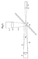
- FIG 1 provides a schematic illustration of a monitoring arrangement 1 in accordance with the present invention.
- a rotating component such as a fan disc 2
- a tracking apparatus 3 with an image 4 received from the component 2 through partial obscuration as a result of dust, flames light scatter etc.
- This partial obscuration is shown by lines 5 in Figure 1.
- targets in the form of retro reflectors 6 are secured to the rotating component 2.
- the tracking apparatus 3 monitors the rotating component 2 and generates images 4 which are compared to determine variations in displacement as the components are subject to various operational conditions.
- This monitoring of the component 2 as indicated can be during prototyping and design stages for a machine incorporating the rotating components such as illustrated within a gas turbine engine incorporating the fan blades in an arrangement and a rotating component 2 depicted in Figure 1.
- increasing light intensity is not appropriate as this may through polluting particles increase light scatter and the back ground light and therefore effectively blind the camera utilised within the tracking apparatus 3.
- FIG. 2 provides a schematic illustration of a tracker apparatus 13 in accordance with the present invention.
- the apparatus 13 incorporates a light source in the form of a laser 14 and a high-speed digital camera 15.
- the light source incorporates a lens 16 to project light towards a mirror 18 with an aperture 19.
- the camera 15 is associated with a filter and polariser combination 17 in order to appropriately present an image 20 to the camera 15.
- the laser 14 is associated an appropriate power source 21 whilst the camera 15 will be associated through a cable 22 with a controller whereby the images will be stored and compared as described later as well as provide for adjustment of the camera 15 made in order to achieve best results.
- the camera 15 is a high-speed digital camera with or without frame synchronised output.
- a high-speed shutter 23 may be used to improve image quality by opening and closing in conjunction with a pulsed light beam and thereby reducing background noise.
- the light source as indicated is normally a laser 14 which is divergent and may provide a continuous or pulsed light beam. Other laser types may be used to reduce back scatter. With laser choice dependant on wavelength and particle size.
- a light filter and polariser combination 17 is provided which matches with the laser wave length light source 14 as described above.
- targets in the form of retro reflectors 6 (figure 1) will be utilised in the present arrangement. These targets may be provided with a protective surface feature if required. Furthermore, where possible these targets may be designed for enhanced reflection at the wavelength of the light source 14.
- Camera images are relayed and stored in an appropriate storage facility of a controller for subsequent study. This may be through comparison of images. It may also be possible to provide determinations as to calculate fan orbit centre when it is difficult to find the centre of a rotating component. It should be appreciated that the retro-reflector 6 substantially reflects light back towards the light source, however a small angular deviation is necessary to avoid all the reflected light returning through the aperture 19 in mirror 18.
- an aperture 19 in the mirror 18 is preferred over a beam-splitter arrangement that could be placed in this position. This is due to the beam-splitter arrangement allowing a high level of background light to pass into the camera, which gives problems in separating the background laser light from the return laser light. Additionally the aperture in the mirror greatly aids maximising the light return from the retro-reflector to the camera. This is due to the return beam being slightly deviated by: a) lateral displacement of the return beam due to its path in the retro-reflector; b) diffraction caused by the finite aperture of the retro-reflector and the wavelength of light used and c) the imperfect build quality of the retro-reflector.
- the present arrangement allows identification of a rotating component orbit centre under very difficult, that is to say high light attenuation circumstances.
- a low divergence typically laser light signal, retro reflectors and the apertured mirror 18 it is possible to allow a high brightness signal to be captured by the camera 15 as the camera is not swamped and blinded by any scattered or background light.
- the present arrangement ensures a high signal to noise ratio over any background reflection or light signals from such sources as flames about a rotating component such as a blade assembly in a gas turbine engine.
- the centre of rotation is not accessible it is possible that multiple retro-reflectors will allow calculation of the rotating component dimensions by consideration of successive images received by the camera 15.
- accessibility is not a problem it may be possible to provide a situation where a single target in the form of a reflector could be fitted to the centre of the rotating component to act as a reference for image analysis.
- the retro reflected high intensity light beam from the laser 14 should be sufficient to overcome any large attenuation through dust or otherwise between the rotating component and the tracking apparatus.
- the targets 6 in accordance with the present invention are passive and will therefore not require a power source. In such circumstances the targets 6 will cause minimum additional weight and therefore will be less intrusive with regard to the results to be achieved.
- the use of several targets allows observation by image analysis and calculation of disc/object centres. As indicated previously through a known mathematical routine it is possible to calculate the centre of orbit of the rotating component. (If there are two or more known target positions).
- the mirror 18 is tilted and is generally at substantially forty-five degrees to the front of the rotating component. In such circumstances the light source laser 14 and camera 15 are then substantially in a perpendicular relationship about the aperture 19.
- the light source laser 14 and camera 15 are then substantially in a perpendicular relationship about the aperture 19.
- other optical angular presentations of the components may be achieved but will require active lens or other deflection mechanisms which may diminish light intensity particularly at optical interfaces and therefore capacity for high resolution.
- a beam splitter is not recommended for the reasons as hereinbefore described.
- the targets in the form of retro reflectors may be discrete components or specifically cut from a sheet of retro-reflective material and associated with the rotating component, or may even be for instance drilled bolt heads that perform the retro-reflection function.
- the light source laser may be continuous or pulsed to allow synchronisation to or with the camera in capturing images.
- the target is utilised in order to provide a reference within the image for comparison.
- the present arrangement can be utilised wherever there is a recognisable target feature for such image to image correlation.
- the arrangement has particular applicability where there is a poor transmissive medium such as through soot or dust or flame light signals, each of which are typical within a gas turbine engine, but where it is desirable to monitor a rotating component.
- the present arrangement has particular capability with respect to monitoring gas turbine engines either in prototype or service mode. Furthermore, as will be described later, it is possible to monitor these deflections relative to another reference such as a wing or fuselage position.
- the present arrangement has no direct contact with the rotating component and therefore can be considered non intrusive. If the centre of rotation is not directly available as the shaft exits on that centre of rotation the present arrangement may be used as an aid to shaft alignment. Furthermore, where a disc or partial disc has slid down a rotational shaft it will be appreciated that the present arrangement allows the position of the shaft centre to be found greatly aiding alignment of shafts in dirty or otherwise obscuring environments.
- Figure 3 provides a schematic illustration of the optical paths in accordance with the present arrangement. Consistent reference nomenclature to Figure 2 has been used for clarity.
- a light source 14 in the form of a laser is associated with the lens 16 in order to project an expanded light beam 30 towards a target retro reflector 6 ( Figure 1) and light is then reflected back along optical path 31 to become incident upon the mirror 18.
- the mirror 18 comprises a silvered plate such that the reflected light beam 31 is then deflected in the direction 31a to become incident upon the camera 15 through its lens 32.
- the camera 15 captures an image and this is stored as described above and used for comparison.
- the laser 14 may provide a continuous or pulsed light beam such that the camera 15 acquires images at different time periods as defined by a timer if the light beam is continuous or captures images for each light beam pulse from the laser 14.
- a single retro reflector is illustrated in Figure 3 but it would be appreciated that normally a rotating component will include a number of such reflectors to be deduced in the image captured by the camera 15 for analysis.
- an additional partial transmitting/reflective plate 40 may be placed at the entrance to a tracker apparatus 43. If the plate 40 is sufficiently tilted it can allow a reference target 45 to be observed coincidently with a retro reflected signal 44 from a rotating component 42. In such circumstances the reference point 45 will be shown in the image and utilised for reference with regard to other identifiable features in the image. It will be understood that the reference point should be accurately calibrated relative to the rotating component 42, but in any event will generally be stable in comparison with the rotating component 42. An example of utilisation of this refinement to the present arrangement would be to observe a position upon the ground adjacent the rotary component to ensure a reference for any observed movement in the rotatable component 42.
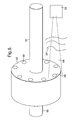
- a rotating component will have a number of targets or distinctive features in the form of retro reflectors.
- a rotating component 52 is secured upon a shaft 50 in order to rotate.
- a number of targets 56 are secured to the rotating component 52.
- a dusty environment 55 obscuring an image 54 received by a tracker apparatus 53 it will be understood that as the position of the targets 56 is known it will still be possible to identify movements and deflections in the shaft 58 in terms of centre of rotation for the rotating component 52 as well as with regard to other distortions provided these retro reflectors can still be identified in the image captured by the camera in the tracker apparatus 54.
- a shutter associated with the camera gives an advantage for the following reasons. When used with a pulsed light source it prevents the camera acquiring spurious and unnecessary light signals.
- the shutter being synchronised with the pulsed laser and or the camera.
- Such shutters may be any one of mechanical, electronic or as known to the skilled artisan. (see Figure 4).
- the rotating component in accordance with the present invention may be associated with targets such that movement of the rotating component to locate shaft centres as a function of axial position will not affect the ability of the monitoring arrangement to deduce displacements and distortions provided there is adequate reflection from the targets to allow capture of images by the camera. It will be understood that general operation of the present arrangement will ensure that the captured images from the camera are transferred to an appropriate controller and processor such that images can be compared in terms of position of targets and other distinct features in the rotating component in order to monitor that component.
- the present invention is also embodied by a method of calculating the co-ordinates of the centre of rotation of a body 2, 24 (such as the joined disc 2 and shaft 24 arrangement in figure 1) and thus an off-set between a body's 2, 24 rotational axis and its nominal central axis. This is particularly useful when the shaft 24 rotational axis itself is unobservable, for example when in use.
- An array of retro-reflectors 6 is placed on the disc 2, to which the shaft 24 is attached in known positions relative to the nominal physical rotational axis.
Landscapes
- Physics & Mathematics (AREA)
- General Physics & Mathematics (AREA)
- Health & Medical Sciences (AREA)
- Life Sciences & Earth Sciences (AREA)
- Chemical & Material Sciences (AREA)
- Analytical Chemistry (AREA)
- Biochemistry (AREA)
- General Health & Medical Sciences (AREA)
- Immunology (AREA)
- Pathology (AREA)
- Engineering & Computer Science (AREA)
- Multimedia (AREA)
- Signal Processing (AREA)
- Length Measuring Devices By Optical Means (AREA)
- Investigating Or Analysing Materials By Optical Means (AREA)
- Investigating Materials By The Use Of Optical Means Adapted For Particular Applications (AREA)
Applications Claiming Priority (1)
| Application Number | Priority Date | Filing Date | Title |
|---|---|---|---|
| GBGB0514108.0A GB0514108D0 (en) | 2005-07-08 | 2005-07-08 | A monitoring arrangement |
Publications (3)
| Publication Number | Publication Date |
|---|---|
| EP1742017A2 true EP1742017A2 (de) | 2007-01-10 |
| EP1742017A3 EP1742017A3 (de) | 2007-01-17 |
| EP1742017B1 EP1742017B1 (de) | 2007-08-29 |
Family
ID=34896978
Family Applications (1)
| Application Number | Title | Priority Date | Filing Date |
|---|---|---|---|
| EP06252996A Ceased EP1742017B1 (de) | 2005-07-08 | 2006-06-09 | Verfahren zum bestimmen der abweichung zwischen der drehachse eines körpers und seiner körperachse |
Country Status (4)
| Country | Link |
|---|---|
| US (1) | US7502128B2 (de) |
| EP (1) | EP1742017B1 (de) |
| DE (1) | DE602006000089T2 (de) |
| GB (1) | GB0514108D0 (de) |
Cited By (3)
| Publication number | Priority date | Publication date | Assignee | Title |
|---|---|---|---|---|
| DE102008024395A1 (de) * | 2008-05-20 | 2009-12-03 | Universität Karlsruhe (Th) | Verfahren zur Objekterfassung |
| GB2487931A (en) * | 2011-02-09 | 2012-08-15 | Rolls Royce Plc | Inspection of an engine component |
| CN104359866A (zh) * | 2014-11-24 | 2015-02-18 | 杭州远方光电信息股份有限公司 | 一种回复反射测量装置 |
Families Citing this family (7)
| Publication number | Priority date | Publication date | Assignee | Title |
|---|---|---|---|---|
| DE102009021557B4 (de) * | 2009-05-15 | 2016-08-04 | Airbus Defence and Space GmbH | Verfahren zur Bestimmung wenigstens einer Bewegungsgröße einer rotierenden Welle, Wellenuntersuchungs und/oder -überwachungsvorrichtung zu dessen Durchführung sowie Verwendung derselben |
| US9551620B2 (en) * | 2011-05-16 | 2017-01-24 | General Electric Company | Method and system for multi-functional embedded sensors |
| US10445871B2 (en) * | 2017-05-22 | 2019-10-15 | General Electric Company | Image analysis neural network systems |
| DE102019113154A1 (de) * | 2019-05-17 | 2020-11-19 | Schenck Rotec Gmbh | Verfahren und Vorrichtung zur Dehnungsmessung an einem fliehkraftbelasteten Körper |
| US12385412B2 (en) * | 2023-04-21 | 2025-08-12 | Rtx Corporation | Propulsor blade imaging assembly for an aircraft propulsion system |
| US12535312B2 (en) * | 2024-05-31 | 2026-01-27 | Rtx Corporation | White light interferometer for measuring radial growth in components experiencing rotating stresses |
| US12497899B1 (en) * | 2024-06-14 | 2025-12-16 | General Electric Company | Preventing abnormal fan blade deflection or fan flutter with retroreflectors |
Family Cites Families (10)
| Publication number | Priority date | Publication date | Assignee | Title |
|---|---|---|---|---|
| US4060329A (en) * | 1975-10-23 | 1977-11-29 | General Electric Company | Method and apparatus for measuring deflection of rotating airfoils |
| US4334777A (en) | 1976-07-26 | 1982-06-15 | Aerodyne Research, Inc. | Method of monitoring motion |
| US4086808A (en) | 1976-07-26 | 1978-05-02 | Aerodyne Research, Inc. | Motion detection and measurement |
| US4080823A (en) * | 1976-11-05 | 1978-03-28 | United Technologies Corporation | Vibration measurement |
| JPS56111407A (en) | 1980-02-08 | 1981-09-03 | Toshiba Corp | Shaft torsion detecting method |
| GB2178165B (en) * | 1985-07-24 | 1989-08-09 | Rolls Royce Plc | Optical monitoring method and apparatus |
| JPH02185602A (ja) * | 1989-01-11 | 1990-07-20 | Mitsubishi Heavy Ind Ltd | 動翼先端すき間計測装置 |
| JP2846117B2 (ja) * | 1991-06-13 | 1999-01-13 | プリューフテヒニーク ディーター ブッシュ アクチェンゲゼルシャフト | 湾曲軸線を決定するための方法および装置 |
| JPH0861917A (ja) * | 1994-08-18 | 1996-03-08 | S K S Kk | 位置検知装置 |
| IL125659A (en) * | 1998-08-05 | 2002-09-12 | Cadent Ltd | Method and device for three-dimensional simulation of a structure |
-
2005
- 2005-07-08 GB GBGB0514108.0A patent/GB0514108D0/en not_active Ceased
-
2006
- 2006-06-09 EP EP06252996A patent/EP1742017B1/de not_active Ceased
- 2006-06-09 DE DE602006000089T patent/DE602006000089T2/de active Active
- 2006-06-12 US US11/450,335 patent/US7502128B2/en active Active
Cited By (3)
| Publication number | Priority date | Publication date | Assignee | Title |
|---|---|---|---|---|
| DE102008024395A1 (de) * | 2008-05-20 | 2009-12-03 | Universität Karlsruhe (Th) | Verfahren zur Objekterfassung |
| GB2487931A (en) * | 2011-02-09 | 2012-08-15 | Rolls Royce Plc | Inspection of an engine component |
| CN104359866A (zh) * | 2014-11-24 | 2015-02-18 | 杭州远方光电信息股份有限公司 | 一种回复反射测量装置 |
Also Published As
| Publication number | Publication date |
|---|---|
| DE602006000089D1 (de) | 2007-10-11 |
| GB0514108D0 (en) | 2005-08-17 |
| DE602006000089T2 (de) | 2008-01-03 |
| EP1742017A3 (de) | 2007-01-17 |
| US7502128B2 (en) | 2009-03-10 |
| US20070009252A1 (en) | 2007-01-11 |
| EP1742017B1 (de) | 2007-08-29 |
Similar Documents
| Publication | Publication Date | Title |
|---|---|---|
| US7502128B2 (en) | Monitoring arrangement for rotating components | |
| JP2011141296A (ja) | 近接度検出器 | |
| NO890430L (no) | Fremgangsmaate og apparat for maaling av innsiktingsgrad for elektro- og optiske systemer. | |
| US7948613B2 (en) | Optical device for measuring moving speed of an object relative to a surface | |
| WO2010010311A2 (fr) | Dispositif optique et procede de mesure de rotation d'un objet | |
| CN103558412B (zh) | 用于流场的干涉瑞利散射测速装置 | |
| CN103376265A (zh) | 物品缺陷检测系统与方法 | |
| US4049336A (en) | Pulsed holographic system having independent universal beam adjustment | |
| US7206066B2 (en) | Reflectance surface analyzer | |
| EP3111188B1 (de) | Optisches instrument zur identifizierung und lokalisierung von mikroätzung auf einer ophthalmischen linse | |
| CN205899008U (zh) | 基于马赫曾德干涉仪的激光鉴频装置 | |
| JPH07502810A (ja) | 光学系内の境界面の傾斜を測定する方法及び装置 | |
| US20120057172A1 (en) | Optical measuring system with illumination provided through a void in a collecting lens | |
| EP0731335B1 (de) | Vorrichtung und Verfahren zum zerstörungsfreien Testen von mit Kohärenzlicht bestrahlten Materialien | |
| JP4255586B2 (ja) | 試料検査装置 | |
| US7964834B2 (en) | Low backscatter test method and apparatus | |
| JP2005106820A (ja) | 光沢面測定のための協調偏光 | |
| US7443518B2 (en) | Measuring instrument, in particular for transmission measurement in vacuum system | |
| US12535312B2 (en) | White light interferometer for measuring radial growth in components experiencing rotating stresses | |
| FR2909182A1 (fr) | Procede et dispositif pour la detection d'un objet apte a retroreflechir la lumiere | |
| JPH09113211A (ja) | ノイズ防止機能付干渉計 | |
| JP2000105101A (ja) | 斜入射干渉計装置 | |
| FR2972051A1 (fr) | Banc de controle simplifie de telescopes et telescopes auto-controlables | |
| Gu et al. | Design review of a unique laser monostatic bidirectional reflectometer | |
| FR3041767A1 (fr) | Procede de detection d'obstacles et vehicule muni d'un systeme de detection d'obstacles |
Legal Events
| Date | Code | Title | Description |
|---|---|---|---|
| PUAI | Public reference made under article 153(3) epc to a published international application that has entered the european phase |
Free format text: ORIGINAL CODE: 0009012 |
|
| PUAL | Search report despatched |
Free format text: ORIGINAL CODE: 0009013 |
|
| AK | Designated contracting states |
Kind code of ref document: A2 Designated state(s): AT BE BG CH CY CZ DE DK EE ES FI FR GB GR HU IE IS IT LI LT LU LV MC NL PL PT RO SE SI SK TR |
|
| AX | Request for extension of the european patent |
Extension state: AL BA HR MK YU |
|
| AK | Designated contracting states |
Kind code of ref document: A3 Designated state(s): AT BE BG CH CY CZ DE DK EE ES FI FR GB GR HU IE IS IT LI LT LU LV MC NL PL PT RO SE SI SK TR |
|
| AX | Request for extension of the european patent |
Extension state: AL BA HR MK YU |
|
| RIC1 | Information provided on ipc code assigned before grant |
Ipc: G01B 11/16 20060101ALI20061213BHEP Ipc: G01B 11/27 20060101AFI20061026BHEP |
|
| 17P | Request for examination filed |
Effective date: 20061229 |
|
| 17Q | First examination report despatched |
Effective date: 20070226 |
|
| GRAP | Despatch of communication of intention to grant a patent |
Free format text: ORIGINAL CODE: EPIDOSNIGR1 |
|
| RTI1 | Title (correction) |
Free format text: A METHOD OF FINDING THE OFF-SET BETWEEN A BODY'S ROTATIONAL AXIS AND ITS NOMINAL AXIS |
|
| GRAS | Grant fee paid |
Free format text: ORIGINAL CODE: EPIDOSNIGR3 |
|
| GRAA | (expected) grant |
Free format text: ORIGINAL CODE: 0009210 |
|
| AK | Designated contracting states |
Kind code of ref document: B1 Designated state(s): DE FR GB |
|
| REG | Reference to a national code |
Ref country code: GB Ref legal event code: FG4D |
|
| AKX | Designation fees paid |
Designated state(s): DE FR GB |
|
| REF | Corresponds to: |
Ref document number: 602006000089 Country of ref document: DE Date of ref document: 20071011 Kind code of ref document: P |
|
| ET | Fr: translation filed | ||
| PLBE | No opposition filed within time limit |
Free format text: ORIGINAL CODE: 0009261 |
|
| STAA | Information on the status of an ep patent application or granted ep patent |
Free format text: STATUS: NO OPPOSITION FILED WITHIN TIME LIMIT |
|
| 26N | No opposition filed |
Effective date: 20080530 |
|
| REG | Reference to a national code |
Ref country code: FR Ref legal event code: PLFP Year of fee payment: 10 |
|
| REG | Reference to a national code |
Ref country code: FR Ref legal event code: PLFP Year of fee payment: 11 |
|
| REG | Reference to a national code |
Ref country code: FR Ref legal event code: PLFP Year of fee payment: 12 |
|
| REG | Reference to a national code |
Ref country code: FR Ref legal event code: PLFP Year of fee payment: 13 |
|
| PGFP | Annual fee paid to national office [announced via postgrant information from national office to epo] |
Ref country code: FR Payment date: 20200626 Year of fee payment: 15 |
|
| PGFP | Annual fee paid to national office [announced via postgrant information from national office to epo] |
Ref country code: GB Payment date: 20200629 Year of fee payment: 15 |
|
| PGFP | Annual fee paid to national office [announced via postgrant information from national office to epo] |
Ref country code: DE Payment date: 20200827 Year of fee payment: 15 |
|
| REG | Reference to a national code |
Ref country code: DE Ref legal event code: R119 Ref document number: 602006000089 Country of ref document: DE |
|
| GBPC | Gb: european patent ceased through non-payment of renewal fee |
Effective date: 20210609 |
|
| PG25 | Lapsed in a contracting state [announced via postgrant information from national office to epo] |
Ref country code: GB Free format text: LAPSE BECAUSE OF NON-PAYMENT OF DUE FEES Effective date: 20210609 Ref country code: DE Free format text: LAPSE BECAUSE OF NON-PAYMENT OF DUE FEES Effective date: 20220101 |
|
| PG25 | Lapsed in a contracting state [announced via postgrant information from national office to epo] |
Ref country code: FR Free format text: LAPSE BECAUSE OF NON-PAYMENT OF DUE FEES Effective date: 20210630 |