EP1741503B1 - Method of manufacturing a rocker arm - Google Patents
Method of manufacturing a rocker arm Download PDFInfo
- Publication number
- EP1741503B1 EP1741503B1 EP06116312A EP06116312A EP1741503B1 EP 1741503 B1 EP1741503 B1 EP 1741503B1 EP 06116312 A EP06116312 A EP 06116312A EP 06116312 A EP06116312 A EP 06116312A EP 1741503 B1 EP1741503 B1 EP 1741503B1
- Authority
- EP
- European Patent Office
- Prior art keywords
- side wall
- portions
- projecting
- rocker arm
- subjected
- Prior art date
- Legal status (The legal status is an assumption and is not a legal conclusion. Google has not performed a legal analysis and makes no representation as to the accuracy of the status listed.)
- Not-in-force
Links
- 238000004519 manufacturing process Methods 0.000 title claims abstract description 19
- 238000000034 method Methods 0.000 claims abstract description 60
- 230000008569 process Effects 0.000 claims abstract description 57
- 238000012545 processing Methods 0.000 claims abstract description 40
- 230000015572 biosynthetic process Effects 0.000 claims abstract description 16
- 238000010409 ironing Methods 0.000 claims abstract description 16
- 238000010273 cold forging Methods 0.000 claims abstract description 14
- 238000005452 bending Methods 0.000 claims description 9
- 238000009966 trimming Methods 0.000 claims description 9
- 238000003825 pressing Methods 0.000 claims description 6
- 239000002184 metal Substances 0.000 description 6
- 239000011265 semifinished product Substances 0.000 description 6
- 230000007547 defect Effects 0.000 description 5
- 230000008901 benefit Effects 0.000 description 3
- 238000005520 cutting process Methods 0.000 description 3
- 238000005242 forging Methods 0.000 description 3
- 238000012546 transfer Methods 0.000 description 3
- 102000010029 Homer Scaffolding Proteins Human genes 0.000 description 2
- 108010077223 Homer Scaffolding Proteins Proteins 0.000 description 2
- 230000008859 change Effects 0.000 description 2
- 230000001050 lubricating effect Effects 0.000 description 2
- 230000007246 mechanism Effects 0.000 description 2
- 229910019142 PO4 Inorganic materials 0.000 description 1
- 229910000831 Steel Inorganic materials 0.000 description 1
- 238000002485 combustion reaction Methods 0.000 description 1
- 230000003247 decreasing effect Effects 0.000 description 1
- 238000011161 development Methods 0.000 description 1
- 230000000694 effects Effects 0.000 description 1
- 230000006872 improvement Effects 0.000 description 1
- 238000012986 modification Methods 0.000 description 1
- 230000004048 modification Effects 0.000 description 1
- 230000002093 peripheral effect Effects 0.000 description 1
- NBIIXXVUZAFLBC-UHFFFAOYSA-K phosphate Chemical compound [O-]P([O-])([O-])=O NBIIXXVUZAFLBC-UHFFFAOYSA-K 0.000 description 1
- 239000010452 phosphate Substances 0.000 description 1
- 239000000047 product Substances 0.000 description 1
- 230000006641 stabilisation Effects 0.000 description 1
- 238000011105 stabilization Methods 0.000 description 1
- 239000010959 steel Substances 0.000 description 1
- 238000004804 winding Methods 0.000 description 1
Images








Classifications
-
- B—PERFORMING OPERATIONS; TRANSPORTING
- B21—MECHANICAL METAL-WORKING WITHOUT ESSENTIALLY REMOVING MATERIAL; PUNCHING METAL
- B21K—MAKING FORGED OR PRESSED METAL PRODUCTS, e.g. HORSE-SHOES, RIVETS, BOLTS OR WHEELS
- B21K1/00—Making machine elements
- B21K1/20—Making machine elements valve parts
- B21K1/205—Making machine elements valve parts rocker arms
-
- F—MECHANICAL ENGINEERING; LIGHTING; HEATING; WEAPONS; BLASTING
- F01—MACHINES OR ENGINES IN GENERAL; ENGINE PLANTS IN GENERAL; STEAM ENGINES
- F01L—CYCLICALLY OPERATING VALVES FOR MACHINES OR ENGINES
- F01L1/00—Valve-gear or valve arrangements, e.g. lift-valve gear
- F01L1/12—Transmitting gear between valve drive and valve
- F01L1/18—Rocking arms or levers
- F01L1/185—Overhead end-pivot rocking arms
-
- F—MECHANICAL ENGINEERING; LIGHTING; HEATING; WEAPONS; BLASTING
- F01—MACHINES OR ENGINES IN GENERAL; ENGINE PLANTS IN GENERAL; STEAM ENGINES
- F01L—CYCLICALLY OPERATING VALVES FOR MACHINES OR ENGINES
- F01L2303/00—Manufacturing of components used in valve arrangements
-
- F—MECHANICAL ENGINEERING; LIGHTING; HEATING; WEAPONS; BLASTING
- F01—MACHINES OR ENGINES IN GENERAL; ENGINE PLANTS IN GENERAL; STEAM ENGINES
- F01L—CYCLICALLY OPERATING VALVES FOR MACHINES OR ENGINES
- F01L2305/00—Valve arrangements comprising rollers
-
- Y—GENERAL TAGGING OF NEW TECHNOLOGICAL DEVELOPMENTS; GENERAL TAGGING OF CROSS-SECTIONAL TECHNOLOGIES SPANNING OVER SEVERAL SECTIONS OF THE IPC; TECHNICAL SUBJECTS COVERED BY FORMER USPC CROSS-REFERENCE ART COLLECTIONS [XRACs] AND DIGESTS
- Y10—TECHNICAL SUBJECTS COVERED BY FORMER USPC
- Y10T—TECHNICAL SUBJECTS COVERED BY FORMER US CLASSIFICATION
- Y10T29/00—Metal working
- Y10T29/49—Method of mechanical manufacture
- Y10T29/49229—Prime mover or fluid pump making
- Y10T29/49295—Push rod or rocker arm making
-
- Y—GENERAL TAGGING OF NEW TECHNOLOGICAL DEVELOPMENTS; GENERAL TAGGING OF CROSS-SECTIONAL TECHNOLOGIES SPANNING OVER SEVERAL SECTIONS OF THE IPC; TECHNICAL SUBJECTS COVERED BY FORMER USPC CROSS-REFERENCE ART COLLECTIONS [XRACs] AND DIGESTS
- Y10—TECHNICAL SUBJECTS COVERED BY FORMER USPC
- Y10T—TECHNICAL SUBJECTS COVERED BY FORMER US CLASSIFICATION
- Y10T29/00—Metal working
- Y10T29/51—Plural diverse manufacturing apparatus including means for metal shaping or assembling
- Y10T29/5116—Plural diverse manufacturing apparatus including means for metal shaping or assembling forging and bending, cutting or punching
-
- Y—GENERAL TAGGING OF NEW TECHNOLOGICAL DEVELOPMENTS; GENERAL TAGGING OF CROSS-SECTIONAL TECHNOLOGIES SPANNING OVER SEVERAL SECTIONS OF THE IPC; TECHNICAL SUBJECTS COVERED BY FORMER USPC CROSS-REFERENCE ART COLLECTIONS [XRACs] AND DIGESTS
- Y10—TECHNICAL SUBJECTS COVERED BY FORMER USPC
- Y10T—TECHNICAL SUBJECTS COVERED BY FORMER US CLASSIFICATION
- Y10T74/00—Machine element or mechanism
- Y10T74/20—Control lever and linkage systems
- Y10T74/20576—Elements
- Y10T74/20882—Rocker arms
Definitions
- the present invention relates to a method of manufacturing a rocker arm for valve gears of internal combustion engines from a metallic stock, as per the preamble of claim 1.
- JP-A-6-159018 a method of manufacturing a rocker arm, in which a stock is changed in thickness to be subjected to forge processing to make a pat, a pivot bearing, and a pair of sides in a predetermined shape of development, peripheral edges of the sides are subjected to stamping to have a predetermined shape, and thereafter, the sides are subjected to bending to be made upright to form side wall portions.
- a roller is mounted rotatably on the both side wall portions.
- Japanese Laid-open Patent Publication Number hei 10-328778 discloses a method of manufacturing a rocker arm having a flat, relatively long and narrow shape, in which a multi-stage horizontal, cold forging machine is used to subject a metallic wire rod having a rectangular-shaped section to compression-forming in a diametrical direction by cold forging to form a connecting portion and a side wall portion, which are a little low in dimensional accuracy, and thereafter a connecting portion and a side wall portion, which are high in dimensional accuracy, are formed.
- Japanese Laid-open Patent Publication Number 2004-358530 discloses a method of manufacturing a rocker arm, in which a multi-stage horizontal, cold forging machine is used to shape a metallic wire rod, having a circular-shaped section, into a drum form, the rod is subjected to compression-forming from both sides in a diametrical direction by cold forging to form a connecting portion and a side wall portion, which are rough in shape and dimension, and thereafter a connecting portion and a side wall portion, which are further close to a finished product in terms of shape and dimension.
- the object of the invention is to form side wall portions without generation of defects such as crack, breakage, etc. on a metallic stock and a further object of the invention is to form stem guides which project a large height downwardly and have a high accuracy.
- the object is solved by the features defined in claim 1.
- the metallic stock is not specifically limited in shape. While the metallic stock is preferably inexpensive and especially preferably circular in section, a metallic stock being rectangular in section may be employed.
- the invention is especially suited to manufacture of a rocker arm, in which a height of side wall portions is comparatively large relative to a length of the rocker arm (specifically, 30 to 50 % of the length of the rocker arm). It is possible to provide a rocker arm, in which side wall portions are made high and a roller is mounted in a high position relative to a spherical-shaped recess and a pat surface of the connecting portion.
- a metallic stock (32) is subjected to compression-forming by cold forging to form a connecting portion (4, 5, 13), side wall lower portions (3a) of two side wall portions (3), and two projecting portions (14) projecting beyond a rocker arm width outwardly from the side wall lower portions (3a), and to form, at tip ends of the side wall lower portions (3a), two stem guides (9) projecting downwardly lower than a pat surface (8) level of the connecting portion (5) (a process of rough processing).
- At least a part of the two projecting portions (14) is subjected to ironing processing to form side wall upper portions (3b) of the two side wall portions (3), thereby forming the two side wall portions (3) accommodated in a rocker arm width (a process of formation of a side wall).
- the two side wall portions (3) are subjected to ironing processing from outer surface sides, thereby increasing a projection height from which the stem guides (8) project downwardly (a process of working of a stem guide).
- Figs. 1A to 8C show an embodiment 1 of the invention.
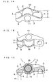
- Figs. 1A to 1C show a rocker arm 1 with a roller manufactured by a method of the present embodiment, the rocker arm 1 comprising an arm body 2 and a roller 10.
- the arm body 2 is formed integrally by two upright side wall portions 3 which face each other with a spacing therebetween, a base end side connecting portion 4 which connects between lower portions of both the side wall portions 3 on a base end side, and a tip end side connecting portion 5 which connects between lower portions of both the side wall portions 3 on a tip end side.
- a through window 6 being rectangular in plan is defined between the base end side connecting portion 4 and the tip end side connecting portion 5.
- the base end side connecting portion 4 is a pivot bearing in the form of a larger block than that of the tip end side connecting portion 5.
- a spherical-shaped recess 7 into which a spherical-shaped head P of a pivot shaft is fitted.
- the tip end side connecting portion 5 is a pat in the form of a smaller block than that of the base end side connecting portion 4, and a lower surface thereof defines a convexly curved pat surface 8 to push a valve stem V.
- a stem guide 9 Formed on each of tip end lower portions of the two side wall portions 3 is a stem guide 9 to project downwardly lower than the level of the pat surface 8 to interpose an end of the valve stem V.
- a roller 10 Arranged between the both sidewall portions 3 is a roller 10 that abuts against a cam C.
- the roller 10 is mounted rotatably on a spindle 11 which passes through the both side wall portions 3, by a bearing 12.
- a rocker arm width being a distance between outer surfaces of the two side wall portions 3 is a rocker arm width W being substantially constant in a major part of rocker arm except both longitudinal ends, and narrowed at both ends.
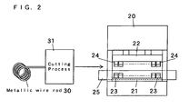
- a vertical type multi-stage transfer press 20 as shown in, for example, Fig. 2 can be suitably used.
- the vertical type press has an advantage that it can readily include eight or more multi-stages.
- the transfer press 20 in the example as shown is equipped with a horizontal stationary board 21 being disposed on a lower side to be long left and right, and a horizontal movable board 22 being disposed on an upper side to be long left and right.
- the movable board 22 is driven by a drive device to move up and down, and all the movable dies 24 move up and down together with the movable board 22.
- 25 denotes a conveyance mechanism.
- a metallic wire rod 30 having a circular-shaped section (for example, a diameter of 16 mm) is usually handled in a state of coil winding, and the metallic wire rod 30 in this state is supported on a rotary support member (not shown).
- the metallic wire rod 30 is unwounded starting at one end thereof to be pulled out to be fed to a homer 31.
- the metallic wire rod 30 is cut into a predetermined length (for example, 40 mm).
- a columnar-shaped metallic wire rod 32 thus cut may be annealed to achieve softening, stress relieving, stabilization of structure, etc., or may not be annealed.
- a lubricating film may be formed to achieve an improvement in formability by , for example, phosphate processing, or the lubricating film may not be formed.
- the cutting process may be performed as a first process of the multi-stage press.
- the above metallic wire rod 32 is fed to the multi-stage transfer press 20 and the conveyance mechanism 25 successively conveys the metallic wire rod 32 and its semi-finished product to a next stage from a stage, and the following process of rough processing, a process of trimming, and a process of formation of a side wall are consecutively performed by the multi-stage simultaneous press.
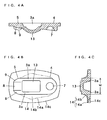
- the base end side connecting portion 4, the tip end side connecting portion 5, and the intermediate connecting portion 13 are continuous, and a central portion in the width direction of the intermediate connecting portion 13 projects downwardly in a stepped manner.
- Inner surfaces of the side wall lower portions 3a are inclined as being tapered downwardly, and comprise inclined portions 3c which exceed a thickness of the side wall portions 3.
- the projecting portion 14 in the present embodiment comprise a flange 14a bent at right angle from an outer surface of an upper end of the side wall lower portion 3a to project, and a curved fillet 14b provided between a lower surface of the flange 14a and the outer surface of the upper end of the side wall lower portion 3a.
- the both portions 14a, 14b are unitary with each other and no boundary is substantially present therebetween.
- the flange 14a has a surplus portion 14c projecting excessively beyond a necessary amount of projection up to an extent indicated by a two-dot chain line shown in Figs. 4A to 4C .
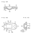
- the projecting portion 14 having a necessary amount of projection is left by cutting out the surplus portion 14C by press stamping.
- metal flow is generated in necessary portions by ironing the fillets 14b on outer surface sides and pressing the inclined portions 3c on the inner surface sides in addition to bending of the flanges 14a, there is no fear that defects such as crack, etc. are generated on the base ends of the side wall upper portions 3b.
- the intermediate connecting portion 13 is stamped by press stamping to form a window 6.
- the present process may be omitted to leave the intermediate connecting portion 13.
- shaft holes are formed in the two side wall portions 3, the roller 10 is arranged between the two side wall portions 3 and in the window 6, and the roller 10 is mounted rotatably on that spindle 11 which passes through the shaft holes, by the bearing 12.
- Figs. 9A to 12D show an embodiment 2 of the invention.
- the present embodiment is different from the embodiment 1 only in that projecting portions 14 being worked by rough processing are changed in shape to decrease surplus portions 14c cut out by trim processing, and a process of formation of a side wall is performed with ironing processing and pressing processing (bending process is not performed), and common to the embodiment 1 in other processes and the structure of a rocker arm 1 being manufactured.
- the present embodiment is common to the embodiment 1 in that a base end side connecting portion 4, a tip end side connecting portion 5, an intermediate connecting portion 13, side wall lower portions 3a, projecting portions 14, and stem guides 9 are formed by compression-forming a metallic wire rod 32 shown in Figs. 9A and 9B in a diametrical direction by cold forging as shown in Figs. 10A to 10C .
- the side wall lower portions 3a are formed to be higher than those in the embodiment 1, while an amount of projection of flanges 14a is made smaller than that in the embodiment 1 and surplus portions 14c are decreased compared with that in the embodiment 1.
- the surplus portions 14c are cut out to trim the flanges 14a of the projecting portions 14 to the same extent as the amount of projection of fillets 14b, thereby making the projecting portions 14 having a necessary amount of projection.
- the trimmed flanges 14a and the fillets 14b of the projecting portions 14 are subjected to ironing inwardly, and inclined portions 3c on inner surfaces of the side wall lower portions 3a are subjected to pressing processing, so that metal flow is generated to form side wall upper portions 3b of two side wall portions 3 and hence the two side wall portions 3 accommodated in a rocker arm width are formed. Also, in the present embodiment, there is no fear that defects such as crack, etc. are generated on base ends of the side wall upper portions 3b.
- the rocker arm 1 having the same structure as that of the embodiment 1 can be obtained by performing the subsequent processes in the same manner as in the embodiment 1.
- Figs. 13A to 17C show an embodiment 3 of the invention.
- the present embodiment is different from the embodiment 2 only in that projecting portions 14 obtained in the trim processing of the embodiment 2 are formed in rough processing to dispense with the process of trimming, and common to the embodiment 1 in other processes and the structure of a rocker arm 1 being manufactured.
- a metallic wire rod 32 shown in Figs. 13A and 13B is first subjected to compression-forming in a longitudinal direction (axial direction) by cold forging, whereby a central portion in the longitudinal direction is bulged as shown in Fig. 14 .
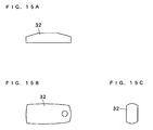
- the metallic wire rod 32 thus bulged is subjected to compression-forming in a diametrical direction by cold forging to be made a flat block, of which the central portion in the longitudinal direction is also bulged in a widthwise direction and in a thickness direction as shown in Figs. 15A to 15C .
- the flat block is subjected to compression-forming to be made similar in shape to an arm body 2 as shown in Figs. 16A and 16B , and further subjected to compression-forming to form projecting portions 14 having only a necessary amount of projection as shown in Figs. 17A to 17C .
- projecting portions 14 having a necessary amount of projection are formed while volume adjustment of a metallic stock is achieved in rough processing by plural stages of compression-forming, so that there is an advantage that the process of trimming is dispensed with.
- the rocker arm having the same structure as that of the embodiment 1 can be obtained by performing the subsequent processes in the same manner as in the embodiment 2.
Landscapes
- Engineering & Computer Science (AREA)
- Mechanical Engineering (AREA)
- General Engineering & Computer Science (AREA)
- Valve-Gear Or Valve Arrangements (AREA)
- Forging (AREA)
Abstract
Description
- The present invention relates to a method of manufacturing a rocker arm for valve gears of internal combustion engines from a metallic stock, as per the preamble of claim 1.
- In many rocker arms (in particular, rocker arms with a roller), a pat which pushes a valve stem, and a pivot bearing which bears a pivot, make a connecting portion, and there are provided two side wall portions upright from both ends of the connecting portion. The applicant of the present application has previously disclosed in
Japanese Laid-open Patent Publication Number hei 06-159018 JP-A-6-159018 - Also,
Japanese Laid-open Patent Publication Number hei 10-328778 JP-A-10-328778 - Also,
Japanese Laid-open Patent Publication Number 2004-358530 JP-A-2004-358530 - In the manufacturing method of
JP-A-6-159018 - In the manufacturing methods of
JP-A-10-328778 JP-A-2004-358530 - Also, while two stem guides projecting downwardly lower than a pat level are formed on both sides of the pat, the manufacturing methods of
JP-A-6-159018 JP-A-10-328778 JP-A-2004-358530 - Therefore, the object of the invention is to form side wall portions without generation of defects such as crack, breakage, etc. on a metallic stock and a further object of the invention is to form stem guides which project a large height downwardly and have a high accuracy. The object is solved by the features defined in claim 1.
- Here, the metallic stock is not specifically limited in shape. While the metallic stock is preferably inexpensive and especially preferably circular in section, a metallic stock being rectangular in section may be employed.
- Two embodiments for obtaining a projecting portion having only a necessary amount of projection are illustrated as follows.
- (i) An embodiment, in which two projecting portions, each including a surplus portion projecting excessively beyond a necessary amount of projection, are formed in the process of rough processing, and after the process of rough processing and prior to the process of formation of the side wall, a process of trimming, in which the surplus portion is cut out to make the projecting portion having only a necessary amount of projection, is performed.
- (ii) An embodiment, in which a metallic stock is subjected to compression-forming in multi-stages to form two projecting portions having only a necessary amount of projection in the process of rough processing. Compression-forming described later in an
embodiment 3 can be illustrated. In this embodiment, a process of trimming can be dispensed with. - While the process of formation of the side wall may be performed only by ironing processing, the following embodiment can be illustrated.
- (a) An embodiment comprising bending, in which separate portions of two projecting portions are bent upright, in addition to the ironing processing of the projecting portion.
- (b) An embodiment comprising pressing, in which inner surfaces of lower portions of two side walls are pressed, in addition to the ironing processing of the projecting portion.
- The invention is especially suited to manufacture of a rocker arm, in which a height of side wall portions is comparatively large relative to a length of the rocker arm (specifically, 30 to 50 % of the length of the rocker arm). It is possible to provide a rocker arm, in which side wall portions are made high and a roller is mounted in a high position relative to a spherical-shaped recess and a pat surface of the connecting portion.
- According to the invention, it is possible to form side wall portions without generation of defects such as crack, breakage, etc. on a metallic stock. According to the invention, it is possible to form stem guides having a large projection height downwardly and having a high accuracy. According to the invention, it is possible to attain these effects in combination.
- Further objects of this invention will become evident upon an understanding of the illustrative embodiments described below. Various advantages not specifically referred to herein but within the scope of the instant claims will occur to one skilled in the art upon practice of the presently disclosed invention. The following examples and embodiments are illustrative and not seen to limit the scope of the claims.
-
Figs. 1A to 1C show a rocker arm manufactured by an embodiment of the invention,Fig. 1A being a perspective view as viewed from above,Fig. 1B being a perspective view as viewed from under, andFig. 1C being a cross sectional view; -
Fig. 2 is a schematic view showing an apparatus used in a manufacturing method; -
Figs. 3A and 3B show a metallic wire rod used in an embodiment 1,Fig. 3A being a front view, andFig. 3B being an end view; -
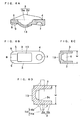
Figs. 4A to 4C show a semi-finished product of an arm body formed by a process of rough processing of the embodiment 1,Fig. 4A being a cross sectional view,Fig. 4b being a bottom view, andFig. 4c being a transverse, cross sectional view; -
Figs. 5A to 5C show a semi-finished product of an arm body formed by a process of trimming of the embodiment 1,Fig. 5A being a cross sectional view,Fig. 5B being a bottom view, andFig. 5C being a transverse, cross sectional view; -
Figs. 6A to 6D show a semi-finished arm body formed by a process of formation of the side wall of the embodiment 1,Fig. 6A being a cross sectional view,Fig. 6B being a bottom view,Fig. 6C being a transverse, cross sectional view, andFig. 6D being an enlarged, transverse, cross sectional view showing a change from a preprocess (chain line); -
Figs. 7A to 7C show a semi-finished arm body formed by a process of formation of a window of the embodiment 1,Fig. 7A being a cross sectional view,Fig. 7B being a bottom view, andFig. 7C being a transverse, cross sectional view; -
Figs. 8A to 8C show an arm body formed by a process of working of a stem guide of the embodiment 1,Fig. 8A being a cross sectional view,Fig. 8B being a bottom view, andFig. 8C being a transverse, cross sectional view; -
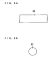
Figs. 9A and 9B show a metallic wire rod used in anembodiment 2,Fig. 9A being a front view, andFig. 9B being an end view; -
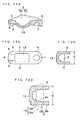
Figs. 10A to 10C show a semi-finished product of an arm body formed by a process of rough processing of theembodiment 2,Fig. 10A being a cross sectional view,Fig. 10B being a bottom view, andFig. 10C being a transverse, cross sectional view; -
Figs. 11A to 11C show a semi-finished product of an arm body formed by a process of trimming of theembodiment 2,Fig. 11A being a cross sectional view,Fig. 11B being a bottom view, andFig. 11C being a transverse, cross sectional view; -
Figs. 12A to 12D show an arm body formed by a process of formation of the side wall of theembodiment 2,Fig. 12A being a cross sectional view,Fig. 12B being a bottom view,Fig. 12C being a transverse, cross sectional view, andFig. 12D being an enlarged, transverse, cross sectional view showing a change from a preprocess (chain line); -
Figs. 13A and 13B show a metallic wire rod used in anembodiment 3,Fig. 13A being a front view, andFig. 13B being an end view; -
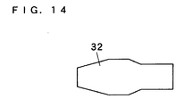
Fig. 14 is a front view showing a metallic wire rod subjected to compression-forming in an axial direction in a process of rough processing; -
Figs. 15A to 15C show a metallic wire rod further subjected to compression-forming in a diametrical direction ,Fig. 15A being a front view,Fig. 15B being a bottom view, andFig. 15C being a side view; -
Figs. 16A and 16B show a metallic wire rod further subjected to compression-forming,Fig. 16A being a front view, andFig. 16B being a bottom view; and -
Figs. 17A to 17C show a semi-finished product of an arm body further subjected to compression-forming,Fig. 17A being a cross sectional view,Fig. 17B being a bottom view, andFig. 17C being a transverse, cross sectional view. - A metallic stock (32) is subjected to compression-forming by cold forging to form a connecting portion (4, 5, 13), side wall lower portions (3a) of two side wall portions (3), and two projecting portions (14) projecting beyond a rocker arm width outwardly from the side wall lower portions (3a), and to form, at tip ends of the side wall lower portions (3a), two stem guides (9) projecting downwardly lower than a pat surface (8) level of the connecting portion (5) (a process of rough processing).
- Next, at least a part of the two projecting portions (14) is subjected to ironing processing to form side wall upper portions (3b) of the two side wall portions (3), thereby forming the two side wall portions (3) accommodated in a rocker arm width (a process of formation of a side wall).
- Moreover, the two side wall portions (3) are subjected to ironing processing from outer surface sides, thereby increasing a projection height from which the stem guides (8) project downwardly (a process of working of a stem guide).
-
Figs. 1A to 8C show an embodiment 1 of the invention.Figs. 1A to 1C show a rocker arm 1 with a roller manufactured by a method of the present embodiment, the rocker arm 1 comprising anarm body 2 and aroller 10. Thearm body 2 is formed integrally by two uprightside wall portions 3 which face each other with a spacing therebetween, a base endside connecting portion 4 which connects between lower portions of both theside wall portions 3 on a base end side, and a tip endside connecting portion 5 which connects between lower portions of both theside wall portions 3 on a tip end side. According to the present embodiment, a throughwindow 6 being rectangular in plan is defined between the base endside connecting portion 4 and the tip endside connecting portion 5. - The base end
side connecting portion 4 is a pivot bearing in the form of a larger block than that of the tip endside connecting portion 5. At a lower surface of the base endside connecting portion 4, there is formed a spherical-shapedrecess 7, into which a spherical-shaped head P of a pivot shaft is fitted. The tip endside connecting portion 5 is a pat in the form of a smaller block than that of the base endside connecting portion 4, and a lower surface thereof defines a convexlycurved pat surface 8 to push a valve stem V. - Formed on each of tip end lower portions of the two
side wall portions 3 is astem guide 9 to project downwardly lower than the level of thepat surface 8 to interpose an end of the valve stem V. Arranged between the bothsidewall portions 3 is aroller 10 that abuts against a cam C. Theroller 10 is mounted rotatably on aspindle 11 which passes through the bothside wall portions 3, by abearing 12. In the present embodiment, a rocker arm width being a distance between outer surfaces of the twoside wall portions 3 is a rocker arm width W being substantially constant in a major part of rocker arm except both longitudinal ends, and narrowed at both ends. - In manufacture of the rocker arm 1 by cold forging, a vertical type
multi-stage transfer press 20 as shown in, for example,Fig. 2 can be suitably used. The vertical type press has an advantage that it can readily include eight or more multi-stages. Thetransfer press 20 in the example as shown is equipped with a horizontalstationary board 21 being disposed on a lower side to be long left and right, and a horizontalmovable board 22 being disposed on an upper side to be long left and right. To thestationary board 21 and themovable board 22, there are attached stationary dies 23 and movable dies 24, which face each other in a vertical direction of multi-stage sections, in successive arrangement left and right. Themovable board 22 is driven by a drive device to move up and down, and all the movable dies 24 move up and down together with themovable board 22. 25 denotes a conveyance mechanism. - In a method of manufacturing the rocker arm 1 according to the present embodiment, the following processes are performed in the order as described.
- As shown in
Fig. 2 , ametallic wire rod 30 having a circular-shaped section (for example, a diameter of 16 mm) is usually handled in a state of coil winding, and themetallic wire rod 30 in this state is supported on a rotary support member (not shown). Themetallic wire rod 30 is unwounded starting at one end thereof to be pulled out to be fed to ahomer 31. In thehomer 31, themetallic wire rod 30 is cut into a predetermined length (for example, 40 mm). A columnar-shapedmetallic wire rod 32 thus cut may be annealed to achieve softening, stress relieving, stabilization of structure, etc., or may not be annealed. Also, on surfaces of themetallic wire rod 32, a lubricating film may be formed to achieve an improvement in formability by , for example, phosphate processing, or the lubricating film may not be formed. In addition, the cutting process may be performed as a first process of the multi-stage press. - The above
metallic wire rod 32 is fed to themulti-stage transfer press 20 and theconveyance mechanism 25 successively conveys themetallic wire rod 32 and its semi-finished product to a next stage from a stage, and the following process of rough processing, a process of trimming, and a process of formation of a side wall are consecutively performed by the multi-stage simultaneous press. - By compression-forming the
metallic wire rod 32 shown inFigs. 3A and 3B in a diametrical direction (direction perpendicular to a cross-section) by cold forging, metal flow is generated to form the base endside connecting portion 4, the tip endside connecting portion 5, an intermediate connectingportion 13, side walllower portions 3a of the twoside wall portions 3 which stand upright from both side ends of the connectingportions portions 14 curved outwardly from the upper end of the side walllower portions 3a to project beyond the rocker arm width, as shown inFigs. 4A to 4C . At the same time, by this compression-forming, at tip ends of the side walllower portions 3a, two stem guides 9 which project downwardly lower than the level of thepat surface 8 are formed. The base endside connecting portion 4, the tip endside connecting portion 5, and the intermediate connectingportion 13 are continuous, and a central portion in the width direction of the intermediate connectingportion 13 projects downwardly in a stepped manner. Inner surfaces of the side walllower portions 3a are inclined as being tapered downwardly, and compriseinclined portions 3c which exceed a thickness of theside wall portions 3. - Also, the projecting
portion 14 in the present embodiment comprise aflange 14a bent at right angle from an outer surface of an upper end of the side walllower portion 3a to project, and acurved fillet 14b provided between a lower surface of theflange 14a and the outer surface of the upper end of the side walllower portion 3a. However, the bothportions flange 14a has asurplus portion 14c projecting excessively beyond a necessary amount of projection up to an extent indicated by a two-dot chain line shown inFigs. 4A to 4C . - As shown in
Figs. 5A to 5C , the projectingportion 14 having a necessary amount of projection is left by cutting out the surplus portion 14C by press stamping. - As shown in
Figs. 6A to 6D , by bending theflanges 14a of the projectingportions 14 upward, ironing thefillets 14b of the projectingportions 14 inward, and pressing theinclined portions 3c on the inner surfaces of the side walllower portions 3a, metal flow is generated in necessary portions to form side wallupper portions 3b of the twoside wall portions 3, thereby forming the twoside wall portions 3 being accommodated in the rocker arm width. At this time, if the process is performed only by bending of theflanges 14a, there is a fear that defects such as crack, breakage, etc. are generated on theflanges 14a and hence base ends of the side wallupper portions 3b. According to the present embodiment, however, metal flow is generated in necessary portions by ironing thefillets 14b on outer surface sides and pressing theinclined portions 3c on the inner surface sides in addition to bending of theflanges 14a, there is no fear that defects such as crack, etc. are generated on the base ends of the side wallupper portions 3b. - As shown in
Figs. 7A to 7C , the intermediate connectingportion 13 is stamped by press stamping to form awindow 6. In addition, in the case where theroller 10 can be accommodated between the twoside wall portions 3 even if no window is formed, the present process may be omitted to leave the intermediate connectingportion 13. - As shown in
Figs. 8A to 8C , by ironing the two stem guides 9 from outer surface sides, a projection height from which the stem guides 9 project downwardly is increased, and a spacing between the two stem guides 9 or the like is heightened in accuracy. - As shown in
Figs. 1A to 1C , shaft holes are formed in the twoside wall portions 3, theroller 10 is arranged between the twoside wall portions 3 and in thewindow 6, and theroller 10 is mounted rotatably on thatspindle 11 which passes through the shaft holes, by thebearing 12. -
Figs. 9A to 12D show anembodiment 2 of the invention. The present embodiment is different from the embodiment 1 only in that projectingportions 14 being worked by rough processing are changed in shape to decreasesurplus portions 14c cut out by trim processing, and a process of formation of a side wall is performed with ironing processing and pressing processing (bending process is not performed), and common to the embodiment 1 in other processes and the structure of a rocker arm 1 being manufactured. - Hereupon, such difference is mainly described. In the rough processing, the present embodiment is common to the embodiment 1 in that a base end
side connecting portion 4, a tip endside connecting portion 5, an intermediate connectingportion 13, side walllower portions 3a, projectingportions 14, and stem guides 9 are formed by compression-forming ametallic wire rod 32 shown inFigs. 9A and 9B in a diametrical direction by cold forging as shown inFigs. 10A to 10C . In the present embodiment, however, the side walllower portions 3a are formed to be higher than those in the embodiment 1, while an amount of projection offlanges 14a is made smaller than that in the embodiment 1 andsurplus portions 14c are decreased compared with that in the embodiment 1. - In the trim processing, as shown in
Fig. 11A to 11C , thesurplus portions 14c are cut out to trim theflanges 14a of the projectingportions 14 to the same extent as the amount of projection offillets 14b, thereby making the projectingportions 14 having a necessary amount of projection. - Also, as shown in
Figs. 12A to 12D , in the process of formation of the side wall, the trimmedflanges 14a and thefillets 14b of the projectingportions 14 are subjected to ironing inwardly, andinclined portions 3c on inner surfaces of the side walllower portions 3a are subjected to pressing processing, so that metal flow is generated to form side wallupper portions 3b of twoside wall portions 3 and hence the twoside wall portions 3 accommodated in a rocker arm width are formed. Also, in the present embodiment, there is no fear that defects such as crack, etc. are generated on base ends of the side wallupper portions 3b. - The rocker arm 1 having the same structure as that of the embodiment 1 can be obtained by performing the subsequent processes in the same manner as in the embodiment 1.
-
Figs. 13A to 17C show anembodiment 3 of the invention. The present embodiment is different from theembodiment 2 only in that projectingportions 14 obtained in the trim processing of theembodiment 2 are formed in rough processing to dispense with the process of trimming, and common to the embodiment 1 in other processes and the structure of a rocker arm 1 being manufactured. - Hereupon, such difference is mainly described. In the rough processing, a
metallic wire rod 32 shown inFigs. 13A and 13B is first subjected to compression-forming in a longitudinal direction (axial direction) by cold forging, whereby a central portion in the longitudinal direction is bulged as shown inFig. 14 . Subsequently, themetallic wire rod 32 thus bulged is subjected to compression-forming in a diametrical direction by cold forging to be made a flat block, of which the central portion in the longitudinal direction is also bulged in a widthwise direction and in a thickness direction as shown inFigs. 15A to 15C . Subsequently, the flat block is subjected to compression-forming to be made similar in shape to anarm body 2 as shown inFigs. 16A and 16B , and further subjected to compression-forming to form projectingportions 14 having only a necessary amount of projection as shown inFigs. 17A to 17C . - In this manner, according to the present embodiment, projecting
portions 14 having a necessary amount of projection are formed while volume adjustment of a metallic stock is achieved in rough processing by plural stages of compression-forming, so that there is an advantage that the process of trimming is dispensed with. The rocker arm having the same structure as that of the embodiment 1 can be obtained by performing the subsequent processes in the same manner as in theembodiment 2. - The present invention is not limited to the above embodiment, and various modifications may be properly made without departing from the subject matter of the present claims.
Claims (6)
- A method of manufacturing a rocker arm (1) including two upright side wall portions (3) and a connecting portion (4, 5) connecting between the side wall portions, characterized in that said method comprises:a process of rough processing, in which a metallic stock (32) is subjected to compression-forming by cold forging to form a connecting portion (4, 5), side wall lower portions (3a) of two side wall portions (3), and two projecting portions (14) projecting beyond a rocker arm width outwardly from the side wall lower portions; anda process of formation of a side wall, in which at least a part of the two projecting portions (14) is subjected to ironing processing to form side wall upper portions (3b) of the two side wall portions (3), thereby forming the two side wall portions (3) accommodated in the rocker arm width.
- The method of manufacturing a rocker arm (1) according to claim 1, wherein two stem guides (9) projecting downwardly lower than a level of a pat surface (8) of the connecting portion (4, 5) is formed at tip ends of the side wall lower portions (3a) in the process of rough processing, and
wherein the method further comprises a process of working of a stem guide (9), in which the two side wall portions (3) are subjected to ironing processing from outer surface sides, thereby increasing a projection height from which the stem guide (9) projects downwardly. - The method of manufacturing a rocker arm according to claim 1 or 2, wherein the two projecting portions (14), each including a surplus portion (14c) projecting excessively beyond a necessary amount of projection, are formed in the process of rough processing, and after the process of rough processing and prior to the process of formation of the side wall (3), a process of trimming, in which the surplus portion (14c) is cut out to make the projecting portion (14) having only a necessary amount of projection, is performed.
- The method of manufacturing a rocker arm (1) according to claim 1 or 2, wherein the metallic stock (32) is subjected to compression-forming in multi-stages to form the two projecting portions (14) having only a necessary amount of projection in the process of rough processing.
- The method of manufacturing a rocker arm (1) according to claim 1, 2, 3 or 4, wherein the process of formation of the side wall (3) comprises bending, in which separate portions of the two projecting portions (14) are bent upright, in addition to the ironing processing of the projecting portion (14).
- The method of manufacturing a rocker arm according to claim 1, 2, 3, 4 and 5, wherein the process of formation of the side wall comprises pressing, in which inner surfaces of the two side wall lower portions (3a) are pressed, in addition to the ironing processing of the projecting portion (14).
Applications Claiming Priority (1)
| Application Number | Priority Date | Filing Date | Title |
|---|---|---|---|
| JP2005195202A JP4739835B2 (en) | 2005-07-04 | 2005-07-04 | Rocker arm manufacturing method |
Publications (2)
| Publication Number | Publication Date |
|---|---|
| EP1741503A1 EP1741503A1 (en) | 2007-01-10 |
| EP1741503B1 true EP1741503B1 (en) | 2009-05-13 |
Family
ID=37027797
Family Applications (1)
| Application Number | Title | Priority Date | Filing Date |
|---|---|---|---|
| EP06116312A Not-in-force EP1741503B1 (en) | 2005-07-04 | 2006-06-29 | Method of manufacturing a rocker arm |
Country Status (5)
| Country | Link |
|---|---|
| US (1) | US7360290B2 (en) |
| EP (1) | EP1741503B1 (en) |
| JP (1) | JP4739835B2 (en) |
| AT (1) | ATE431207T1 (en) |
| DE (1) | DE602006006757D1 (en) |
Families Citing this family (19)
| Publication number | Priority date | Publication date | Assignee | Title |
|---|---|---|---|---|
| DE10330882A1 (en) * | 2003-07-09 | 2005-01-27 | Ina-Schaeffler Kg | Method for producing an outer lever of a switchable rocker arm |
| JP4235196B2 (en) | 2005-08-22 | 2009-03-11 | 中西金属工業株式会社 | Method for manufacturing rocker arm |
| DE102006012358A1 (en) * | 2006-03-17 | 2007-09-27 | Mahle International Gmbh | Driving part e.g. cam, press-fit connection producing method, involves mounting driving part in press-fit connection, where part is heated up to reaching joining temperature and thus expanded, and part is moved on shaft in force-free manner |
| US9267396B2 (en) | 2010-03-19 | 2016-02-23 | Eaton Corporation | Rocker arm assembly and components therefor |
| US9284859B2 (en) | 2010-03-19 | 2016-03-15 | Eaton Corporation | Systems, methods, and devices for valve stem position sensing |
| US9228454B2 (en) | 2010-03-19 | 2016-01-05 | Eaton Coporation | Systems, methods and devices for rocker arm position sensing |
| US9938865B2 (en) | 2008-07-22 | 2018-04-10 | Eaton Corporation | Development of a switching roller finger follower for cylinder deactivation in internal combustion engines |
| US10415439B2 (en) | 2008-07-22 | 2019-09-17 | Eaton Intelligent Power Limited | Development of a switching roller finger follower for cylinder deactivation in internal combustion engines |
| US9291075B2 (en) | 2008-07-22 | 2016-03-22 | Eaton Corporation | System to diagnose variable valve actuation malfunctions by monitoring fluid pressure in a control gallery |
| WO2015134466A1 (en) | 2014-03-03 | 2015-09-11 | Eaton Corporation | Valve actuating device and method of making same |
| US20190309663A9 (en) | 2008-07-22 | 2019-10-10 | Eaton Corporation | Development of a switching roller finger follower for cylinder deactivation in internal combustion engines |
| US10087790B2 (en) | 2009-07-22 | 2018-10-02 | Eaton Corporation | Cylinder head arrangement for variable valve actuation rocker arm assemblies |
| US11181013B2 (en) | 2009-07-22 | 2021-11-23 | Eaton Intelligent Power Limited | Cylinder head arrangement for variable valve actuation rocker arm assemblies |
| US9194261B2 (en) | 2011-03-18 | 2015-11-24 | Eaton Corporation | Custom VVA rocker arms for left hand and right hand orientations |
| US9874122B2 (en) | 2010-03-19 | 2018-01-23 | Eaton Corporation | Rocker assembly having improved durability |
| US9885258B2 (en) | 2010-03-19 | 2018-02-06 | Eaton Corporation | Latch interface for a valve actuating device |
| CN102794362A (en) * | 2012-08-22 | 2012-11-28 | 无锡鹰贝精密轴承有限公司 | Profile pressing device for rocker arm |
| JP6769691B2 (en) * | 2014-12-26 | 2020-10-14 | 株式会社オティックス | Rocker arm manufacturing method |
| CN105215176A (en) * | 2015-10-30 | 2016-01-06 | 鹰普(中国)有限公司 | A kind of rocking arm plastic deformation fixture |
Family Cites Families (16)
| Publication number | Priority date | Publication date | Assignee | Title |
|---|---|---|---|---|
| JP2724415B2 (en) * | 1989-11-29 | 1998-03-09 | 光洋精工株式会社 | Method of manufacturing steel plate rocker arm |
| US5048475A (en) * | 1991-01-17 | 1991-09-17 | Henley Manufacturing Holding Company, Inc. | Rocker arm |
| JP2663084B2 (en) * | 1992-11-21 | 1997-10-15 | 株式会社オティックス | Method of manufacturing rocker arm with roller |
| JPH07269311A (en) | 1994-03-29 | 1995-10-17 | Nippon Piston Ring Co Ltd | Working method for rocker arm |
| US5720245A (en) * | 1995-11-13 | 1998-02-24 | Sandco Automotive Limited | Finger follower arm |
| US5819694A (en) * | 1997-05-15 | 1998-10-13 | Welles Manufacturing Company | Stamped roller-type cam followers with added height |
| JP3420467B2 (en) * | 1997-05-31 | 2003-06-23 | 株式会社佐賀鉄工所 | Rocker arm manufacturing method |
| US6199527B1 (en) * | 1998-03-12 | 2001-03-13 | Nsk Ltd. | Sheet metal rocker arm, manufacturing method thereof, cam follower with said rocker arm, and assembling method thereof |
| US6151948A (en) | 1999-02-26 | 2000-11-28 | Msp Industries Corporation | Methods and apparatuses for producing complex-shaped metal parts by forging |
| JP4186203B2 (en) * | 1999-05-31 | 2008-11-26 | 株式会社ジェイテクト | ROCKER ARM AND ROCKER ARM BODY MANUFACTURING METHOD |
| JP3785294B2 (en) * | 1999-11-02 | 2006-06-14 | 中西金属工業株式会社 | Rocker arm and manufacturing method thereof |
| US6615635B2 (en) * | 2000-06-20 | 2003-09-09 | Ina Walzlager Schaeffler Ohg | Method of making a lever-type cam follower, and lever-type cam follower |
| JPWO2003044331A1 (en) | 2001-11-22 | 2005-03-24 | 日本精工株式会社 | Rocker arm |
| JP2004358538A (en) | 2003-06-06 | 2004-12-24 | Nsk Ltd | Rocker arm manufacturing method |
| JP3659961B2 (en) | 2003-06-06 | 2005-06-15 | 日本精工株式会社 | Method for manufacturing rocker arm |
| JP2005088084A (en) * | 2004-12-02 | 2005-04-07 | Nsk Ltd | Rocker arm and manufacturing method thereof |
-
2005
- 2005-07-04 JP JP2005195202A patent/JP4739835B2/en not_active Expired - Fee Related
-
2006
- 2006-06-26 US US11/474,455 patent/US7360290B2/en not_active Expired - Fee Related
- 2006-06-29 DE DE602006006757T patent/DE602006006757D1/en active Active
- 2006-06-29 AT AT06116312T patent/ATE431207T1/en not_active IP Right Cessation
- 2006-06-29 EP EP06116312A patent/EP1741503B1/en not_active Not-in-force
Also Published As
| Publication number | Publication date |
|---|---|
| JP2007007718A (en) | 2007-01-18 |
| EP1741503A1 (en) | 2007-01-10 |
| DE602006006757D1 (en) | 2009-06-25 |
| ATE431207T1 (en) | 2009-05-15 |
| US7360290B2 (en) | 2008-04-22 |
| JP4739835B2 (en) | 2011-08-03 |
| US20070000297A1 (en) | 2007-01-04 |
Similar Documents
| Publication | Publication Date | Title |
|---|---|---|
| US7360290B2 (en) | Method of manufacturing rocker arm | |
| US9707618B2 (en) | Apparatus for forming a blank for finish forging for a forged crankshaft for a three-cylinder engine and method for manufacturing a forged crankshaft for a three-cylinder engine using the same | |
| US9630239B2 (en) | Apparatus for forming a blank for finish forging for a forged crankshaft | |
| US4292718A (en) | Method of producing metal bearings | |
| US10124398B2 (en) | Method for producing a forged crankshaft | |
| US6842982B2 (en) | Method of producing bushing | |
| KR20080020949A (en) | Method and tool for manufacturing three-dimensional attachment by molding and fine blanking | |
| US10350671B2 (en) | Method for producing a forged crankshaft | |
| US2077336A (en) | Apparatus for forming circular bushings | |
| US20110034259A1 (en) | Method of making a washer | |
| US20090158803A1 (en) | Method of Manufactring Ring-Shaped Member | |
| EP0090528B1 (en) | Method and apparatus for making circlips | |
| JP3934491B2 (en) | Rocker arm and manufacturing method thereof | |
| KR101583390B1 (en) | Dual sided and dual process bandolier | |
| US7043836B2 (en) | Manufacturing method of rocker arm | |
| KR100319064B1 (en) | Production method of multi gauge strips | |
| US20050087162A1 (en) | Method of forming a cam-engaged rocker arm | |
| JP2003266138A (en) | Forging with hole, and method and device for forging the same | |
| JPH11270311A (en) | Rocker arm and method of manufacturing the same | |
| US20070157696A1 (en) | Fine-blanking device | |
| CN214417447U (en) | Iron sleeve processing die | |
| JP4539381B2 (en) | Sheet metal rocker arm manufacturing method | |
| KR20010025151A (en) | Auto transmission | |
| JPH10328778A (en) | Manufacture of rocker arm | |
| CA2311592C (en) | Method for manufacturing forged wide sidewalls of a continuous casting mold |
Legal Events
| Date | Code | Title | Description |
|---|---|---|---|
| PUAI | Public reference made under article 153(3) epc to a published international application that has entered the european phase |
Free format text: ORIGINAL CODE: 0009012 |
|
| AK | Designated contracting states |
Kind code of ref document: A1 Designated state(s): AT BE BG CH CY CZ DE DK EE ES FI FR GB GR HU IE IS IT LI LT LU LV MC NL PL PT RO SE SI SK TR |
|
| AX | Request for extension of the european patent |
Extension state: AL BA HR MK YU |
|
| 17P | Request for examination filed |
Effective date: 20070205 |
|
| AKX | Designation fees paid |
Designated state(s): AT BE BG CH CY CZ DE DK EE ES FI FR GB GR HU IE IS IT LI LT LU LV MC NL PL PT RO SE SI SK TR |
|
| GRAP | Despatch of communication of intention to grant a patent |
Free format text: ORIGINAL CODE: EPIDOSNIGR1 |
|
| GRAS | Grant fee paid |
Free format text: ORIGINAL CODE: EPIDOSNIGR3 |
|
| GRAA | (expected) grant |
Free format text: ORIGINAL CODE: 0009210 |
|
| AK | Designated contracting states |
Kind code of ref document: B1 Designated state(s): AT BE BG CH CY CZ DE DK EE ES FI FR GB GR HU IE IS IT LI LT LU LV MC NL PL PT RO SE SI SK TR |
|
| REG | Reference to a national code |
Ref country code: GB Ref legal event code: FG4D |
|
| REG | Reference to a national code |
Ref country code: CH Ref legal event code: EP |
|
| REG | Reference to a national code |
Ref country code: CH Ref legal event code: NV Representative=s name: RITSCHER & PARTNER AG |
|
| REG | Reference to a national code |
Ref country code: IE Ref legal event code: FG4D |
|
| REF | Corresponds to: |
Ref document number: 602006006757 Country of ref document: DE Date of ref document: 20090625 Kind code of ref document: P |
|
| PG25 | Lapsed in a contracting state [announced via postgrant information from national office to epo] |
Ref country code: ES Free format text: LAPSE BECAUSE OF FAILURE TO SUBMIT A TRANSLATION OF THE DESCRIPTION OR TO PAY THE FEE WITHIN THE PRESCRIBED TIME-LIMIT Effective date: 20090824 Ref country code: PT Free format text: LAPSE BECAUSE OF FAILURE TO SUBMIT A TRANSLATION OF THE DESCRIPTION OR TO PAY THE FEE WITHIN THE PRESCRIBED TIME-LIMIT Effective date: 20090913 Ref country code: AT Free format text: LAPSE BECAUSE OF FAILURE TO SUBMIT A TRANSLATION OF THE DESCRIPTION OR TO PAY THE FEE WITHIN THE PRESCRIBED TIME-LIMIT Effective date: 20090513 Ref country code: LT Free format text: LAPSE BECAUSE OF FAILURE TO SUBMIT A TRANSLATION OF THE DESCRIPTION OR TO PAY THE FEE WITHIN THE PRESCRIBED TIME-LIMIT Effective date: 20090513 Ref country code: FI Free format text: LAPSE BECAUSE OF FAILURE TO SUBMIT A TRANSLATION OF THE DESCRIPTION OR TO PAY THE FEE WITHIN THE PRESCRIBED TIME-LIMIT Effective date: 20090513 |
|
| PG25 | Lapsed in a contracting state [announced via postgrant information from national office to epo] |
Ref country code: SE Free format text: LAPSE BECAUSE OF FAILURE TO SUBMIT A TRANSLATION OF THE DESCRIPTION OR TO PAY THE FEE WITHIN THE PRESCRIBED TIME-LIMIT Effective date: 20090813 Ref country code: IS Free format text: LAPSE BECAUSE OF FAILURE TO SUBMIT A TRANSLATION OF THE DESCRIPTION OR TO PAY THE FEE WITHIN THE PRESCRIBED TIME-LIMIT Effective date: 20090913 Ref country code: SI Free format text: LAPSE BECAUSE OF FAILURE TO SUBMIT A TRANSLATION OF THE DESCRIPTION OR TO PAY THE FEE WITHIN THE PRESCRIBED TIME-LIMIT Effective date: 20090513 Ref country code: PL Free format text: LAPSE BECAUSE OF FAILURE TO SUBMIT A TRANSLATION OF THE DESCRIPTION OR TO PAY THE FEE WITHIN THE PRESCRIBED TIME-LIMIT Effective date: 20090513 Ref country code: LV Free format text: LAPSE BECAUSE OF FAILURE TO SUBMIT A TRANSLATION OF THE DESCRIPTION OR TO PAY THE FEE WITHIN THE PRESCRIBED TIME-LIMIT Effective date: 20090513 |
|
| PG25 | Lapsed in a contracting state [announced via postgrant information from national office to epo] |
Ref country code: EE Free format text: LAPSE BECAUSE OF FAILURE TO SUBMIT A TRANSLATION OF THE DESCRIPTION OR TO PAY THE FEE WITHIN THE PRESCRIBED TIME-LIMIT Effective date: 20090513 Ref country code: DK Free format text: LAPSE BECAUSE OF FAILURE TO SUBMIT A TRANSLATION OF THE DESCRIPTION OR TO PAY THE FEE WITHIN THE PRESCRIBED TIME-LIMIT Effective date: 20090513 Ref country code: RO Free format text: LAPSE BECAUSE OF FAILURE TO SUBMIT A TRANSLATION OF THE DESCRIPTION OR TO PAY THE FEE WITHIN THE PRESCRIBED TIME-LIMIT Effective date: 20090513 Ref country code: MC Free format text: LAPSE BECAUSE OF NON-PAYMENT OF DUE FEES Effective date: 20090630 Ref country code: CZ Free format text: LAPSE BECAUSE OF FAILURE TO SUBMIT A TRANSLATION OF THE DESCRIPTION OR TO PAY THE FEE WITHIN THE PRESCRIBED TIME-LIMIT Effective date: 20090513 |
|
| PG25 | Lapsed in a contracting state [announced via postgrant information from national office to epo] |
Ref country code: SK Free format text: LAPSE BECAUSE OF FAILURE TO SUBMIT A TRANSLATION OF THE DESCRIPTION OR TO PAY THE FEE WITHIN THE PRESCRIBED TIME-LIMIT Effective date: 20090513 Ref country code: BE Free format text: LAPSE BECAUSE OF FAILURE TO SUBMIT A TRANSLATION OF THE DESCRIPTION OR TO PAY THE FEE WITHIN THE PRESCRIBED TIME-LIMIT Effective date: 20090513 |
|
| PLBE | No opposition filed within time limit |
Free format text: ORIGINAL CODE: 0009261 |
|
| STAA | Information on the status of an ep patent application or granted ep patent |
Free format text: STATUS: NO OPPOSITION FILED WITHIN TIME LIMIT |
|
| PG25 | Lapsed in a contracting state [announced via postgrant information from national office to epo] |
Ref country code: BG Free format text: LAPSE BECAUSE OF FAILURE TO SUBMIT A TRANSLATION OF THE DESCRIPTION OR TO PAY THE FEE WITHIN THE PRESCRIBED TIME-LIMIT Effective date: 20090813 |
|
| 26N | No opposition filed |
Effective date: 20100216 |
|
| PG25 | Lapsed in a contracting state [announced via postgrant information from national office to epo] |
Ref country code: IE Free format text: LAPSE BECAUSE OF NON-PAYMENT OF DUE FEES Effective date: 20090629 |
|
| PG25 | Lapsed in a contracting state [announced via postgrant information from national office to epo] |
Ref country code: GR Free format text: LAPSE BECAUSE OF FAILURE TO SUBMIT A TRANSLATION OF THE DESCRIPTION OR TO PAY THE FEE WITHIN THE PRESCRIBED TIME-LIMIT Effective date: 20090814 |
|
| PG25 | Lapsed in a contracting state [announced via postgrant information from national office to epo] |
Ref country code: IT Free format text: LAPSE BECAUSE OF FAILURE TO SUBMIT A TRANSLATION OF THE DESCRIPTION OR TO PAY THE FEE WITHIN THE PRESCRIBED TIME-LIMIT Effective date: 20090513 |
|
| PG25 | Lapsed in a contracting state [announced via postgrant information from national office to epo] |
Ref country code: LU Free format text: LAPSE BECAUSE OF NON-PAYMENT OF DUE FEES Effective date: 20090629 |
|
| PG25 | Lapsed in a contracting state [announced via postgrant information from national office to epo] |
Ref country code: HU Free format text: LAPSE BECAUSE OF FAILURE TO SUBMIT A TRANSLATION OF THE DESCRIPTION OR TO PAY THE FEE WITHIN THE PRESCRIBED TIME-LIMIT Effective date: 20091114 |
|
| PG25 | Lapsed in a contracting state [announced via postgrant information from national office to epo] |
Ref country code: TR Free format text: LAPSE BECAUSE OF FAILURE TO SUBMIT A TRANSLATION OF THE DESCRIPTION OR TO PAY THE FEE WITHIN THE PRESCRIBED TIME-LIMIT Effective date: 20090513 |
|
| PG25 | Lapsed in a contracting state [announced via postgrant information from national office to epo] |
Ref country code: CY Free format text: LAPSE BECAUSE OF FAILURE TO SUBMIT A TRANSLATION OF THE DESCRIPTION OR TO PAY THE FEE WITHIN THE PRESCRIBED TIME-LIMIT Effective date: 20090513 |
|
| PGFP | Annual fee paid to national office [announced via postgrant information from national office to epo] |
Ref country code: CH Payment date: 20130621 Year of fee payment: 8 |
|
| PGFP | Annual fee paid to national office [announced via postgrant information from national office to epo] |
Ref country code: NL Payment date: 20130620 Year of fee payment: 8 |
|
| REG | Reference to a national code |
Ref country code: CH Ref legal event code: PFA Owner name: OTICS CORPORATION, JP Free format text: FORMER OWNER: OTICS CORPORATION, JP |
|
| REG | Reference to a national code |
Ref country code: NL Ref legal event code: V1 Effective date: 20150101 |
|
| REG | Reference to a national code |
Ref country code: CH Ref legal event code: PL |
|
| PG25 | Lapsed in a contracting state [announced via postgrant information from national office to epo] |
Ref country code: NL Free format text: LAPSE BECAUSE OF NON-PAYMENT OF DUE FEES Effective date: 20150101 |
|
| PG25 | Lapsed in a contracting state [announced via postgrant information from national office to epo] |
Ref country code: LI Free format text: LAPSE BECAUSE OF NON-PAYMENT OF DUE FEES Effective date: 20140630 Ref country code: CH Free format text: LAPSE BECAUSE OF NON-PAYMENT OF DUE FEES Effective date: 20140630 |
|
| REG | Reference to a national code |
Ref country code: FR Ref legal event code: PLFP Year of fee payment: 11 |
|
| REG | Reference to a national code |
Ref country code: FR Ref legal event code: PLFP Year of fee payment: 12 |
|
| REG | Reference to a national code |
Ref country code: FR Ref legal event code: PLFP Year of fee payment: 13 |
|
| PGFP | Annual fee paid to national office [announced via postgrant information from national office to epo] |
Ref country code: DE Payment date: 20180619 Year of fee payment: 13 |
|
| PGFP | Annual fee paid to national office [announced via postgrant information from national office to epo] |
Ref country code: FR Payment date: 20180511 Year of fee payment: 13 |
|
| PGFP | Annual fee paid to national office [announced via postgrant information from national office to epo] |
Ref country code: GB Payment date: 20180627 Year of fee payment: 13 |
|
| REG | Reference to a national code |
Ref country code: DE Ref legal event code: R119 Ref document number: 602006006757 Country of ref document: DE |
|
| GBPC | Gb: european patent ceased through non-payment of renewal fee |
Effective date: 20190629 |
|
| PG25 | Lapsed in a contracting state [announced via postgrant information from national office to epo] |
Ref country code: DE Free format text: LAPSE BECAUSE OF NON-PAYMENT OF DUE FEES Effective date: 20200101 Ref country code: GB Free format text: LAPSE BECAUSE OF NON-PAYMENT OF DUE FEES Effective date: 20190629 |
|
| PG25 | Lapsed in a contracting state [announced via postgrant information from national office to epo] |
Ref country code: FR Free format text: LAPSE BECAUSE OF NON-PAYMENT OF DUE FEES Effective date: 20190630 |