US6151948A - Methods and apparatuses for producing complex-shaped metal parts by forging - Google Patents
Methods and apparatuses for producing complex-shaped metal parts by forging Download PDFInfo
- Publication number
- US6151948A US6151948A US09/257,919 US25791999A US6151948A US 6151948 A US6151948 A US 6151948A US 25791999 A US25791999 A US 25791999A US 6151948 A US6151948 A US 6151948A
- Authority
- US
- United States
- Prior art keywords
- die
- punch
- workpiece
- forging
- cavity
- Prior art date
- Legal status (The legal status is an assumption and is not a legal conclusion. Google has not performed a legal analysis and makes no representation as to the accuracy of the status listed.)
- Expired - Lifetime
Links
Images
Classifications
-
- B—PERFORMING OPERATIONS; TRANSPORTING
- B21—MECHANICAL METAL-WORKING WITHOUT ESSENTIALLY REMOVING MATERIAL; PUNCHING METAL
- B21K—MAKING FORGED OR PRESSED METAL PRODUCTS, e.g. HORSE-SHOES, RIVETS, BOLTS OR WHEELS
- B21K1/00—Making machine elements
- B21K1/20—Making machine elements valve parts
- B21K1/205—Making machine elements valve parts rocker arms
-
- B—PERFORMING OPERATIONS; TRANSPORTING
- B21—MECHANICAL METAL-WORKING WITHOUT ESSENTIALLY REMOVING MATERIAL; PUNCHING METAL
- B21J—FORGING; HAMMERING; PRESSING METAL; RIVETING; FORGE FURNACES
- B21J5/00—Methods for forging, hammering, or pressing; Special equipment or accessories therefor
- B21J5/02—Die forging; Trimming by making use of special dies ; Punching during forging
-
- F—MECHANICAL ENGINEERING; LIGHTING; HEATING; WEAPONS; BLASTING
- F01—MACHINES OR ENGINES IN GENERAL; ENGINE PLANTS IN GENERAL; STEAM ENGINES
- F01L—CYCLICALLY OPERATING VALVES FOR MACHINES OR ENGINES
- F01L1/00—Valve-gear or valve arrangements, e.g. lift-valve gear
- F01L1/12—Transmitting gear between valve drive and valve
- F01L1/18—Rocking arms or levers
- F01L1/181—Centre pivot rocking arms
-
- F—MECHANICAL ENGINEERING; LIGHTING; HEATING; WEAPONS; BLASTING
- F01—MACHINES OR ENGINES IN GENERAL; ENGINE PLANTS IN GENERAL; STEAM ENGINES
- F01L—CYCLICALLY OPERATING VALVES FOR MACHINES OR ENGINES
- F01L2303/00—Manufacturing of components used in valve arrangements
Definitions
- This invention is directed to the field of metal forging and, more particularly, to methods and apparatuses for near net warm forging relatively small, complex-shaped parts.
- stamping Many relatively small, complex metal parts, such as automotive rocker arms, are presently primarily formed and manufactured by stamping. For complex shaped parts, this stamping process requires several mechanical operations or steps to produce a single part, and results in parts with large radii at angular surface transitions (such as vertical-to-horizontal) due to the inability of metal stamping equipment and processes to form sharp angles at surface transitions. Further, certain part shapes cannot be formed by stamping.
- Hot forging methods and apparatuses have also been used to produce such relatively small, complex parts. Forging offers certain advantages over casting. For example, a forged part is usually "stronger" than a casted part, because the forged part has reduced porosity and a more refined internal structure.
- hot forging methods and apparatuses have certain disadvantages, as follows. First, parts made by hot forging must have draft angles on all vertical surfaces to facilitate removal of the parts from the molds after forging. The formation of these draft angles requires excess material to form the parts, unnecessarily increasing the cost of the parts and overall mass of the engine's valve train. Second, during hot forging, flash (or excess material) is formed between die segments, forming rough edges that must be subsequently machined. These subsequent machining operations increase the cost of the parts.
- This invention provides segmented die sets and punches which form cavities with surfaces corresponding in shape to the surfaces of relatively small, complex shaped metal parts, such as automotive rocker arms.
- the invention also provides methods of using these die sets and punches to form or manufacture the parts.
- This invention has particular utility in manufacturing parts having elongated members extending from a base member, because the segmented die members can be designed such that the side surfaces of the cavity have a very small draft angle (and thus the resulting side surfaces of the part will have a very small draft angle) and such that the resulting surface transitions have very small radii, or are substantially right-angular.
- Workpieces also called billets or blanks
- the punches are then cycled through forging strokes, thereby forming the workpieces into the desired parts.
- the workpiece material flows upward, downward and laterally during the forging process.
- the vertical movement of material of the workpiece in the cavity, both in the upward and downward directions, is preferably approximately equal to the lateral movement of the material of the workpiece.
- the workpiece material reaches all distal surfaces of the cavity at substantially the same time.
- Each workpiece has a volume substantially equal to the volume of the as-forged part. This eliminates the problem of flash, and the workpiece material is efficiently utilized. Furthermore, since the parts are warm forged, they are superior to cast parts in mechanical properties and soundness due to the way individual grains deform during forging and immediately begin to recrystallize and nucleate stress-free equiaxed grains, resulting in a fine-grained structure.
- Warm forgings are not affected by common casting defects such as macro and micro shrinkage porosity, dendritic structure, spikes, blow holes, and refractory and sand inclusions, which affect the soundness of parts and lead to premature failure during tensile testing, fatigue testing or service.
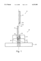
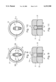
- FIG. 1 is a sectional view of a punch and die set of one embodiment of the present invention, illustrating the punch in the down position on the left side and in the up position on the right side;
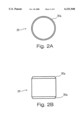
- FIG. 2A is a front view of a workpiece which can be formed into an automotive rocker arm as illustrated by FIGS. 10-14 if inserted into the embodiment of this invention illustrated in FIGS. 1 and 3-9 and the embodiment completes a forging cycle;
- FIG. 2B is a top view of the workpiece illustrated in FIG. 2A;
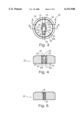
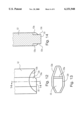
- FIG. 3 is a top view of a lower die of one embodiment of this invention.
- FIG. 4 is a cross-sectional view along line 4--4 of FIG. 3;
- FIG. 5 is a cross-sectional view along line 5--5 of FIG. 3;
- FIG. 6 is a side view of the outer die segment of the embodiment illustrated in FIG. 3;
- FIG. 7 is a side view of the center die segment of the embodiment illustrated in FIG. 3;
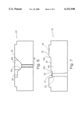
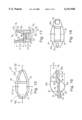
- FIG. 8 is a top view of an assembled die set of one embodiment of this invention.
- FIG. 9 is a cross-sectional view along line 9--9 of FIG. 8, showing an upper die positioned on top of a lower die;
- FIG. 10 is a top view of the assembled die set of FIG. 8 with a workpiece positioned therein;
- FIG. 11 is a cross-sectional view along line 11--11 of FIG. 10;
- FIG. 12 is a side view of a punch of one embodiment of this invention.
- FIG. 13 is a bottom view of the punch of FIG. 12;
- FIG. 14 is a cross-sectional view along line 14--14 of FIG. 12;
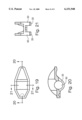
- FIG. 15 is a top view of an as-forged rocker arm which can be produced using the die set of FIGS. 1 and 3-11 and the punch of FIGS. 1 and 12-14;
- FIG. 16 is a cross-sectional view along line 16--16 of FIG. 15;
- FIG. 17 is a cross-sectional view along line 17--17 of FIG. 15;
- FIG. 18 is a bottom view of the rocker arm shown in FIGS. 15-17;
- FIG. 19 is a top view of a finished rocker arm which can be produced using the die set of FIGS. 1 and 3-11, the punch of FIGS. 1 and 12-14, and a known boring apparatus;
- FIG. 20 is a cross-sectional view along line 20--20 of FIG. 19.
- FIG. 21 is a cross-sectional view along line 21--21 of FIG. 19.
- This invention is directed to punch and die combinations that can be used in conventional forging presses to produce relatively small, complex shaped metal parts, such as automotive rocker arms, by near net warm forging. This invention also provides methods of using these combinations to form the desired metal parts.
- FIG. 1 illustrates one embodiment of this invention, a forging apparatus 10 comprising a forging punch 12 that is reciprocatable into and away from a die set 20.
- the left side of FIG. 1 shows the punch 12 in the down position with respect to the die set 20, while the right side of FIG. 1 shows the punch 12 in the up position.
- the punch and die form a closed die cavity.
- a workpiece 30, shown in the right side of the figure, is forged into a rocker arm 30' within the die cavity, as shown in the left side of the figure, by forging apparatus 10.
- the punch and die combinations of this invention can be used to warm forge metal parts.
- warm forging processes utilizing these combinations are conducted at a temperature range of from about 1200° F. to about 2200° F.
- the optimum warm forging temperature range to produce a given part is dependent on various factors, including the workpiece material and shape, the part configuration, the configuration and composition of the die cavity, etc.
- the automotive rocker arm 30' has been warm forged, using the punch 12, the die set 20 and a workpiece 30 (see FIGS. 2A and 2B) of 1018 or 1050 steel, at a temperature range of from about 1800° F. to about 1900° F.
- FIGS. 15-18 illustrate the automotive rocker arm, rocker arm 30', that is produced by forging apparatus 10.
- the rocker arm 30' is symmetrical about a longitudinal plane 16--16 and includes a base member 31, top side members 32, and bottom side members 33.
- the top side members 32 extend upwardly from the base member 31 and the bottom side members 33 extend downwardly from the base member 31.
- the base member 31 includes a hemispherical concave recess 34, a top surface 35, a contact pad 36, a bottom surface 38, and transition portions 35a, 38a and 38b, and is tapered inwardly at each end thereof (when viewed from the top). See FIGS. 15 and 16.
- the hemispherical concave recess 34 is provided at one end of the bottom surface 38 for receiving and engaging an end of a push rod (not shown).
- the contact pad 36 is provided at another end of the bottom surface 38 for contacting an end of a valve stem (not shown).
- the contact pad 36 may be of any desired shape and thickness. In this embodiment of the invention, the contact pad 36 is slightly curved when viewed from the side (see FIG. 16). In some embodiments of this invention, the contact pad 36 can be omitted, i.e., in some embodiments the rocker arm will not include a contact pad.
- the base member 31 has a stepped planar configuration when viewed from the side (see FIG. 16), with the transition portion 35a between different elevations of the top surface 35 of the base member 31, and transition portions 38a and 38b between different elevations of the bottom surface 38.
- the base member 31 may have a completely planar configuration or a slightly curved configuration, or any other desired configuration (when viewed from the side).
- the configuration of the base member 31 is designed such that (1) the hemispherical concave recess 34 engages the push rod and the contact pad 36 engages the valve stem of the cylinder head with which the rocker arm 30' is to be used and (2) the mass of rocker arm 30' is as optimally distributed as possible. It is preferable for the base member 31 to be as thin as practically possible, because the thickness of the base member 31 does not add significantly to the rigidity of the rocker arm 30'.
- top side members 32 extend upwardly from the top of the base member 31. See FIGS. 16 and 17.
- the top side members 32 extend substantially the length of the base member 31 and are defined by top edge surfaces 32a (which are continuously curved and taper to a height of zero near the respective ends of the base member 31 in this embodiment), outer side surfaces 32b and top inner side surfaces 32c.
- the top side members 32 angle in toward the longitudinal center plane of the rocker arm 30', following the tapers of the base member 31.
- the top side members 32 have a maximum height h 1max and a thickness t 1 .
- bottom side members 33 extend downwardly from the bottom of the base member 31. See FIGS. 16 and 17.
- the bottom side members 33 are defined by bottom edge surfaces 33a (which are continuously curved and taper to a height of zero at their respective ends in this embodiment), outer side surfaces 32b and bottom inner side surfaces 33c.
- the bottom side members 33 have a maximum height h 2max and a thickness t 2 .
- top side members 32 and the bottom side members 33 of this embodiment are continuously curved, this invention is not limited to top and bottom side members having this configuration. Rather, the top and bottom side members may be of any feasible configuration (when viewed from the side).
- the members 32 and/or 33 may be rectangular, having a constant height, stepped in a staircase configuration, or formed by a series of straight and/or curved line segments, as desired.
- the tapered configuration of the embodiment illustrated in the Figures is generally considered to be advantageous for automotive rocker arms, as it provides rigidity and strength to the rocker arms without having excess material at the ends of the rocker arms. This design reduces the moment created when the rocker arms rock back and forth, thereby avoiding unnecessary diminishing of the available horsepower of an engine.
- Top inner side surfaces 32c of the top side members 32 and bottom inner side surfaces 33c of the bottom side members 33 are substantially parallel to outer side surfaces 32b of the rocker arm 30'. Stated differently, surfaces 32b, 32c and 33c have very small draft angles, if any.
- the surface transitions between (1) the top edge surfaces 32a and the outer side surfaces 32b and (2) the bottom edge surfaces 33a and the bottom inner side surfaces 33c may have extremely small radii r 1 and r 2 , respectively (see FIG. 17).
- the radii r 1 and r 2 may be on the order of about 0 to about 1 mm, where a radius of 0 indicates a substantially right-angle transition.
- top surface 35 of base member 31 and top inner side surfaces 32c, (2) the bottom surface 38 and bottom inner side surfaces 33c, (3) the top inner side surfaces 32c and the top edge surfaces 32a and (4) the bottom edge surfaces 33a and the outer side surfaces 32b may have radii R 1 , R 2 , R 3 and R 4 , respectively, on the order of about 1 mm to about 2 mm.
- the top side members 32 and the bottom side members 33 of the rocker arm 30' have relatively small widths t 1 and t 2 compared to their maximum heights h 1max and h 2max , respectively, as shown in FIGS. 11 and 12.
- This invention has particular utility in the warm forging of parts having members which extend from a central portion a distance greater than the width of the member.
- the top side members 32 have a width-to-maximum height ratio of about 1:6 and the bottom side members 33 have a width-to-maximum height ratio of about 1:1.5.
- Parts having top and/or bottom members having width-to-maximum height ratios of lower than 1:6, such as 1:10, can also be effectively and efficiently produced by methods and apparatuses according to this invention.
- This invention encompasses any such ratio that may be achieved using the methods and apparatuses of this invention.
- the die set 20 will next be described, with reference to FIGS. 1 and 3-11.
- the die set 20 comprises an upper die 21, a lower die 22 and a base 50.
- the upper die 21 may be nested on and secured to the lower die 22 by a conventional retaining mechanism (not shown).
- the nested dies may be placed on and secured to the base 50 (see FIG. 1).
- the lower die 22 includes two outer die segments 24 and a center die segment 25.
- the two outer die segments 24 are mirror images of each other, and are positioned on opposite sides of the center die segment 25.
- the outer die segments 24 have cavity-defining surfaces 28', 42b and 43a. See FIGS. 3 and 6. Surfaces 28' each correspond to a portion of the bottom surface 38 of the rocker arm 30'. Surfaces 42b correspond to the lower portions of outer side surfaces 32b of the rocker arm 30'. Surfaces 43a correspond to bottom edge surfaces 33a of the rocker arm 30'.
- the outer die segments 24 also have vertical holes 42 (see FIG. 4) formed therein which are sized and shaped to slidingly accommodate the ejector pins 40 (discussed below).
- the ejector pins 40 are reciprocatable within the holes 42 in the outer die segment 24. As illustrated in FIG. 6, the top surfaces of the ejector pins 40 of this embodiment respectively form portions of cavity-defining surfaces 43a when the pins 40 are in a retracted position. In other words, the top surfaces of the ejector pins 40 are aligned with cavity-defining surfaces 43a when the ejector pins 40 are in a retracted, or non-actuated, position. In other embodiments, the ejector pins may be located such that their top surfaces form portions of other cavity-defining surfaces. For example, at least one ejector pin may be located such that its top surface forms a portion of the top surface 28 of the center die segment 25 (discussed below).
- the rocker arm 30' is ejected from the die set 20 by ejector pins 40.
- the ejector pins 40 may be actuated automatically or manually by any suitable mechanism.
- the center die segment 25 has a pin 27, a vertical bore 29, a concave indented portion 26, a top surface 28, and side surfaces 43c. See FIGS. 3 and 7.
- the top surface 28 corresponds in shape to the shape of the bottom surface 38 of the rocker arm 30' (see FIGS. 11 and 13).
- the pin 27 is positioned within the vertical bore 29 (see FIG. 5).
- the distal end of the pin 27 is dome-shaped, having a shape that corresponds to the desired shape of the hemispherical concave recess 34 of the rocker arm 30'.
- the concave indented portion 26 corresponds in shape and position to the desired shape and position of the contact pad 36 of the rocker arm 30'.
- Portions 28a and 28b of the surface 28 of die segment 25 correspond in shape and position to transition portions 38a and 38b, respectively, of the bottom surface 38 of the rocker arm 30'.
- Side surfaces 43c of center die segment 25 correspond to bottom inner side surfaces 33c of bottom side members 33.
- the cavity-defining surfaces 42b and 43a of the outer side segments 24 and the side surfaces 42c of the center die segment 25 define cavity portions 23.
- the cavity portions 23 correspond in shape and size to the shape and size of the bottom side members 33 of the rocker arm 30'.
- cavity-defining surfaces 28' of the outer die segments 24 are substantially coplanar with respective portions of the top surface 28 of the center die segment 25 (see FIGS. 3 and 6-7).
- the assembled lower die 22 has a substantially circular perimeter when viewed from the top, as in FIG. 3. Because of the segmented configuration in which the two outer die segments 24 are positioned on opposite sides of the center die segment 25, the outer die segments 24 can be machined from a single piece of circular stock material. Specifically, when a cylindrical piece of stock material is divided, a saw kerf or the like is formed that takes away material from between the two resulting halves of the stock material. If these two "halves" are put back together, the resulting shape is no longer circular in cross section due to the reduced material in the center.
- center die segment 25 when a third segment, such as center die segment 25, is positioned between the "halves", the center segment 25 essentially compensates for the saw kerf, and the "halves" no longer need to be perfectly semi-circular to form a circle in cross section.
- the desired circular cross section can be achieved by combining the center die segment 25 with the outer die segments 24. Therefore, the material used to form the dies is efficiently utilized.
- the upper die 21 is placed on top of the lower die 22, and the two dies are secured together in a known manner.
- the upper die 21 has a cut-out 21a that is the shape of the perimeter of rocker arm 30' (when viewed from the top) and includes surfaces 21b that correspond to the upper portion of outer side surfaces 32b of the rocker arm 30'.
- the surfaces 21b of the upper die 21 are substantially coplanar with the surfaces 42b of the lower die 22 when dies 21 and 22 are assembled.
- Punch 12 includes forming surfaces 12a, 12c, 15 and 15a.
- Forming surfaces 12a correspond in shape and size to the shape and size of top edge surfaces 32a of top side members 32 of the rocker arm 30' (see FIGS. 11-12).
- Forming surfaces 12c correspond in shape and size to the shape and size of top inner side surfaces 32c of the rocker arm 30'.
- Forming surface 15 corresponds in shape and size to the shape and size of top surface 35 of the rocker arm 30'.
- Forming surface 15a corresponds in shape and size to the shape and size of the transition portion 35a of the top surface 35 of the rocker arm 30'.
- FIGS. 2A and 2B A workpiece which can be inserted in forging apparatus 10 to produce rocker arm 30', workpiece 30, is illustrated in FIGS. 2A and 2B.
- the workpiece 30 is generally cylindrically shaped, having a length-to-diameter ratio in a range of from about 1:0.5 to about 1:1.5, and preferably, of approximately 1:1.
- rocker arm 30' can be more effectively and efficiently produced from a workpiece having a centralized mass, such as workpiece 30, for the following reason.
- all distal surfaces of the die cavity including the end surfaces of any relatively long, narrow portions of the cavity, are contacted by the workpiece material at substantially the same time during the forging stroke. This prevents rollover and other forging phenomena from occurring which may cause imperfections in the finished parts.
- a die cavity has centralized elongated portions, such as the die cavity in die set 20, the use of a workpiece having a centralized mass results in the workpiece material reaching the distal surfaces of all of the cavity portions substantially simultaneously.
- the workpieces may also be of other shapes having a large mass near the center portion, such as a generally cubic shape or a generally spherical shape.
- axi-symmetrical workpieces such as cylindrical workpieces, may be the optimally shaped workpieces to effectively and efficiently produce the desired part configuration.
- the volume of the workpiece 30 is substantially equal to the volume of the as-forged rocker arm 30'. This is accomplished by selecting a workpiece having the appropriate height and diameter.
- the volume of the workpiece may be optimized by adjustment of the geometry at the design stage. For example, as shown in FIGS. 2A and 2B, an optimized volume is achieved with formed bevel surfaces 30a on the ends of the workpiece 30.
- a rocker arm 30' is produced from a workpiece 30 utilizing forging apparatus 10, as follows.
- the workpiece 30 is heated to the desired temperature range, lubricated (if desired or necessary) and inserted into the cavity of die set 20.
- the longitudinal axis of the workpiece 30 is aligned with the longitudinal axis of the die set. See FIG. 8.
- the workpiece 30 may be placed at any other orientation, such as with its longitudinal axis aligned with a lateral axis or a vertical axis of the die set.
- the punch 12 then conducts a forging stroke, impacting and deforming the workpiece 30 into the configuration defined by the die cavity walls and forming surfaces of the punch 12, which is the configuration of the rocker arm 30'.
- the punch 12 is lowered to its lowermost position, as illustrated on the left side of FIG. 1.
- a die cavity is formed by the punch and die surfaces described above.
- the workpiece material completely fills the die cavity, flowing in the upward, downward, and lateral directions.
- workpiece material fills the die cavity such that the cavity surfaces located the furthest from the center of the cavity are contacted by workpiece material at substantially the same time.
- the workpiece material flows downward and laterally to fill the cavity portions 23 defined by cavity-defining surfaces 43a and side surfaces 42b of outer die segments 24 and side walls 43c of center die segment 25, upward and laterally to fill the cavity portions defined by forming surfaces 12a and 12c of punch 12 and surfaces 21b of upper die 21, and laterally to fill the cavity portions between surface 28 of center die segment 25 and forming surface 15 of punch 12.
- the pin 27 (see FIG. 5) is located in a fixed position within the bore 29 to form the concave recess 34 in the bottom surface 38 of the rocker arm 30'.
- the pin 27 is fixed at the appropriate forming depth by the base 50, which sits below the pin 27.
- the punch 12 is then retracted into its raised position and the ejector pins 40 are actuated, forcing the as-forged rocker arm 30' out of the die cavity.
- the as-forged rocker arm 30' has the above-described configuration.
- the as-forged parts may have very small amounts of flash which may be easily removed by, for example, placing a plurality of as-forged parts in a tumbling machine and tumbling them until the desired smoothness is achieved.
- the as-forged rocker arms 30' can be further processed if desired or necessary to produce finished rocker arms.
- holes 60 may be bored in the bottom side members 33 for receiving a member (not shown) that attaches the rocker arms 30' to the cylinder head of an engine.
- the concave recess 34 and/or the contact pad 36 may be subjected to final processing, such as finish grinding or polishing.
- final processing such as finish grinding or polishing.
- the methods and apparatuses of this invention can efficiently produce complex-shaped parts, such as forged rocker arms 30', by near net warm forging.
- This invention is particularly useful in producing parts having members with relatively large heights or other elongated portions because of the features described above.
- the methods and apparatuses of this invention allow adequate flow of the workpiece material in all directions, including the upward direction, so that the flowing workpiece material properly fills the entire die cavity (including relatively elongated, narrow spaces) and contacts all of the distal cavity surfaces at substantially the same time.
- segmented lower die set allows mating dies to have finely machined surfaces and sharp corners, thereby allowing the as-forged parts to have small radii at surface transitions, and parallel inner and outer side surfaces. Unlike other forging processes and methods, substantially no draft angles are required to facilitate removal of the as-forged parts from the die set. Therefore, workpiece material is efficiently utilized.
Landscapes
- Engineering & Computer Science (AREA)
- Mechanical Engineering (AREA)
- General Engineering & Computer Science (AREA)
- Forging (AREA)
Abstract
Description
Claims (52)
Priority Applications (1)
| Application Number | Priority Date | Filing Date | Title |
|---|---|---|---|
| US09/257,919 US6151948A (en) | 1999-02-26 | 1999-02-26 | Methods and apparatuses for producing complex-shaped metal parts by forging |
Applications Claiming Priority (1)
| Application Number | Priority Date | Filing Date | Title |
|---|---|---|---|
| US09/257,919 US6151948A (en) | 1999-02-26 | 1999-02-26 | Methods and apparatuses for producing complex-shaped metal parts by forging |
Publications (1)
| Publication Number | Publication Date |
|---|---|
| US6151948A true US6151948A (en) | 2000-11-28 |
Family
ID=22978355
Family Applications (1)
| Application Number | Title | Priority Date | Filing Date |
|---|---|---|---|
| US09/257,919 Expired - Lifetime US6151948A (en) | 1999-02-26 | 1999-02-26 | Methods and apparatuses for producing complex-shaped metal parts by forging |
Country Status (1)
| Country | Link |
|---|---|
| US (1) | US6151948A (en) |
Cited By (15)
| Publication number | Priority date | Publication date | Assignee | Title |
|---|---|---|---|---|
| US6401765B1 (en) * | 2000-08-22 | 2002-06-11 | Texas Instruments Incorporated | Lead frame tooling design for exposed pad features |
| WO2002078875A1 (en) * | 2001-03-29 | 2002-10-10 | Showa Denko K.K. | Closed forging metod, forging production system using the method, forging die used in the method and system, and preform or yoke produced by the method and system |
| EP1348501A1 (en) * | 2002-03-29 | 2003-10-01 | Peugeot Citroen Automobiles SA | Method for the manufacture of a forged connecting rod and tool for carrying out the method |
| FR2837730A1 (en) * | 2002-03-29 | 2003-10-03 | Peugeot Citroen Automobiles Sa | Forged connecting rod manufacturing procedure starts with cylindrical metal slug that is formed into a pre-blank and shaped between matrices |
| US6742253B2 (en) | 2001-06-29 | 2004-06-01 | Gkn Sinter Metals | Process for eliminating vertical flash on an as-forged connecting rod |
| WO2004073903A1 (en) * | 2003-02-18 | 2004-09-02 | Showa Denko K.K. | Metal forged product upper or lower arm preform of the arm production method for the metal forged product forging die and metal forged product production system |
| US20060273542A1 (en) * | 2003-06-11 | 2006-12-07 | Chamberlain Jason L | Head tube for bicycle frame |
| US20070000297A1 (en) * | 2005-07-04 | 2007-01-04 | Otics Corporation | Method of manufacturing rocker arm |
| CN1298455C (en) * | 2001-03-29 | 2007-02-07 | 昭和电工株式会社 | Closed forging method, forging prodn. system using method, forging die used in method and system, and preform or yoke produced by method and system |
| US20070157693A1 (en) * | 2006-01-10 | 2007-07-12 | Gkn Sinter Metals, Inc. | Forging/coining method |
| EP1927413A1 (en) * | 2006-12-01 | 2008-06-04 | Topy Kogyo Kabushiki Kaisha | Press forging method |
| CN101190453B (en) * | 2006-12-01 | 2011-07-06 | 都美工业株式会社 | Press forging method |
| US8167327B2 (en) | 2010-05-14 | 2012-05-01 | Specialized Bicycle Components, Inc. | Bicycle frame |
| CN104722632A (en) * | 2013-12-24 | 2015-06-24 | 黄品贵 | Method for manufacturing stainless steel handle cores |
| USD958702S1 (en) | 2020-08-05 | 2022-07-26 | Specialized Bicycle Components, Inc. | Bicycle frame |
Citations (5)
| Publication number | Priority date | Publication date | Assignee | Title |
|---|---|---|---|---|
| US2814101A (en) * | 1953-04-14 | 1957-11-26 | Prex Forgings Corp | Forging die and method |
| US3691804A (en) * | 1971-01-26 | 1972-09-19 | Metal Forming And Coining Corp | Cold extruded article and method of making the same |
| US4222260A (en) * | 1978-05-15 | 1980-09-16 | Wsp Industries Corporation | Warm forging of connecting rod caps |
| US4377085A (en) * | 1980-04-16 | 1983-03-22 | W-F Industries, Inc. | Female dies and method of manufacture |
| US4426872A (en) * | 1981-09-30 | 1984-01-24 | W-F Industries, Inc. | Die set and billet for use therein |
-
1999
- 1999-02-26 US US09/257,919 patent/US6151948A/en not_active Expired - Lifetime
Patent Citations (5)
| Publication number | Priority date | Publication date | Assignee | Title |
|---|---|---|---|---|
| US2814101A (en) * | 1953-04-14 | 1957-11-26 | Prex Forgings Corp | Forging die and method |
| US3691804A (en) * | 1971-01-26 | 1972-09-19 | Metal Forming And Coining Corp | Cold extruded article and method of making the same |
| US4222260A (en) * | 1978-05-15 | 1980-09-16 | Wsp Industries Corporation | Warm forging of connecting rod caps |
| US4377085A (en) * | 1980-04-16 | 1983-03-22 | W-F Industries, Inc. | Female dies and method of manufacture |
| US4426872A (en) * | 1981-09-30 | 1984-01-24 | W-F Industries, Inc. | Die set and billet for use therein |
Non-Patent Citations (4)
| Title |
|---|
| "Jeg's" Catalog, vol. K, Feb. 1998, p. 67-K. |
| "Summit racing Equipment" Catalog, Feb. 1998, pp. 43-45. |
| Jeg s Catalog, vol. K, Feb. 1998, p. 67 K. * |
| Summit racing Equipment Catalog, Feb. 1998, pp. 43 45. * |
Cited By (27)
| Publication number | Priority date | Publication date | Assignee | Title |
|---|---|---|---|---|
| US6401765B1 (en) * | 2000-08-22 | 2002-06-11 | Texas Instruments Incorporated | Lead frame tooling design for exposed pad features |
| US20040093926A1 (en) * | 2001-03-29 | 2004-05-20 | Masayuki Natsui | Closed forging metod, forging production system using the method, forging die used in the method and system, and preform or yoke produced by the method and system |
| WO2002078875A1 (en) * | 2001-03-29 | 2002-10-10 | Showa Denko K.K. | Closed forging metod, forging production system using the method, forging die used in the method and system, and preform or yoke produced by the method and system |
| CN1298455C (en) * | 2001-03-29 | 2007-02-07 | 昭和电工株式会社 | Closed forging method, forging prodn. system using method, forging die used in method and system, and preform or yoke produced by method and system |
| US7257981B2 (en) | 2001-03-29 | 2007-08-21 | Showa Denko K.K. | Closed forging method, forging production system using the method, forging die used in the method and system, and preform or yoke produced by the method and system |
| US6742253B2 (en) | 2001-06-29 | 2004-06-01 | Gkn Sinter Metals | Process for eliminating vertical flash on an as-forged connecting rod |
| FR2837731A1 (en) * | 2002-03-29 | 2003-10-03 | Peugeot Citroen Automobiles Sa | METHOD FOR MANUFACTURING A FORGED CONNECTING ROD AND TOOLS FOR IMPLEMENTING THIS METHOD |
| EP1350584A2 (en) * | 2002-03-29 | 2003-10-08 | Peugeot Citroen Automobiles SA | Method and tool for forming a forged connecting rod |
| EP1350584A3 (en) * | 2002-03-29 | 2004-08-04 | Peugeot Citroen Automobiles SA | Method and tool for forming a forged connecting rod |
| FR2837730A1 (en) * | 2002-03-29 | 2003-10-03 | Peugeot Citroen Automobiles Sa | Forged connecting rod manufacturing procedure starts with cylindrical metal slug that is formed into a pre-blank and shaped between matrices |
| EP1348501A1 (en) * | 2002-03-29 | 2003-10-01 | Peugeot Citroen Automobiles SA | Method for the manufacture of a forged connecting rod and tool for carrying out the method |
| WO2004073903A1 (en) * | 2003-02-18 | 2004-09-02 | Showa Denko K.K. | Metal forged product upper or lower arm preform of the arm production method for the metal forged product forging die and metal forged product production system |
| US20060185416A1 (en) * | 2003-02-18 | 2006-08-24 | Takafumi Nakahara | Metal forged product, upper or lower arm, preform of the arm, production method for the metal forged product, forging die, and metal forged product production system |
| US7770427B2 (en) | 2003-02-18 | 2010-08-10 | Showa Denko K.K. | Metal forged product, upper or lower arm, preform of the arm, production method for the metal forged product, forging die, and metal forged product production system |
| US20060273542A1 (en) * | 2003-06-11 | 2006-12-07 | Chamberlain Jason L | Head tube for bicycle frame |
| US7506528B2 (en) * | 2003-06-11 | 2009-03-24 | Specialized Bicycle Components, Inc. | Head tube for bicycle frame |
| US20070000297A1 (en) * | 2005-07-04 | 2007-01-04 | Otics Corporation | Method of manufacturing rocker arm |
| US7360290B2 (en) | 2005-07-04 | 2008-04-22 | Otics Corporation | Method of manufacturing rocker arm |
| EP1741503A1 (en) * | 2005-07-04 | 2007-01-10 | OTICS Corporation | Method of manufacturing a rocker arm |
| US20070157693A1 (en) * | 2006-01-10 | 2007-07-12 | Gkn Sinter Metals, Inc. | Forging/coining method |
| EP1927413A1 (en) * | 2006-12-01 | 2008-06-04 | Topy Kogyo Kabushiki Kaisha | Press forging method |
| US20080141752A1 (en) * | 2006-12-01 | 2008-06-19 | Toshihiko Sato | Press forging method |
| CN101190453B (en) * | 2006-12-01 | 2011-07-06 | 都美工业株式会社 | Press forging method |
| US8047042B2 (en) | 2006-12-01 | 2011-11-01 | Topy Kogyo Kabushiki Kaisha | Press forging method |
| US8167327B2 (en) | 2010-05-14 | 2012-05-01 | Specialized Bicycle Components, Inc. | Bicycle frame |
| CN104722632A (en) * | 2013-12-24 | 2015-06-24 | 黄品贵 | Method for manufacturing stainless steel handle cores |
| USD958702S1 (en) | 2020-08-05 | 2022-07-26 | Specialized Bicycle Components, Inc. | Bicycle frame |
Similar Documents
| Publication | Publication Date | Title |
|---|---|---|
| US6151948A (en) | Methods and apparatuses for producing complex-shaped metal parts by forging | |
| CN108580778B (en) | Forging method of thin-wall deep-cavity airplane hub die forging | |
| US5054195A (en) | Process for the production of a valve | |
| CN102076964B (en) | Die for forging rotor material and method for forging rotor material | |
| US7578229B2 (en) | Piston produced from a single forged or cast piston blank | |
| US2392175A (en) | Process of making hollow valves | |
| CN112059091B (en) | Disc type aluminum alloy automobile hub forging die structure and forging method | |
| US5878491A (en) | Process for the manufacture of a forged connecting rod | |
| JP2003285138A (en) | Method for manufacturing cam piece for built-up cam shaft | |
| JP2010142877A (en) | Method of forming member having undercut part | |
| US2024285A (en) | Method of making pistons | |
| KR101003252B1 (en) | Die device of closed-die forging for crank throw pin part using insert die | |
| CN104942200B (en) | I-shaped joint rotating die and forming process thereof | |
| CN113857404A (en) | Method for forging hinge beam in short process | |
| US7213337B1 (en) | Method of manufacturing pistons and components thereof, and forging tools | |
| US3010186A (en) | Piston manufacture | |
| CN113245491B (en) | Crank die forging combined female die | |
| US7104109B2 (en) | Double-cavity heading die | |
| CN107520390A (en) | Double floating type lock ring cold closed-die forging one step forming mould | |
| CN211638189U (en) | Manufacturing die set of 2014 aluminum alloy aviation precision hub die forging | |
| CN211758289U (en) | Magnesium-aluminum alloy wheel forward and backward forging device | |
| RU2332276C1 (en) | Method of making ring shaped component parts | |
| US5941651A (en) | Process for the fabrication of parts made of cast alloys with reinforcement zones | |
| KR102517694B1 (en) | Method for manufacturing Aluminium long bush for electric vehicle battery | |
| JP5053800B2 (en) | Manufacturing method of oblique bottomed cylindrical member |
Legal Events
| Date | Code | Title | Description |
|---|---|---|---|
| AS | Assignment |
Owner name: MSP INDUSTRIES CORPORATION, MICHIGAN Free format text: ASSIGNMENT OF ASSIGNORS INTEREST;ASSIGNORS:ASHWORTH, MARTIN J.;WEBSTER, JAMES;DANCOE, JOHN P.;REEL/FRAME:009799/0209 Effective date: 19990226 |
|
| STCF | Information on status: patent grant |
Free format text: PATENTED CASE |
|
| AS | Assignment |
Owner name: CHASE MANHATTAN BANK, AS COLLATERAL AGENT, THE, NE Free format text: SUPPLEMENT TO INTELLECTUAL PROPERTY SECURITY AGREE;ASSIGNORS:AMERICAN AXLE & MANUFACTURING, INC.;MSP INDUSTRIES CORPORATION;COLFOR MANUFACTURING, INC.;REEL/FRAME:012177/0112 Effective date: 20010815 |
|
| AS | Assignment |
Owner name: AMERICAN AXLE & MANUFACTURING, INC., MICHIGAN Free format text: SECURITY AGREEMENT RELEASE;ASSIGNOR:JPMORGAN CHASE BANK;REEL/FRAME:014926/0190 Effective date: 20040116 |
|
| FPAY | Fee payment |
Year of fee payment: 4 |
|
| FPAY | Fee payment |
Year of fee payment: 8 |
|
| FPAY | Fee payment |
Year of fee payment: 12 |
|
| AS | Assignment |
Owner name: JPMORGAN CHASE BANK, N.A., AS COLLATERAL AGENT, NE Free format text: SECURITY INTEREST;ASSIGNORS:AMERICAN AXLE & MANUFACTURING, INC.;CLOYES GEAR AND PRODUCTS, INC.;GREDE LLC;AND OTHERS;REEL/FRAME:042734/0001 Effective date: 20170605 Owner name: JPMORGAN CHASE BANK, N.A., AS COLLATERAL AGENT, NEW YORK Free format text: SECURITY INTEREST;ASSIGNORS:AMERICAN AXLE & MANUFACTURING, INC.;CLOYES GEAR AND PRODUCTS, INC.;GREDE LLC;AND OTHERS;REEL/FRAME:042734/0001 Effective date: 20170605 |