EP1741402B1 - Vorrichtung wie eine chirurgische Vorrichtung - Google Patents
Vorrichtung wie eine chirurgische Vorrichtung Download PDFInfo
- Publication number
- EP1741402B1 EP1741402B1 EP06291092A EP06291092A EP1741402B1 EP 1741402 B1 EP1741402 B1 EP 1741402B1 EP 06291092 A EP06291092 A EP 06291092A EP 06291092 A EP06291092 A EP 06291092A EP 1741402 B1 EP1741402 B1 EP 1741402B1
- Authority
- EP
- European Patent Office
- Prior art keywords
- instrument
- instruments
- insert
- rays
- conveyor
- Prior art date
- Legal status (The legal status is an assumption and is not a legal conclusion. Google has not performed a legal analysis and makes no representation as to the accuracy of the status listed.)
- Not-in-force
Links
Images


Classifications
-
- A—HUMAN NECESSITIES
- A61—MEDICAL OR VETERINARY SCIENCE; HYGIENE
- A61B—DIAGNOSIS; SURGERY; IDENTIFICATION
- A61B90/00—Instruments, implements or accessories specially adapted for surgery or diagnosis and not covered by any of the groups A61B1/00 - A61B50/00, e.g. for luxation treatment or for protecting wound edges
- A61B90/90—Identification means for patients or instruments, e.g. tags
Definitions
- An instrument such as a surgical instrument of a predetermined type, defined by its shape and function, among a plurality of instruments of different types.
- the document DE 100 14 542 describes a surgical instrument that includes a transmitter of a radio frequency signal, representative of the identification code of the instrument, which makes it possible to check whether an instrument could have been forgotten in the surgical intervention wound, before closing of it.
- the document US 5782764 a A medical instrument that is designed to be used in an imaging system for medical diagnostic purposes, that is, to visualize the presence of the instrument on an image representing tissues of a part of the body. a body of a patient.
- the document GB 2409445 describes a surgical instrument that is identifiable by colored marks provided on this instrument.
- Surgical instruments according to the state of the art prove to be complex or insufficient for a reliable identification of the instruments.
- the invention aims to overcome these disadvantages.
- the invention comprises the features which are set forth in the characterizing part of claim 1.
- the advantage of the invention lies in the fact that the instruments of the invention allow a recognition of their type, using X-rays, automatically, they are described below in the context a method and an automatic sorting facility for surgical instruments.
- the description is only given by way of example, but, in general, the invention is usable for any operation that involves a selection and storage of specific instruments for the implementation of the operation.
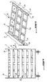
- an installation for sorting the instruments necessary for a surgical operation, essentially comprises, arranged inside a chamber with a white environment 1, that is to say a most perfect cleanliness possible, essentially a storage device for all the surgical instruments that can be used for the various possible surgical operations, in the clean state, a device 3 for transferring the instruments to a conveyor 4 intended to transport them to a station 5 of recognition of the nature or type of the instruments and a mechanism for storing the instruments after their recognition in containers 7 each of which is intended to contain the instruments to be used for a predetermined operation, a container 8 being provided for the receipt of instruments deemed not to conform to the requirements established for surgical operations.
- the device 2 for storing the set of instruments is made, in the case of example, in the form of a carriage comprising a number of levels 9 of each retaining a plurality of trays 10, in the example shown 3, each of which may comprise a plurality of cells 12 for housing a surgical instrument 14. In this case, for the sake of simplification of the drawings, each plate has only one cell.
- the trays 10 of each level 9 of the storage trolley 2 are supported by support members in the form of a sliding rail 16 each fixed to a side wall 17 of the trolley oriented in the direction of the conveyor 4.
- each plate 10 consists of two superimposed frames made of an easily cleanable material, such as stainless steel, namely a lower frame element 19 of generally rectangular shape and an upper frame 20 of complementary shape and capable of to be fixed on the lower frame, by means in the form of clips (not shown), capable of clamping the upper frame on the lower frame for a replaceable element 21, advantageously disposable, a flexible material transparent to X-rays such as paper or fabric, can be inserted at two of its opposite edges between the corresponding edges of the two frames, to form a cell 12 for housing an instrument 14 and thus the bottom of the tray.
- the lower frame 19 is provided with support members 23 in the form of arches, at each longitudinal end. It is advantageous for the cell to be closed at each longitudinal end by a vertical wall 24 forming the space between the frame and the corresponding arc 23.
- each plate 10 is movable in the carriage 2, perpendicular to its longitudinal axis, supported by the short sides 25 on the sliding rails 16 of the carriage.
- the transfer arrangement of the trays 10 of each stage of the carriage comprises, to push the trays out of the carriage, a push device 27 and mounted vertically movable to the rear of the carriage 2, to be positionable at each level 9 of the carriage.
- the device comprises a pusher piston of a hydraulic cylinder which, during its output movement, pushes the last plate and thus moves the set of trays towards the conveyor.
- the transfer device 3 further comprises, at the front of the storage trolley 2 of trays 10 a frame 30 for transferring the trays 10 of the carriage 2 to the conveyor 4, which is vertically displaceable so as to receive the trays of each level 9 of storage of the carriage and then to transport them to the height of the conveyor 4 so that the trays can be placed on the latter.
- the transfer frame essentially comprises two sliding rails 31, each being capable of being aligned, in a tray receiving position of a level or stage 9, to a sliding rail 16 level, so that the trays 10 can be moved, under the effect of the pusher device 27 of the rails 16 of the carriage to the rails 31 of the transfer frame 30.
- the transfer frame is sized to successively transfer the trays 10 to conveyor 4.
- the conveyor 4 is shown on the figure 1 , as being produced in the form of an endless conveyor belt comprising, essentially two parallel flat strands 33, intended for the transport of the trays 10, connected by crosspieces 34.
- the rails of support 31 of the transfer frame extend to above the conveyor and its tray support portion, in its forward transfer position, is lowered to allow the installation of the carriages on the conveyor strands located below. Then they deviate laterally and return to their position of receiving a new plateau.
- the conveyor 4 transports the trays received from the storage trolley 2, via the transfer frame 3 to the recognition station 5 of the instruments placed in the cells 12 of the trays 10.
- the figure 2 shows by way of example, a surgical clip in one of the branches denoted 36 of which is incorporated an insert 35.
- the instrument recognition station is advantageously an X-ray reader, in the form of a gantry, through which the conveyor 4 passes and which comprises, disposed above the conveyor 4, an X-ray source 37, while a ray receiver having passed through the instrument 14 is disposed under the conveyor.
- the elements of the latter which constitute the identification code, must be less transparent to X-rays than the constituent material of the instrument.
- This code could reside for example in the form of the insert or marks provided on it or the shape or location of a notch made in the insert. Inserts of this kind being known per se, it is not necessary to describe it in more detail.
- the inserts are advantageously made of a material relatively opaque to X-rays. They could be made of brass or a brass-based alloy, while the instruments are made of stainless steel.
- the storage device 6 After recognizing the instruments, by reading their inserts, using X-rays, the storage device 6 picks up the instruments and stores them in the box-shaped containers 7, under the orders of a computer device 40 .
- This device includes, in its memory, operating protocols, a protocol for each type of operation, which indicates the instruments to be used during the operation, if necessary in their order of use. Since each type of operation corresponds to a housing 7, the instruments to be stored in this box are indicated by the protocol established for this operation.
- the computing device 40 firstly identifies, according to the signal it has just received from the reader 38 of the recognition station, the type of the instrument which has just been examined and determines, in itself reporting to the various protocols to which type of operation and so to which box 7 an instrument of this type is intended. Then, he orders the storage device 6 to grasp the instrument identified in the tray and store it in the appropriate box.
- the device computer knows at any time the state of "filling" of each box 7. If it finds that a box is completed, that is to say contains all the necessary instruments for the operation in question, the box is closed for example by placing its lid.
- the installation also provides the possibility of discarding instruments deemed not suitable for use, from the circuit of use, placing them in a box of refuse 8.
- Various reasons could motivate this measurement for example the wear of a instrument, the impossibility to identify it or because it is a soiled instrument.
- each tray 10 could comprise four cells, as shown by the Figures 4 and 5 .
- the arrow symbolizes the action of the mechanism for moving the plate towards the conveyor 3.
Claims (3)
- Instrument, wie etwa ein chirurgisches Instrument, vorherbestimmter Art, das durch seine Form und Funktion definiert wird, aus einer Vielzahl von verschiedenartigen Instrumenten, und das mit einem Einsatzteil (35) versehen ist, das einen Code zur Identifizierung des Instruments (14) trägt, in einem geschlossenen Hohlraum angeordnet ist, der zuvor in dem Instrument (14) eingerichtet wurde, dadurch gekennzeichnet, dass das Einsatzteil (35) aus einem Material ausgebildet wird, das für Röntgenstrahlen relativ undurchsichtig ist, und das Instrument aus einem Material besteht, das für diese Röntgenstrahlen relativ transparent ist, damit es anhand der Röntgenstrahlen erkannt werden kann.
- Instrument nach Anspruch 1, dadurch gekennzeichnet, dass die Code-Elemente des Einsatzteils (35) aus Elementen bestehen wie etwa der spezifischen Form des Einsatzteils, der Form einer Einkerbung in dem Einsatzteil oder Markierungen darauf.
- Instrument nach Anspruch 1 oder 2, wobei das Einsatzteil aus einem Material wie etwa Messing oder einer Legierung auf Messingbasis ausgebildet ist, während das Instrument aus rostfreiem Stahl besteht.
Applications Claiming Priority (1)
| Application Number | Priority Date | Filing Date | Title |
|---|---|---|---|
| FR0507079A FR2887757B1 (fr) | 2005-07-04 | 2005-07-04 | Instrument tel qu'un instrument chirurgical. |
Publications (2)
| Publication Number | Publication Date |
|---|---|
| EP1741402A1 EP1741402A1 (de) | 2007-01-10 |
| EP1741402B1 true EP1741402B1 (de) | 2010-02-24 |
Family
ID=36272265
Family Applications (1)
| Application Number | Title | Priority Date | Filing Date |
|---|---|---|---|
| EP06291092A Not-in-force EP1741402B1 (de) | 2005-07-04 | 2006-07-03 | Vorrichtung wie eine chirurgische Vorrichtung |
Country Status (6)
| Country | Link |
|---|---|
| US (1) | US20070010802A1 (de) |
| EP (1) | EP1741402B1 (de) |
| AT (1) | ATE458451T1 (de) |
| CA (1) | CA2551336A1 (de) |
| DE (1) | DE602006012396D1 (de) |
| FR (1) | FR2887757B1 (de) |
Families Citing this family (4)
| Publication number | Priority date | Publication date | Assignee | Title |
|---|---|---|---|---|
| FR2887759B1 (fr) * | 2005-07-04 | 2008-10-17 | Uthemann Cyril De | Procede de tri et de rangement d'instruments tels que des instruments chirurgicaux, et installation pour la mise en oeuvre de ce procede |
| CN105083977B (zh) * | 2014-05-14 | 2018-04-10 | 泰科电子(上海)有限公司 | 自动配料设备 |
| CN108938104B (zh) * | 2018-08-01 | 2020-11-24 | 刘昭阳 | 一种多功能手术器械自动传递装置及传递方法 |
| US10905454B2 (en) | 2018-10-12 | 2021-02-02 | Santosh Kumar BEHERA | Surgical device |
Family Cites Families (5)
| Publication number | Priority date | Publication date | Assignee | Title |
|---|---|---|---|---|
| DE3917876A1 (de) * | 1989-06-01 | 1990-12-06 | Aesculap Ag | System zum beladen eines chirurgischen instrumentensets |
| FR2693303B1 (fr) * | 1992-07-03 | 1994-10-21 | Despres Jean Albert | Dispositif d'identification d'un objet à l'aide d'un insert incorporé à cet objet. |
| US5782764A (en) * | 1995-11-07 | 1998-07-21 | Iti Medical Technologies, Inc. | Fiber composite invasive medical instruments and methods for use in interventional imaging procedures |
| DE10014542C2 (de) * | 2000-03-23 | 2003-11-20 | Aesculap Ag & Co Kg | Erfassungssystem und Erfassungsverfahren für chirurgische Instrumente und Materialien |
| GB2409445B (en) * | 2003-12-22 | 2006-03-29 | Eurocut Ltd | Labelling system |
-
2005
- 2005-07-04 FR FR0507079A patent/FR2887757B1/fr not_active Expired - Fee Related
-
2006
- 2006-06-30 CA CA002551336A patent/CA2551336A1/fr not_active Abandoned
- 2006-06-30 US US11/478,327 patent/US20070010802A1/en not_active Abandoned
- 2006-07-03 DE DE602006012396T patent/DE602006012396D1/de active Active
- 2006-07-03 EP EP06291092A patent/EP1741402B1/de not_active Not-in-force
- 2006-07-03 AT AT06291092T patent/ATE458451T1/de not_active IP Right Cessation
Also Published As
| Publication number | Publication date |
|---|---|
| FR2887757B1 (fr) | 2008-05-09 |
| DE602006012396D1 (de) | 2010-04-08 |
| US20070010802A1 (en) | 2007-01-11 |
| CA2551336A1 (fr) | 2007-01-04 |
| EP1741402A1 (de) | 2007-01-10 |
| FR2887757A1 (fr) | 2007-01-05 |
| ATE458451T1 (de) | 2010-03-15 |
Similar Documents
| Publication | Publication Date | Title |
|---|---|---|
| EP1741401B1 (de) | Verfahren zur Sortierung und zum Aufbewahren von Instrumenten wie von chirurgischen Instrumenten und Anlage zur Durchführung dieses Verfahrens | |
| CA2639147C (fr) | Cuvette unitaire pour l'analyse d'un fluide biologique, et dispositif automatique d'analyse in vitro | |
| EP1741402B1 (de) | Vorrichtung wie eine chirurgische Vorrichtung | |
| CA2669327C (fr) | Machine pour remplir de semence des paillettes d'insemination artificielle | |
| EP1946255A1 (de) | Verfahren und einrichtung zum automatisieren einer kette zum verteilen von essenstabletts | |
| EP0675458B1 (de) | Automatisches Verfahren zum Etikettieren und Kontrollieren von aus Untersuchung zurückkehrenden Blutsäcken und Maschine zur seiner Anwendung | |
| EP2382060B1 (de) | Postsortiermachine mit einem Schlitten zur Handhabung von Postsendungen | |
| EP1693317B1 (de) | Automatische Ausgabevorrichtung für Produkte | |
| EP1741403B1 (de) | Behälter, insbesondere für chirurgische Vorrichtungen | |
| EP0686565B1 (de) | Vorrichtung zum Wiegen, Etikettieren und automatischen Sortieren von, mit Blutprodukten gefüllten, Beuteln und Behälter für Beutel. | |
| FR2866251A1 (fr) | Procede pour preparer une tournee du facteur avec a la fois des lettres et des objets de grand format | |
| FR2949222A1 (fr) | Systeme de stockage et de delivrance de boites parallelepipediques, en particulier de boites de medicament | |
| EP1176106B1 (de) | Verfahren und System zur automatischen Dosierung von Arzneimitteln gemäss einer computerisierten Verordnung | |
| EP1726371B1 (de) | Verfahren und Maschine zum Sortieren von Postsendungen mit in-Reihenfolge-bringen von Behältern auf einem Bandförderer | |
| CN217688592U (zh) | 一种高通量数字病理切片自动扫描装置 | |
| EP0271398B1 (de) | Einrichtung und Behälter zur Feststellung und zahlenmässigen Auswertung von Agglutinaten | |
| EP0359661A1 (de) | Automatisierter Portalrahmen zum Entleeren von Lagerregalen | |
| JP2019095259A (ja) | 処理装置 | |
| FR3089504A1 (fr) | Récipient de stockage de déchets contenant des compartiments de stockage | |
| FR2838114A1 (fr) | Ensemble de stockage, de triage et de preparation d'articles | |
| EP0993917A1 (de) | Greifvorrichtung und Handhabungsgerät mit einer solchen Greifvorrichtung | |
| FR2941679A1 (fr) | Procede et machine pour le dechargement de palettes. |
Legal Events
| Date | Code | Title | Description |
|---|---|---|---|
| PUAI | Public reference made under article 153(3) epc to a published international application that has entered the european phase |
Free format text: ORIGINAL CODE: 0009012 |
|
| AK | Designated contracting states |
Kind code of ref document: A1 Designated state(s): AT BE BG CH CY CZ DE DK EE ES FI FR GB GR HU IE IS IT LI LT LU LV MC NL PL PT RO SE SI SK TR |
|
| AX | Request for extension of the european patent |
Extension state: AL BA HR MK YU |
|
| 17P | Request for examination filed |
Effective date: 20070709 |
|
| AKX | Designation fees paid |
Designated state(s): AT BE BG CH CY CZ DE DK EE ES FI FR GB GR HU IE IS IT LI LT LU LV MC NL PL PT RO SE SI SK TR |
|
| 17Q | First examination report despatched |
Effective date: 20080214 |
|
| GRAP | Despatch of communication of intention to grant a patent |
Free format text: ORIGINAL CODE: EPIDOSNIGR1 |
|
| GRAS | Grant fee paid |
Free format text: ORIGINAL CODE: EPIDOSNIGR3 |
|
| GRAA | (expected) grant |
Free format text: ORIGINAL CODE: 0009210 |
|
| AK | Designated contracting states |
Kind code of ref document: B1 Designated state(s): AT BE BG CH CY CZ DE DK EE ES FI FR GB GR HU IE IS IT LI LT LU LV MC NL PL PT RO SE SI SK TR |
|
| REG | Reference to a national code |
Ref country code: GB Ref legal event code: FG4D Free format text: NOT ENGLISH |
|
| REG | Reference to a national code |
Ref country code: CH Ref legal event code: EP |
|
| REG | Reference to a national code |
Ref country code: IE Ref legal event code: FG4D Free format text: LANGUAGE OF EP DOCUMENT: FRENCH |
|
| REF | Corresponds to: |
Ref document number: 602006012396 Country of ref document: DE Date of ref document: 20100408 Kind code of ref document: P |
|
| REG | Reference to a national code |
Ref country code: NL Ref legal event code: VDEP Effective date: 20100224 |
|
| LTIE | Lt: invalidation of european patent or patent extension |
Effective date: 20100224 |
|
| PG25 | Lapsed in a contracting state [announced via postgrant information from national office to epo] |
Ref country code: PT Free format text: LAPSE BECAUSE OF FAILURE TO SUBMIT A TRANSLATION OF THE DESCRIPTION OR TO PAY THE FEE WITHIN THE PRESCRIBED TIME-LIMIT Effective date: 20100625 Ref country code: LT Free format text: LAPSE BECAUSE OF FAILURE TO SUBMIT A TRANSLATION OF THE DESCRIPTION OR TO PAY THE FEE WITHIN THE PRESCRIBED TIME-LIMIT Effective date: 20100224 Ref country code: IS Free format text: LAPSE BECAUSE OF FAILURE TO SUBMIT A TRANSLATION OF THE DESCRIPTION OR TO PAY THE FEE WITHIN THE PRESCRIBED TIME-LIMIT Effective date: 20100624 |
|
| PG25 | Lapsed in a contracting state [announced via postgrant information from national office to epo] |
Ref country code: AT Free format text: LAPSE BECAUSE OF FAILURE TO SUBMIT A TRANSLATION OF THE DESCRIPTION OR TO PAY THE FEE WITHIN THE PRESCRIBED TIME-LIMIT Effective date: 20100224 Ref country code: PL Free format text: LAPSE BECAUSE OF FAILURE TO SUBMIT A TRANSLATION OF THE DESCRIPTION OR TO PAY THE FEE WITHIN THE PRESCRIBED TIME-LIMIT Effective date: 20100224 Ref country code: LV Free format text: LAPSE BECAUSE OF FAILURE TO SUBMIT A TRANSLATION OF THE DESCRIPTION OR TO PAY THE FEE WITHIN THE PRESCRIBED TIME-LIMIT Effective date: 20100224 Ref country code: SI Free format text: LAPSE BECAUSE OF FAILURE TO SUBMIT A TRANSLATION OF THE DESCRIPTION OR TO PAY THE FEE WITHIN THE PRESCRIBED TIME-LIMIT Effective date: 20100224 Ref country code: FI Free format text: LAPSE BECAUSE OF FAILURE TO SUBMIT A TRANSLATION OF THE DESCRIPTION OR TO PAY THE FEE WITHIN THE PRESCRIBED TIME-LIMIT Effective date: 20100224 |
|
| REG | Reference to a national code |
Ref country code: IE Ref legal event code: FD4D |
|
| PG25 | Lapsed in a contracting state [announced via postgrant information from national office to epo] |
Ref country code: ES Free format text: LAPSE BECAUSE OF FAILURE TO SUBMIT A TRANSLATION OF THE DESCRIPTION OR TO PAY THE FEE WITHIN THE PRESCRIBED TIME-LIMIT Effective date: 20100604 Ref country code: CY Free format text: LAPSE BECAUSE OF FAILURE TO SUBMIT A TRANSLATION OF THE DESCRIPTION OR TO PAY THE FEE WITHIN THE PRESCRIBED TIME-LIMIT Effective date: 20100224 Ref country code: EE Free format text: LAPSE BECAUSE OF FAILURE TO SUBMIT A TRANSLATION OF THE DESCRIPTION OR TO PAY THE FEE WITHIN THE PRESCRIBED TIME-LIMIT Effective date: 20100224 Ref country code: GR Free format text: LAPSE BECAUSE OF FAILURE TO SUBMIT A TRANSLATION OF THE DESCRIPTION OR TO PAY THE FEE WITHIN THE PRESCRIBED TIME-LIMIT Effective date: 20100525 Ref country code: IE Free format text: LAPSE BECAUSE OF FAILURE TO SUBMIT A TRANSLATION OF THE DESCRIPTION OR TO PAY THE FEE WITHIN THE PRESCRIBED TIME-LIMIT Effective date: 20100224 Ref country code: NL Free format text: LAPSE BECAUSE OF FAILURE TO SUBMIT A TRANSLATION OF THE DESCRIPTION OR TO PAY THE FEE WITHIN THE PRESCRIBED TIME-LIMIT Effective date: 20100224 Ref country code: RO Free format text: LAPSE BECAUSE OF FAILURE TO SUBMIT A TRANSLATION OF THE DESCRIPTION OR TO PAY THE FEE WITHIN THE PRESCRIBED TIME-LIMIT Effective date: 20100224 Ref country code: SE Free format text: LAPSE BECAUSE OF FAILURE TO SUBMIT A TRANSLATION OF THE DESCRIPTION OR TO PAY THE FEE WITHIN THE PRESCRIBED TIME-LIMIT Effective date: 20100224 |
|
| PG25 | Lapsed in a contracting state [announced via postgrant information from national office to epo] |
Ref country code: SK Free format text: LAPSE BECAUSE OF FAILURE TO SUBMIT A TRANSLATION OF THE DESCRIPTION OR TO PAY THE FEE WITHIN THE PRESCRIBED TIME-LIMIT Effective date: 20100224 Ref country code: BG Free format text: LAPSE BECAUSE OF FAILURE TO SUBMIT A TRANSLATION OF THE DESCRIPTION OR TO PAY THE FEE WITHIN THE PRESCRIBED TIME-LIMIT Effective date: 20100524 Ref country code: CZ Free format text: LAPSE BECAUSE OF FAILURE TO SUBMIT A TRANSLATION OF THE DESCRIPTION OR TO PAY THE FEE WITHIN THE PRESCRIBED TIME-LIMIT Effective date: 20100224 |
|
| PLBE | No opposition filed within time limit |
Free format text: ORIGINAL CODE: 0009261 |
|
| STAA | Information on the status of an ep patent application or granted ep patent |
Free format text: STATUS: NO OPPOSITION FILED WITHIN TIME LIMIT |
|
| BERE | Be: lapsed |
Owner name: DE UTHEMANN, CYRIL Effective date: 20100731 |
|
| PG25 | Lapsed in a contracting state [announced via postgrant information from national office to epo] |
Ref country code: DK Free format text: LAPSE BECAUSE OF FAILURE TO SUBMIT A TRANSLATION OF THE DESCRIPTION OR TO PAY THE FEE WITHIN THE PRESCRIBED TIME-LIMIT Effective date: 20100224 |
|
| 26N | No opposition filed |
Effective date: 20101125 |
|
| PG25 | Lapsed in a contracting state [announced via postgrant information from national office to epo] |
Ref country code: MC Free format text: LAPSE BECAUSE OF NON-PAYMENT OF DUE FEES Effective date: 20100731 |
|
| PG25 | Lapsed in a contracting state [announced via postgrant information from national office to epo] |
Ref country code: IT Free format text: LAPSE BECAUSE OF FAILURE TO SUBMIT A TRANSLATION OF THE DESCRIPTION OR TO PAY THE FEE WITHIN THE PRESCRIBED TIME-LIMIT Effective date: 20100224 |
|
| PG25 | Lapsed in a contracting state [announced via postgrant information from national office to epo] |
Ref country code: BE Free format text: LAPSE BECAUSE OF NON-PAYMENT OF DUE FEES Effective date: 20100731 |
|
| PGFP | Annual fee paid to national office [announced via postgrant information from national office to epo] |
Ref country code: CH Payment date: 20111230 Year of fee payment: 6 |
|
| PGFP | Annual fee paid to national office [announced via postgrant information from national office to epo] |
Ref country code: FR Payment date: 20120111 Year of fee payment: 6 |
|
| PGFP | Annual fee paid to national office [announced via postgrant information from national office to epo] |
Ref country code: DE Payment date: 20120102 Year of fee payment: 6 |
|
| PGFP | Annual fee paid to national office [announced via postgrant information from national office to epo] |
Ref country code: GB Payment date: 20120103 Year of fee payment: 6 |
|
| PG25 | Lapsed in a contracting state [announced via postgrant information from national office to epo] |
Ref country code: LU Free format text: LAPSE BECAUSE OF NON-PAYMENT OF DUE FEES Effective date: 20100703 Ref country code: HU Free format text: LAPSE BECAUSE OF FAILURE TO SUBMIT A TRANSLATION OF THE DESCRIPTION OR TO PAY THE FEE WITHIN THE PRESCRIBED TIME-LIMIT Effective date: 20100825 |
|
| PG25 | Lapsed in a contracting state [announced via postgrant information from national office to epo] |
Ref country code: TR Free format text: LAPSE BECAUSE OF FAILURE TO SUBMIT A TRANSLATION OF THE DESCRIPTION OR TO PAY THE FEE WITHIN THE PRESCRIBED TIME-LIMIT Effective date: 20100224 |
|
| REG | Reference to a national code |
Ref country code: CH Ref legal event code: PL |
|
| GBPC | Gb: european patent ceased through non-payment of renewal fee |
Effective date: 20120703 |
|
| REG | Reference to a national code |
Ref country code: FR Ref legal event code: ST Effective date: 20130329 |
|
| PG25 | Lapsed in a contracting state [announced via postgrant information from national office to epo] |
Ref country code: GB Free format text: LAPSE BECAUSE OF NON-PAYMENT OF DUE FEES Effective date: 20120703 Ref country code: DE Free format text: LAPSE BECAUSE OF NON-PAYMENT OF DUE FEES Effective date: 20130201 Ref country code: CH Free format text: LAPSE BECAUSE OF NON-PAYMENT OF DUE FEES Effective date: 20120731 Ref country code: LI Free format text: LAPSE BECAUSE OF NON-PAYMENT OF DUE FEES Effective date: 20120731 Ref country code: FR Free format text: LAPSE BECAUSE OF NON-PAYMENT OF DUE FEES Effective date: 20120731 |
|
| REG | Reference to a national code |
Ref country code: DE Ref legal event code: R119 Ref document number: 602006012396 Country of ref document: DE Effective date: 20130201 |