EP1740388B1 - A digital printing apparatus - Google Patents
A digital printing apparatus Download PDFInfo
- Publication number
- EP1740388B1 EP1740388B1 EP05703208A EP05703208A EP1740388B1 EP 1740388 B1 EP1740388 B1 EP 1740388B1 EP 05703208 A EP05703208 A EP 05703208A EP 05703208 A EP05703208 A EP 05703208A EP 1740388 B1 EP1740388 B1 EP 1740388B1
- Authority
- EP
- European Patent Office
- Prior art keywords
- printing
- axis stage
- linear
- printing machine
- machine according
- Prior art date
- Legal status (The legal status is an assumption and is not a legal conclusion. Google has not performed a legal analysis and makes no representation as to the accuracy of the status listed.)
- Expired - Lifetime
Links
- 238000007639 printing Methods 0.000 title claims abstract description 209
- 230000000712 assembly Effects 0.000 claims abstract description 7
- 238000000429 assembly Methods 0.000 claims abstract description 7
- 238000010409 ironing Methods 0.000 claims description 8
- XEEYBQQBJWHFJM-UHFFFAOYSA-N Iron Chemical compound [Fe] XEEYBQQBJWHFJM-UHFFFAOYSA-N 0.000 claims description 4
- 229910052742 iron Inorganic materials 0.000 claims description 2
- 238000007664 blowing Methods 0.000 claims 1
- 238000009736 wetting Methods 0.000 abstract description 44
- 239000000203 mixture Substances 0.000 abstract description 12
- 239000000463 material Substances 0.000 abstract description 9
- 238000000034 method Methods 0.000 description 27
- 230000008569 process Effects 0.000 description 22
- 238000005507 spraying Methods 0.000 description 20
- 239000007788 liquid Substances 0.000 description 15
- 239000000758 substrate Substances 0.000 description 13
- 238000007650 screen-printing Methods 0.000 description 9
- 238000005516 engineering process Methods 0.000 description 8
- 238000007641 inkjet printing Methods 0.000 description 6
- 239000004744 fabric Substances 0.000 description 5
- 239000004753 textile Substances 0.000 description 5
- 238000007645 offset printing Methods 0.000 description 4
- 238000010304 firing Methods 0.000 description 3
- 239000000123 paper Substances 0.000 description 3
- 239000002904 solvent Substances 0.000 description 3
- 230000001133 acceleration Effects 0.000 description 2
- 230000004913 activation Effects 0.000 description 2
- 238000004140 cleaning Methods 0.000 description 2
- 230000006872 improvement Effects 0.000 description 2
- 230000007246 mechanism Effects 0.000 description 2
- 238000012986 modification Methods 0.000 description 2
- 230000004048 modification Effects 0.000 description 2
- 230000035515 penetration Effects 0.000 description 2
- 238000000926 separation method Methods 0.000 description 2
- 238000003860 storage Methods 0.000 description 2
- 238000012546 transfer Methods 0.000 description 2
- -1 volatile Substances 0.000 description 2
- 241000976924 Inca Species 0.000 description 1
- 239000011358 absorbing material Substances 0.000 description 1
- 239000000853 adhesive Substances 0.000 description 1
- 230000001070 adhesive effect Effects 0.000 description 1
- 229910052782 aluminium Inorganic materials 0.000 description 1
- XAGFODPZIPBFFR-UHFFFAOYSA-N aluminium Chemical compound [Al] XAGFODPZIPBFFR-UHFFFAOYSA-N 0.000 description 1
- 230000003190 augmentative effect Effects 0.000 description 1
- 239000011111 cardboard Substances 0.000 description 1
- 239000003086 colorant Substances 0.000 description 1
- 238000004040 coloring Methods 0.000 description 1
- 238000010276 construction Methods 0.000 description 1
- 238000000151 deposition Methods 0.000 description 1
- 238000011161 development Methods 0.000 description 1
- 239000002657 fibrous material Substances 0.000 description 1
- 239000011521 glass Substances 0.000 description 1
- 230000004886 head movement Effects 0.000 description 1
- 238000010438 heat treatment Methods 0.000 description 1
- 229910052751 metal Inorganic materials 0.000 description 1
- 239000002184 metal Substances 0.000 description 1
- 230000003287 optical effect Effects 0.000 description 1
- 239000011087 paperboard Substances 0.000 description 1
- 239000000049 pigment Substances 0.000 description 1
- 239000011148 porous material Substances 0.000 description 1
- 238000007781 pre-processing Methods 0.000 description 1
- 238000005096 rolling process Methods 0.000 description 1
- 238000001228 spectrum Methods 0.000 description 1
- 239000007921 spray Substances 0.000 description 1
- 230000007704 transition Effects 0.000 description 1
- 230000000007 visual effect Effects 0.000 description 1
- 239000002023 wood Substances 0.000 description 1
Images






Classifications
-
- B—PERFORMING OPERATIONS; TRANSPORTING
- B41—PRINTING; LINING MACHINES; TYPEWRITERS; STAMPS
- B41J—TYPEWRITERS; SELECTIVE PRINTING MECHANISMS, i.e. MECHANISMS PRINTING OTHERWISE THAN FROM A FORME; CORRECTION OF TYPOGRAPHICAL ERRORS
- B41J11/00—Devices or arrangements of selective printing mechanisms, e.g. ink-jet printers or thermal printers, for supporting or handling copy material in sheet or web form
- B41J11/0015—Devices or arrangements of selective printing mechanisms, e.g. ink-jet printers or thermal printers, for supporting or handling copy material in sheet or web form for treating before, during or after printing or for uniform coating or laminating the copy material before or after printing
- B41J11/002—Curing or drying the ink on the copy materials, e.g. by heating or irradiating
-
- B—PERFORMING OPERATIONS; TRANSPORTING
- B41—PRINTING; LINING MACHINES; TYPEWRITERS; STAMPS
- B41J—TYPEWRITERS; SELECTIVE PRINTING MECHANISMS, i.e. MECHANISMS PRINTING OTHERWISE THAN FROM A FORME; CORRECTION OF TYPOGRAPHICAL ERRORS
- B41J11/00—Devices or arrangements of selective printing mechanisms, e.g. ink-jet printers or thermal printers, for supporting or handling copy material in sheet or web form
- B41J11/0015—Devices or arrangements of selective printing mechanisms, e.g. ink-jet printers or thermal printers, for supporting or handling copy material in sheet or web form for treating before, during or after printing or for uniform coating or laminating the copy material before or after printing
- B41J11/002—Curing or drying the ink on the copy materials, e.g. by heating or irradiating
- B41J11/0021—Curing or drying the ink on the copy materials, e.g. by heating or irradiating using irradiation
- B41J11/00216—Curing or drying the ink on the copy materials, e.g. by heating or irradiating using irradiation using infrared [IR] radiation or microwaves
-
- B—PERFORMING OPERATIONS; TRANSPORTING
- B41—PRINTING; LINING MACHINES; TYPEWRITERS; STAMPS
- B41J—TYPEWRITERS; SELECTIVE PRINTING MECHANISMS, i.e. MECHANISMS PRINTING OTHERWISE THAN FROM A FORME; CORRECTION OF TYPOGRAPHICAL ERRORS
- B41J11/00—Devices or arrangements of selective printing mechanisms, e.g. ink-jet printers or thermal printers, for supporting or handling copy material in sheet or web form
- B41J11/0085—Using suction for maintaining printing material flat
-
- B—PERFORMING OPERATIONS; TRANSPORTING
- B41—PRINTING; LINING MACHINES; TYPEWRITERS; STAMPS
- B41J—TYPEWRITERS; SELECTIVE PRINTING MECHANISMS, i.e. MECHANISMS PRINTING OTHERWISE THAN FROM A FORME; CORRECTION OF TYPOGRAPHICAL ERRORS
- B41J3/00—Typewriters or selective printing or marking mechanisms characterised by the purpose for which they are constructed
- B41J3/28—Typewriters or selective printing or marking mechanisms characterised by the purpose for which they are constructed for printing downwardly on flat surfaces, e.g. of books, drawings, boxes, envelopes, e.g. flat-bed ink-jet printers
-
- B—PERFORMING OPERATIONS; TRANSPORTING
- B41—PRINTING; LINING MACHINES; TYPEWRITERS; STAMPS
- B41J—TYPEWRITERS; SELECTIVE PRINTING MECHANISMS, i.e. MECHANISMS PRINTING OTHERWISE THAN FROM A FORME; CORRECTION OF TYPOGRAPHICAL ERRORS
- B41J3/00—Typewriters or selective printing or marking mechanisms characterised by the purpose for which they are constructed
- B41J3/407—Typewriters or selective printing or marking mechanisms characterised by the purpose for which they are constructed for marking on special material
- B41J3/4078—Printing on textile
Definitions
- the present invention relates to printing and, more particularly, but not exclusively to digital printing.
- Common printing methods employ liquid ink made of a pigment and an adhesive in a liquid, volatile, solvent.
- the liquid ink is applied to the printed substrate using a brush, pipe, stylus, rolling ball or cylinder, by sprinkling droplets such as an ink jet printer, by means of a printing pad or an offset stencil, by forcing the ink through a mesh stencil such as used with screen printing, etc.
- liquid ink requires that the ink remains at the point it is applied to the printed substrate until the solvent evaporates.
- liquid ink is applied to substrates that are either absorbing, such as cloth, paper and cardboard, or have a high surface tension with the solvent, such as polished metal and glass, the liquid ink is smeared through or over the printed substrate creating a poor image quality
- Garment printing is performed today by screen printing press systems that are complex, inflexible, and require a specific set-up for each different print and color.
- an image file undergoes a mechanical spot-color separation process (each color is printed in black and white on a separate sheet of paper or film).
- the image is "developed" in a long optical process, into a fine mesh (screen), which is pressed during the printing process against the media.
- each screen has to be set in the proper station and adjusted with reference to the other screens.
- Ink is transferred to the garment through the mesh by mechanical means (generally wiping a squeegee along the screen).
- Garment screen-printing technology requires a special press station for each color level. Print quality is limited due to the high registration requirements between stations; hence printing resolution is relatively low.
- US Patent 6,095,628 describes and claims an apparatus for inkjet printing pre-programmed viewable indicia onto a substrate.
- the apparatus is essentially a conventional ink jet printer, and is capable of creating the indicia through ink jet ink depositing upon flat or rigid substrates as a result of controlled platen movement beneath the ink jet printer head and controlled ink jet printer head movement and ink flow control by a programmed CPU.
- the flexible printing substrate of the patented invention is larger than the platen and portions of the substrate are draped downwardly over edges of the platen and tucked under the platen.
- US Patent Publication 2003197750 discloses a method of detecting an obstacle that disturbs a printing operation to be performed on a printing surface of a printing portion of a workpiece by a printing head of an ink-jet printer such that the printing head and a planar platen on which the printing portion of the workpiece is set are moved relative to each other between a first position and a second position, with a predetermined spacing maintained between the printing surface of the workpiece and the printing head in a direction perpendicular to the printing surface.
- the obstacle existing on a plane of printing by the printing head is detected by a sensing device, by scanning the predetermined spacing in a direction intersecting a direction of a relative movement of the printing head and the platen. At the same time the printing head and the platen are moved relative to each other between the first and second printing positions.
- an ink-jet printing method and printer wherein the obstacle is detectable.
- US Patent publication No. 2002060728 discloses an ink-jet textile printing system which includes an ink-jet printing mechanism capable of textile printing on a printing object formed by a cloth product such as a T-shirt, a printing tray for holding a printing target range of the printing object flat, and conveying the printing object while positioning the printing target range with respect to the ink-jet printing mechanism, and a printing object formed by a cloth product such as a T-shirt having a partial pre-process portion obtained by partially pre-processing only the printing target range.
- the present invention relates to a digital printing system for various substrates that permits accurate, high quality, high resolution, multi-color printing directly onto a substrate in a relatively simple system.
- a preferred embodiment of the present invention is useful for printing over materials that usually cause the ink to smear over the material, such as fibrous materials, porous materials and other ink absorbing materials, and materials having high surface tension with the ink liquid.
- a preferred embodiment of the present invention is thus provided for the garment industry in general, and for T-shirt printing industry in particular.
- a preferred embodiment of the present invention comprises a pre-printing assembly for wetting the substrate prior to printing.
- This wetting sub-system typically comprises an array of spraying nozzles operative to apply a wetting composition over the printed material.
- This wetting composition interferes with the engagement of the ink with the printed material so as to limit the spread of the ink over, or within, the material;
- the abovementioned wetting assembly and printing assembly preferably comprises of one or more units capable of applying liquid over selected areas of the material to be printed.
- Such units are known in the art as spraying nozzles, dripping nozzles, droplet injectors, drop-on-demand piezoelectric inkjet nozzles, continuous piezoelectric inkjet nozzles, roller pads, stamping pads, offset printing stencil and a screen printing stencil, etc.
- the abovementioned garment handling assembly preferably comprises an accurate X, Y, Z motion system and a printing table. Since the printing system is particularly suited to printing on a garment, it has been described herein with respect to garment printing, by way of example only. However, it will be appreciated that any other suitable substrate can alternatively be utilized.
- a preferred embodiment of a digital printing system according to the present invention typically comprises electronically controlled wetting and printing units such as spraying nozzles, dripping nozzles, droplet injectors, drop-on-demand piezoelectric inkjet nozzles, continuous piezoelectric inkjet nozzles, etc. that are capable of creating image pixels in a controllable manner.
- electronically controlled wetting and printing units such as spraying nozzles, dripping nozzles, droplet injectors, drop-on-demand piezoelectric inkjet nozzles, continuous piezoelectric inkjet nozzles, etc.
- a preferred embodiment of the present invention shown and described below comprises the combination of wetting by spraying technology and printing by inkjet technology. It is appreciated that the present invention pertains to every possible combination of wetting technology and printing technology.
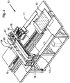
- Fig. 1 is a simplified perspective drawing of a garment printing system 10 not herein claimed but relevant to an understanding of the present invention.
- the garment printing system 10 comprises a rigid frame 11 in which an accurate linear motion X-axis stage 12 is installed.
- the X-axis stage 12 is a linear motor driven stage, and can be a conventional linear stage.
- the X-axis stage 12 can be any other type of linear stage, like a belt-driven stage, or ball screw driven stage.
- a printing table assembly 13 is connected to the X-axis stage 12, which preferably provides high acceleration and scanning speed.
- an accurate linear motion Y-axis stage 14 is installed above the printing table assembly 13, preferably on a bridge 15.
- the X-axis 12 and the Y-axis 14 stages are known in the art as linear stages, such as linear rails, like rails marketed by THK Co., Ltd., Tokyo, Japan, a linear encoder like that sold by RSF Elektronik Ges.m.b.H., Tarsdorf, Austria, and a moving plate supported on the rails.
- the X-axis stage 12 is a linear motor driven stage, capable of high acceleration rate and stiffness, for example, Anorad brand model LW10 of Rockwell Automation, Shirley, New York, USA.
- Closed loop control is responsible for the high accuracy and motion smoothness.
- the position of the printing table 13 along the rails of the X-axis stage 12 is measured by a linear encoder, and is used also to determine the firing timing of the inkjet nozzles and the wetting nozzles.
- the Y-axis stage 14 is preferably a linear motor stage similar to the X-axis stage 12.
- a printing head 16 preferably comprising a plurality of inkjet nozzles, is connected to a vertical Z-axis system 17, which is preferably a ball screw driven stage.
- the Z-axis stage 17 is supported on an Y-axis moving plate 18, to allow motion perpendicular to the direction of movement of the printing table 13.
- the gap between the printing heads array 16 and the printed surface on the printing table assembly 13 is an important parameter for high quality printing.
- the Z stage 17 enables movement of the printing heads array 16 in the vertical direction for calibration for different media heights.
- any other ink applying apparatus can be used for the printing head 16, such as a dripping nozzle, a droplet injector, a drop-on-demand piezoelectric inkjet nozzle, a continuous piezoelectric inkjet nozzle, a roller pad, an offset printing stencil and a screen printing stencil.
- the printing system 10 optionally comprises an ironing unit 19 and also optionally comprises a curing unit 20.
- the ironing unit 19 is preferably supported on the frame 11 above the X-axis stage 12, preferably on a bridge, such that the printing table assembly 13 can move underneath.
- the ironing unit 19 prepares the media for printing, as will be further explained in detail below.
- the curing unit 20 is preferably supported on the bridge 15 over the rigid frame 11. Alternatively, the curing unit 20 can be mounted over a separate bridge in a similar manner to the ironing unit 19.
- the curing unit 20 is an infrared heating unit that evaporates the ink carrier as printing is accomplished or during print passes.
- the curing unit 20 is a hot air blower.
- any other curing unit can be utilized, which is suited to the type of ink printed on the garment.
- Main computer 21 coordinates a large number of functions. It receives images from an image file, processes the images to be printed, activates the curing unit, and controls the motion systems, the ironing unit, and more. Preferably, movement of the X-axis and the Y-axis stages is coordinated by the microprocessor with the nozzles firing command by a print heads controller, so that precise printing of a desired object or symbol can be performed.
- computer 21 is augmented with a programmable logic controller (PLC), later shown and described in accordance with Fig. 4 .
- PLC programmable logic controller
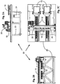
- Fig. 2A, Fig. 2B, and Fig. 2C are respectively side, front and top simplified views of a garment printing system 22 constructed and operative in accordance with the present invention.
- the printing system 22 comprises a frame 23 that is wider than frame 11 shown in Fig. 1 , and two independent linear X-axis stages 13 are installed instead of one X-axis stage, as in the embodiment described in Fig. 1 .
- Y-axis stage 14 described in Figs. 2A, 2B and. 2C is substantially the same as Y-axis stage 14 in Fig. 1 .
- the printing system 22 also comprises two curing units 20, two ironing units 19 and two printing table assemblies 13.
- the two X-axis stages 12 operate independently from one another.
- the process of loading and unloading can be carried out on one printing assembly at the same time that printing is being carried out on the second printing assembly.
- the printing heads array is working substantially continuously, dramatically improving throughput of the system.
- Each table can be accessed from the same edge of the system, thereby permitting a single worker to operate two printing assemblies.
- Main computer 21 controls both X-axis stages for independent operation.
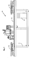
- Fig. 3 is a side view of a printing system 24 not claimed herein but relevant to an understanding of the present invention.
- the printing system 24 comprises a frame 11, which is the same as frame 11 shown in Fig. 1 and two independently movable printing table assemblies 13 mounted on the same X-axis stage 12.
- the printing table assemblies 13 are capable of moving back and forth independently of one another. Printing is performed on one printing table 13 while at the same time garments are unloaded and loaded on the second printing table. Each printing table 13 is accessed from the opposite edge of the system, and is loaded and unloaded by a different operator.
- Main computer 21 controls both printing tables.
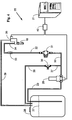
- Fig. 4 is a schematic illustration of a wetting system 25 constructed and operative in accordance with one embodiment of the present invention.
- the wetting system 25 can be added to a printing system, such as the printing systems 10, 22 and 24 described above.
- the wetting system 25 comprises a tank 26 containing the wetting composition 27, a pump 28, such as MGC4-MGC11DC available from Fluid-o-Tech of 23 via Morimondo, Milan, Italy, connected to the tank 26 through a pipe 29 and operative to pump the wetting composition 27 from the tank 26 to the spraying nozzle 19, such as 1101, available form Teejet, PO Box 7900, Wheaton, IL, USA, via pipe 30, pressure regulator 31, such as CM004R01, available form Camozzi, S.p.A. Via Eritrea 20/I, 25126 Brescia - Italy, pipe 32, manifold 33, pipe 34 and solenoid valve 35.
- a pump 28 such as MGC4-MGC11DC available from Fluid-o-Tech of 23 via Morimondo, Milan, Italy
- the spraying nozzle 19 such as 1101, available form Teejet, PO Box 7900, Wheaton, IL, USA
- pressure regulator 31 such as CM004R01, available form Camozzi, S.p.A.
- Overflow needle valve 36 such as GS0462216, available from Serto A.G., 25 Schutzenstr, CH-8355 Aadorf, Switzerland, is operative to carry excess wetting composition back to the tank 26 via pipes 37 and 38.
- Pipe 39 is also operative to carry overflow wetting composition from the solenoid valve 35 to the tank 26.
- a plurality of solenoid valves 35 and spraying nozzles 19 are constructed to form a battery of spraying nozzles as will be described below.
- PLC programmable logic controller
- the role of the PLC is to translate the commands effected by the computer 21 into electrical activation to the relevant components.
- a detailed description of the computer 21 procedure to operate the wetting system 25 is further shown and described below with reference to Fig 15 .
- the wetting the garment prior to printing limits the penetration of the ink into the garment so that a larger amount of ink remains on the external, visual, layers of the fabric, and that the printing head is thereafter capable of creating smaller dots of ink. Therefore the printed image has a higher quality, through higher resolution and stronger colors.
- the method and the apparatus for wetting the garment can be alternatively used to coat any other surface that is capable of absorbing the ink, or that has a relatively high surface tension with the ink liquid, so as to limit the smearing of the ink through, or over, the surface.
- the spraying nozzle 19 can be replaced by other means for applying liquid onto a surface, such as a dripping nozzle, a droplet injector, a drop-on-demand piezoelectric inkjet nozzle, a continuous piezoelectric inkjet nozzle, a roller pad, an offset printing stencil and a screen printing stencil.
- the printing head 16 can be replaced by other means for applying ink onto a surface, such as a dripping nozzle, a droplet injector, a drop-on-demand piezoelectric inkjet nozzle, a continuous piezoelectric inkjet nozzle, a roller pad, an offset printing stencil and a screen printing stencil, in any possible combination of wetting technology and printing technology.
- a dripping nozzle such as a dripping nozzle, a droplet injector, a drop-on-demand piezoelectric inkjet nozzle, a continuous piezoelectric inkjet nozzle, a roller pad, an offset printing stencil and a screen printing stencil, in any possible combination of wetting technology and printing technology.
- a dripping nozzle such as a dripping nozzle, a droplet injector, a drop-on-demand piezoelectric inkjet nozzle, a continuous piezoelectric inkjet nozzle, a roller pad, an offset printing stencil and a screen printing stencil, in any possible combination
- Fig. 5 is a perspective drawing of a battery 41 of solenoid valves 35 and spraying nozzles 19, constructed and operative in accordance with one embodiment of the present invention.
- the solenoid valves 35 are each connected via the pipe 34, the manifold 33 and the pipe 32 to the pressure regulator 31 (not shown in this figure).
- Fig. 6 is a perspective drawing of two batteries 41, mounted over a bridge 42 constructed and operative in accordance with one embodiment of the present invention. It is appreciated that alternatively the batteries 41 can be mounted on bridge 15 of Fig. 1 and Figs. 2A, 2B and 2C , preferably at the opposite side of the printing head 16.
- Fig. 7 is a simplified perspective drawing of a printing system 43 constructed and operative in accordance with one embodiment of the present invention.
- the printing system 43 is an improvement of the printing systems 10, 22 and 24 as shown and described in accordance with Figs. 1 , 2A, 2B, 2C and 3 by adding the pre-printing wetting assembly 25.
- printing system 43 is shown and described as an improvement of the twin axis printing system 22 shown and described in accordance with Figs. 2A, 2B, 2C .
- Fig. 7 shows the two batteries 41 mounted over the bridge 15, each battery over its respective X-axis 12. Each battery 41 is operative, separately and independently, to spray a wetting composition over the garment prior to printing, as will be described below.
- the operator instructs the computer 21 to start the printing process.
- the computer 21, with the aid of the PLC 40 moves the printing table 13, under the battery 41, until one edge of the area to be printed is placed directly below the battery 41.
- the computer 21 and the PLC 40 operate the adequate spraying nozzles 19, while moving the printing table 13 beneath, until at least a part of the area to be printed is wetted.
- the spraying nozzles are operated intermittently to apply adequate amount of wetting composition to the wetted area.
- the garment is ready for printing and the printing table 13 is moved under the printing head 16 to commence printing as will be described below.
- the computer 21 with the aid of the PLC 40, operate the curing assembly 20 while moving the printing table underneath, to cure, at least partially, the wetting composition, prior to printing.
- wetting assembly 25, as well as the printing system 43, can be easily modified for printing objects other than garments.
- Fig. 8 Fig. 9A and Fig. 9B
- the bath 44 is contains a thinner liquid, and is operative to dip the tips of the spraying nozzles 19 in this thinner liquid when the spraying nozzles are not spraying, as can be seen in Fig. 8 .
- the computer 21 activates the solenoid 45, also from Camozzi, to move the bath 44 and expose the tips of the spraying nozzles 19, as can be seen in Figs. 9A and 9B .
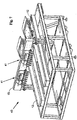
- Fig. 10 is simplified perspective drawings of a preferred embodiment of a garment mounting assembly 46, which is a part of the printing table 13, constructed and operative in accordance with one embodiment of the present invention.
- the garment mounting assembly 46 comprises a media-holding plate 47 and an openable cover 48.
- the media-holding plate 47 includes a raised portion 49 of the same size as the image to be printed
- the cover 48 includes a window 50 of the same shape as raised portion 49.
- the window 50 is slightly larger in size, preferably a few millimeters, than raised portion 49.
- the cover 48 is held in an open position by two gas cylinders 51, as known in the industry.
- at least part of the printing table assembly, for example the raised portion 40 is a vacuum table, to allow holding of non-porous media such as paper, boards, plastic etc.
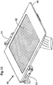
- FIG. 11 and Fig. 12 are simplified perspective drawings of the garment mounting assembly 46, with a mounted garment, in an opened and a closed positions, constructed and operative in accordance with one embodiment of the present invention.
- Fig. 11 shows a garment 52 loaded onto the garment mounting assembly 46.
- Garment 53 is loaded manually onto the media-holding plate, as the plate's chamfers 53 center the garment on the plate.
- the cover 48 is closed against the media-holding plate, while gas cylinders 51 urge the cover to the closed orientation.
- the edges of the garment are stretched slightly by the cover surface that touches the table's lower surface around the raised portion. As a result, the garment is held firmly in place to allow high-resolution printing (i.e., there is substantially no movement of the media during printing or wrinkling).
- the garment mounting assembly is a simple, flattened plate, made of aluminum or wood on which a textile piece or a garment is positioned.
- Flattened plates are well known by those who are familiar with the garment printing industry.
- Printing head assembly 54 comprises an array of printing heads 55, arranged for printing directly on a finished garment, a textile piece or other flexible or rigid medium.
- Each printing head 55 comprises at least one inkjet nozzle 56.
- Printing head 55 can be any conventional printing head, such as those marketed by Spectra, Inc., New Hampshire, USA and others known in the industry.
- printing heads assembly 54 is a massive array of conventional piezoelectric drop-on-demand or continuous inkjet heads, which perform the high-speed printing. It is a particular feature of the present invention that at least a 500, and preferably several thousands (i.e., 2,000) nozzles are provided for simultaneous printing, resulting in a very quick and accurate process.
- Each printing head 55 consists of dozens of nozzles 56 that are controlled independently by main computer 21, optionally via PLC 40.
- FIG. 14A, Fig. 14B, Fig.14C and Fig.14D are simplified schematic illustration of several stages of the printing process, according to a preferred embodiment of the present invention.
- Figs. 14A, 14B,14C and 14D show four consecutive passes of a part of a garment, such as garment 53 shown in Fig. 12 , under a single print head, such as the print head 56 of Fig. 13 .
- the distances between nozzles and between printing heads are bigger than the printing resolution, hence several print passes are needed to complete the image.
- the printing head 55 moves incrementally in the Y-axis to prepare for the next pass.
- the computer 21 is programmed to control the relative motion of the printing heads and the printing table assembly so as to obtain this accurate and complete coverage.
- the printing process is performed while relative motion occurs between the printing heads array 55 and the printing table assembly. At least two axes of motion are needed for this multi-color printing: X-axis motion that is in the printing direction; and Y-axis motion that is perpendicular to the printing direction. As stated above, the distances between nozzles and between printing heads are bigger than the printing resolution, hence several print passes are needed to complete the image. This is accomplished by moving the printing table assembly back and forth along the X-axis while moving the heads array perpendicular to the line of printing. The X-axis is the printing line and the Y-axis is the line on which the printing heads array moves after each pass to fill the gaps between printed lines in the next pass. Multi-color printing is performed as the table surface passes below the drop-on-demand inkjet nozzles array.
- the Y-axis is the fast-moving axis, while the X-axis moves incrementally to permit filling in of the gaps between printed lines.
- a printing command is sent by the printing heads driver (not shown) to each nozzle at the exact time and location for ink firing.
- the printing command is actually an electronic pulse, with exact width, voltage level, rise time and decay time.
- Printing heads drivers are commercial systems known in the industry, such as Inca drivers, of IncaDigital Printers, Cambridge, England.
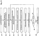
- Fig. 15 is a simplified flow chart of the process of wetting the garment prior to printing, preferably executed by the computer 21.
- the process of wetting the garment starts with element 57 by loading the image file from the computer's storage.
- the process progresses to element 58 to determine the edges of the image on the garment, which are also the edges of the area to be wetted.
- the process continues to element 59 to activate the X-axis 12, which moves the printing table 13.
- the process advances to element 60 to receive from the encoder the position data of the printing table 13.
- the process proceeds to element to determine which nozzles to open (element 61) or close (element 62) and sends the appropriate commands (elements 63 and 64) to the nozzle solenoids 35, preferably via the PLC 40.
- the process is stopped (element 66).
Landscapes
- General Health & Medical Sciences (AREA)
- Toxicology (AREA)
- Health & Medical Sciences (AREA)
- Engineering & Computer Science (AREA)
- Textile Engineering (AREA)
- Ink Jet (AREA)
- Treatment Of Fiber Materials (AREA)
- Dot-Matrix Printers And Others (AREA)
- Particle Formation And Scattering Control In Inkjet Printers (AREA)
- Pens And Brushes (AREA)
- Coloring (AREA)
- Printers Or Recording Devices Using Electromagnetic And Radiation Means (AREA)
- Handling Of Sheets (AREA)
- Ink Jet Recording Methods And Recording Media Thereof (AREA)
Abstract
Description
- The present invention relates to printing and, more particularly, but not exclusively to digital printing.
- Common printing methods employ liquid ink made of a pigment and an adhesive in a liquid, volatile, solvent. The liquid ink is applied to the printed substrate using a brush, pipe, stylus, rolling ball or cylinder, by sprinkling droplets such as an ink jet printer, by means of a printing pad or an offset stencil, by forcing the ink through a mesh stencil such as used with screen printing, etc.
- Printing using liquid ink requires that the ink remains at the point it is applied to the printed substrate until the solvent evaporates. When liquid ink is applied to substrates that are either absorbing, such as cloth, paper and cardboard, or have a high surface tension with the solvent, such as polished metal and glass, the liquid ink is smeared through or over the printed substrate creating a poor image quality
- Garment printing is performed today by screen printing press systems that are complex, inflexible, and require a specific set-up for each different print and color. First, an image file undergoes a mechanical spot-color separation process (each color is printed in black and white on a separate sheet of paper or film). Then, the image is "developed" in a long optical process, into a fine mesh (screen), which is pressed during the printing process against the media. Before printing, each screen has to be set in the proper station and adjusted with reference to the other screens. Ink is transferred to the garment through the mesh by mechanical means (generally wiping a squeegee along the screen). Garment screen-printing technology requires a special press station for each color level. Print quality is limited due to the high registration requirements between stations; hence printing resolution is relatively low.
- An attempt has been made to provide a device for printing onto a portion of a substrate, such as a garment.
US Patent 6,095,628 describes and claims an apparatus for inkjet printing pre-programmed viewable indicia onto a substrate. The apparatus is essentially a conventional ink jet printer, and is capable of creating the indicia through ink jet ink depositing upon flat or rigid substrates as a result of controlled platen movement beneath the ink jet printer head and controlled ink jet printer head movement and ink flow control by a programmed CPU. The flexible printing substrate of the patented invention is larger than the platen and portions of the substrate are draped downwardly over edges of the platen and tucked under the platen. - When printing on garments it is particularly important to limit the penetration of the ink into the depth of the fabric, which causes dull coloring of the garment.
- There is thus a widely recognized need for, and it would be highly advantageous to have, a printing system devoid of the above limitations.
-
US Patent Publication 2003197750 discloses a method of detecting an obstacle that disturbs a printing operation to be performed on a printing surface of a printing portion of a workpiece by a printing head of an ink-jet printer such that the printing head and a planar platen on which the printing portion of the workpiece is set are moved relative to each other between a first position and a second position, with a predetermined spacing maintained between the printing surface of the workpiece and the printing head in a direction perpendicular to the printing surface. The obstacle existing on a plane of printing by the printing head is detected by a sensing device, by scanning the predetermined spacing in a direction intersecting a direction of a relative movement of the printing head and the platen. At the same time the printing head and the platen are moved relative to each other between the first and second printing positions. Also disclosed are an ink-jet printing method and printer wherein the obstacle is detectable. -
US Patent publication No. 2002060728 discloses an ink-jet textile printing system which includes an ink-jet printing mechanism capable of textile printing on a printing object formed by a cloth product such as a T-shirt, a printing tray for holding a printing target range of the printing object flat, and conveying the printing object while positioning the printing target range with respect to the ink-jet printing mechanism, and a printing object formed by a cloth product such as a T-shirt having a partial pre-process portion obtained by partially pre-processing only the printing target range. - According to one aspect of the present invention there is provided a digital printing machine according to claim 1.
- Further advantageous embodiments of the invention are defined in claims 2-10.
- The invention is herein described, by way of example only, with reference to the accompanying drawings. With specific reference now to the drawings in detail, it is stressed that the particulars shown are by way of example and for purposes of illustrative discussion of the preferred embodiments of the present invention only, and are presented in order to provide what is believed to be the most useful and readily understood description of the principles and conceptual aspects of the invention. In this regard, no attempt is made to show structural details of the invention in more detail than is necessary for a fundamental understanding of the invention, the description taken with the drawings making apparent to those skilled in the art how the several forms of the invention may be embodied in practice.
- In the drawings:
-
Fig. 1 is a simplified perspective drawing of a garment printing system constructed and operative in accordance with an embodiment not claimed herein but relevant to an understanding of the present invention; -
Fig. 2A, Fig. 2B and Fig. 2C are respectively side, front and top simplified views of a garment printing system constructed and operative in accordance with the present invention; -
Fig. 3 is a simplified side view drawing of a garment printing system constructed and operative in accordance with an embodiment not claimed herein but relevant to an understanding of the present invention; -
Fig. 4 is a schematic illustration of a wetting system constructed and operative in accordance with one embodiment of the present invention; -
Fig. 5 is a perspective drawing of a wetting battery of solenoid valves and spraying nozzles; -
Fig. 6 is a perspective drawing of two wetting batteries mounted over a bridge; -
Fig. 7 is a simplified perspective drawing of the printing system ofFigs. 2A, 2B and 2C equipped with the wetting system ofFig. 4 ; -
Fig. 8 ,Fig. 9A and Fig. 9B are simplified perspective drawings of a preferred embodiment of the battery ofFig. 5 equipped with a bath of thinner liquid; -
Fig. 10 is simplified perspective drawings of a preferred embodiment of a garment mounting assembly; -
Fig. 11 andFig. 12 are simplified perspective drawings of the garment mounting assembly ofFig. 10 with a mounted garment in an open and a close position; -
Fig. 13 is a simplified schematic drawing of an inkjet printing head assembly; -
Fig. 14A, Fig. 14B, Fig. 14C, and Fig. 14D , taken together, are simplified schematic illustrations of several stages of the printing process, according to a preferred embodiment of the present invention; and -
Fig. 15 is a simplified flow chart of the process of wetting the garment prior to printing. - The principles and operation of a printing apparatus according to the present invention may be better understood with reference to the drawings and accompanying description.
- Before explaining at least one embodiment of the invention in detail, it is to be understood that the invention is not limited in its application to the details of construction and the arrangement of the components set forth in the following description or illustrated in the drawings. The invention is capable of other embodiments or of being practiced or carried out in various ways. Also, it is to be understood that the phraseology and terminology employed herein is for the purpose of description and should not be regarded as limiting.
- The present invention relates to a digital printing system for various substrates that permits accurate, high quality, high resolution, multi-color printing directly onto a substrate in a relatively simple system. A preferred embodiment of the present invention is useful for printing over materials that usually cause the ink to smear over the material, such as fibrous materials, porous materials and other ink absorbing materials, and materials having high surface tension with the ink liquid. A preferred embodiment of the present invention is thus provided for the garment industry in general, and for T-shirt printing industry in particular.
- A preferred embodiment of the present invention comprises a pre-printing assembly for wetting the substrate prior to printing. This wetting sub-system typically comprises an array of spraying nozzles operative to apply a wetting composition over the printed material. This wetting composition interferes with the engagement of the ink with the printed material so as to limit the spread of the ink over, or within, the material;
- A printing assembly comprising at least one printing head operative to apply ink on the printed material;
- A garment handling assembly;
- Optionally, at least one curing assembly, operative to cure the wetting composition, or the ink liquid, or both;
- Optionally, at least one ironing assembly, operative to iron the garment prior to printing or wetting; and
- A controller unit for controlling the operation of the above assemblies, typically comprising a computer, preferably comprising a microcontroller, or a programmable logic controller (PLC), or a personal computer (PC) or any combination thereof.
- The abovementioned wetting assembly and printing assembly preferably comprises of one or more units capable of applying liquid over selected areas of the material to be printed. Such units are known in the art as spraying nozzles, dripping nozzles, droplet injectors, drop-on-demand piezoelectric inkjet nozzles, continuous piezoelectric inkjet nozzles, roller pads, stamping pads, offset printing stencil and a screen printing stencil, etc.
- The abovementioned garment handling assembly preferably comprises an accurate X, Y, Z motion system and a printing table. Since the printing system is particularly suited to printing on a garment, it has been described herein with respect to garment printing, by way of example only. However, it will be appreciated that any other suitable substrate can alternatively be utilized.
- A preferred embodiment of a digital printing system according to the present invention typically comprises electronically controlled wetting and printing units such as spraying nozzles, dripping nozzles, droplet injectors, drop-on-demand piezoelectric inkjet nozzles, continuous piezoelectric inkjet nozzles, etc. that are capable of creating image pixels in a controllable manner.
- A preferred embodiment of the present invention shown and described below comprises the combination of wetting by spraying technology and printing by inkjet technology. It is appreciated that the present invention pertains to every possible combination of wetting technology and printing technology.
- The digital printing system has the following advantages over conventional screen-printing devices:
- The image file is received in conventional format without the need for spot color separation process.
- No screen or stencil development is needed.
- The transition from one job to another does not require replacement of screens, cleaning, etc.
- Printing flexibility: the image can be modified for each print. Variable data is printed at the same speed.
- The image can be printed in a variety of color levels.
- The system occupies a smaller floor area.
- Higher printing resolution can be achieved.
- Printing files are stored efficiently in a way that eliminates the need for large screen storage area and screen cleaning processes.
- Printing directly onto a garment or textile obviates the need for transfer paper and an additional transfer step.
- Reference is now made to
Fig. 1 , which is a simplified perspective drawing of agarment printing system 10 not herein claimed but relevant to an understanding of the present invention. Thegarment printing system 10 comprises arigid frame 11 in which an accurate linear motionX-axis stage 12 is installed. According to one embodiment, theX-axis stage 12 is a linear motor driven stage, and can be a conventional linear stage. Alternatively, theX-axis stage 12 can be any other type of linear stage, like a belt-driven stage, or ball screw driven stage. Aprinting table assembly 13 is connected to theX-axis stage 12, which preferably provides high acceleration and scanning speed. - Perpendicular to the X-axis direction, an accurate linear motion Y-
axis stage 14 is installed above theprinting table assembly 13, preferably on abridge 15. TheX-axis 12 and the Y-axis 14 stages are known in the art as linear stages, such as linear rails, like rails marketed by THK Co., Ltd., Tokyo, Japan, a linear encoder like that sold by RSF Elektronik Ges.m.b.H., Tarsdorf, Austria, and a moving plate supported on the rails. According to a preferred embodiment of the invention, theX-axis stage 12 is a linear motor driven stage, capable of high acceleration rate and stiffness, for example, Anorad brand model LW10 of Rockwell Automation, Shirley, New York, USA. Closed loop control is responsible for the high accuracy and motion smoothness. The position of the printing table 13 along the rails of theX-axis stage 12 is measured by a linear encoder, and is used also to determine the firing timing of the inkjet nozzles and the wetting nozzles. The Y-axis stage 14 is preferably a linear motor stage similar to theX-axis stage 12. - A
printing head 16, preferably comprising a plurality of inkjet nozzles, is connected to a vertical Z-axis system 17, which is preferably a ball screw driven stage. The Z-axis stage 17 is supported on an Y-axis moving plate 18, to allow motion perpendicular to the direction of movement of the printing table 13. The gap between the printing headsarray 16 and the printed surface on theprinting table assembly 13 is an important parameter for high quality printing. TheZ stage 17 enables movement of the printing headsarray 16 in the vertical direction for calibration for different media heights. - It is appreciated that any other ink applying apparatus can be used for the
printing head 16, such as a dripping nozzle, a droplet injector, a drop-on-demand piezoelectric inkjet nozzle, a continuous piezoelectric inkjet nozzle, a roller pad, an offset printing stencil and a screen printing stencil. - It is also appreciated that, while the system is particularly suited for printing on a finished garment, other media can alternatively be employed. The present invention will be described with regard to a finished garment, for ease of description by way of example.
- The
printing system 10 optionally comprises anironing unit 19 and also optionally comprises acuring unit 20. Theironing unit 19 is preferably supported on theframe 11 above theX-axis stage 12, preferably on a bridge, such that theprinting table assembly 13 can move underneath. Theironing unit 19 prepares the media for printing, as will be further explained in detail below. The curingunit 20 is preferably supported on thebridge 15 over therigid frame 11. Alternatively, the curingunit 20 can be mounted over a separate bridge in a similar manner to theironing unit 19. According to one embodiment of the present invention the curingunit 20 is an infrared heating unit that evaporates the ink carrier as printing is accomplished or during print passes. According to another embodiment of the present invention the curingunit 20 is a hot air blower. Alternatively, any other curing unit can be utilized, which is suited to the type of ink printed on the garment. - A
main computer 21, preferably a microprocessor, controls the entire system, and is coupled to each of the various units for coordination, synchronization, and activation, in accordance with a pre-programmed printing process.Main computer 21 coordinates a large number of functions. It receives images from an image file, processes the images to be printed, activates the curing unit, and controls the motion systems, the ironing unit, and more. Preferably, movement of the X-axis and the Y-axis stages is coordinated by the microprocessor with the nozzles firing command by a print heads controller, so that precise printing of a desired object or symbol can be performed. In a preferred embodiment of the present invention,computer 21 is augmented with a programmable logic controller (PLC), later shown and described in accordance withFig. 4 . - Reference is now made to
Fig. 2A, Fig. 2B, and Fig. 2C , which are respectively side, front and top simplified views of agarment printing system 22 constructed and operative in accordance with the present invention. Theprinting system 22 comprises aframe 23 that is wider thanframe 11 shown inFig. 1 , and two independent linearX-axis stages 13 are installed instead of one X-axis stage, as in the embodiment described inFig. 1 . Y-axis stage 14 described inFigs. 2A, 2B and. 2C is substantially the same as Y-axis stage 14 inFig. 1 . Theprinting system 22 also comprises two curingunits 20, two ironingunits 19 and twoprinting table assemblies 13. It is a particular feature of the present embodiment that the twoX-axis stages 12 operate independently from one another. Thus, the process of loading and unloading can be carried out on one printing assembly at the same time that printing is being carried out on the second printing assembly. As a result, the printing heads array is working substantially continuously, dramatically improving throughput of the system. Each table can be accessed from the same edge of the system, thereby permitting a single worker to operate two printing assemblies.Main computer 21 controls both X-axis stages for independent operation. - Reference is now made to
Fig. 3 , which is a side view of aprinting system 24 not claimed herein but relevant to an understanding of the present invention. Theprinting system 24 comprises aframe 11, which is the same asframe 11 shown inFig. 1 and two independently movableprinting table assemblies 13 mounted on the sameX-axis stage 12. Theprinting table assemblies 13 are capable of moving back and forth independently of one another. Printing is performed on one printing table 13 while at the same time garments are unloaded and loaded on the second printing table. Each printing table 13 is accessed from the opposite edge of the system, and is loaded and unloaded by a different operator.Main computer 21 controls both printing tables. - Reference is now made to
Fig. 4 , which is a schematic illustration of a wettingsystem 25 constructed and operative in accordance with one embodiment of the present invention. The wettingsystem 25 can be added to a printing system, such as theprinting systems system 25 comprises atank 26 containing the wettingcomposition 27, apump 28, such as MGC4-MGC11DC available from Fluid-o-Tech of 23 via Morimondo, Milan, Italy, connected to thetank 26 through apipe 29 and operative to pump the wettingcomposition 27 from thetank 26 to the sprayingnozzle 19, such as 1101, available form Teejet, PO Box 7900, Wheaton, IL, USA, viapipe 30,pressure regulator 31, such as CM004R01, available form Camozzi, S.p.A. ViaEritrea 20/I, 25126 Brescia - Italy,pipe 32,manifold 33,pipe 34 andsolenoid valve 35.Overflow needle valve 36, such as GS0462216, available from Serto A.G., 25 Schutzenstr, CH-8355 Aadorf, Switzerland, is operative to carry excess wetting composition back to thetank 26 viapipes Pipe 39 is also operative to carry overflow wetting composition from thesolenoid valve 35 to thetank 26. Preferably, a plurality ofsolenoid valves 35 and sprayingnozzles 19 are constructed to form a battery of spraying nozzles as will be described below. When wetting is initiated, as will be described below, thecomputer 21, preferably with the aid of a programmable logic controller (PLC) 40, activates thepump 29, and then solenoidvalve 35, to inject streams of the wettingcomposition 27. In a preferred embodiment of the present invention shown and described in accordance withFigs. 4 andFig 15 , the role of the PLC is to translate the commands effected by thecomputer 21 into electrical activation to the relevant components. A detailed description of thecomputer 21 procedure to operate the wettingsystem 25 is further shown and described below with reference toFig 15 . - It is appreciated that the wetting the garment prior to printing limits the penetration of the ink into the garment so that a larger amount of ink remains on the external, visual, layers of the fabric, and that the printing head is thereafter capable of creating smaller dots of ink. Therefore the printed image has a higher quality, through higher resolution and stronger colors.
- It is also appreciated that the method and the apparatus for wetting the garment can be alternatively used to coat any other surface that is capable of absorbing the ink, or that has a relatively high surface tension with the ink liquid, so as to limit the smearing of the ink through, or over, the surface.
- It is further appreciated that the spraying
nozzle 19 can be replaced by other means for applying liquid onto a surface, such as a dripping nozzle, a droplet injector, a drop-on-demand piezoelectric inkjet nozzle, a continuous piezoelectric inkjet nozzle, a roller pad, an offset printing stencil and a screen printing stencil. - It is additionally appreciated that the
printing head 16 can be replaced by other means for applying ink onto a surface, such as a dripping nozzle, a droplet injector, a drop-on-demand piezoelectric inkjet nozzle, a continuous piezoelectric inkjet nozzle, a roller pad, an offset printing stencil and a screen printing stencil, in any possible combination of wetting technology and printing technology. Such possible combinations include, but are not limited to: - Wetting using dripping and printing using drop-on-demand piezoelectric inkjet nozzle;
- Wetting using roller pad and printing using continuous piezoelectric inkjet nozzle;
- Wetting using spraying and printing using screen printing stencil; and
- Wetting using droplet injector and printing using inkjet nozzle.
- Reference is now made to
Fig. 5 , which is a perspective drawing of abattery 41 ofsolenoid valves 35 and sprayingnozzles 19, constructed and operative in accordance with one embodiment of the present invention. Thesolenoid valves 35 are each connected via thepipe 34, the manifold 33 and thepipe 32 to the pressure regulator 31 (not shown in this figure). - Reference is now made to
Fig. 6 , which is a perspective drawing of twobatteries 41, mounted over abridge 42 constructed and operative in accordance with one embodiment of the present invention. It is appreciated that alternatively thebatteries 41 can be mounted onbridge 15 ofFig. 1 andFigs. 2A, 2B and 2C , preferably at the opposite side of theprinting head 16. - Reference is now made to
Fig. 7 , which is a simplified perspective drawing of aprinting system 43 constructed and operative in accordance with one embodiment of the present invention. Theprinting system 43 is an improvement of theprinting systems Figs. 1 ,2A, 2B, 2C and3 by adding thepre-printing wetting assembly 25. For simplicity,printing system 43 is shown and described as an improvement of the twinaxis printing system 22 shown and described in accordance withFigs. 2A, 2B, 2C .Fig. 7 shows the twobatteries 41 mounted over thebridge 15, each battery over itsrespective X-axis 12. Eachbattery 41 is operative, separately and independently, to spray a wetting composition over the garment prior to printing, as will be described below. - After mounting the garment on the printing table 13, as will be described in further details below, the operator instructs the
computer 21 to start the printing process. Thecomputer 21, with the aid of thePLC 40, moves the printing table 13, under thebattery 41, until one edge of the area to be printed is placed directly below thebattery 41. Then thecomputer 21 and thePLC 40 operate theadequate spraying nozzles 19, while moving the printing table 13 beneath, until at least a part of the area to be printed is wetted. Preferably all and only the area to be printed is wetted. Preferably the spraying nozzles are operated intermittently to apply adequate amount of wetting composition to the wetted area. At this stage the garment is ready for printing and the printing table 13 is moved under theprinting head 16 to commence printing as will be described below. - It is appreciated that the operation of selected spraying
nozzles 19 while moving the garment below enables the wetting of only selected areas of the garment, particularly those areas to be printed, while other areas are left intact. - Optionally the
computer 21, with the aid of thePLC 40, operate the curingassembly 20 while moving the printing table underneath, to cure, at least partially, the wetting composition, prior to printing. - It is appreciated that the wetting
assembly 25, as well as theprinting system 43, can be easily modified for printing objects other than garments. - Reference is now made to
Fig. 8 ,Fig. 9A and Fig. 9B , which are all simplified perspective drawings of a preferred embodiment of thebattery 41 equipped with abath 44, constructed and operative in accordance with one embodiment of the present invention. Thebath 44 is contains a thinner liquid, and is operative to dip the tips of the sprayingnozzles 19 in this thinner liquid when the spraying nozzles are not spraying, as can be seen inFig. 8 . Before spraying is initiated, thecomputer 21 activates the solenoid 45, also from Camozzi, to move thebath 44 and expose the tips of the sprayingnozzles 19, as can be seen inFigs. 9A and 9B . - Reference is now made to
Fig. 10 , which is simplified perspective drawings of a preferred embodiment of agarment mounting assembly 46, which is a part of the printing table 13, constructed and operative in accordance with one embodiment of the present invention. Thegarment mounting assembly 46 comprises a media-holdingplate 47 and anopenable cover 48. Preferably, the media-holdingplate 47 includes a raisedportion 49 of the same size as the image to be printed, and thecover 48 includes awindow 50 of the same shape as raisedportion 49. Preferably, thewindow 50 is slightly larger in size, preferably a few millimeters, than raisedportion 49. Thecover 48 is held in an open position by twogas cylinders 51, as known in the industry. Preferably, at least part of the printing table assembly, for example the raisedportion 40, is a vacuum table, to allow holding of non-porous media such as paper, boards, plastic etc. - Reference is now made to
Fig. 11 andFig. 12 , which are simplified perspective drawings of thegarment mounting assembly 46, with a mounted garment, in an opened and a closed positions, constructed and operative in accordance with one embodiment of the present invention.Fig. 11 shows agarment 52 loaded onto thegarment mounting assembly 46.Garment 53 is loaded manually onto the media-holding plate, as the plate'schamfers 53 center the garment on the plate. As can be seen inFig 12 , after thegarment 53 is loaded onto the media-holding plate, thecover 48 is closed against the media-holding plate, whilegas cylinders 51 urge the cover to the closed orientation. The edges of the garment are stretched slightly by the cover surface that touches the table's lower surface around the raised portion. As a result, the garment is held firmly in place to allow high-resolution printing (i.e., there is substantially no movement of the media during printing or wrinkling). - According to another embodiment of this invention, the garment mounting assembly is a simple, flattened plate, made of aluminum or wood on which a textile piece or a garment is positioned. Flattened plates are well known by those who are familiar with the garment printing industry.
- Reference is now made to
Fig. 13 , which is a simplified schematic drawing of an inkjetprinting head assembly 54, constructed and operative in accordance with one embodiment of the present invention.Printing head assembly 54 comprises an array of printing heads 55, arranged for printing directly on a finished garment, a textile piece or other flexible or rigid medium. Eachprinting head 55 comprises at least oneinkjet nozzle 56.Printing head 55 can be any conventional printing head, such as those marketed by Spectra, Inc., New Hampshire, USA and others known in the industry. - According to one preferred embodiment of the invention, printing heads
assembly 54 is a massive array of conventional piezoelectric drop-on-demand or continuous inkjet heads, which perform the high-speed printing. It is a particular feature of the present invention that at least a 500, and preferably several thousands (i.e., 2,000) nozzles are provided for simultaneous printing, resulting in a very quick and accurate process. Eachprinting head 55 consists of dozens ofnozzles 56 that are controlled independently bymain computer 21, optionally viaPLC 40. - Reference is now made to
Fig. 14A, Fig. 14B, Fig.14C and Fig.14D , which, taken together, are simplified schematic illustration of several stages of the printing process, according to a preferred embodiment of the present invention.Figs. 14A, 14B,14C and 14D , show four consecutive passes of a part of a garment, such asgarment 53 shown inFig. 12 , under a single print head, such as theprint head 56 ofFig. 13 . - According to a preferred embodiment, the distances between nozzles and between printing heads are bigger than the printing resolution, hence several print passes are needed to complete the image. After each pass in the X-axis, here created by movement of the printing table assembly with
media 53, theprinting head 55 moves incrementally in the Y-axis to prepare for the next pass. It will be appreciated that thecomputer 21 is programmed to control the relative motion of the printing heads and the printing table assembly so as to obtain this accurate and complete coverage. - The printing process is performed while relative motion occurs between the printing heads
array 55 and the printing table assembly. At least two axes of motion are needed for this multi-color printing: X-axis motion that is in the printing direction; and Y-axis motion that is perpendicular to the printing direction. As stated above, the distances between nozzles and between printing heads are bigger than the printing resolution, hence several print passes are needed to complete the image. This is accomplished by moving the printing table assembly back and forth along the X-axis while moving the heads array perpendicular to the line of printing. The X-axis is the printing line and the Y-axis is the line on which the printing heads array moves after each pass to fill the gaps between printed lines in the next pass. Multi-color printing is performed as the table surface passes below the drop-on-demand inkjet nozzles array. - According to an alternative embodiment of the invention, the Y-axis is the fast-moving axis, while the X-axis moves incrementally to permit filling in of the gaps between printed lines.
- A printing command is sent by the printing heads driver (not shown) to each nozzle at the exact time and location for ink firing. The printing command is actually an electronic pulse, with exact width, voltage level, rise time and decay time. Printing heads drivers are commercial systems known in the industry, such as Inca drivers, of IncaDigital Printers, Cambridge, England. When printing is completed, the printing table is moved to a loading position. Then, the printed garment is unloaded and a new garment is loaded onto the printing table.
- Reference is now made to
Fig. 15 , which is a simplified flow chart of the process of wetting the garment prior to printing, preferably executed by thecomputer 21. The process of wetting the garment starts withelement 57 by loading the image file from the computer's storage. The process progresses toelement 58 to determine the edges of the image on the garment, which are also the edges of the area to be wetted. The process continues toelement 59 to activate theX-axis 12, which moves the printing table 13. The process advances toelement 60 to receive from the encoder the position data of the printing table 13. The process proceeds to element to determine which nozzles to open (element 61) or close (element 62) and sends the appropriate commands (elements 63 and 64) to thenozzle solenoids 35, preferably via thePLC 40. When the other edge of the image is reached (element 65) the process is stopped (element 66). - The printing system of the embodiments described above incorporates three processes, one after the other:
- 1. Loading and unloading garments.
- 2. Wetting at least a part of the area of the garment to be printed.
- 3. Printing an image on the mounted over at least a part of the wetted area.
- In order to increase the throughput of the system, these processes can be performed in parallel, as seen in the above embodiments of the invention.
- It will be appreciated that the invention is not limited to what has been described hereinabove merely by way of example. Rather, the invention is limited solely by the claims that follow.
- It is expected that during the life of this patent many relevant liquid applicator devices and ink applicator devices and systems will be developed and the scope of the terms herein, particularly of the terms "spraying nozzles" and "inkjet nozzles", is intended to include all such new technologies a priori.
- Additional objects, advantages, and novel features of the present invention will become apparent to one ordinarily skilled in the art upon examination of the following examples, which are not intended to be limiting. Additionally, each of the various embodiments and aspects of the present invention as delineated hereinabove and as claimed in the claims section below finds experimental support in the following examples.
- It is appreciated that certain features of the invention, which are, for clarity, described in the context of separate embodiments, may also be provided in combination in a single embodiment. Conversely, various features of the invention, which are, for brevity, described in the context of a single embodiment, may also be provided separately or in any suitable subcombination.
- Although the invention has been described in conjunction with specific embodiments thereof, it is evident that many alternatives, modifications and variations will be apparent to those skilled in the art. Accordingly, it is intended to embrace all such alternatives, modifications and variations that fall within the scope of the appended claims.
Claims (10)
- A digital printing machine comprising:a rigid frame;a first linear motion X axis stage mounted on said frame;a second linear motion X axis stage mounted on said frame parallel to said first axis stage, and arranged for operation independently of said first axis stage;a printing table assembly movable on each said linear X axis stage;a linear motion Y axis stage mounted on said frame perpendicular to said linear X axis stages, above said printing table assemblies; andan array of inkjet nozzles mounted on said linear Y axis stage for linear motion perpendicular to said X axis stage.
- The printing machine of claim 1, wherein each said printing table assembly comprises a media-holding plate and an openable cover pivotally coupled to said media-holding plate for holding said media firmly against said plate.
- The printing machine according to claim 2, wherein said media-holding plate includes a raised portion, and said cover includes a window of the same shape and slightly larger than said raised portion.
- The printing machine according to claim 1, wherein at least one of said linear motion X axis stage and said linear motion Y axis stage is a linear motor driven stage.
- The printing machine according to claim 1, where at least part of each said printing table assembly is a vacuum table.
- The printing machine according to claim 1, wherein said inkjet nozzles include drop-on-demand piezoelectric inkjet nozzles or continuous piezoelectric inkjet nozzles.
- The printing machine according to claim 1, further comprising a curing unit located above each said printing table assembly and arranged to cure ink on media on said printing table assembly.
- The printing machine according to claim 7, wherein said curing unit is an infrared system or a hot air blowing unit.
- The printing machine according to claim 1, further comprising an ironing unit located above each said printing table assembly and arranged to iron media on said printing table assembly.
- The printing machine according to claim 1, wherein said printing table assembly is a flattened plate.
Applications Claiming Priority (3)
| Application Number | Priority Date | Filing Date | Title |
|---|---|---|---|
| US10/776,163 US7607745B2 (en) | 2004-02-12 | 2004-02-12 | Digital printing machine |
| IL162231A IL162231A (en) | 2004-05-30 | 2004-05-30 | Process for direct digital inkjet printing onto a wet textile piece |
| PCT/IL2005/000166 WO2005076730A2 (en) | 2004-02-12 | 2005-02-10 | A digital printing apparatus |
Publications (3)
| Publication Number | Publication Date |
|---|---|
| EP1740388A2 EP1740388A2 (en) | 2007-01-10 |
| EP1740388A4 EP1740388A4 (en) | 2009-09-23 |
| EP1740388B1 true EP1740388B1 (en) | 2012-04-11 |
Family
ID=34863276
Family Applications (1)
| Application Number | Title | Priority Date | Filing Date |
|---|---|---|---|
| EP05703208A Expired - Lifetime EP1740388B1 (en) | 2004-02-12 | 2005-02-10 | A digital printing apparatus |
Country Status (6)
| Country | Link |
|---|---|
| EP (1) | EP1740388B1 (en) |
| JP (1) | JP2007525339A (en) |
| AT (1) | ATE552981T1 (en) |
| DK (1) | DK1740388T3 (en) |
| IL (1) | IL177323A (en) |
| WO (1) | WO2005076730A2 (en) |
Cited By (1)
| Publication number | Priority date | Publication date | Assignee | Title |
|---|---|---|---|---|
| CN107921786A (en) * | 2015-07-20 | 2018-04-17 | 易安技术有限责任公司 | Apparatus and method for printed fabric surface |
Families Citing this family (36)
| Publication number | Priority date | Publication date | Assignee | Title |
|---|---|---|---|---|
| IL162231A (en) | 2004-05-30 | 2007-05-15 | Kornit Digital Ltd | Process for direct digital inkjet printing onto a wet textile piece |
| US11447648B2 (en) | 2004-05-30 | 2022-09-20 | Kornit Digital Ltd. | Process and system for printing images on absorptive surfaces |
| JP4840221B2 (en) | 2007-03-29 | 2011-12-21 | ブラザー工業株式会社 | Printing device |
| WO2008151453A1 (en) * | 2007-06-15 | 2008-12-18 | Wp Digital Ag | Method for printing endless printing substrates digitally |
| US9550374B1 (en) | 2007-06-27 | 2017-01-24 | Cafepress Inc. | System and method for improved digital printing on textiles |
| JP2009101592A (en) * | 2007-10-23 | 2009-05-14 | Brother Ind Ltd | Printing apparatus, computer program, and storage medium |
| GB2457098B (en) * | 2008-02-04 | 2012-11-07 | Inca Digital Printers Ltd | Flatbed printer |
| JP5062427B2 (en) | 2008-03-24 | 2012-10-31 | ブラザー工業株式会社 | Printing device |
| JP2009279887A (en) * | 2008-05-26 | 2009-12-03 | Brother Ind Ltd | Printer |
| JP2009279888A (en) * | 2008-05-26 | 2009-12-03 | Brother Ind Ltd | Printing device |
| CN102656237B (en) | 2009-08-10 | 2014-07-09 | 柯尼特数码有限公司 | Inkjet compositions and methods for stretchable substrates |
| US8926080B2 (en) | 2010-08-10 | 2015-01-06 | Kornit Digital Ltd. | Formaldehyde-free inkjet compositions and processes |
| FR2966381A1 (en) * | 2010-10-20 | 2012-04-27 | Aerostatique De Promotion S A P Soc | Device for printing e.g. customized object for clubs, has maintaining unit connected to driving unit and translation guiding unit, and adjusting unit that adjusts height of receiving unit of printing block with respect to frame |
| US8801127B2 (en) | 2011-01-31 | 2014-08-12 | Kornit Digital Technologies Ltd. | Method and apparatus for safe use of a wet on wet textile printer |
| DE112012002210A5 (en) * | 2011-05-23 | 2014-07-24 | Digidirect Gmbh | printing system |
| JP5853593B2 (en) * | 2011-10-28 | 2016-02-09 | セイコーエプソン株式会社 | PRINTED MATERIAL SUPPORT DEVICE, PRINTING DEVICE, AND PRINTED PRODUCTION METHOD |
| US9266318B2 (en) * | 2013-05-01 | 2016-02-23 | Nike, Inc. | Printing system with retractable screen assembly |
| US9114625B2 (en) * | 2013-06-26 | 2015-08-25 | Nike, Inc. | Additive color printing |
| GB2518423A (en) * | 2013-09-23 | 2015-03-25 | Gew Ec Ltd | UV ink curing apparatus |
| IL228964B (en) * | 2013-10-20 | 2019-07-31 | Matan Digital Printing Ltd | Triple mode printer |
| US20170056900A1 (en) * | 2015-08-31 | 2017-03-02 | The Procter & Gamble Company | Parallel Motion Apparatus for Depositing a Substance on Articles |
| JP6922285B2 (en) * | 2016-05-06 | 2021-08-18 | 株式会社リコー | Image addition system, printing device, fabric holding member, holding member with cloth |
| WO2018078634A1 (en) | 2016-10-31 | 2018-05-03 | Kornit Digital Ltd. | Dye-sublimation inkjet printing for textile |
| JP6885225B2 (en) * | 2017-05-01 | 2021-06-09 | 株式会社リコー | Cloth holding member, printing device, image imparting device, holding member of printed member, heating device |
| CN107284029B (en) * | 2017-08-11 | 2018-10-16 | 南通金康弘纺织品有限公司 | A kind of digital decorating machine |
| JP2019075319A (en) * | 2017-10-18 | 2019-05-16 | 株式会社リコー | Heating device, image applying device, and image applying method |
| JP2021500437A (en) | 2017-10-22 | 2021-01-07 | コーニット・デジタル・リミテッド | Low friction image by inkjet printing |
| JPWO2019208048A1 (en) | 2018-04-27 | 2021-04-22 | 京セラドキュメントソリューションズ株式会社 | Ink ejection device, printing device, and control method of ink ejection device |
| JP2019206103A (en) | 2018-05-28 | 2019-12-05 | 京セラドキュメントソリューションズ株式会社 | Ink discharge device and printer |
| CN108528065A (en) * | 2018-06-11 | 2018-09-14 | 北京美科艺数码科技发展有限公司 | A kind of inkjet-printing device |
| CN110155701B (en) * | 2019-04-01 | 2024-08-06 | 威海新鸣球进出口有限公司 | A fully automatic digital direct-injection textile printing machine |
| JP7097614B2 (en) * | 2019-06-12 | 2022-07-08 | 株式会社ウイル | High-speed tag issuing device and tag manufacturing method |
| KR102093748B1 (en) * | 2019-07-19 | 2020-03-26 | 염규연 | Manufacturing method for protective net |
| EP4065762A4 (en) | 2019-11-26 | 2023-12-27 | Kornit Digital Ltd. | METHOD OF PRINTING ON SYNTHETIC FABRICS DYED USING A DYE TRANSFER MATERIAL |
| CN111703217B (en) * | 2020-07-21 | 2024-11-26 | 天津筑高机器人技术有限公司 | PCB Printer |
| DE102022105761A1 (en) | 2022-03-11 | 2023-09-14 | Koenig & Bauer Ag | Inkjet printing machine, system comprising two inkjet printing machines and use of an inkjet printing machine |
Family Cites Families (23)
| Publication number | Priority date | Publication date | Assignee | Title |
|---|---|---|---|---|
| JPS6099081A (en) * | 1983-11-04 | 1985-06-01 | 東レ株式会社 | Ink jet dyeing method |
| JPS6175870A (en) * | 1984-09-21 | 1986-04-18 | 東レ株式会社 | Ink jet dyeing apparatus |
| JPS63168382A (en) * | 1986-12-29 | 1988-07-12 | Nagase Sangyo Kk | Ink jet dyeing method for cellulose fibrous structure |
| US5412411A (en) * | 1993-11-26 | 1995-05-02 | Xerox Corporation | Capping station for an ink-jet printer with immersion of printhead in ink |
| EP0679759A1 (en) * | 1994-04-11 | 1995-11-02 | Gerber Scientific Products, Inc. | Method and apparatus for printing graphics directly on fabrics |
| JPH08232176A (en) * | 1995-02-28 | 1996-09-10 | Canon Inc | INKJET PRINTING METHOD AND PRINTED PRINTED BY THE METHOD |
| US6095628A (en) | 1996-07-19 | 2000-08-01 | Rhome; Matthew | Apparatus for ink jet printing |
| US5757407A (en) * | 1996-11-25 | 1998-05-26 | Xerox Corporation | Liquid ink printer having multiple pass drying |
| JPH10278379A (en) * | 1997-04-09 | 1998-10-20 | Seiko Epson Corp | Printing apparatus, printing method, and recording medium |
| US6059391A (en) * | 1997-08-19 | 2000-05-09 | Fulkerson; Timothy Jerome | Apparatus and method for ink jet printing on large or irregular fabrics |
| JP3474814B2 (en) * | 1999-09-29 | 2003-12-08 | カネボウ株式会社 | Treatment agent for ink-jet printing of cellulosic fiber and / or protein fiber, printing cloth and printing method |
| KR100342445B1 (en) * | 1999-12-29 | 2002-07-02 | 박상업 | An ink-jet printer for digital textiling |
| US6536894B1 (en) * | 2000-06-06 | 2003-03-25 | Hewlett-Packard Company | Print media heating techniques for a vacuum belt hard copy apparatus |
| JP4374747B2 (en) * | 2000-07-21 | 2009-12-02 | コニカミノルタホールディングス株式会社 | Inkjet recording device |
| US6755518B2 (en) * | 2001-08-30 | 2004-06-29 | L&P Property Management Company | Method and apparatus for ink jet printing on rigid panels |
| JP2002154247A (en) * | 2000-11-17 | 2002-05-28 | Canon Electronics Inc | Ink jet printing apparatus and ink jet printing method |
| US6631985B2 (en) * | 2000-11-17 | 2003-10-14 | Canon Denshi Kabushiki Kaisha | Ink-jet textile printing system, ink-jet textile printing apparatus, and ink-jet textile printing method |
| CA2442429A1 (en) * | 2001-03-30 | 2002-10-10 | L & P Property Management Company | Method and apparatus for ink jet printing |
| JP2003159787A (en) * | 2001-11-28 | 2003-06-03 | Seiko Epson Corp | Discharge method and apparatus, electro-optical apparatus, method for manufacturing the same and apparatus for manufacturing the same, color filter, method for manufacturing the same and apparatus for manufacturing the same, device having base material, method for manufacturing the same, and apparatus for manufacturing the same |
| EP1405723B1 (en) * | 2002-03-26 | 2011-05-18 | Mastermind Co., Ltd. | Three-dimensionally printed image creating method and three-dimensionally printed article |
| JP3969168B2 (en) * | 2002-04-23 | 2007-09-05 | ブラザー工業株式会社 | Platen device for inkjet printer |
| JP4089277B2 (en) * | 2002-04-23 | 2008-05-28 | ブラザー工業株式会社 | Printhead interference detection device for ink jet printer |
| JP4234964B2 (en) * | 2002-09-10 | 2009-03-04 | 株式会社オーク製作所 | Exposure equipment |
-
2005
- 2005-02-10 WO PCT/IL2005/000166 patent/WO2005076730A2/en not_active Ceased
- 2005-02-10 DK DK05703208.8T patent/DK1740388T3/en active
- 2005-02-10 EP EP05703208A patent/EP1740388B1/en not_active Expired - Lifetime
- 2005-02-10 AT AT05703208T patent/ATE552981T1/en active
- 2005-02-10 JP JP2006552776A patent/JP2007525339A/en active Pending
-
2006
- 2006-08-07 IL IL177323A patent/IL177323A/en active IP Right Grant
Cited By (2)
| Publication number | Priority date | Publication date | Assignee | Title |
|---|---|---|---|---|
| CN107921786A (en) * | 2015-07-20 | 2018-04-17 | 易安技术有限责任公司 | Apparatus and method for printed fabric surface |
| CN107921786B (en) * | 2015-07-20 | 2019-09-10 | 易安技术有限责任公司 | Device and method for printed fabric surface |
Also Published As
| Publication number | Publication date |
|---|---|
| JP2007525339A (en) | 2007-09-06 |
| WO2005076730A2 (en) | 2005-08-25 |
| IL177323A (en) | 2011-12-29 |
| ATE552981T1 (en) | 2012-04-15 |
| EP1740388A4 (en) | 2009-09-23 |
| DK1740388T3 (en) | 2012-07-23 |
| EP1740388A2 (en) | 2007-01-10 |
| WO2005076730A3 (en) | 2007-03-08 |
| IL177323A0 (en) | 2008-03-20 |
Similar Documents
| Publication | Publication Date | Title |
|---|---|---|
| US7954921B2 (en) | Digital printing apparatus | |
| US7607745B2 (en) | Digital printing machine | |
| WO2005076730A2 (en) | A digital printing apparatus | |
| EP1893413B1 (en) | Combined stencil and digital printing system | |
| US6513897B2 (en) | Multiple resolution fluid applicator and method | |
| US6059391A (en) | Apparatus and method for ink jet printing on large or irregular fabrics | |
| CN109808300B (en) | Composite printing device | |
| RU2009105881A (en) | METHOD AND DEVICE FOR DECORING A Rough SURFACE OF A STABLE FORM SUBJECT | |
| EP1750945A2 (en) | A process and system for printing images on absorptive surfaces | |
| CN112829467A (en) | Continuous image-text splicing method for ink-jet printer | |
| US20200157367A1 (en) | Process and system for printing images on absorptive surfaces | |
| CN108712967A (en) | Printing equipment | |
| CN112829466A (en) | Continuous image-text splicing method for ink-jet printer | |
| CN100400301C (en) | Inkjet printing method and system | |
| US9242481B2 (en) | Method of applying a curable liquid and apparatus for performing the method | |
| CN113905889A (en) | Ink-jet printer and one-pass ink-jet printing method | |
| US20240316949A1 (en) | Printing method | |
| CN116409067A (en) | Hot stamping method and equipment for curved printing medium | |
| CN101389484A (en) | Drying Systems for Imaging Machines | |
| US20090249969A1 (en) | Printer having increased solution volume of printing and increased print quality and speed | |
| JP2024137642A (en) | Printing method | |
| CN215512870U (en) | Ink-jet printing device | |
| JP3790119B2 (en) | How to paint building boards | |
| JP3557226B2 (en) | Plate making and printing equipment | |
| JP2026504170A (en) | Method for operating a printing device, printing device, and software product |
Legal Events
| Date | Code | Title | Description |
|---|---|---|---|
| PUAI | Public reference made under article 153(3) epc to a published international application that has entered the european phase |
Free format text: ORIGINAL CODE: 0009012 |
|
| 17P | Request for examination filed |
Effective date: 20060823 |
|
| AK | Designated contracting states |
Kind code of ref document: A2 Designated state(s): AT BE BG CH CY CZ DE DK EE ES FI FR GB GR HU IE IS IT LI LT LU MC NL PL PT RO SE SI SK TR |
|
| AX | Request for extension of the european patent |
Extension state: AL BA HR LV MK YU |
|
| PUAK | Availability of information related to the publication of the international search report |
Free format text: ORIGINAL CODE: 0009015 |
|
| DAX | Request for extension of the european patent (deleted) | ||
| A4 | Supplementary search report drawn up and despatched |
Effective date: 20090826 |
|
| RIC1 | Information provided on ipc code assigned before grant |
Ipc: B41J 3/407 20060101ALI20090820BHEP Ipc: B41J 3/28 20060101AFI20061129BHEP |
|
| 17Q | First examination report despatched |
Effective date: 20091112 |
|
| RAP1 | Party data changed (applicant data changed or rights of an application transferred) |
Owner name: KORNIT DIGITAL TECHNOLOGIES LTD. |
|
| GRAP | Despatch of communication of intention to grant a patent |
Free format text: ORIGINAL CODE: EPIDOSNIGR1 |
|
| RIN1 | Information on inventor provided before grant (corrected) |
Inventor name: PEARL, YOSSI Inventor name: BEN-ZUR, OFER |
|
| GRAS | Grant fee paid |
Free format text: ORIGINAL CODE: EPIDOSNIGR3 |
|
| RAP1 | Party data changed (applicant data changed or rights of an application transferred) |
Owner name: KORNIT DIGITAL TECHNOLOGIES LTD. |
|
| GRAA | (expected) grant |
Free format text: ORIGINAL CODE: 0009210 |
|
| AK | Designated contracting states |
Kind code of ref document: B1 Designated state(s): AT BE BG CH CY CZ DE DK EE ES FI FR GB GR HU IE IS IT LI LT LU MC NL PL PT RO SE SI SK TR |
|
| REG | Reference to a national code |
Ref country code: GB Ref legal event code: FG4D |
|
| REG | Reference to a national code |
Ref country code: CH Ref legal event code: EP |
|
| REG | Reference to a national code |
Ref country code: AT Ref legal event code: REF Ref document number: 552981 Country of ref document: AT Kind code of ref document: T Effective date: 20120415 |
|
| REG | Reference to a national code |
Ref country code: IE Ref legal event code: FG4D |
|
| REG | Reference to a national code |
Ref country code: DE Ref legal event code: R096 Ref document number: 602005033586 Country of ref document: DE Effective date: 20120606 |
|
| REG | Reference to a national code |
Ref country code: NL Ref legal event code: T3 |
|
| REG | Reference to a national code |
Ref country code: DK Ref legal event code: T3 |
|
| LTIE | Lt: invalidation of european patent or patent extension |
Effective date: 20120411 |
|
| PG25 | Lapsed in a contracting state [announced via postgrant information from national office to epo] |
Ref country code: PL Free format text: LAPSE BECAUSE OF FAILURE TO SUBMIT A TRANSLATION OF THE DESCRIPTION OR TO PAY THE FEE WITHIN THE PRESCRIBED TIME-LIMIT Effective date: 20120411 Ref country code: LT Free format text: LAPSE BECAUSE OF FAILURE TO SUBMIT A TRANSLATION OF THE DESCRIPTION OR TO PAY THE FEE WITHIN THE PRESCRIBED TIME-LIMIT Effective date: 20120411 Ref country code: CY Free format text: LAPSE BECAUSE OF FAILURE TO SUBMIT A TRANSLATION OF THE DESCRIPTION OR TO PAY THE FEE WITHIN THE PRESCRIBED TIME-LIMIT Effective date: 20120411 Ref country code: IS Free format text: LAPSE BECAUSE OF FAILURE TO SUBMIT A TRANSLATION OF THE DESCRIPTION OR TO PAY THE FEE WITHIN THE PRESCRIBED TIME-LIMIT Effective date: 20120811 Ref country code: SE Free format text: LAPSE BECAUSE OF FAILURE TO SUBMIT A TRANSLATION OF THE DESCRIPTION OR TO PAY THE FEE WITHIN THE PRESCRIBED TIME-LIMIT Effective date: 20120411 Ref country code: FI Free format text: LAPSE BECAUSE OF FAILURE TO SUBMIT A TRANSLATION OF THE DESCRIPTION OR TO PAY THE FEE WITHIN THE PRESCRIBED TIME-LIMIT Effective date: 20120411 |
|
| PG25 | Lapsed in a contracting state [announced via postgrant information from national office to epo] |
Ref country code: SI Free format text: LAPSE BECAUSE OF FAILURE TO SUBMIT A TRANSLATION OF THE DESCRIPTION OR TO PAY THE FEE WITHIN THE PRESCRIBED TIME-LIMIT Effective date: 20120411 Ref country code: GR Free format text: LAPSE BECAUSE OF FAILURE TO SUBMIT A TRANSLATION OF THE DESCRIPTION OR TO PAY THE FEE WITHIN THE PRESCRIBED TIME-LIMIT Effective date: 20120712 Ref country code: PT Free format text: LAPSE BECAUSE OF FAILURE TO SUBMIT A TRANSLATION OF THE DESCRIPTION OR TO PAY THE FEE WITHIN THE PRESCRIBED TIME-LIMIT Effective date: 20120813 |
|
| PG25 | Lapsed in a contracting state [announced via postgrant information from national office to epo] |
Ref country code: BE Free format text: LAPSE BECAUSE OF FAILURE TO SUBMIT A TRANSLATION OF THE DESCRIPTION OR TO PAY THE FEE WITHIN THE PRESCRIBED TIME-LIMIT Effective date: 20120411 |
|
| PG25 | Lapsed in a contracting state [announced via postgrant information from national office to epo] |
Ref country code: EE Free format text: LAPSE BECAUSE OF FAILURE TO SUBMIT A TRANSLATION OF THE DESCRIPTION OR TO PAY THE FEE WITHIN THE PRESCRIBED TIME-LIMIT Effective date: 20120411 Ref country code: RO Free format text: LAPSE BECAUSE OF FAILURE TO SUBMIT A TRANSLATION OF THE DESCRIPTION OR TO PAY THE FEE WITHIN THE PRESCRIBED TIME-LIMIT Effective date: 20120411 Ref country code: SK Free format text: LAPSE BECAUSE OF FAILURE TO SUBMIT A TRANSLATION OF THE DESCRIPTION OR TO PAY THE FEE WITHIN THE PRESCRIBED TIME-LIMIT Effective date: 20120411 Ref country code: CZ Free format text: LAPSE BECAUSE OF FAILURE TO SUBMIT A TRANSLATION OF THE DESCRIPTION OR TO PAY THE FEE WITHIN THE PRESCRIBED TIME-LIMIT Effective date: 20120411 |
|
| PLBE | No opposition filed within time limit |
Free format text: ORIGINAL CODE: 0009261 |
|
| STAA | Information on the status of an ep patent application or granted ep patent |
Free format text: STATUS: NO OPPOSITION FILED WITHIN TIME LIMIT |
|
| 26N | No opposition filed |
Effective date: 20130114 |
|
| PG25 | Lapsed in a contracting state [announced via postgrant information from national office to epo] |
Ref country code: ES Free format text: LAPSE BECAUSE OF FAILURE TO SUBMIT A TRANSLATION OF THE DESCRIPTION OR TO PAY THE FEE WITHIN THE PRESCRIBED TIME-LIMIT Effective date: 20120722 |
|
| REG | Reference to a national code |
Ref country code: DE Ref legal event code: R097 Ref document number: 602005033586 Country of ref document: DE Effective date: 20130114 |
|
| PG25 | Lapsed in a contracting state [announced via postgrant information from national office to epo] |
Ref country code: BG Free format text: LAPSE BECAUSE OF FAILURE TO SUBMIT A TRANSLATION OF THE DESCRIPTION OR TO PAY THE FEE WITHIN THE PRESCRIBED TIME-LIMIT Effective date: 20120711 |
|
| PG25 | Lapsed in a contracting state [announced via postgrant information from national office to epo] |
Ref country code: MC Free format text: LAPSE BECAUSE OF NON-PAYMENT OF DUE FEES Effective date: 20130228 |
|
| REG | Reference to a national code |
Ref country code: IE Ref legal event code: MM4A |
|
| PG25 | Lapsed in a contracting state [announced via postgrant information from national office to epo] |
Ref country code: IE Free format text: LAPSE BECAUSE OF NON-PAYMENT OF DUE FEES Effective date: 20130210 |
|
| PG25 | Lapsed in a contracting state [announced via postgrant information from national office to epo] |
Ref country code: TR Free format text: LAPSE BECAUSE OF FAILURE TO SUBMIT A TRANSLATION OF THE DESCRIPTION OR TO PAY THE FEE WITHIN THE PRESCRIBED TIME-LIMIT Effective date: 20120411 |
|
| PG25 | Lapsed in a contracting state [announced via postgrant information from national office to epo] |
Ref country code: HU Free format text: LAPSE BECAUSE OF FAILURE TO SUBMIT A TRANSLATION OF THE DESCRIPTION OR TO PAY THE FEE WITHIN THE PRESCRIBED TIME-LIMIT; INVALID AB INITIO Effective date: 20050210 Ref country code: LU Free format text: LAPSE BECAUSE OF NON-PAYMENT OF DUE FEES Effective date: 20130210 |
|
| REG | Reference to a national code |
Ref country code: FR Ref legal event code: PLFP Year of fee payment: 12 |
|
| REG | Reference to a national code |
Ref country code: FR Ref legal event code: PLFP Year of fee payment: 13 |
|
| REG | Reference to a national code |
Ref country code: FR Ref legal event code: PLFP Year of fee payment: 14 |
|
| REG | Reference to a national code |
Ref country code: DE Ref legal event code: R008 Ref document number: 602005033586 Country of ref document: DE Ref country code: DE Ref legal event code: R039 Ref document number: 602005033586 Country of ref document: DE |
|
| PGFP | Annual fee paid to national office [announced via postgrant information from national office to epo] |
Ref country code: DK Payment date: 20220218 Year of fee payment: 18 Ref country code: CH Payment date: 20220216 Year of fee payment: 18 |
|
| PGFP | Annual fee paid to national office [announced via postgrant information from national office to epo] |
Ref country code: NL Payment date: 20220216 Year of fee payment: 18 |
|
| REG | Reference to a national code |
Ref country code: DE Ref legal event code: R040 Ref document number: 602005033586 Country of ref document: DE |
|
| P01 | Opt-out of the competence of the unified patent court (upc) registered |
Effective date: 20230515 |
|
| REG | Reference to a national code |
Ref country code: DK Ref legal event code: EBP Effective date: 20230228 |
|
| REG | Reference to a national code |
Ref country code: CH Ref legal event code: PL |
|
| REG | Reference to a national code |
Ref country code: NL Ref legal event code: MM Effective date: 20230301 |
|
| PG25 | Lapsed in a contracting state [announced via postgrant information from national office to epo] |
Ref country code: LI Free format text: LAPSE BECAUSE OF NON-PAYMENT OF DUE FEES Effective date: 20230228 Ref country code: CH Free format text: LAPSE BECAUSE OF NON-PAYMENT OF DUE FEES Effective date: 20230228 |
|
| PG25 | Lapsed in a contracting state [announced via postgrant information from national office to epo] |
Ref country code: NL Free format text: LAPSE BECAUSE OF NON-PAYMENT OF DUE FEES Effective date: 20230301 |
|
| PG25 | Lapsed in a contracting state [announced via postgrant information from national office to epo] |
Ref country code: DK Free format text: LAPSE BECAUSE OF NON-PAYMENT OF DUE FEES Effective date: 20230228 |
|
| PGFP | Annual fee paid to national office [announced via postgrant information from national office to epo] |
Ref country code: AT Payment date: 20240220 Year of fee payment: 20 |
|
| PGFP | Annual fee paid to national office [announced via postgrant information from national office to epo] |
Ref country code: DE Payment date: 20240219 Year of fee payment: 20 Ref country code: GB Payment date: 20240219 Year of fee payment: 20 |
|
| PGFP | Annual fee paid to national office [announced via postgrant information from national office to epo] |
Ref country code: IT Payment date: 20240228 Year of fee payment: 20 Ref country code: FR Payment date: 20240220 Year of fee payment: 20 |
|
| REG | Reference to a national code |
Ref country code: DE Ref legal event code: R071 Ref document number: 602005033586 Country of ref document: DE |
|
| REG | Reference to a national code |
Ref country code: GB Ref legal event code: PE20 Expiry date: 20250209 |
|
| REG | Reference to a national code |
Ref country code: AT Ref legal event code: MK07 Ref document number: 552981 Country of ref document: AT Kind code of ref document: T Effective date: 20250210 |
|
| PG25 | Lapsed in a contracting state [announced via postgrant information from national office to epo] |
Ref country code: GB Free format text: LAPSE BECAUSE OF EXPIRATION OF PROTECTION Effective date: 20250209 |