EP1739779A1 - dispositif pour la génération d'energie thermique et electrique - Google Patents
dispositif pour la génération d'energie thermique et electrique Download PDFInfo
- Publication number
- EP1739779A1 EP1739779A1 EP06012825A EP06012825A EP1739779A1 EP 1739779 A1 EP1739779 A1 EP 1739779A1 EP 06012825 A EP06012825 A EP 06012825A EP 06012825 A EP06012825 A EP 06012825A EP 1739779 A1 EP1739779 A1 EP 1739779A1
- Authority
- EP
- European Patent Office
- Prior art keywords
- chamber
- connection
- gas
- air
- fuel cell
- Prior art date
- Legal status (The legal status is an assumption and is not a legal conclusion. Google has not performed a legal analysis and makes no representation as to the accuracy of the status listed.)
- Granted
Links
Images
Classifications
-
- C—CHEMISTRY; METALLURGY
- C01—INORGANIC CHEMISTRY
- C01B—NON-METALLIC ELEMENTS; COMPOUNDS THEREOF; METALLOIDS OR COMPOUNDS THEREOF NOT COVERED BY SUBCLASS C01C
- C01B3/00—Hydrogen; Gaseous mixtures containing hydrogen; Separation of hydrogen from mixtures containing it; Purification of hydrogen
- C01B3/02—Production of hydrogen or of gaseous mixtures containing a substantial proportion of hydrogen
- C01B3/32—Production of hydrogen or of gaseous mixtures containing a substantial proportion of hydrogen by reaction of gaseous or liquid organic compounds with gasifying agents, e.g. water, carbon dioxide, air
- C01B3/34—Production of hydrogen or of gaseous mixtures containing a substantial proportion of hydrogen by reaction of gaseous or liquid organic compounds with gasifying agents, e.g. water, carbon dioxide, air by reaction of hydrocarbons with gasifying agents
- C01B3/38—Production of hydrogen or of gaseous mixtures containing a substantial proportion of hydrogen by reaction of gaseous or liquid organic compounds with gasifying agents, e.g. water, carbon dioxide, air by reaction of hydrocarbons with gasifying agents using catalysts
- C01B3/384—Production of hydrogen or of gaseous mixtures containing a substantial proportion of hydrogen by reaction of gaseous or liquid organic compounds with gasifying agents, e.g. water, carbon dioxide, air by reaction of hydrocarbons with gasifying agents using catalysts the catalyst being continuously externally heated
-
- F—MECHANICAL ENGINEERING; LIGHTING; HEATING; WEAPONS; BLASTING
- F23—COMBUSTION APPARATUS; COMBUSTION PROCESSES
- F23C—METHODS OR APPARATUS FOR COMBUSTION USING FLUID FUEL OR SOLID FUEL SUSPENDED IN A CARRIER GAS OR AIR
- F23C9/00—Combustion apparatus characterised by arrangements for returning combustion products or flue gases to the combustion chamber
-
- F—MECHANICAL ENGINEERING; LIGHTING; HEATING; WEAPONS; BLASTING
- F23—COMBUSTION APPARATUS; COMBUSTION PROCESSES
- F23D—BURNERS
- F23D14/00—Burners for combustion of a gas, e.g. of a gas stored under pressure as a liquid
- F23D14/46—Details, e.g. noise reduction means
- F23D14/62—Mixing devices; Mixing tubes
-
- H—ELECTRICITY
- H01—ELECTRIC ELEMENTS
- H01M—PROCESSES OR MEANS, e.g. BATTERIES, FOR THE DIRECT CONVERSION OF CHEMICAL ENERGY INTO ELECTRICAL ENERGY
- H01M8/00—Fuel cells; Manufacture thereof
- H01M8/04—Auxiliary arrangements, e.g. for control of pressure or for circulation of fluids
- H01M8/04007—Auxiliary arrangements, e.g. for control of pressure or for circulation of fluids related to heat exchange
- H01M8/04014—Heat exchange using gaseous fluids; Heat exchange by combustion of reactants
- H01M8/04022—Heating by combustion
-
- H—ELECTRICITY
- H01—ELECTRIC ELEMENTS
- H01M—PROCESSES OR MEANS, e.g. BATTERIES, FOR THE DIRECT CONVERSION OF CHEMICAL ENERGY INTO ELECTRICAL ENERGY
- H01M8/00—Fuel cells; Manufacture thereof
- H01M8/04—Auxiliary arrangements, e.g. for control of pressure or for circulation of fluids
- H01M8/04082—Arrangements for control of reactant parameters, e.g. pressure or concentration
- H01M8/04089—Arrangements for control of reactant parameters, e.g. pressure or concentration of gaseous reactants
- H01M8/04119—Arrangements for control of reactant parameters, e.g. pressure or concentration of gaseous reactants with simultaneous supply or evacuation of electrolyte; Humidifying or dehumidifying
- H01M8/04156—Arrangements for control of reactant parameters, e.g. pressure or concentration of gaseous reactants with simultaneous supply or evacuation of electrolyte; Humidifying or dehumidifying with product water removal
-
- H—ELECTRICITY
- H01—ELECTRIC ELEMENTS
- H01M—PROCESSES OR MEANS, e.g. BATTERIES, FOR THE DIRECT CONVERSION OF CHEMICAL ENERGY INTO ELECTRICAL ENERGY
- H01M8/00—Fuel cells; Manufacture thereof
- H01M8/06—Combination of fuel cells with means for production of reactants or for treatment of residues
- H01M8/0606—Combination of fuel cells with means for production of reactants or for treatment of residues with means for production of gaseous reactants
- H01M8/0612—Combination of fuel cells with means for production of reactants or for treatment of residues with means for production of gaseous reactants from carbon-containing material
- H01M8/0625—Combination of fuel cells with means for production of reactants or for treatment of residues with means for production of gaseous reactants from carbon-containing material in a modular combined reactor/fuel cell structure
- H01M8/0631—Reactor construction specially adapted for combination reactor/fuel cell
-
- C—CHEMISTRY; METALLURGY
- C01—INORGANIC CHEMISTRY
- C01B—NON-METALLIC ELEMENTS; COMPOUNDS THEREOF; METALLOIDS OR COMPOUNDS THEREOF NOT COVERED BY SUBCLASS C01C
- C01B2203/00—Integrated processes for the production of hydrogen or synthesis gas
- C01B2203/02—Processes for making hydrogen or synthesis gas
- C01B2203/0205—Processes for making hydrogen or synthesis gas containing a reforming step
- C01B2203/0227—Processes for making hydrogen or synthesis gas containing a reforming step containing a catalytic reforming step
- C01B2203/0233—Processes for making hydrogen or synthesis gas containing a reforming step containing a catalytic reforming step the reforming step being a steam reforming step
-
- C—CHEMISTRY; METALLURGY
- C01—INORGANIC CHEMISTRY
- C01B—NON-METALLIC ELEMENTS; COMPOUNDS THEREOF; METALLOIDS OR COMPOUNDS THEREOF NOT COVERED BY SUBCLASS C01C
- C01B2203/00—Integrated processes for the production of hydrogen or synthesis gas
- C01B2203/04—Integrated processes for the production of hydrogen or synthesis gas containing a purification step for the hydrogen or the synthesis gas
- C01B2203/0465—Composition of the impurity
- C01B2203/0495—Composition of the impurity the impurity being water
-
- C—CHEMISTRY; METALLURGY
- C01—INORGANIC CHEMISTRY
- C01B—NON-METALLIC ELEMENTS; COMPOUNDS THEREOF; METALLOIDS OR COMPOUNDS THEREOF NOT COVERED BY SUBCLASS C01C
- C01B2203/00—Integrated processes for the production of hydrogen or synthesis gas
- C01B2203/06—Integration with other chemical processes
- C01B2203/066—Integration with other chemical processes with fuel cells
-
- C—CHEMISTRY; METALLURGY
- C01—INORGANIC CHEMISTRY
- C01B—NON-METALLIC ELEMENTS; COMPOUNDS THEREOF; METALLOIDS OR COMPOUNDS THEREOF NOT COVERED BY SUBCLASS C01C
- C01B2203/00—Integrated processes for the production of hydrogen or synthesis gas
- C01B2203/08—Methods of heating or cooling
- C01B2203/0805—Methods of heating the process for making hydrogen or synthesis gas
- C01B2203/0811—Methods of heating the process for making hydrogen or synthesis gas by combustion of fuel
- C01B2203/0822—Methods of heating the process for making hydrogen or synthesis gas by combustion of fuel the fuel containing hydrogen
-
- C—CHEMISTRY; METALLURGY
- C01—INORGANIC CHEMISTRY
- C01B—NON-METALLIC ELEMENTS; COMPOUNDS THEREOF; METALLOIDS OR COMPOUNDS THEREOF NOT COVERED BY SUBCLASS C01C
- C01B2203/00—Integrated processes for the production of hydrogen or synthesis gas
- C01B2203/08—Methods of heating or cooling
- C01B2203/0805—Methods of heating the process for making hydrogen or synthesis gas
- C01B2203/0811—Methods of heating the process for making hydrogen or synthesis gas by combustion of fuel
- C01B2203/0827—Methods of heating the process for making hydrogen or synthesis gas by combustion of fuel at least part of the fuel being a recycle stream
-
- C—CHEMISTRY; METALLURGY
- C01—INORGANIC CHEMISTRY
- C01B—NON-METALLIC ELEMENTS; COMPOUNDS THEREOF; METALLOIDS OR COMPOUNDS THEREOF NOT COVERED BY SUBCLASS C01C
- C01B2203/00—Integrated processes for the production of hydrogen or synthesis gas
- C01B2203/08—Methods of heating or cooling
- C01B2203/0872—Methods of cooling
-
- C—CHEMISTRY; METALLURGY
- C01—INORGANIC CHEMISTRY
- C01B—NON-METALLIC ELEMENTS; COMPOUNDS THEREOF; METALLOIDS OR COMPOUNDS THEREOF NOT COVERED BY SUBCLASS C01C
- C01B2203/00—Integrated processes for the production of hydrogen or synthesis gas
- C01B2203/12—Feeding the process for making hydrogen or synthesis gas
- C01B2203/1205—Composition of the feed
- C01B2203/1211—Organic compounds or organic mixtures used in the process for making hydrogen or synthesis gas
- C01B2203/1235—Hydrocarbons
- C01B2203/1241—Natural gas or methane
-
- C—CHEMISTRY; METALLURGY
- C01—INORGANIC CHEMISTRY
- C01B—NON-METALLIC ELEMENTS; COMPOUNDS THEREOF; METALLOIDS OR COMPOUNDS THEREOF NOT COVERED BY SUBCLASS C01C
- C01B2203/00—Integrated processes for the production of hydrogen or synthesis gas
- C01B2203/12—Feeding the process for making hydrogen or synthesis gas
- C01B2203/1276—Mixing of different feed components
-
- F—MECHANICAL ENGINEERING; LIGHTING; HEATING; WEAPONS; BLASTING
- F23—COMBUSTION APPARATUS; COMBUSTION PROCESSES
- F23C—METHODS OR APPARATUS FOR COMBUSTION USING FLUID FUEL OR SOLID FUEL SUSPENDED IN A CARRIER GAS OR AIR
- F23C2202/00—Fluegas recirculation
- F23C2202/20—Premixing fluegas with fuel
-
- F—MECHANICAL ENGINEERING; LIGHTING; HEATING; WEAPONS; BLASTING
- F23—COMBUSTION APPARATUS; COMBUSTION PROCESSES
- F23C—METHODS OR APPARATUS FOR COMBUSTION USING FLUID FUEL OR SOLID FUEL SUSPENDED IN A CARRIER GAS OR AIR
- F23C2900/00—Special features of, or arrangements for combustion apparatus using fluid fuels or solid fuels suspended in air; Combustion processes therefor
- F23C2900/03002—Combustion apparatus adapted for incorporating a fuel reforming device
-
- H—ELECTRICITY
- H01—ELECTRIC ELEMENTS
- H01M—PROCESSES OR MEANS, e.g. BATTERIES, FOR THE DIRECT CONVERSION OF CHEMICAL ENERGY INTO ELECTRICAL ENERGY
- H01M8/00—Fuel cells; Manufacture thereof
- H01M8/10—Fuel cells with solid electrolytes
- H01M2008/1095—Fuel cells with polymeric electrolytes
-
- H—ELECTRICITY
- H01—ELECTRIC ELEMENTS
- H01M—PROCESSES OR MEANS, e.g. BATTERIES, FOR THE DIRECT CONVERSION OF CHEMICAL ENERGY INTO ELECTRICAL ENERGY
- H01M2250/00—Fuel cells for particular applications; Specific features of fuel cell system
- H01M2250/40—Combination of fuel cells with other energy production systems
- H01M2250/405—Cogeneration of heat or hot water
-
- H—ELECTRICITY
- H01—ELECTRIC ELEMENTS
- H01M—PROCESSES OR MEANS, e.g. BATTERIES, FOR THE DIRECT CONVERSION OF CHEMICAL ENERGY INTO ELECTRICAL ENERGY
- H01M8/00—Fuel cells; Manufacture thereof
- H01M8/04—Auxiliary arrangements, e.g. for control of pressure or for circulation of fluids
- H01M8/04082—Arrangements for control of reactant parameters, e.g. pressure or concentration
- H01M8/04197—Preventing means for fuel crossover
-
- Y—GENERAL TAGGING OF NEW TECHNOLOGICAL DEVELOPMENTS; GENERAL TAGGING OF CROSS-SECTIONAL TECHNOLOGIES SPANNING OVER SEVERAL SECTIONS OF THE IPC; TECHNICAL SUBJECTS COVERED BY FORMER USPC CROSS-REFERENCE ART COLLECTIONS [XRACs] AND DIGESTS
- Y02—TECHNOLOGIES OR APPLICATIONS FOR MITIGATION OR ADAPTATION AGAINST CLIMATE CHANGE
- Y02B—CLIMATE CHANGE MITIGATION TECHNOLOGIES RELATED TO BUILDINGS, e.g. HOUSING, HOUSE APPLIANCES OR RELATED END-USER APPLICATIONS
- Y02B90/00—Enabling technologies or technologies with a potential or indirect contribution to GHG emissions mitigation
- Y02B90/10—Applications of fuel cells in buildings
-
- Y—GENERAL TAGGING OF NEW TECHNOLOGICAL DEVELOPMENTS; GENERAL TAGGING OF CROSS-SECTIONAL TECHNOLOGIES SPANNING OVER SEVERAL SECTIONS OF THE IPC; TECHNICAL SUBJECTS COVERED BY FORMER USPC CROSS-REFERENCE ART COLLECTIONS [XRACs] AND DIGESTS
- Y02—TECHNOLOGIES OR APPLICATIONS FOR MITIGATION OR ADAPTATION AGAINST CLIMATE CHANGE
- Y02E—REDUCTION OF GREENHOUSE GAS [GHG] EMISSIONS, RELATED TO ENERGY GENERATION, TRANSMISSION OR DISTRIBUTION
- Y02E60/00—Enabling technologies; Technologies with a potential or indirect contribution to GHG emissions mitigation
- Y02E60/30—Hydrogen technology
- Y02E60/50—Fuel cells
-
- Y—GENERAL TAGGING OF NEW TECHNOLOGICAL DEVELOPMENTS; GENERAL TAGGING OF CROSS-SECTIONAL TECHNOLOGIES SPANNING OVER SEVERAL SECTIONS OF THE IPC; TECHNICAL SUBJECTS COVERED BY FORMER USPC CROSS-REFERENCE ART COLLECTIONS [XRACs] AND DIGESTS
- Y02—TECHNOLOGIES OR APPLICATIONS FOR MITIGATION OR ADAPTATION AGAINST CLIMATE CHANGE
- Y02P—CLIMATE CHANGE MITIGATION TECHNOLOGIES IN THE PRODUCTION OR PROCESSING OF GOODS
- Y02P20/00—Technologies relating to chemical industry
- Y02P20/10—Process efficiency
- Y02P20/129—Energy recovery, e.g. by cogeneration, H2recovery or pressure recovery turbines
Definitions
- the invention relates to a device for providing thermal and electrical energy according to the preamble of patent claim 1.
- a device (fuel cell system) for providing thermal and electrical energy of the type mentioned is according to the DE 101 60 463 A1 known. It includes reformer components (particularly reformer catalyst and gas purification stages) for converting hydrocarbon gas (especially natural gas) into hydrogen and other reformer products, and at least one fuel cell (especially a so-called PEM fuel cell) for converting air and the provided hydrogen into electrical energy.
- the reformer components include in particular an air connection, a gas connection and a gas burner, wherein the gas burner is also used for heat supply. Furthermore, the gas burner, even if this is in the DE 101 60 463 A1 not explicitly disclosed, a blower with a supply port for air and gas.
- the reformer components and the fuel cell are arranged in a common housing in said device.
- the anode residual gas is supplied to the gas burner and burned there.
- the invention has for its object to further develop a device of the type mentioned in that not only the anode residual gas, but also other process gases, which will be discussed in more detail below, kept safe in the system (avoiding leaks) and beyond to Increased efficiency can be harnessed.
- the fan is seen upstream of an element with a first and a second chamber, wherein at least the air connection with the first chamber and the gas port and the supply port for air and gas of the gas burner with the second chamber pneumatically wherein a fluid-permeable connection region is provided between the two chambers, wherein a pressure gradient is formed during operation of the device on the one hand from the environment of the device to the first chamber and on the other hand from the first to the second chamber (the ambient pressure is greater than the pressure in the first chamber and the pressure in the first chamber is greater than the pressure in the second chamber) and wherein at least at the second chamber, a further connection for returning process gases is provided to the gas burner.
- a gas collection housing upstream of the gas burner or the like is provided with two chambers, which serves to collect the process gases accumulating during operation and to distribute further for further use.
- an element for generating a pressure loss preferably a mass flow sensor, is provided from the first to the second chamber.
- connection of the second chamber is connected to the anode side of the fuel cell.
- a process water collection container which has a vent connection, which is connected to the connection of the second chamber.
- This proviso ensures that possibly occurring water vapor side leakage gases through the housing according to the invention or its second chamber are fed to the gas burner and thus can not escape into the environment.
- condensate separators for process water are also provided on the reformer components and / or on the fuel cell with the process water collection container in connection.
- an air discharge connection connected to the fuel cell on the cathode side is provided on the first chamber.
- a connecting line is provided between the reformer components and the fuel cell, which has a changeover valve and a bypass line adjoining thereto, this being connected to the first chamber with a return connection ,
- said return port opens into the first chamber near the fluid-permeable connection region.
- FIG. 1 shows a basic interconnection of a fuel cell system (BZ). This has the task of producing heating energy from air, water and natural gas as well as an excess of electrical energy.
- the heating heat is used, for example, for heating a residential building
- the electrical energy is used, for example, to partially supply a residential building with electricity.
- the fuel cell system essentially consists of a gas generation system (GES), in which certain hydrogenated gas (so-called reformate) gas is generated by chemical reactions of natural gas and water, and a fuel cell (fuel cell stack) 8, in the oxygen from the ambient air reacts with the hydrogen from the reformate to heat and electric current.
- GES gas generation system
- reformate hydrogenated gas
- fuel cell stack fuel cell stack
- the reaction mixture of water (steam) and natural gas, which reacts in the GES to reformate, has a high content of water vapor. While the gas mixture flows through the system from the GES via the connecting line 17, the fuel cell 8 and the port 11, successive portions of the water vapor are condensed by cooling and transferred into liquid water. This liquid water (condensate) is separated from the gas stream by condensate (condensate) 15 and fed to the process water tank 13 via the lines shown. This recirculation of condensate is important to minimize the system's need for fresh water.
- the delivery component 22 sucks the process water from the container 13 and conveys it into the GES 21.
- the condensates from the illustrated lines mix with the fresh water.
- the fresh water supply is regulated level dependent, so that the delivery component can suck in water at any time.
- the container 13 still has the suction line of the conveying component 22 and the vent line 23.
- the vent line 23 serves to the Balance pressure in the container 13, so that regardless of level, there is always a constant pressure in the container. Another function of the vent line will be explained below.
- the reforming change-over valve 18 serves to conditionally switch the flow of gas so that, for example, the stack can be bypassed during heating or shutting down of the system.
- the gas composition may not meet the requirements of the stack, so that the mentioned bypass circuit makes sense.
- the lines 17 and 19 may contain reformate, water vapor or air (moist or dry). The stack should only be flowed through by Reformat.
- the reforming reaction is strongly endothermic, d. H.
- the reformer catalyst must be heated at a temperature level of 600-800 ° C. This heating takes place with the hot burner exhaust gas in the heat exchanger 24.
- the burner 4 is natural gas or mixtures of natural gas and Anodenrestgas (the anode residual gas is reformate, which is hydrogen depleted by the reaction in the stack), or during the shutdown steam reformate mixtures from the bypass line 19 (return port 20), burned with atmospheric oxygen, where heat is generated.
- the burner exhaust gas has given off part of its heat energy in the heat exchanger 24 to the reformer catalyst, the now cooled burner exhaust gas leaves the GES.
- the air supply of the stack is realized with the delivery component 25 (eg a radial fan). This sucks air via a line 26 from the intake box (element 7) into the stack, where the oxygen-consuming fuel cell reaction takes place.
- the oxygen-depleted cathode exhaust air leaves the stack via the line indicated by the reference numeral 27.
- the components process water tank 13, changeover valve 18, steam trap 15 and the condensate lines of particular importance.
- Some components of the BZ system are flowed through by reformate. If these components have the possibility that reformate can escape from these components into the environment of the components, there would be a risk due to the formation of ignitable natural gas / hydrogen / air mixtures. Furthermore, toxic concentrations of carbon monoxide (CO) are present within the GES.
- CO carbon monoxide
- valves used in heating technology which are admittedly approved for use with natural gas (for example, DIN EN 161), but which do not necessarily achieve the required impermeability with hydrogen.
- the BZ stack with its sensitive, thin PEM membranes represents a potential risk of leakage if the membranes are damaged by unfavorable operating conditions (temperature, humidity). It basically can not always ensure that such adverse operating conditions can be avoided.
- the invention takes advantage of the fact that the system contains air delivery components 5, 25 which permanently draw in air during system operation in order to supply certain system components with air (burner, stack). Both delivery components suck the air out of the intake box. If it is ensured that all possible internal gas leaks flow exclusively into the suction box, it is ensured that the leakage streams can no longer leave the suction box via connection 9 but are sucked in by the air conveying components and only via the waste gas line 28 by conversion into the gas burner 5 leave the system.
- a leak in one of the stack membranes leads to an air or oxygen transfer from the cathode to the anode when the pressure prevailing in the cathode chamber is above the pressure prevailing in the anode chamber (this can be ensured structurally).
- a portion of the atmospheric oxygen at the catalyst surface of the anode compartment would immediately react with hydrogen to form water and pose no further danger.
- the hydrogen-oxygen mixture would be sucked through the Ansaugbox construction of the burner fan 5 and burned safely in the burner; it can thus reach no flammable gas in the environment of the device.
- the condensate lines of the trap all lead into the process water reservoir 13, which is sealed against the environment and connected only via the vent line 23 to the intake. Should it now come to a gas leak in the steam traps, the gas first enters the tank 13. This can leave the gas only via the vent line 23, since all other connections are blocked by water columns against gas entry. As the line 23 also is connected to the intake, a flowing through this line gas would be sucked from the burner fan 5 and burned in the burner.
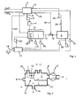
- the suction box is shown in Figure 2 in cross section.
- the purpose of the intake box is to safely supply penetrating flammable and / or toxic gases to the air conveying components of burner 4 and stack 8, and to reliably prevent the outflow of these gases into the surroundings of the intake box.
- Ansaugbox to safely control any possible internal leakage of components of the BZ system and thereby exclude hazards due to internal leakage. According to the expense of this is very low.
- This purpose is achieved by a meaningful subdivision of the element 7 into two regions (outer region: first chamber 1, inner region: second chamber 2). All combustible gases (anode residual gas, natural gas and venting of the process water reservoir) open into the inner housing (second chamber 2). All air streams / air connections (combustion air, intake air of the cathode fan and inlet of the heating air), on the other hand, discharge into the outer housing (first chamber 1). It is important that all air streams flow through the connection region 10, since this may contain, for example, a mass flow sensor for the combustion air, with which a certain burner control is realized.
- a special feature applies to the return port 20, via which the heating air is supplied to the intake box.
- This nozzle is continued within the outer housing of the intake as a pipe and this pipe ends coaxially within the intake of the inner housing (the second chamber 2), but still a sufficiently large cross-section of the intake of the inner housing remains free to blow with the fan. 5
- the intake box does not need to be opened for maintenance because it contains virtually no maintenance-intensive components (exception: air mass flow sensor, which, however, has a very long service life of generally> 10000 h).
- Another advantage results from the simple integration of a mass flow sensor 12 into the combustion air path (opening between the first and second chambers of the intake box), thereby enabling efficient combustion control.
- the second chamber 2 has a first and a second chamber portion between which a pressure loss generating diaphragm is arranged, wherein the first chamber portion a connecting piece for preheated air and the second chamber area the Connection 11 for the return of process gases and the supply port 6 for air and gas to the gas burner 4 has.
- the second chamber 2 is thus again subdivided, the pressure being higher in the first chamber area than in the second chamber area because of the intended aperture.
Landscapes
- Chemical & Material Sciences (AREA)
- Engineering & Computer Science (AREA)
- Chemical Kinetics & Catalysis (AREA)
- Combustion & Propulsion (AREA)
- Electrochemistry (AREA)
- General Chemical & Material Sciences (AREA)
- Life Sciences & Earth Sciences (AREA)
- Manufacturing & Machinery (AREA)
- Sustainable Development (AREA)
- Sustainable Energy (AREA)
- General Engineering & Computer Science (AREA)
- Mechanical Engineering (AREA)
- Organic Chemistry (AREA)
- Health & Medical Sciences (AREA)
- General Health & Medical Sciences (AREA)
- Inorganic Chemistry (AREA)
- Fuel Cell (AREA)
Priority Applications (2)
| Application Number | Priority Date | Filing Date | Title |
|---|---|---|---|
| PL06012825T PL1739779T3 (pl) | 2005-06-30 | 2006-06-22 | Urządzenie do wytwarzania energii cieplnej i elektrycznej |
| SI200630014T SI1739779T1 (sl) | 2005-06-30 | 2006-06-22 | Naprava za generiranje termalne in elektricne energije |
Applications Claiming Priority (1)
| Application Number | Priority Date | Filing Date | Title |
|---|---|---|---|
| DE102005030908A DE102005030908A1 (de) | 2005-06-30 | 2005-06-30 | Gerät zur Bereitstellung thermischer und elektrischer Energie |
Publications (2)
| Publication Number | Publication Date |
|---|---|
| EP1739779A1 true EP1739779A1 (fr) | 2007-01-03 |
| EP1739779B1 EP1739779B1 (fr) | 2007-11-21 |
Family
ID=36999777
Family Applications (1)
| Application Number | Title | Priority Date | Filing Date |
|---|---|---|---|
| EP06012825A Not-in-force EP1739779B1 (fr) | 2005-06-30 | 2006-06-22 | dispositif pour la génération d'energie thermique et electrique |
Country Status (6)
| Country | Link |
|---|---|
| EP (1) | EP1739779B1 (fr) |
| DE (2) | DE102005030908A1 (fr) |
| DK (1) | DK1739779T3 (fr) |
| ES (1) | ES2293613T3 (fr) |
| PL (1) | PL1739779T3 (fr) |
| SI (1) | SI1739779T1 (fr) |
Cited By (4)
| Publication number | Priority date | Publication date | Assignee | Title |
|---|---|---|---|---|
| AT511054A1 (de) * | 2010-10-27 | 2012-08-15 | Vaillant Group Austria Gmbh | Kondensatabscheider |
| EP2088638A3 (fr) * | 2008-02-07 | 2012-11-21 | Vaillant GmbH | Système de cellules combustibles à haute température doté d'un recyclage des gaz d'échappement |
| EP2634471A2 (fr) | 2012-03-01 | 2013-09-04 | Vaillant GmbH | Séparateur de condensat |
| CN111336510A (zh) * | 2020-02-28 | 2020-06-26 | 武汉理工大学 | 一种多孔介质燃烧和燃料电池多级耦合能源系统 |
Families Citing this family (2)
| Publication number | Priority date | Publication date | Assignee | Title |
|---|---|---|---|---|
| DE102006054056B4 (de) * | 2006-11-16 | 2009-06-25 | Siemens Ag | Brennstoffzellenvorrichtung mit einer Entwässerungseinrichtung |
| DE102021103540A1 (de) | 2021-02-16 | 2022-08-18 | Vaillant Gmbh | Verfahren und Anordnung zur Detektion von Wasserstoff aus Leckagen in einem Heizgerät, das mit Wasserstoff betreibbar ist |
Citations (3)
| Publication number | Priority date | Publication date | Assignee | Title |
|---|---|---|---|---|
| US20030096204A1 (en) * | 2001-11-20 | 2003-05-22 | Ingo Hermann | Catalytic combuster |
| EP1411573A2 (fr) * | 2002-10-16 | 2004-04-21 | Matsushita Electric Industrial Co., Ltd. | Brûleur, générateur d'hydrogène et système de génération électrique à pile à combustible |
| US20040081874A1 (en) * | 2001-05-04 | 2004-04-29 | Bayerische Motoren Werke Aktiengesellschaft | System comprising a fuel cell and a heat exchanger |
Family Cites Families (4)
| Publication number | Priority date | Publication date | Assignee | Title |
|---|---|---|---|---|
| US5980726A (en) * | 1998-05-05 | 1999-11-09 | Proton Energy Systems | Hydrogen electrochemical system environment |
| US6610431B1 (en) * | 2000-02-11 | 2003-08-26 | Plug Power Inc. | Method and apparatus for establishing a negative pressure inside an enclosure that houses a fuel cell system |
| DE10031238B4 (de) * | 2000-06-27 | 2005-02-03 | Ballard Power Systems Ag | Brennstoffzellensystem und Verfahren zum Betreiben des Brennstoffzellensystems |
| DE10160463B4 (de) * | 2001-12-10 | 2009-12-03 | Viessmann Werke Gmbh & Co Kg | Brennstoffzellenanlage |
-
2005
- 2005-06-30 DE DE102005030908A patent/DE102005030908A1/de not_active Ceased
-
2006
- 2006-06-22 DE DE502006000193T patent/DE502006000193D1/de active Active
- 2006-06-22 ES ES06012825T patent/ES2293613T3/es active Active
- 2006-06-22 DK DK06012825T patent/DK1739779T3/da active
- 2006-06-22 PL PL06012825T patent/PL1739779T3/pl unknown
- 2006-06-22 SI SI200630014T patent/SI1739779T1/sl unknown
- 2006-06-22 EP EP06012825A patent/EP1739779B1/fr not_active Not-in-force
Patent Citations (3)
| Publication number | Priority date | Publication date | Assignee | Title |
|---|---|---|---|---|
| US20040081874A1 (en) * | 2001-05-04 | 2004-04-29 | Bayerische Motoren Werke Aktiengesellschaft | System comprising a fuel cell and a heat exchanger |
| US20030096204A1 (en) * | 2001-11-20 | 2003-05-22 | Ingo Hermann | Catalytic combuster |
| EP1411573A2 (fr) * | 2002-10-16 | 2004-04-21 | Matsushita Electric Industrial Co., Ltd. | Brûleur, générateur d'hydrogène et système de génération électrique à pile à combustible |
Cited By (6)
| Publication number | Priority date | Publication date | Assignee | Title |
|---|---|---|---|---|
| EP2088638A3 (fr) * | 2008-02-07 | 2012-11-21 | Vaillant GmbH | Système de cellules combustibles à haute température doté d'un recyclage des gaz d'échappement |
| AT511054A1 (de) * | 2010-10-27 | 2012-08-15 | Vaillant Group Austria Gmbh | Kondensatabscheider |
| EP2634471A2 (fr) | 2012-03-01 | 2013-09-04 | Vaillant GmbH | Séparateur de condensat |
| DE102012003950A1 (de) | 2012-03-01 | 2013-09-05 | Vaillant Gmbh | Kondensatabscheider |
| CN111336510A (zh) * | 2020-02-28 | 2020-06-26 | 武汉理工大学 | 一种多孔介质燃烧和燃料电池多级耦合能源系统 |
| CN111336510B (zh) * | 2020-02-28 | 2021-04-02 | 武汉理工大学 | 一种多孔介质燃烧和燃料电池多级耦合能源系统 |
Also Published As
| Publication number | Publication date |
|---|---|
| EP1739779B1 (fr) | 2007-11-21 |
| ES2293613T3 (es) | 2008-03-16 |
| PL1739779T3 (pl) | 2008-03-31 |
| SI1739779T1 (sl) | 2008-02-29 |
| DE102005030908A1 (de) | 2007-01-04 |
| DK1739779T3 (da) | 2008-03-25 |
| DE502006000193D1 (de) | 2008-01-03 |
Similar Documents
| Publication | Publication Date | Title |
|---|---|---|
| DE102006020405B4 (de) | Brennstoffzellensystem und Verfahren zum Betreiben | |
| EP1739779B1 (fr) | dispositif pour la génération d'energie thermique et electrique | |
| DE102006020097B4 (de) | Brennstoffzellensystem und Verfahren zum Betreiben | |
| DE10297398T5 (de) | Abschaltverfahren für Brennstoffzellen-Brennstoffaufbereitungssystem | |
| DE102005013519B4 (de) | Nicht brennbare Abgasfreigabe für wasserstoffbetriebene Brennstoffzellen und Verfahren zum Ablassen von Anodenabgas | |
| WO1998054777A1 (fr) | Systeme de pile a combustible | |
| WO1992007392A1 (fr) | Procede et installation de generation simultanee d'energie electrique et d'energie mecanique | |
| EP0850494A1 (fr) | Procede d'actionnement d'un systeme de piles a combustible et systeme de piles a combustible permettant de mettre ledit procede en oeuvre | |
| DE10241970A1 (de) | Reformiervorrichtung und Brennstoffzellensystem | |
| WO1999033133A1 (fr) | Dispositif pour la conversion d'energie au moyen de piles a combustible avec generation integree de gaz d'hydrogene | |
| WO2017067966A2 (fr) | Agencement pour la recirculation cathodique d'une cellule à combustible et procédé de recirculation cathodique | |
| WO2013020647A1 (fr) | Systèmes de piles à combustible présentant un séparateur d'eau | |
| WO2019141602A1 (fr) | Système de pile à combustible muni d'une prise de pression moyenne associée à un compresseur ainsi qu'utilisation d'un système de pile à combustible de ce genre | |
| DE102006003740B4 (de) | Verfahren und System zum Betreiben einer Hochtemperaturbrennstoffzelle | |
| DE10157708B4 (de) | Brennstoffzellenanlage | |
| DE112007001313T5 (de) | Hybrid-Antriebssystem mit Brennstoffzelle und Motor | |
| AT505940B1 (de) | Hochtemperaturbrennstoffzellensystem mit abgasrückführung | |
| WO2004079846A2 (fr) | Systeme de cellules de combustible ayant au moins une cellule de combustible et un systeme generateur de gaz | |
| DE102015213917B4 (de) | Verfahren und System zum Ablassen von Anodenabgas einer Brennstoffzelle | |
| CH701210A1 (de) | Verfahren zum Betrieb eines Gasturbinenkraftwerkes mit Brennstoffzelle. | |
| DE102019217565A1 (de) | Brennstoffzellensystem und Verfahren zum Spülen eines Ausgleichsbehälters in einem Brennstoffzellensystem | |
| WO2020126414A1 (fr) | Dispositif de chauffage | |
| DE10324386B4 (de) | Brennstoffzellensystem | |
| DE102020110607A1 (de) | Konditionierungseinrichtung und Brennstoffzellenvorrichtung | |
| DE102021126708B3 (de) | Verfahren zum Starten einer Festoxidbrennstoffzellenvorrichtung sowie Brennstoffzellenfahrzeug |
Legal Events
| Date | Code | Title | Description |
|---|---|---|---|
| PUAI | Public reference made under article 153(3) epc to a published international application that has entered the european phase |
Free format text: ORIGINAL CODE: 0009012 |
|
| AK | Designated contracting states |
Kind code of ref document: A1 Designated state(s): AT BE BG CH CY CZ DE DK EE ES FI FR GB GR HU IE IS IT LI LT LU LV MC NL PL PT RO SE SI SK TR |
|
| AX | Request for extension of the european patent |
Extension state: AL BA HR MK YU |
|
| RIN1 | Information on inventor provided before grant (corrected) |
Inventor name: HESSE, WOLFGANG Inventor name: HECKMANN, JENS Inventor name: LORENZ, CHRISTIAN |
|
| GRAP | Despatch of communication of intention to grant a patent |
Free format text: ORIGINAL CODE: EPIDOSNIGR1 |
|
| 17P | Request for examination filed |
Effective date: 20070620 |
|
| AKX | Designation fees paid |
Designated state(s): AT BE BG CH CY CZ DE DK EE ES FI FR GB GR HU IE IS IT LI LT LU LV MC NL PL PT RO SE SI SK TR |
|
| GRAS | Grant fee paid |
Free format text: ORIGINAL CODE: EPIDOSNIGR3 |
|
| GRAA | (expected) grant |
Free format text: ORIGINAL CODE: 0009210 |
|
| AK | Designated contracting states |
Kind code of ref document: B1 Designated state(s): AT BE BG CH CY CZ DE DK EE ES FI FR GB GR HU IE IS IT LI LT LU LV MC NL PL PT RO SE SI SK TR |
|
| REG | Reference to a national code |
Ref country code: GB Ref legal event code: FG4D Free format text: NOT ENGLISH |
|
| REG | Reference to a national code |
Ref country code: CH Ref legal event code: NV Representative=s name: PATENTANWALTSBUERO DR. URS FALK |
|
| GBT | Gb: translation of ep patent filed (gb section 77(6)(a)/1977) |
Effective date: 20071121 |
|
| REG | Reference to a national code |
Ref country code: IE Ref legal event code: FG4D Free format text: LANGUAGE OF EP DOCUMENT: GERMAN |
|
| REG | Reference to a national code |
Ref country code: CH Ref legal event code: EP Ref country code: CH Ref legal event code: NV Representative=s name: PATENTANWALTSBUERO DR. URS FALK |
|
| REF | Corresponds to: |
Ref document number: 502006000193 Country of ref document: DE Date of ref document: 20080103 Kind code of ref document: P |
|
| REG | Reference to a national code |
Ref country code: GR Ref legal event code: EP Ref document number: 20070403592 Country of ref document: GR |
|
| REG | Reference to a national code |
Ref country code: RO Ref legal event code: EPE |
|
| REG | Reference to a national code |
Ref country code: SE Ref legal event code: TRGR |
|
| REG | Reference to a national code |
Ref country code: ES Ref legal event code: FG2A Ref document number: 2293613 Country of ref document: ES Kind code of ref document: T3 |
|
| REG | Reference to a national code |
Ref country code: DK Ref legal event code: T3 |
|
| REG | Reference to a national code |
Ref country code: PL Ref legal event code: T3 |
|
| ET | Fr: translation filed | ||
| REG | Reference to a national code |
Ref country code: HU Ref legal event code: AG4A Ref document number: E002788 Country of ref document: HU |
|
| PG25 | Lapsed in a contracting state [announced via postgrant information from national office to epo] |
Ref country code: LT Free format text: LAPSE BECAUSE OF FAILURE TO SUBMIT A TRANSLATION OF THE DESCRIPTION OR TO PAY THE FEE WITHIN THE PRESCRIBED TIME-LIMIT Effective date: 20071121 Ref country code: IS Free format text: LAPSE BECAUSE OF FAILURE TO SUBMIT A TRANSLATION OF THE DESCRIPTION OR TO PAY THE FEE WITHIN THE PRESCRIBED TIME-LIMIT Effective date: 20080321 Ref country code: LV Free format text: LAPSE BECAUSE OF FAILURE TO SUBMIT A TRANSLATION OF THE DESCRIPTION OR TO PAY THE FEE WITHIN THE PRESCRIBED TIME-LIMIT Effective date: 20071121 Ref country code: BG Free format text: LAPSE BECAUSE OF FAILURE TO SUBMIT A TRANSLATION OF THE DESCRIPTION OR TO PAY THE FEE WITHIN THE PRESCRIBED TIME-LIMIT Effective date: 20080221 Ref country code: FI Free format text: LAPSE BECAUSE OF FAILURE TO SUBMIT A TRANSLATION OF THE DESCRIPTION OR TO PAY THE FEE WITHIN THE PRESCRIBED TIME-LIMIT Effective date: 20071121 |
|
| PLBE | No opposition filed within time limit |
Free format text: ORIGINAL CODE: 0009261 |
|
| STAA | Information on the status of an ep patent application or granted ep patent |
Free format text: STATUS: NO OPPOSITION FILED WITHIN TIME LIMIT |
|
| PG25 | Lapsed in a contracting state [announced via postgrant information from national office to epo] |
Ref country code: PT Free format text: LAPSE BECAUSE OF FAILURE TO SUBMIT A TRANSLATION OF THE DESCRIPTION OR TO PAY THE FEE WITHIN THE PRESCRIBED TIME-LIMIT Effective date: 20080421 |
|
| PGFP | Annual fee paid to national office [announced via postgrant information from national office to epo] |
Ref country code: PL Payment date: 20080509 Year of fee payment: 4 |
|
| REG | Reference to a national code |
Ref country code: IE Ref legal event code: FD4D |
|
| 26N | No opposition filed |
Effective date: 20080822 |
|
| PG25 | Lapsed in a contracting state [announced via postgrant information from national office to epo] |
Ref country code: IE Free format text: LAPSE BECAUSE OF FAILURE TO SUBMIT A TRANSLATION OF THE DESCRIPTION OR TO PAY THE FEE WITHIN THE PRESCRIBED TIME-LIMIT Effective date: 20071121 |
|
| PG25 | Lapsed in a contracting state [announced via postgrant information from national office to epo] |
Ref country code: MC Free format text: LAPSE BECAUSE OF NON-PAYMENT OF DUE FEES Effective date: 20080630 |
|
| PG25 | Lapsed in a contracting state [announced via postgrant information from national office to epo] |
Ref country code: EE Free format text: LAPSE BECAUSE OF FAILURE TO SUBMIT A TRANSLATION OF THE DESCRIPTION OR TO PAY THE FEE WITHIN THE PRESCRIBED TIME-LIMIT Effective date: 20071121 |
|
| PG25 | Lapsed in a contracting state [announced via postgrant information from national office to epo] |
Ref country code: CY Free format text: LAPSE BECAUSE OF FAILURE TO SUBMIT A TRANSLATION OF THE DESCRIPTION OR TO PAY THE FEE WITHIN THE PRESCRIBED TIME-LIMIT Effective date: 20071121 |
|
| PGFP | Annual fee paid to national office [announced via postgrant information from national office to epo] |
Ref country code: DK Payment date: 20090625 Year of fee payment: 4 Ref country code: ES Payment date: 20090529 Year of fee payment: 4 Ref country code: RO Payment date: 20090602 Year of fee payment: 4 Ref country code: SI Payment date: 20090528 Year of fee payment: 4 |
|
| PGFP | Annual fee paid to national office [announced via postgrant information from national office to epo] |
Ref country code: AT Payment date: 20090629 Year of fee payment: 4 Ref country code: CZ Payment date: 20090529 Year of fee payment: 4 Ref country code: SE Payment date: 20090618 Year of fee payment: 4 Ref country code: TR Payment date: 20090602 Year of fee payment: 4 |
|
| PGFP | Annual fee paid to national office [announced via postgrant information from national office to epo] |
Ref country code: BE Payment date: 20090622 Year of fee payment: 4 Ref country code: SK Payment date: 20090601 Year of fee payment: 4 |
|
| PGFP | Annual fee paid to national office [announced via postgrant information from national office to epo] |
Ref country code: HU Payment date: 20090610 Year of fee payment: 4 |
|
| PG25 | Lapsed in a contracting state [announced via postgrant information from national office to epo] |
Ref country code: LU Free format text: LAPSE BECAUSE OF NON-PAYMENT OF DUE FEES Effective date: 20080622 |
|
| PGFP | Annual fee paid to national office [announced via postgrant information from national office to epo] |
Ref country code: FR Payment date: 20100622 Year of fee payment: 5 |
|
| PGFP | Annual fee paid to national office [announced via postgrant information from national office to epo] |
Ref country code: NL Payment date: 20100528 Year of fee payment: 5 |
|
| PGFP | Annual fee paid to national office [announced via postgrant information from national office to epo] |
Ref country code: DE Payment date: 20100515 Year of fee payment: 5 Ref country code: GB Payment date: 20100614 Year of fee payment: 5 Ref country code: IT Payment date: 20100628 Year of fee payment: 5 |
|
| BERE | Be: lapsed |
Owner name: VIESSMANN WERKE G.M.B.H. & CO. KG Effective date: 20100630 |
|
| REG | Reference to a national code |
Ref country code: DK Ref legal event code: EBP Ref country code: CH Ref legal event code: PL |
|
| EUG | Se: european patent has lapsed | ||
| PG25 | Lapsed in a contracting state [announced via postgrant information from national office to epo] |
Ref country code: CZ Free format text: LAPSE BECAUSE OF NON-PAYMENT OF DUE FEES Effective date: 20100622 |
|
| REG | Reference to a national code |
Ref country code: SI Ref legal event code: KO00 Effective date: 20110127 |
|
| REG | Reference to a national code |
Ref country code: SK Ref legal event code: MM4A Ref document number: E 3053 Country of ref document: SK Effective date: 20100622 |
|
| PG25 | Lapsed in a contracting state [announced via postgrant information from national office to epo] |
Ref country code: LI Free format text: LAPSE BECAUSE OF NON-PAYMENT OF DUE FEES Effective date: 20080630 Ref country code: CH Free format text: LAPSE BECAUSE OF NON-PAYMENT OF DUE FEES Effective date: 20080630 |
|
| PG25 | Lapsed in a contracting state [announced via postgrant information from national office to epo] |
Ref country code: HU Free format text: LAPSE BECAUSE OF NON-PAYMENT OF DUE FEES Effective date: 20100623 Ref country code: LI Free format text: LAPSE BECAUSE OF NON-PAYMENT OF DUE FEES Effective date: 20100630 Ref country code: CH Free format text: LAPSE BECAUSE OF NON-PAYMENT OF DUE FEES Effective date: 20100630 |
|
| PG25 | Lapsed in a contracting state [announced via postgrant information from national office to epo] |
Ref country code: SK Free format text: LAPSE BECAUSE OF NON-PAYMENT OF DUE FEES Effective date: 20100622 Ref country code: SI Free format text: LAPSE BECAUSE OF NON-PAYMENT OF DUE FEES Effective date: 20100623 |
|
| PG25 | Lapsed in a contracting state [announced via postgrant information from national office to epo] |
Ref country code: BE Free format text: LAPSE BECAUSE OF NON-PAYMENT OF DUE FEES Effective date: 20100630 Ref country code: GR Free format text: LAPSE BECAUSE OF NON-PAYMENT OF DUE FEES Effective date: 20110104 |
|
| REG | Reference to a national code |
Ref country code: ES Ref legal event code: FD2A Effective date: 20110715 |
|
| PG25 | Lapsed in a contracting state [announced via postgrant information from national office to epo] |
Ref country code: ES Free format text: LAPSE BECAUSE OF NON-PAYMENT OF DUE FEES Effective date: 20110705 |
|
| PG25 | Lapsed in a contracting state [announced via postgrant information from national office to epo] |
Ref country code: DK Free format text: LAPSE BECAUSE OF NON-PAYMENT OF DUE FEES Effective date: 20100630 Ref country code: RO Free format text: LAPSE BECAUSE OF NON-PAYMENT OF DUE FEES Effective date: 20100622 |
|
| PG25 | Lapsed in a contracting state [announced via postgrant information from national office to epo] |
Ref country code: ES Free format text: LAPSE BECAUSE OF NON-PAYMENT OF DUE FEES Effective date: 20100623 |
|
| REG | Reference to a national code |
Ref country code: NL Ref legal event code: V1 Effective date: 20120101 |
|
| GBPC | Gb: european patent ceased through non-payment of renewal fee |
Effective date: 20110622 |
|
| PG25 | Lapsed in a contracting state [announced via postgrant information from national office to epo] |
Ref country code: IT Free format text: LAPSE BECAUSE OF NON-PAYMENT OF DUE FEES Effective date: 20110622 Ref country code: AT Free format text: LAPSE BECAUSE OF NON-PAYMENT OF DUE FEES Effective date: 20110622 Ref country code: PL Free format text: LAPSE BECAUSE OF NON-PAYMENT OF DUE FEES Effective date: 20100622 |
|
| REG | Reference to a national code |
Ref country code: PL Ref legal event code: LAPE |
|
| REG | Reference to a national code |
Ref country code: AT Ref legal event code: MM01 Ref document number: 379296 Country of ref document: AT Kind code of ref document: T Effective date: 20110622 |
|
| REG | Reference to a national code |
Ref country code: FR Ref legal event code: ST Effective date: 20120229 |
|
| REG | Reference to a national code |
Ref country code: DE Ref legal event code: R119 Ref document number: 502006000193 Country of ref document: DE Effective date: 20120103 |
|
| PG25 | Lapsed in a contracting state [announced via postgrant information from national office to epo] |
Ref country code: DE Free format text: LAPSE BECAUSE OF NON-PAYMENT OF DUE FEES Effective date: 20120103 Ref country code: FR Free format text: LAPSE BECAUSE OF NON-PAYMENT OF DUE FEES Effective date: 20110630 |
|
| PG25 | Lapsed in a contracting state [announced via postgrant information from national office to epo] |
Ref country code: NL Free format text: LAPSE BECAUSE OF NON-PAYMENT OF DUE FEES Effective date: 20120101 |
|
| PG25 | Lapsed in a contracting state [announced via postgrant information from national office to epo] |
Ref country code: GB Free format text: LAPSE BECAUSE OF NON-PAYMENT OF DUE FEES Effective date: 20110622 |
|
| PG25 | Lapsed in a contracting state [announced via postgrant information from national office to epo] |
Ref country code: SE Free format text: LAPSE BECAUSE OF NON-PAYMENT OF DUE FEES Effective date: 20100623 |
|
| PG25 | Lapsed in a contracting state [announced via postgrant information from national office to epo] |
Ref country code: TR Free format text: LAPSE BECAUSE OF NON-PAYMENT OF DUE FEES Effective date: 20100622 |
|
| REG | Reference to a national code |
Ref country code: GR Ref legal event code: ML Ref document number: 20070403592 Country of ref document: GR Effective date: 20110104 |