EP1739203A1 - Titanium treatment to minimize fretting - Google Patents
Titanium treatment to minimize fretting Download PDFInfo
- Publication number
- EP1739203A1 EP1739203A1 EP06253302A EP06253302A EP1739203A1 EP 1739203 A1 EP1739203 A1 EP 1739203A1 EP 06253302 A EP06253302 A EP 06253302A EP 06253302 A EP06253302 A EP 06253302A EP 1739203 A1 EP1739203 A1 EP 1739203A1
- Authority
- EP
- European Patent Office
- Prior art keywords
- titanium
- carbon
- dovetail
- compressor disk
- carburized
- Prior art date
- Legal status (The legal status is an assumption and is not a legal conclusion. Google has not performed a legal analysis and makes no representation as to the accuracy of the status listed.)
- Ceased
Links
- 0 CCCC1CC(C)(*)CCC1 Chemical compound CCCC1CC(C)(*)CCC1 0.000 description 1
Images


Classifications
-
- C—CHEMISTRY; METALLURGY
- C23—COATING METALLIC MATERIAL; COATING MATERIAL WITH METALLIC MATERIAL; CHEMICAL SURFACE TREATMENT; DIFFUSION TREATMENT OF METALLIC MATERIAL; COATING BY VACUUM EVAPORATION, BY SPUTTERING, BY ION IMPLANTATION OR BY CHEMICAL VAPOUR DEPOSITION, IN GENERAL; INHIBITING CORROSION OF METALLIC MATERIAL OR INCRUSTATION IN GENERAL
- C23C—COATING METALLIC MATERIAL; COATING MATERIAL WITH METALLIC MATERIAL; SURFACE TREATMENT OF METALLIC MATERIAL BY DIFFUSION INTO THE SURFACE, BY CHEMICAL CONVERSION OR SUBSTITUTION; COATING BY VACUUM EVAPORATION, BY SPUTTERING, BY ION IMPLANTATION OR BY CHEMICAL VAPOUR DEPOSITION, IN GENERAL
- C23C8/00—Solid state diffusion of only non-metal elements into metallic material surfaces; Chemical surface treatment of metallic material by reaction of the surface with a reactive gas, leaving reaction products of surface material in the coating, e.g. conversion coatings, passivation of metals
- C23C8/06—Solid state diffusion of only non-metal elements into metallic material surfaces; Chemical surface treatment of metallic material by reaction of the surface with a reactive gas, leaving reaction products of surface material in the coating, e.g. conversion coatings, passivation of metals using gases
- C23C8/08—Solid state diffusion of only non-metal elements into metallic material surfaces; Chemical surface treatment of metallic material by reaction of the surface with a reactive gas, leaving reaction products of surface material in the coating, e.g. conversion coatings, passivation of metals using gases only one element being applied
- C23C8/20—Carburising
Definitions
- the present invention is directed to a method for surface treating titanium and titanium alloys.
- the invention is drawn to surface treating gas turbine engine components.
- a gas turbine engine generally operates by pressurizing air in a compressor and mixing the air with fuel in a combustor.
- the air/fuel mixture is ignited and hot combustion gasses result, which flow downstream through a turbine section.
- the compressor typically includes compressor disks having airfoils dovetailed into the compressor disk.
- the compressor may include multiple disks, each having a plurality of airfoils.
- Each of the compressor disk and the airfoils typically contain titanium, usually in the form of a titanium alloy.
- the titanium-to-titanium surface contact is susceptible to fretting wear and fretting fatigue. Fretting is the degradation of the surface usually resulting from localized adhesion between the contacting surfaces as the surfaces slide against each other.
- fretting is magnified in systems having a titanium-containing surface contacting another titanium-containing surface.
- the fretting fatigue may result from movement of the dovetail of the airfoil within the slot in the compressor disk. As the disk rotates at a higher rotational speed, the centrifugal force on the airfoil urges the blade to move outward and slip along the surface of the dovetail.
- a second source of movement resulting in fretting fatigue in the dovetail system is the vibration from the airfoil. Aerodynamic forces may result in oscillation of the airfoil within the dovetail slot. The oscillation translates to high frequency vibration through the airfoil to the dovetail portion of the airfoil. As the airfoil vibrates, the surface of the dovetail section of the airfoil slides against the surface of the slot of the compressor disk, resulting in fretting fatigue.
- the titanium dovetail surface of the airfoil may be shot-peened to create compressive stress in the airfoil surface.
- the increased compressive stress on the surface results in increased hardness, which reduces the adhesion between surfaces thereby reducing the fretting fatigue and wear.
- the shot-peening process requires expensive equipment, additional processing steps and may result in surfaces having variability in roughness and dimensional accuracy.
- the shot-peened surface provides insufficient resistance to fretting fatigue and wear.
- a coating of CuNiln, aluminum bronze or a MoS 2 lubricant may be coated onto the airfoil's dovetail surface to provide a surface that experiences less adhesion between surfaces.
- lubricants such as MoS 2 provides some protection from localized adhesion, but the lubricants alone, without additional coating layers, fail to provide sufficient resistance to fretting fatigue and wear.
- Carburizing is a method that has been used to increase hardness of a surface. It is a well-known method for hardening steel surface to improve wear properties. Known carburizing methods take place at high temperatures, including temperatures of greater than about 1700 °F (927 °C). High temperature carburization methods suffer from the drawback that the method requires expensive, specialized equipment, capable of operating under high temperatures. High-temperature thermal treatments of blade dovetails and disks preclude use of conventional carburizing practices.
- the present invention includes a method for surface treating a gas turbine engine component comprising a titanium or titanium alloy.
- the method includes providing a gas turbine engine component having a titanium-containing surface.
- the component is heated to a temperature sufficient to diffuse carbon into the titanium and below 1000 °F.
- the surface is contacted with a carbon-containing gas to diffuse carbon into the surface to form carbides and/or interstitial carbon.
- the carbon-containing surface may be coated with a lubricant to further reduce the coefficient of friction between surfaces.
- the coefficient of friction between the surface and another titanium-containing surface is preferably less than about 0.6.
- a metallic surface comprising titanium is carburized, under controlled conditions, using carbon-containing gases, such as methane, propane, ethylene or acetylene gas or combinations thereof as the carburizing agent in order to form stable carbides and/or interstitial carbon at a controlled, preselected distance below the surface and/or diffuse the carbon interstitially in the titanium matrix.
- carbon-containing gases such as methane, propane, ethylene or acetylene gas or combinations thereof
- Another embodiment of the present invention includes a gas turbine engine component having a titanium-containing compressor disk.
- the compressor disk including a surface containing carbides and/or interstitial carbon and a lubricant coating thereon having a binder and a friction modifier.
- the binder preferably including titanium oxide and the friction modifier preferably including tungsten disulfide.
- Another embodiment of the present invention includes a gas turbine engine component having a titanium-containing airfoil.
- the airfoil including one or more surfaces that contain carbides and/or interstitial carbon and a lubricant coating thereon.
- titanium alloys may include other carbide forming elements, such as, for example, vanadium.
- alloys containing vanadium treated according to the present invention may include vanadium carbides, in addition to titanium carbides.
- One advantage of an embodiment according to the present invention is that the method according to the present invention decreases the susceptibility of the surface to fretting.
- Another advantage of an embodiment of the present invention is that the method provides a hardened surface having carbides and/or interstitial carbon, which resist corrosion.
- Another advantage of an embodiment of the present invention that the method according to the present invention provides a hardened surface that is resistant to erosion.
- Another advantage of an embodiment of the present invention is that the carburization takes place at a low temperature, below 1000 °F, which reduces the cost of equipment required to produce the carburized zone.
- Another advantage of an embodiment of the present invention is that the surfaces subjected to fretting wear and fatigue may be replaced less often, decreasing servicing cost and reliability.
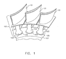
- FIG. 1 is a cutaway view of a section of a high-pressure compressor for a turbine engine according to the present invention.
- the compressor includes a plurality of blades 100.
- the blades 100 include an airfoil 101 and a dovetail 103, which is positioned within dovetail slots 105 in a compressor disk 107.
- the dovetail 103 of the blade 100 retains the blade 100 during operation of the gas turbine engine.
- the blade 100 and the compressor disk 107 according to the invention include titanium and have one or more surfaces that are in frictional contact that are carburized to produce a surface having a carburized zone 401 (see FIGs. 4-9).
- FIG. 1 illustrates a compressor disk 107 and blade 100
- any titanium or titanium alloy surface may be treated according to an embodiment of the invention
- FIG. 2 shows a perspective view of a compressor disk 107 according to an embodiment of the present invention, wherein FIG. 2 shows dovetail slots 105 into which the dovetail 103 section of blades 100 are positioned.
- the surfaces of dovetail slots 105 are subjected to sliding friction with dovetail 103 of blades 100 and are susceptible to fretting.
- the surface of compressor disk 107 includes a carburized zone 401 and, optionally, a lubricant coating 601 (see FIGs. 4-9).
- FIG. 3 shows a cutaway view of a blade 100 positioned in dovetail slots 105 of compressor disk 107 according to an embodiment of the present invention. At least a portion of the surface of slot 105 is in frictional contact with at least a portion of the surface of dovetail 103. As the gas turbine engine operates, the centrifugal forces provided by the variation of the rotational speed of the compressor disk 107 results in rubbing between the surface of the dovetail 103 and the surface of the dovetail slot 105 in the compressor disk 107.
- the coefficient of friction between the surfaces of the dovetail 103 and the surface of the slot 105 are preferably maintained below 0.6. Preferably, the coefficient of friction is below 0.4. More preferably, the coefficient of friction is below 0.2.
- the lowering of the coefficient of friction is a result of the hardened surface resulting from the carburization.
- the carburized zone 401 (see FIGs. 4-9) has a greater hardness than an untreated titanium-containing surface.
- the application of a lubricant coating 601 (see FIGs. 6-9) further decreases the coefficient of friction.
- the additional lowering of the coefficient of friction is a result of the tribological properties of components of the lubricant coating 601.
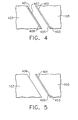
- FIGs. 4-9 shows enlarged cross-sections taken from region 301 from FIG. 3 illustrating alternate coating arrangements according to the present invention.
- the cross sections in FIGs 4-9 each include a dovetail slot 105 of compressor disk 107 and dovetail 103 in frictional contact.
- the surface of the dovetail slot 105 of compressor disk 107 and the surface of the dovetail 103 form opposed surfaces onto which a carburized zone 401 and lubricant coating 601 may be applied.
- FIGs. 4-9 illustrate alternate locations for placement of the carburized zone 401 and lubricant coating 601.
- Lubricant coating 601 may be disposed on the dovetail 103, the dovetail slot 105 of the compressor disk 107, a carburized dovetail 103 or a carburized dovetail slot 105 of the compressor disk 107 or on a combination thereof.
- the optional coating 601 may include, but is not limited to, graphite, CuNiln, aluminum bronze or MoS 2 .
- a space has been shown between the coatings on the compressor disk 107 and the dovetail 103 in FIGs. 4-9, the space is merely illustrative of the placement of the coatings.
- the coating systems on each of the surface of the dovetail slot 105 and the dovetail 103 are in frictional contact, wherein the surfaces are adjacent and experience sliding or rubbing.
- FIGs. 4-9 are shown having thicknesses of the carburized zone 401 and lubricant coating 601 that is merely illustrative and does not indicate the relative thickness of the carburization zone 401 or the lubricant coating
- FIG. 4 shows an enlarged cross-section taken from region 301 from FIG. 3 showing an embodiment of the present invention.
- FIG. 4 includes dovetail 103 interfacing with the dovetail slot 105 of compressor disk 107.
- Surface 403 of the dovetail slot 105 of compressor disk 107 and surface 409 of dovetail 103 have each been carburized and include carburized zone 401.
- Surface 405 includes the surface of the carburization coating 401 on the compressor disk and is in frictional contact with surface 407.
- Surface 407 is the surface of the carburized zone 401 on surface 409 of dovetail 103.
- carburized zone 401 is provided on both the dovetail and compressor disk 107 providing hardened sliding surfaces that slide against each other providing desirable tribological properties.
- the combination of the hard, wear resistant carburized zone 401 sliding against each other provide a low coefficient of friction and increased fretting resistance.
- FIG. 5 shows an enlarged cross-section taken from region 301 from FIG. 3 showing an alternate embodiment of the present invention.
- FIG. 5 includes dovetail 103, dovetail slot 105 of compressor disk 107, as shown in FIG. 4.
- Surface 403 of the dovetail slot 105 of compressor disk 107 has been carburized and includes carburized zone 401.
- Surface 405 includes the surface of the carburized zone 401 on the dovetail slot 105 on compressor disk 107 and is in frictional contact with surface 409 of dovetail 103.
- the embodiment shown in FIG. 5 has the benefit that the carburized zone 401 is coated only on the compressor disk 107. Therefore, the application of carburized zone 401 requires less equipment and labor than applying carburized zone 401 to both the compressor disk 107 and the blade 100.
- FIG. 6 shows an enlarged cross-section taken from region 301 from FIG. 3 showing an alternate embodiment of the present invention.
- FIG. 6 includes dovetail 103, dovetail slot 105 of compressor disk 107, as shown in FIG. 4.
- Surface 403 of the dovetail slot 105 of compressor disk 107 has been carburized and includes carburized zone 401.
- Lubricant coating 601 is disposed on surface 405 of the carburized zone 401.
- Surface 603 of lubricant coating 601 is in frictional contact with surface 409 of dovetail 103.
- the embodiment shown in FIG. 6 has the benefit that the carburized zone 401 and lubricant coating 601 are coated only on the compressor disk 107.
- carburized zone 401 requires less equipment and labor than producing carburized zone 401 to both the dovetail slot of compressor disk 107 and the airfoil.
- the compressor disk 107 is protected from fretting damage, whereas the less expensive, easier to replace blade 100 has not been specially treated.
- the carburized zone 401 and lubricant coating 601 provide protection of the compressor disk 107 and blade 100 system, while not adding expense to the blades 100.
- FIG. 7 shows an enlarged cross-section taken from region 301 from FIG. 3 showing an alternate embodiment of the present invention.
- FIG. 7 includes dovetail 103, dovetail slot 105 of compressor disk 107, as shown in FIG. 4.
- Surface 409 of dovetail 103 of blade 100 has been carburized and includes carburized zone 401.
- Lubricant coating 601 is disposed on surface 407 of the carburized zone 401.
- Surface 603 of lubricant coating 601 is in frictional contact with surface 403 of the dovetail slot 105 of compressor disk 107.
- the embodiment shown in FIG. 7 has the benefit that the carburized zone 401 and lubricant coating 601 are coated only on dovetail 103 of blade 100.
- Coating only the dovetail 103 has the advantage that the blades 100 may easily be removed from the compressor disk 107 in order to be coated according to the present invention.
- the compressor disk 107 and blade 100 system of the present invention may be retrofitted into existing gas turbine engines by removing the blades 100 from the compressor disks 107, wherein the removal of the compressor disk 107 from the engine is not necessary.
- the dovetail 103 may provide the resistance to fretting without requiring the removal or replacement of the compressor disks 107 from the engine.
- FIG. 8 shows an enlarged cross-section taken from region 301 from FIG. 3 showing an alternate embodiment of the present invention.
- FIG. 8 includes dovetail 103, dovetail slot 105 of compressor disk 107, as shown in FIG. 4.
- Surface 403 of the dovetail slot 105 of compressor disk 107 has been carburized and includes carburized zone 401.
- Lubricant coating 601 is disposed on surface 409 of the dovetail 103.
- Surface 603 of lubricant coating 601 is in frictional contact with surface 405 of carburized zone 401 on the dovetail slot 105 of compressor disk 107.
- the embodiment shown in FIG. 8 has the benefit that the carburized zone 401 is present on the dovetail slot 105 of compressor disk 107 protecting the surface from fretting.
- the dovetail 103 of blade 100 is coated with lubricant coating 601.
- the lubricant coating 601 may be easily replaced by removing the blade 100 from compressor disk 107 and coating the lubricant coating 601 onto dovetail 103 of blade 100.
- the lubricant coating 601 in this embodiment permits the easy replacement of the lubricant coating 601 in the event that the lubricant coating 601 wears thin or wears completely off.
- FIG. 9 shows an enlarged cross-section taken from region 301 from FIG. 3 showing an alternate embodiment of the present invention.
- FIG. 9 includes dovetail 103, dovetail slot 105 of compressor disk 107, as shown in FIG. 4.
- Surface 403 of dovetail slot 105 of compressor disk 107 has been carburized and includes carburized zone 401.
- Surface 409 of dovetail 103 of blade 100 has also been carburized and includes carburized zone 401.
- Lubricant coating 601 is disposed on surface 407 of the carburized coatings 401, both on the dovetail 103 of blade 100 and on the dovetail slot 105 of compressor disk 107.
- the present invention also provides methods for carburizing a metallic surface comprising titanium.
- titanium-containing blade 100 or compressor disk 107 for use in a gas turbine engine is subjected to carburizing.
- the surface for coating according to the present invention is preferably a titanium alloy.
- the titanium alloy is Ti-6-4 titanium alloy having about 6 wt% aluminum, about 4 wt% vanadium and balance essentially titanium.
- suitable alloys for use in the blade 100 include, but are not limited to Ti-4-4-2 (about 4 wt% aluminum, about 4 wt% molybdenum, and about 2 wt% tin), Ti-6-2-4-2 (about 6 wt% aluminum, about 2 wt% molybdenum, about 4 wt% zirconium and about 2 wt% tin), Ti-8-1-1 (about 8 wt% aluminum, about 1 wt% molybdenum, and about 1 wt% vanadium).
- suitable alloys for use in the compressor disk 107 include, but are not limited to Ti-17 (about 5 wt% aluminum, about 4 wt% chromium, about 4 wt% molybdenum, about 2 wt% zirconium and about 2 wt% tin) and Ti-6-2-4-2 (about 6 wt% aluminum, about 2 wt% molybdenum, about 4 wt% zirconium and about 2 wt% tin).
- Other suitable alloys for fabrication of compressor disk 107 for use with blades 100 having a carburized zone 401 include, but are not limited to, nickel-based alloys, such as INCONEL® 718, R-95, or R-88.
- INCONEL® is a federally registered trademark owned by Huntington Alloys Corporation of Huntington, West Virginia.
- the composition of INCONEL® 718 is well-known in the art and is a designation for a nickel-based superalloy comprising about 18 weight percent chromium, about 19 weight percent iron, about 5 weight percent niobium + tantalum, about 3 weight percent molybdenum, about 0.9 weight percent titanium, about 0.5 weight percent aluminum, about 0.05 weight percent carbon, about 0.009 weight percent boron, a maximum of about 1 weight percent cobalt, a maximum of about 0.35 weight percent manganese, a maximum of about 0.35 weight percent silicon, a maximum of about 0.1 weight percent copper, and the balance nickel.
- R-95 includes a composition having about 8% cobalt, about 13% chromium, about 3.5% molybdenum, about 3.5% tungsten, about 3.5% aluminum, about 2.5% titanium, about 3.5% niobium, about 0.03% boron, about 0.03% carbon, about 0.03% zirconium, up to about 0.01% vanadium, up to about 0.3% hafnium, up to about 0.01% yttrium and the balance essentially nickel.
- R-88 includes a composition having about 13% cobalt, about 16% chromium, about 4% molybdenum, about 4% tungsten, about 2% aluminum, about 3.7% titanium, about 0.75% niobium, about 0.4% zirconium, about 0.06% carbon, about 0.010% boron and the balance essentially nickel.
- a metallic surface comprising titanium is carburized, under controlled conditions, using carbon-containing gases, such as methane, propane, ethylene gas, acetylene, carbon dioxide, carbon monoxide or combinations thereof as the carburizing agent in order to form stable carbides at a controlled, preselected distance below the surface.
- the carbides may include titanium carbides, vanadium carbides and mixtures thereof, including titanium-vanadium carbide complexes. These gases may be mixed in combination, or non-reactive gases such as argon, helium, or hydrogen may be added in order to control the reactivity of the carburizing gases.
- the titanium carbide formed in the surface hardens the surface, providing a reduced coefficient of friction, and reducing fretting.
- concentration and/or presence of interstitial carbon in the titanium matrix can also be a controlling factor in the process.
- the present invention may include a step of cleaning the article surface.
- Cleaning the article surface entails removing a portion or substantially all oxides from the surface of the substrate and preventing the reformation of oxides from the surface that is to be carburized.
- the surface to be carburized is preferably free of oxides.
- Removing oxides can be accomplished by mechanical or chemical methods that do not damage or otherwise adversely affect the substrate surface.
- the mechanical or chemical oxide removal methods may be any oxide removal methods known in the art, including but not limited to grit blasting or chemical etching. After such cleaning, the surfaces may be cleaned with a suitable solvent, while avoiding the formation of oxides. While oxides are to be avoided, it may be desirable to mask portions of the surface in order to prevent these portions from being carburized.
- the carburizing of the entire compressor disk 107 and/or blade 100 may provide the compressor disk 107 and blade 100 with desirable surface properties.
- an airfoil 101 portion of a blade 100 having a carburized zone 401 may be resistant to corrosion due to the presence of carbides and/or interstitial carbon at the surface. The resistance to corrosion is desirable for airfoils 101 and compressor disks 107 due to the fact that the airfoils 101 and compressor disks may contact air that includes water and/or corrosion accelerators, such as salt.
- the carburizing of the entire compressor disk 107 and/or blade 100 may provide the compressor disk 107 and blade 100 with protection against erosion due to the hardened, wear-resistant carburized zone 401.
- the resistance to erosion is desirable, for example, for airfoils 101 and compressor disks 107 due to contact with air that includes abrasive material, such as sand or dirt. Therefore, the method of the present invention may advantageously be utilized to coat the entire compressor disk 107 and/or blade 100.
- the cleaned article is then loaded into a furnace suitable for performing the carburization process.
- Suitable furnaces include vacuum furnaces or furnaces that can maintain a controlled atmosphere.
- the furnace is heated to a temperature sufficient to permit the diffusion of carbon into titanium, and less than about 1000°F (538 °C).
- the furnace is heated to about 750°F (400 °C).
- the carburizing gases may be introduced into the furnace by any method that prevents the introduction of oxygen.
- introduction of the carburizing gases should be such that the concentration of the carbon-containing gas may be varied.
- the atmosphere When maintaining a controlled atmosphere, the atmosphere must be non-oxidizing, as oxidation of the article surface and reaction of the carburizing gas with oxygen must be prevented during heat-up to the carburizing temperature and during carburizing.
- the carburizing gas methane, propane, ethylene or acetylene
- these carburizing gases may be introduced below the carburizing temperature with hydrogen or to gradually replace hydrogen, but should not be added at a temperature or in a volume that will result in excessive soot formation.
- the carburizing gas is provided to ensure sufficient carbon is present at the article surface for desired carburization so that carbon is diffused and is formed in a layer having titanium carbide and/or carbon diffused interstitially.
- the carbides and/or interstitial carbon increase the hardness of the surface and reduce fretting. As the hardness of the surface increases, the incident of localized adhesion between titanium-containing surfaces is reduced. The reduction in localized adhesion results in a greater resistance to fretting fatigue and wear.
- the duration, temperature and concentration of carbon in the carbon-containing gas of the carburization process may be controlled to limit the depth of carbide layer formation.
- the amount of carbon present in the layer is sufficient to provide the titanium-containing surface with a reduced susceptibility to fretting when in contact with other titanium-containing surfaces.
- the amount of carbon present in the carburized zone 401 includes an amount of carbon that is greater than the carbon present in a conventional carburized surface that was carburized at high temperatures, such as temperatures greater than about 1000 °F.
- Carburization is continued until the desired carburization depth is reached at which time the operation is stopped by introducing an inert gas to the furnace.
- Carburization depth is temperature, time and concentration dependent, wherein the resultant depth may be governed by the laws of mass transfer and, in particular, Fick's first and second law of diffusion.
- Carburization ceases when the surface temperature of the article is less than the temperature at which carbon diffuses.
- the depth of the carburization varies based upon a variety of factors including the time the article is exposed to the carbon-containing gas, the concentration of the carbon in the carbon-containing gas and the temperature of the article.
- a preferable depth for the carburization coating 401 is up to about 0.01 inches. More preferably up to about 0.001 inches.
- the carburization process according to the invention takes place for a time up to about 1500 hours for the desired carburization coating 401 depth to be achieved.
- the carburization takes place for a time up to about 1000 hours.
- the carburization process is completed by purging the chamber of the carburizing gas. This can be accomplished by stopping the flow of the carburizing gas and introducing an inert gas, nitrogen or hydrogen into the chamber. This also serves to cool the article. Any masking present on the surface may be removed.
- gas flow rate which determines partial gas pressure, temperature, type of furnace, working zone size, work load and time.
- the work load may comprise a plurality of articles, can be removed from the work zone.
- Any optional masking may be removed before or after the application of the optional lubricant coating 601.
- Masking may be removed by any suitable means that does not adversely affect the substrate surface, such as chemical stripping, mechanical means such as blasting, or other known methods consistent with the masking material.
- Compressor disks 107 and blades 100 that comprise titanium are particularly suitable for use with the method of the present invention.
- Carburized compressor disks 107 and/or dovetails 103 coated with a lubricant coating 601 provide desirable tribological properties.
- the present invention utilizes the combination of the relatively hard carburized zone 401 in combination with a relatively soft, lubricious lubricant coating 601, which may be placed on surfaces susceptible to wear. Suitable surfaces include component surfaces within a compressor of a gas turbine engine.
- the carburized zone 401 reduces the coefficient of friction between the compressor disk 107 and blade 100.
- the lubricant coating 601 further reduces the coefficient of friction between the compressor disk 107 and the blade 100, reducing localized adhesion between the surfaces, thereby reducing fretting.
- the coefficient of friction is preferably maintained in the wear system of the dovetail slot 105 and dovetail 103 equal to or less than 0.6 and preferably equal or less than 0.4. More preferably, the coefficient of friction is maintained in the wear system of the dovetail slot 105 and dovetail 103 equal to or less than 0.2.
- the coefficient of friction is measured between the two surfaces rubbing against each other. In the embodiments of the present invention shown in FIGs. 4-9, the coefficient of friction between the dovetail 103 of blade 100 and dovetail slot 105 of compressor disk 107, is less than or equal to about 0.6.
- the compressor disk 107 and blade 100 may be fabricated from any suitable material, including but not limited to metals and metal alloys. Preferred materials include titanium and its alloys. Other suitable alloys include, but are not limited to, nickel-based alloys, such as INCONEL® 718. In addition, compressor disks 107 may be fabricated from nickel-based alloys, such as R-95 and R-88.
- additives may be included in the lubricant coating 601 to provide additional desirable properties for the coating system.
- the additional additive is an additive that provides desirable properties, such as increased lubricity, increased adhesion of the lubricant coating 601 to the surface, or increased coating uniformity, to the composition.
- Suitable additional additives include, but are not limited to, polytetrafluoroethylene, adhesion promoters, dispersing agents and combinations thereof. Examples of additional additives include graphite, molybdenum sulfide, molybdenum diselenide and copper.
- Alternate systems that find use with the present invention include titanium-containing components of the gas turbine engine, including actuator mechanisms, dovetail surfaces elsewhere in the engine and other surfaces where a low coefficient of friction is required or desirable.
- the present invention finds use in applications susceptible to fretting, including applications where one titanium-containing surface slides against a second titanium-containing surface. Treatment of one or both of the surfaces in frictional contact reduces the coefficient of friction, while also reducing fretting fatigue and wear.
Landscapes
- Chemical & Material Sciences (AREA)
- Chemical Kinetics & Catalysis (AREA)
- Engineering & Computer Science (AREA)
- Materials Engineering (AREA)
- Mechanical Engineering (AREA)
- Metallurgy (AREA)
- Organic Chemistry (AREA)
- Structures Of Non-Positive Displacement Pumps (AREA)
- Solid-Phase Diffusion Into Metallic Material Surfaces (AREA)
- Turbine Rotor Nozzle Sealing (AREA)
Applications Claiming Priority (2)
| Application Number | Priority Date | Filing Date | Title |
|---|---|---|---|
| US69475905P | 2005-06-28 | 2005-06-28 | |
| US11/247,874 US20060289088A1 (en) | 2005-06-28 | 2005-10-11 | Titanium treatment to minimize fretting |
Publications (1)
| Publication Number | Publication Date |
|---|---|
| EP1739203A1 true EP1739203A1 (en) | 2007-01-03 |
Family
ID=37075834
Family Applications (1)
| Application Number | Title | Priority Date | Filing Date |
|---|---|---|---|
| EP06253302A Ceased EP1739203A1 (en) | 2005-06-28 | 2006-06-26 | Titanium treatment to minimize fretting |
Country Status (3)
| Country | Link |
|---|---|
| US (1) | US20060289088A1 (enExample) |
| EP (1) | EP1739203A1 (enExample) |
| JP (1) | JP5000212B2 (enExample) |
Cited By (1)
| Publication number | Priority date | Publication date | Assignee | Title |
|---|---|---|---|---|
| WO2014180928A1 (fr) * | 2013-05-07 | 2014-11-13 | European Aeronautic Defence And Space Company Eads France | Assemblage mécanique à tenue améliorée en fatigue-frottement sous micro-déplacements |
Families Citing this family (8)
| Publication number | Priority date | Publication date | Assignee | Title |
|---|---|---|---|---|
| JP4024554B2 (ja) * | 2001-02-27 | 2007-12-19 | 松下電器産業株式会社 | 燃料電池発電システム |
| US7506440B2 (en) * | 2005-06-28 | 2009-03-24 | General Electric Company | Titanium treatment to minimize fretting |
| US8608592B2 (en) | 2007-05-16 | 2013-12-17 | Taylor Made Golf Company, Inc. | Coated golf club head/component |
| RU2390581C2 (ru) * | 2008-07-01 | 2010-05-27 | Государственное образовательное учреждение высшего профессионального образования "Уфимский государственный авиационный технический университет" | Способ повышения фреттинг-стойкости деталей |
| DE202010000598U1 (de) * | 2009-02-23 | 2010-05-20 | BLüCHER GMBH | Textilmaterial mit erhöhter mechanischer Stabilität, insbesondere mit erhöhter Stich- und/oder Schußfestigkeit |
| US20130261034A1 (en) * | 2009-07-17 | 2013-10-03 | General Electric Company | Coating for turbomachinery |
| CN102703852B (zh) * | 2012-06-15 | 2014-03-12 | 西北有色金属研究院 | 一种两相钛合金表面复合无氢氧碳共渗的方法 |
| WO2014137438A1 (en) * | 2013-03-07 | 2014-09-12 | United Technologies Corporation | Aluminum fan blades with root wear mitigation |
Citations (5)
| Publication number | Priority date | Publication date | Assignee | Title |
|---|---|---|---|---|
| GB2053744A (en) * | 1979-07-21 | 1981-02-11 | Mtu Muenchen Gmbh | Manufacturing blades, e.g. turbine blades |
| JPH0790541A (ja) * | 1993-09-13 | 1995-04-04 | Demutetsuku Kk | ガス複合浸透改質方法及び装置 |
| US5891267A (en) * | 1997-01-16 | 1999-04-06 | General Electric Company | Thermal barrier coating system and method therefor |
| JP2002371348A (ja) * | 2001-06-14 | 2002-12-26 | Tanaka:Kk | チタン合金部品の疲労特性改善方法とそれを用いたチタン合金部品 |
| JP2003041359A (ja) * | 2001-07-30 | 2003-02-13 | Tanaka:Kk | チタン合金部品の疲労特性改善方法とそれを用いたチタン合金部品 |
Family Cites Families (18)
| Publication number | Priority date | Publication date | Assignee | Title |
|---|---|---|---|---|
| US3628921A (en) * | 1969-08-18 | 1971-12-21 | Parker Pen Co | Corrosion resistant binder for tungsten carbide materials and titanium carbide materials |
| US4943485A (en) * | 1981-11-27 | 1990-07-24 | S R I International | Process for applying hard coatings and the like to metals and resulting product |
| US4704336A (en) * | 1984-03-12 | 1987-11-03 | General Electric Company | Solid particle erosion resistant coating utilizing titanium carbide |
| JPS61291959A (ja) * | 1985-06-20 | 1986-12-22 | Mitsubishi Heavy Ind Ltd | チタン合金製エンジンバルブの製造法 |
| US5074970A (en) * | 1989-07-03 | 1991-12-24 | Kostas Routsis | Method for applying an abrasive layer to titanium alloy compressor airfoils |
| US5315822A (en) * | 1991-12-20 | 1994-05-31 | United Technologies Corporation | Gas turbine elements rearing coke inhibiting coatings of titanium compounds |
| JP3149577B2 (ja) * | 1992-10-21 | 2001-03-26 | 大同特殊鋼株式会社 | Ti−Al系金属間化合物の表面処理方法 |
| EP0697503B1 (de) * | 1994-08-17 | 1998-06-17 | Asea Brown Boveri Ag | Verfahren zur Herstellung einer Turbinenschaufel aus einer (alpha-Beta)-Titan-Basislegierung |
| US5687900A (en) * | 1995-03-28 | 1997-11-18 | Mcdonnell Douglas Corporation | Structural panel having a predetermined shape and an associated method for superplastically forming and diffusion bonding the structural panel |
| US5910376A (en) * | 1996-12-31 | 1999-06-08 | General Electric Company | Hardfacing of gamma titanium aluminides |
| US6190133B1 (en) * | 1998-08-14 | 2001-02-20 | Allison Engine Company | High stiffness airoil and method of manufacture |
| GB9821748D0 (en) * | 1998-10-07 | 1998-12-02 | Rolls Royce Plc | A titanium article having a protective coating and a method of applying a protective coating to a titanium article |
| GB9824611D0 (en) * | 1998-11-11 | 1999-01-06 | Rolls Royce Plc | A beta titanium alloy |
| JP4185633B2 (ja) * | 1999-08-10 | 2008-11-26 | フジオーゼックス株式会社 | チタン合金製エンジンバルブ及びその表面処理方法 |
| US7291229B2 (en) * | 2000-07-12 | 2007-11-06 | Osaka Prefecture | Method of surface treatment of titanium metal |
| JP3936892B2 (ja) * | 2002-06-07 | 2007-06-27 | 株式会社エスディーシー | プラズマ浸炭処理方法および同処理装置 |
| DE10305912B4 (de) * | 2003-02-13 | 2014-01-30 | Alstom Technology Ltd. | Hybrid- Schaufel für thermische Turbomaschinen |
| JP2005312619A (ja) * | 2004-04-28 | 2005-11-10 | Bridgestone Sports Co Ltd | ゴルフクラブヘッド |
-
2005
- 2005-10-11 US US11/247,874 patent/US20060289088A1/en not_active Abandoned
-
2006
- 2006-06-26 EP EP06253302A patent/EP1739203A1/en not_active Ceased
- 2006-06-28 JP JP2006177521A patent/JP5000212B2/ja not_active Expired - Fee Related
Patent Citations (5)
| Publication number | Priority date | Publication date | Assignee | Title |
|---|---|---|---|---|
| GB2053744A (en) * | 1979-07-21 | 1981-02-11 | Mtu Muenchen Gmbh | Manufacturing blades, e.g. turbine blades |
| JPH0790541A (ja) * | 1993-09-13 | 1995-04-04 | Demutetsuku Kk | ガス複合浸透改質方法及び装置 |
| US5891267A (en) * | 1997-01-16 | 1999-04-06 | General Electric Company | Thermal barrier coating system and method therefor |
| JP2002371348A (ja) * | 2001-06-14 | 2002-12-26 | Tanaka:Kk | チタン合金部品の疲労特性改善方法とそれを用いたチタン合金部品 |
| JP2003041359A (ja) * | 2001-07-30 | 2003-02-13 | Tanaka:Kk | チタン合金部品の疲労特性改善方法とそれを用いたチタン合金部品 |
Cited By (2)
| Publication number | Priority date | Publication date | Assignee | Title |
|---|---|---|---|---|
| WO2014180928A1 (fr) * | 2013-05-07 | 2014-11-13 | European Aeronautic Defence And Space Company Eads France | Assemblage mécanique à tenue améliorée en fatigue-frottement sous micro-déplacements |
| FR3005433A1 (fr) * | 2013-05-07 | 2014-11-14 | Eads Europ Aeronautic Defence | Assemblage mecanique a tenue amelioree en fatigue-frottement sous micro-deplacements |
Also Published As
| Publication number | Publication date |
|---|---|
| US20060289088A1 (en) | 2006-12-28 |
| JP2007009329A (ja) | 2007-01-18 |
| JP5000212B2 (ja) | 2012-08-15 |
Similar Documents
| Publication | Publication Date | Title |
|---|---|---|
| US20090104041A1 (en) | Titanium treatment to minimize fretting | |
| Molian et al. | Laser cladding of Ti-6Al-4V with BN for improved wear performance | |
| KR100828276B1 (ko) | 침탄 질화 담금질된 마텐자이트 스테인리스 스틸 | |
| Leyens et al. | Oxide scale formation on an MCrAlY coating in various H2-H2O atmospheres | |
| RU2436866C2 (ru) | Жаростойкий компонент | |
| KR20220035921A (ko) | 구성품의 선택 영역 상에 크로뮴 확산 코팅을 형성하는 방법 | |
| EP1295960A2 (en) | Pre-service oxidation of gas turbine disks and seals | |
| EP1739203A1 (en) | Titanium treatment to minimize fretting | |
| US20090197112A1 (en) | Method for Substrate Stabilization of Diffusion Aluminide Coated Nickel-Based Superalloys | |
| JP5426088B2 (ja) | ニッケル基超合金を安定化させるための浸炭プロセス | |
| JP4912163B2 (ja) | フッ化不動態膜を形成した炭素鋼又は特殊鋼及びその形成方法 | |
| JP2010007134A (ja) | 鋼材の表面処理方法および表面処理装置ならびにそれらによって得られる鋼材 | |
| Garg et al. | Low‐Temperature Chemical Vapor Deposition Tungsten Carbide Coatings for Wear/Erosion Resistance | |
| EP2154263A1 (en) | Case hardening titanium and its alloys | |
| JP4598499B2 (ja) | 複合層被覆部材の製造方法 | |
| EP2781561B1 (en) | Treated coated article and process of treating a coated article | |
| JP5886537B2 (ja) | 高耐久性エンジンバルブ | |
| JP2008275035A (ja) | 蒸気タービン用蒸気弁 | |
| JP2005272855A (ja) | 摺動部材およびその製造方法 | |
| JP4494995B2 (ja) | 金属材表面処理方法 | |
| Zimmerman | Wear and Galling Resistance of Borided (Boronized) Metal Surfaces | |
| Khan et al. | Materials aspects in fretting | |
| JP2021042435A (ja) | 摺動部材およびその製造方法 | |
| Kempster et al. | A novel method for refurbishing used hot section gas turbine blades | |
| Quets | Advanced Thermal Spray Coatings for Fatigue Sensitive Applications |
Legal Events
| Date | Code | Title | Description |
|---|---|---|---|
| PUAI | Public reference made under article 153(3) epc to a published international application that has entered the european phase |
Free format text: ORIGINAL CODE: 0009012 |
|
| AK | Designated contracting states |
Kind code of ref document: A1 Designated state(s): AT BE BG CH CY CZ DE DK EE ES FI FR GB GR HU IE IS IT LI LT LU LV MC NL PL PT RO SE SI SK TR |
|
| AX | Request for extension of the european patent |
Extension state: AL BA HR MK YU |
|
| RAP1 | Party data changed (applicant data changed or rights of an application transferred) |
Owner name: GENERAL ELECTRIC COMPANY |
|
| 17P | Request for examination filed |
Effective date: 20070703 |
|
| AKX | Designation fees paid |
Designated state(s): DE FR GB |
|
| 17Q | First examination report despatched |
Effective date: 20071015 |
|
| APBK | Appeal reference recorded |
Free format text: ORIGINAL CODE: EPIDOSNREFNE |
|
| APBN | Date of receipt of notice of appeal recorded |
Free format text: ORIGINAL CODE: EPIDOSNNOA2E |
|
| APBR | Date of receipt of statement of grounds of appeal recorded |
Free format text: ORIGINAL CODE: EPIDOSNNOA3E |
|
| APAV | Appeal reference deleted |
Free format text: ORIGINAL CODE: EPIDOSDREFNE |
|
| APBT | Appeal procedure closed |
Free format text: ORIGINAL CODE: EPIDOSNNOA9E |
|
| STAA | Information on the status of an ep patent application or granted ep patent |
Free format text: STATUS: THE APPLICATION HAS BEEN REFUSED |
|
| 18R | Application refused |
Effective date: 20120229 |