EP1736572A1 - Group iii nitride crystal substrate, method for producing same, and group iii nitride semiconductor device - Google Patents
Group iii nitride crystal substrate, method for producing same, and group iii nitride semiconductor device Download PDFInfo
- Publication number
- EP1736572A1 EP1736572A1 EP05721657A EP05721657A EP1736572A1 EP 1736572 A1 EP1736572 A1 EP 1736572A1 EP 05721657 A EP05721657 A EP 05721657A EP 05721657 A EP05721657 A EP 05721657A EP 1736572 A1 EP1736572 A1 EP 1736572A1
- Authority
- EP
- European Patent Office
- Prior art keywords
- group iii
- containing substance
- alkali
- nitride crystal
- nitrogen
- Prior art date
- Legal status (The legal status is an assumption and is not a legal conclusion. Google has not performed a legal analysis and makes no representation as to the accuracy of the status listed.)
- Granted
Links
- 239000013078 crystal Substances 0.000 title claims abstract description 263
- 239000000758 substrate Substances 0.000 title claims abstract description 116
- 238000004519 manufacturing process Methods 0.000 title claims abstract description 42
- 239000004065 semiconductor Substances 0.000 title claims abstract description 20
- 150000004767 nitrides Chemical class 0.000 title 2
- 239000000126 substance Substances 0.000 claims abstract description 270
- IJGRMHOSHXDMSA-UHFFFAOYSA-N Atomic nitrogen Chemical compound N#N IJGRMHOSHXDMSA-UHFFFAOYSA-N 0.000 claims abstract description 104
- 229910052783 alkali metal Inorganic materials 0.000 claims abstract description 71
- 150000001340 alkali metals Chemical class 0.000 claims abstract description 71
- 229910052757 nitrogen Inorganic materials 0.000 claims abstract description 53
- 239000000155 melt Substances 0.000 claims abstract description 52
- 238000001035 drying Methods 0.000 claims abstract description 44
- 238000010521 absorption reaction Methods 0.000 claims abstract description 34
- QVGXLLKOCUKJST-UHFFFAOYSA-N atomic oxygen Chemical compound [O] QVGXLLKOCUKJST-UHFFFAOYSA-N 0.000 claims description 40
- 239000001301 oxygen Substances 0.000 claims description 40
- 229910052760 oxygen Inorganic materials 0.000 claims description 40
- 239000003513 alkali Substances 0.000 claims description 25
- 238000000034 method Methods 0.000 claims description 9
- QJGQUHMNIGDVPM-UHFFFAOYSA-N nitrogen group Chemical group [N] QJGQUHMNIGDVPM-UHFFFAOYSA-N 0.000 claims description 8
- 229910052751 metal Inorganic materials 0.000 description 27
- 239000002184 metal Substances 0.000 description 27
- 239000007789 gas Substances 0.000 description 24
- 239000011261 inert gas Substances 0.000 description 19
- PXIPVTKHYLBLMZ-UHFFFAOYSA-N Sodium azide Chemical compound [Na+].[N-]=[N+]=[N-] PXIPVTKHYLBLMZ-UHFFFAOYSA-N 0.000 description 14
- 239000007788 liquid Substances 0.000 description 11
- 230000001276 controlling effect Effects 0.000 description 8
- JMASRVWKEDWRBT-UHFFFAOYSA-N Gallium nitride Chemical compound [Ga]#N JMASRVWKEDWRBT-UHFFFAOYSA-N 0.000 description 7
- 238000001816 cooling Methods 0.000 description 6
- 230000018044 dehydration Effects 0.000 description 6
- 238000006297 dehydration reaction Methods 0.000 description 6
- 230000000052 comparative effect Effects 0.000 description 5
- 238000010586 diagram Methods 0.000 description 5
- 125000004430 oxygen atom Chemical group O* 0.000 description 5
- 229910052594 sapphire Inorganic materials 0.000 description 5
- 239000010980 sapphire Substances 0.000 description 5
- 238000007716 flux method Methods 0.000 description 4
- 230000003647 oxidation Effects 0.000 description 4
- 238000007254 oxidation reaction Methods 0.000 description 4
- 230000001105 regulatory effect Effects 0.000 description 4
- 238000003860 storage Methods 0.000 description 4
- 238000005520 cutting process Methods 0.000 description 3
- 229910001338 liquidmetal Inorganic materials 0.000 description 3
- -1 metal Na Chemical class 0.000 description 3
- 238000005498 polishing Methods 0.000 description 3
- PNEYBMLMFCGWSK-UHFFFAOYSA-N aluminium oxide Inorganic materials [O-2].[O-2].[O-2].[Al+3].[Al+3] PNEYBMLMFCGWSK-UHFFFAOYSA-N 0.000 description 2
- 125000004429 atom Chemical group 0.000 description 2
- 150000001875 compounds Chemical class 0.000 description 2
- 229910052593 corundum Inorganic materials 0.000 description 2
- 239000002019 doping agent Substances 0.000 description 2
- 238000002248 hydride vapour-phase epitaxy Methods 0.000 description 2
- 238000010926 purge Methods 0.000 description 2
- 238000001004 secondary ion mass spectrometry Methods 0.000 description 2
- 229910001845 yogo sapphire Inorganic materials 0.000 description 2
- RYGMFSIKBFXOCR-UHFFFAOYSA-N Copper Chemical compound [Cu] RYGMFSIKBFXOCR-UHFFFAOYSA-N 0.000 description 1
- 229910001218 Gallium arsenide Inorganic materials 0.000 description 1
- 238000005229 chemical vapour deposition Methods 0.000 description 1
- 229910052802 copper Inorganic materials 0.000 description 1
- 239000010949 copper Substances 0.000 description 1
- 238000000354 decomposition reaction Methods 0.000 description 1
- 230000007423 decrease Effects 0.000 description 1
- 238000007599 discharging Methods 0.000 description 1
- 230000000694 effects Effects 0.000 description 1
- 238000009413 insulation Methods 0.000 description 1
- 238000002844 melting Methods 0.000 description 1
- 230000008018 melting Effects 0.000 description 1
- 230000004048 modification Effects 0.000 description 1
- 238000012986 modification Methods 0.000 description 1
- 239000002808 molecular sieve Substances 0.000 description 1
- 125000004433 nitrogen atom Chemical group N* 0.000 description 1
- 229910017464 nitrogen compound Inorganic materials 0.000 description 1
- 150000002830 nitrogen compounds Chemical class 0.000 description 1
- 238000005192 partition Methods 0.000 description 1
- 230000000704 physical effect Effects 0.000 description 1
- 230000002265 prevention Effects 0.000 description 1
- URGAHOPLAPQHLN-UHFFFAOYSA-N sodium aluminosilicate Chemical compound [Na+].[Al+3].[O-][Si]([O-])=O.[O-][Si]([O-])=O URGAHOPLAPQHLN-UHFFFAOYSA-N 0.000 description 1
- 239000007787 solid Substances 0.000 description 1
- 238000001947 vapour-phase growth Methods 0.000 description 1
Images


Classifications
-
- C—CHEMISTRY; METALLURGY
- C30—CRYSTAL GROWTH
- C30B—SINGLE-CRYSTAL GROWTH; UNIDIRECTIONAL SOLIDIFICATION OF EUTECTIC MATERIAL OR UNIDIRECTIONAL DEMIXING OF EUTECTOID MATERIAL; REFINING BY ZONE-MELTING OF MATERIAL; PRODUCTION OF A HOMOGENEOUS POLYCRYSTALLINE MATERIAL WITH DEFINED STRUCTURE; SINGLE CRYSTALS OR HOMOGENEOUS POLYCRYSTALLINE MATERIAL WITH DEFINED STRUCTURE; AFTER-TREATMENT OF SINGLE CRYSTALS OR A HOMOGENEOUS POLYCRYSTALLINE MATERIAL WITH DEFINED STRUCTURE; APPARATUS THEREFOR
- C30B9/00—Single-crystal growth from melt solutions using molten solvents
- C30B9/04—Single-crystal growth from melt solutions using molten solvents by cooling of the solution
- C30B9/08—Single-crystal growth from melt solutions using molten solvents by cooling of the solution using other solvents
-
- H—ELECTRICITY
- H01—ELECTRIC ELEMENTS
- H01L—SEMICONDUCTOR DEVICES NOT COVERED BY CLASS H10
- H01L21/00—Processes or apparatus adapted for the manufacture or treatment of semiconductor or solid state devices or of parts thereof
- H01L21/02—Manufacture or treatment of semiconductor devices or of parts thereof
- H01L21/04—Manufacture or treatment of semiconductor devices or of parts thereof the devices having at least one potential-jump barrier or surface barrier, e.g. PN junction, depletion layer or carrier concentration layer
- H01L21/18—Manufacture or treatment of semiconductor devices or of parts thereof the devices having at least one potential-jump barrier or surface barrier, e.g. PN junction, depletion layer or carrier concentration layer the devices having semiconductor bodies comprising elements of Group IV of the Periodic System or AIIIBV compounds with or without impurities, e.g. doping materials
- H01L21/20—Deposition of semiconductor materials on a substrate, e.g. epitaxial growth solid phase epitaxy
-
- C—CHEMISTRY; METALLURGY
- C30—CRYSTAL GROWTH
- C30B—SINGLE-CRYSTAL GROWTH; UNIDIRECTIONAL SOLIDIFICATION OF EUTECTIC MATERIAL OR UNIDIRECTIONAL DEMIXING OF EUTECTOID MATERIAL; REFINING BY ZONE-MELTING OF MATERIAL; PRODUCTION OF A HOMOGENEOUS POLYCRYSTALLINE MATERIAL WITH DEFINED STRUCTURE; SINGLE CRYSTALS OR HOMOGENEOUS POLYCRYSTALLINE MATERIAL WITH DEFINED STRUCTURE; AFTER-TREATMENT OF SINGLE CRYSTALS OR A HOMOGENEOUS POLYCRYSTALLINE MATERIAL WITH DEFINED STRUCTURE; APPARATUS THEREFOR
- C30B11/00—Single-crystal growth by normal freezing or freezing under temperature gradient, e.g. Bridgman-Stockbarger method
- C30B11/04—Single-crystal growth by normal freezing or freezing under temperature gradient, e.g. Bridgman-Stockbarger method adding crystallising materials or reactants forming it in situ to the melt
- C30B11/06—Single-crystal growth by normal freezing or freezing under temperature gradient, e.g. Bridgman-Stockbarger method adding crystallising materials or reactants forming it in situ to the melt at least one but not all components of the crystal composition being added
-
- C—CHEMISTRY; METALLURGY
- C30—CRYSTAL GROWTH
- C30B—SINGLE-CRYSTAL GROWTH; UNIDIRECTIONAL SOLIDIFICATION OF EUTECTIC MATERIAL OR UNIDIRECTIONAL DEMIXING OF EUTECTOID MATERIAL; REFINING BY ZONE-MELTING OF MATERIAL; PRODUCTION OF A HOMOGENEOUS POLYCRYSTALLINE MATERIAL WITH DEFINED STRUCTURE; SINGLE CRYSTALS OR HOMOGENEOUS POLYCRYSTALLINE MATERIAL WITH DEFINED STRUCTURE; AFTER-TREATMENT OF SINGLE CRYSTALS OR A HOMOGENEOUS POLYCRYSTALLINE MATERIAL WITH DEFINED STRUCTURE; APPARATUS THEREFOR
- C30B29/00—Single crystals or homogeneous polycrystalline material with defined structure characterised by the material or by their shape
- C30B29/10—Inorganic compounds or compositions
- C30B29/40—AIIIBV compounds wherein A is B, Al, Ga, In or Tl and B is N, P, As, Sb or Bi
- C30B29/403—AIII-nitrides
-
- C—CHEMISTRY; METALLURGY
- C30—CRYSTAL GROWTH
- C30B—SINGLE-CRYSTAL GROWTH; UNIDIRECTIONAL SOLIDIFICATION OF EUTECTIC MATERIAL OR UNIDIRECTIONAL DEMIXING OF EUTECTOID MATERIAL; REFINING BY ZONE-MELTING OF MATERIAL; PRODUCTION OF A HOMOGENEOUS POLYCRYSTALLINE MATERIAL WITH DEFINED STRUCTURE; SINGLE CRYSTALS OR HOMOGENEOUS POLYCRYSTALLINE MATERIAL WITH DEFINED STRUCTURE; AFTER-TREATMENT OF SINGLE CRYSTALS OR A HOMOGENEOUS POLYCRYSTALLINE MATERIAL WITH DEFINED STRUCTURE; APPARATUS THEREFOR
- C30B9/00—Single-crystal growth from melt solutions using molten solvents
Definitions
- the present invention relates to a group III-nitride crystal substrate obtained by growing group III-nitride crystal from a melt containing an alkali metal element, a group III-element and a nitrogen element and a manufacturing method thereof, as well as to a group III-nitride semiconductor device in which at least one group III-nitride crystal layer is formed on the group III-nitride crystal substrate.
- a sapphire substrate, a GaN substrate or the like is used as a substrate for a semiconductor device such as a light emitting diode (hereinafter referred to as LED) or a laser diode (hereinafter referred to as LD).
- a semiconductor device such as a light emitting diode (hereinafter referred to as LED) or a laser diode (hereinafter referred to as LD).
- the sapphire substrate attains high insulation, it is not possible to provide an electrode on a back surface of the sapphire substrate (referring to a surface of the substrate where a semiconductor layer having a light emission layer is not formed, hereinafter the same as above). Therefore, not only a p-side electrode but also an n-side electrode should be formed on the semiconductor layer which is formed on the sapphire substrate. In such a case, as a result of a current passing through the semiconductor layer having a small thickness, a drive voltage of a light emission device has undesirably been high.
- the GaN substrate may be provided with an electrode also on its back surface, the drive voltage of the light emission device can be lowered. Meanwhile, an absorption coefficient of the GaN substrate is larger than that in the sapphire substrate, and a part of light emission is absorbed in the GaN substrate in an LED or the like, which results in lower light emission intensity.
- a method of manufacturing a GaN crystal substrate attaining high transparency and a low absorption coefficient by using vapor phase growth such as HVPE (Hydride Vapor Phase Epitaxy) as well as a GaN crystal substrate obtained through that manufacturing method have been proposed.
- the absorption coefficient of that GaN crystal substrate is not sufficiently small (see, for example, Japanese Patent Laying-Open No. 2000-12900 (Patent Document 1)).
- Non-Patent Document 1 a method of manufacturing a GaN crystal substrate by using a flux method in which GaN crystal is grown from a melt containing Na representing an alkali metal element, Ga representing a group III-element, and a nitrogen element N has also been proposed.
- the GaN crystal substrate obtained through the flux method is also colored orange or brown, and the absorption coefficient of that GaN crystal substrate is not sufficiently small (see, for example, Hisanori Yamane, et al., "GaN Single Crystal Growth by the Flux Method," Oyo Buturi, The Japan Society of Applied Physics, May, 2002, Vol. 71, No. 5, pp.548-552 (Non-Patent Document 1)).
- An object of the present invention is to provide a group III-nitride crystal substrate attaining a low absorption coefficient manufactured according to a method of manufacturing a group III-nitride crystal substrate in which group III-nitride crystal grows from a melt containing an alkali metal element, a group III-element and a nitrogen element, the manufacturing method, and a group III-nitride semiconductor device.
- a method of manufacturing a group III-nitride crystal substrate in which group III-nitride crystal grows from a melt containing an alkali metal element, a group III-element and a nitrogen element includes the steps of: introducing an alkali-metal-element-containing substance containing the alkali metal element, a group III-element-containing substance containing the group III-element, and a nitrogen-element-containing substance containing the nitrogen element into a reactor; forming the melt containing at least the alkali metal element, the group III-element and the nitrogen element in the reactor; and growing the group III-nitride crystal from the melt.
- the alkali-metal-element-containing substance is handled in a drying container in which a moisture concentration is controlled to at most 1.0ppm, and/or in the step of growing the group III-nitride crystal from the melt, a growth temperature of the group III-nitride crystal is set to at least 850°C.
- the alkali-metal-element-containing substance may be handled in the drying container in which a moisture concentration is controlled to at most 0.54ppm.
- the step of introducing the alkali-metal-element-containing substance, the group III-element-containing substance and the nitrogen-element-containing substance into the reactor includes the steps of introducing the alkali-metal-element-containing substance and the group III-element-containing substance into the reactor, forming a group III-alkali melt containing at least the alkali metal element and the group III-element in the reactor, and introducing the nitrogen-containing substance into the group III-alkali melt.
- the step of forming the melt containing at least the alkali metal element, the group III-element and the nitrogen element in the reactor may include the step of dissolving the nitrogen-element-containing substance in the group III-alkali melt.
- the step of growing the group III-nitride crystal from the melt may further include the step of introducing at least one of the alkali-metal-element-containing substance, the group III-element-containing substance and the nitrogen-element-containing substance into the reactor.
- a group III-nitride crystal substrate manufactured with the method of manufacturing a group III-nitride crystal substrate described above attains an absorption coefficient, in a wavelength range from 400nm to 600nm, of at most 40cm -1 .
- a group III-nitride crystal substrate manufactured with the method of manufacturing a group III-nitride crystal substrate described above attains an oxygen concentration of at most 1 ⁇ 10 17 /cm 3 .
- a group III-nitride crystal substrate attains an oxygen concentration of at most 1 ⁇ 10 17 /cm 3 and an absorption coefficient, in a wavelength range from 400nm to 600nm, of at most 40cm -1 .
- a group III-nitride semiconductor device has at least one group III-nitride crystal layer formed on the group III-nitride crystal substrate described above.
- a group III-nitride crystal substrate attaining a small absorption coefficient and a method of manufacturing the same as well as a semiconductor device attaining high light emission intensity can thus be provided.
- alkali-metal-element-containing substance 1 alkali-metal-element-containing substance; 2 group III-element-containing substance; 3 nitrogen-element-containing substance; 4 group III-alkali melt; 5 melt; 6 group III-nitride crystal; 11 alkali-metal-element-containing substance introduction valve; 12 alkali-metal-element-containing substance supply line; 13 alkali-metal-element-containing substance supply valve; 14 alkali metal element supply container; 14a alkali metal element supply container main body; 14b alkali metal element supply container cover; 15, 53, 53a, 53b heater; 21 group III-element-containing substance introduction valve; 22 group III-element-containing substance supply line; 23 group III-element-containing substance supply valve; 24 group III-element-containing substance supply container; 31 nitrogen-element-containing substance introduction valve; 32 nitrogen-element-containing substance supply line; 33 nitrogen-element-containing substance supply valve; 34 nitrogen-element-containing substance supply container; 41, 42, 43
- a method of manufacturing a group III-nitride crystal substrate according to the present invention is directed to a method of manufacturing a group III-nitride crystal substrate in which group III-nitride crystal 6 grows from a melt 5 containing an alkali metal element, a group III-element and a nitrogen element.
- the method includes the steps of: introducing an alkali-metal-element-containing substance 1 containing the alkali metal element, a group III-element-containing substance 2 containing the group III-element, and a nitrogen-element-containing substance 3 containing the nitrogen element into a reactor 51 as shown in Fig.
- alkali-metal-element-containing substance 1 is handled in a drying container 100 in which a moisture concentration is controlled to at most 1.0ppm (dew point: -76°C).
- the moisture concentration within drying container 100 By setting the moisture concentration within drying container 100 to at most 1.0ppm (dew point: -76°C), oxidation of the alkali-metal-element-containing substance is prevented and introduction of an oxygen atom into the group III-nitride crystal can be suppressed, whereby a group III-nitride crystal substrate attaining a small absorption coefficient can be obtained. From such a viewpoint, it is preferable to set the moisture concentration within drying container 100 to at most 0.54ppm (dew point: -80°C).
- drying container 100 is filled with an inert gas such as an Ar gas or N 2 gas.
- the oxygen concentration within the drying container is set to at most 5ppm.
- Handling of the alkali-metal-element-containing substance specifically refers to taking out a prescribed amount of the alkali-metal-element-containing substance from a storage container, followed by introduction of the same into the reactor.
- the alkali-metal-element-containing substance, the group III-element-containing substance and the nitrogen-element-containing substance may be in any form of gas, liquid and solid, and how and when they are introduced into the reactor may be different among one another.
- An example of the alkali-metal-element-containing substance includes an alkali metal such as metal Na, an alkali metal element compound such as NaN 3 , and the like.
- An example of the group III-element-containing substance includes a group III-element metal such as metal Ga, metal AI and metal In, a group III-element compound such as GaN and GaAs, and the like.
- An example of the nitrogen-element-containing substance includes not only N 2 gas but also a nitrogen compound such as NH 3 gas, NaN 3 and the like.
- reactor 51 in the step of introducing alkali-metal-element-containing substance 1, group III-element-containing substance 2 and nitrogen-element-containing substance 3 into reactor 51, reactor 51 is accommodated in drying container 100 in which a moisture concentration is controlled to at most 1.0ppm (dew point: -76°C) and preferably to at most 0.54ppm (dew point: -80°C).
- a reactor cover 51b is detached from a reactor main body 51a, and a prescribed amount of each of alkali-metal-element-containing substance 1 such as metal Na, group III-element-containing substance 2 such as metal Ga, and nitrogen-element-containing substance 3 such as NaN 3 or GaN is accommodated in a crystal growth container 52 provided within reactor main body 51a.
- Reactor main body 51a is sealed by reactor cover 51b, and taken out of the drying container.
- alkali-metal-element-containing substance 1 is handled within drying container 100 in which the moisture concentration is controlled to at most 1.0ppm (dew point: -76°C), it is not oxidized.
- a nitrogen-element-containing substance introduction valve 31 of reactor 51 is connected to a nitrogen-element-containing substance supply line 32, and a heater 53 is disposed around reactor 51.
- An inert gas within reactor 51 is removed through an evacuation valve 43 by means of an evacuation apparatus 44 such as a vacuum pump, and thereafter, nitrogen-element-containing substance introduction valve 31 is opened to introduce N 2 gas into reactor 51. Then, reactor 51 is heated by heater 53.
- melt 5 containing the alkali metal element (such as Na), the group III-element (such as Ga) and the nitrogen element (N).
- the oxygen concentration in melt 5 is low.
- a prescribed pressure and temperature of reactor 51 are set by controlling thermal output of heater 53, so as to grow GaN crystal representing group III-nitride crystal 6 from melt 5.
- the oxygen concentration in melt 5 is low, the oxygen concentration of obtained group III-nitride crystal 6 is also low.
- the temperature of group III-nitride crystal 6 is preferably lower than the temperature of melt 5 or the nitrogen-containing substance that remains without being dissolved in the melt.
- the temperature of the nitrogen-containing substance or melt 5 can be set higher than the temperature of group III-nitride crystal 6.
- seed crystal is introduced in advance into the reactor along with the alkali-metal-element-containing substance, the group III-element-containing substance and the nitrogen-element-containing substance such that the seed crystal is present in the melt while the group III-nitride crystal grows.
- the seed crystal is not particularly limited, group III-nitride crystal of the same type as the group III-nitride crystal that desirably grows is preferable.
- the group III-nitride crystal that has grown is taken out of reactor 51 and cut to a prescribed size, and has its surface polished.
- the group III-nitride crystal substrate attaining low oxygen concentration and small absorption coefficient is thus obtained.
- the step of introducing the alkali-metal-element-containing substance, the group III-element-containing substance and the nitrogen-element-containing substance into the reactor is implemented by the steps of introducing the alkali-metal-element-containing substance and the group III-element-containing substance into the reactor, forming the group III-alkali melt containing at least the alkali metal element and the group III-element in the reactor, and introducing the nitrogen-containing substance into the group III-alkali melt, and the step of forming the melt containing at least the alkali metal element, the group III-element and the nitrogen element in the reactor is implemented by the step of dissolving the nitrogen-element-containing substance in the group III-alkali melt.
- reactor 51 having at least nitrogen-element-containing substance introduction valve 31 is accommodated in drying container 100 in which a moisture concentration is controlled to at most 1.0ppm (dew point: -76°C) and preferably to at most 0.54ppm (dew point: 80°C).
- reactor cover 51b is detached from reactor main body 51a, and a prescribed amount of each of alkali-metal-element-containing substance 1 such as metal Na and group III-element-containing substance 2 such as metal Ga is accommodated in crystal growth container 52 provided within reactor main body 51a.
- Reactor main body 51a is sealed by reactor cover 51b, and taken out of the drying container.
- alkali-metal-element-containing substance 1 is handled within drying container 100 in which the moisture concentration is controlled to at most 1.0ppm (dew point: -76°C), it is not oxidized.
- nitrogen-element-containing substance introduction valve 31 of reactor 51 is connected to nitrogen-element-containing substance supply line 32, and heater 53 is disposed around reactor 51.
- An inert gas within reactor 51 is removed through evacuation valve 43 by means of evacuation apparatus 44 such as a vacuum pump, and thereafter, a nitrogen-element-containing substance supply container 34 is used to introduce N 2 gas into reactor 51 through nitrogen-element-containing substance introduction valve 31.
- reactor 51 is heated by heater 53, so as to melt alkali-metal-element-containing substance 1 and group III-element-containing substance 2, thereby forming group III-alkali melt 4 containing the alkali metal element (such as Na) and the group III-element (such as Ga).
- nitrogen-element-containing substance supply container 34 is used to introduce again nitrogen-element-containing substance 3 such as N 2 gas into reactor 51 through nitrogen-element-containing substance introduction valve 31, so as to adjust the pressure within reactor 51.
- N 2 gas representing nitrogen-element-containing substance 3 that has been introduced into reactor 51 is dissolved in group III-alkali melt 4, to form melt 5 containing the alkali metal element (such as Na), the group III-element (such as Ga) and the nitrogen element (N).
- group III-alkali melt 4 As the oxygen concentration in group III-alkali melt 4 is low, the oxygen concentration in melt 5 is also low.
- a prescribed pressure and temperature of reactor 51 are set by controlling thermal output of heater 53 and by regulating nitrogen-element-containing substance introduction valve 31, nitrogen-element-containing substance supply valve 33 and evacuation valve 43, so as to grow GaN crystal representing group III-nitride crystal 6 from melt 5.
- the oxygen concentration in melt 5 is low, the oxygen concentration of obtained group III-nitride crystal 6 is also low.
- such temperature gradient that a liquid temperature decreases from the surface of melt 5 toward the surface of group III-nitride crystal 6 is preferably set.
- seed crystal is introduced in advance into the reactor along with the alkali-metal-element-containing substance and the group III-element-containing substance such that the seed crystal is present in the melt while the group III-nitride crystal grows.
- the seed crystal is not particularly limited, group III-nitride crystal of the same type as the group III-nitride crystal that desirably grows is preferable.
- the group III-nitride crystal that has grown is taken out of reactor 51 and cut to a prescribed size, and has its surface polished.
- the group III-nitride crystal substrate attaining low oxygen concentration and small absorption coefficient is thus obtained.
- a growth temperature of the group III-nitride crystal is set to at least 850°C at least in the step of growing group III-nitride crystal 6 (such as GaN crystal) from melt 5 containing the alkali metal element (such as Na), the group III-element (such as Ga) and the nitrogen element (N).
- the crystal growth temperature in growing group III-nitride crystal 6 from melt 5 (the temperature of a growing portion of group III-nitride crystal 6, that is, the temperature corresponding to that at an interface between melt 5 and group III-nitride crystal 6 that grows) is set to at least 850°C.
- the growth temperature of the group III-nitride crystal As the growth temperature of the group III-nitride crystal is higher, a rate of oxygen atom taken into the crystal becomes lower and the concentration of oxygen contained in the group III-nitride crystal (such as GaN crystal) becomes lower. This may be because, as the growth temperature of the crystal is higher, each atom tends to be arranged in a more thermodynamically stable state and taking-in of the oxygen atom different in atomic radius from a group III-element atom and a nitrogen atom becomes less likely. Accordingly, the growth temperature of the group III-nitride crystal is set preferably to at least 880°C and more preferably to at least 910°C. Therefore, the group III-nitride crystal substrate obtained by cutting and polishing the group III-nitride crystal attains low oxygen concentration and small absorption coefficient.
- a growth temperature of the group III-nitride crystal is set to at least 850°C.
- alkali-metal-element-containing substance 1 is handled in drying container 100 in which a moisture concentration is controlled to at most 1.0ppm (dew point: -76°C) and preferably to at most 0.54ppm (dew point: -80°C), and in the step of growing group III-nitride crystal 6 from melt 5 as shown in Fig. 1(c) or Fig. 2(d), the growth temperature of group III-nitride crystal 6 is set to at least 850°C.
- introduction of oxygen atom into the melt and hence introduction of oxygen atom into the group III-nitride crystal is suppressed, so that the oxygen concentration in the group III-nitride crystal substrate can further be lowered.
- At least the step of growing the group III-nitride crystal from the melt containing the alkali metal element, the group III-element and the nitrogen element in any one of Embodiments 1 to 4 includes the step of introducing at least one of the alkali-metal-element-containing substance, the group III-element-containing substance and the nitrogen-element-containing substance into the reactor.
- a prescribed amount of each of alkali-metal-element-containing substance 1 such as metal Na and group III-element-containing substance 2 such as metal Ga is accommodated in crystal growth container 52 provided within reactor main body 51a in drying container 100 in which a moisture concentration is controlled to at most 1.0ppm (dew point: -76°C) and preferably to at most 0.54ppm (dew point: -80°C).
- Reactor main body 51a is sealed by reactor cover 51b, and taken out of drying container 100.
- Reactor 51 employed in the present embodiment is provided with an alkali-metal-element-containing substance introduction valve 11, a group III-element-containing substance introduction valve 21, and nitrogen-element-containing substance introduction valve 31.
- nitrogen-element-containing substance introduction valve 31 of reactor 51 is connected to nitrogen-element-containing substance supply line 32
- group III-element-containing substance introduction valve 21 is connected to a group III-element-containing substance supply line 22
- alkali-metal-element-containing substance introduction valve 11 is connected to an alkali-metal-element-containing substance supply line 12
- heater 53 is disposed around reactor 51.
- An inert gas within reactor 51 is removed through evacuation valve 43 by means of evacuation apparatus 44 such as a vacuum pump, and thereafter, nitrogen-element-containing substance supply container 34 is used to introduce N 2 gas into reactor 51 through nitrogen-element-containing substance introduction valve 31.
- reactor 51 is heated by heater 53 so as to melt alkali-metal-element-containing substance 1 (such as Na) and group III-element-containing substance 2 (such as Ga), thereby forming group III-alkali melt 4 (such as a Ga-Na melt) containing the alkali metal element (such as Na) and the group III-element (such as Ga).
- group III-alkali melt 4 such as a Ga-Na melt
- nitrogen-element-containing substance supply container 34 is used to introduce nitrogen-element-containing substance 3 such as N 2 gas into reactor 51 through nitrogen-element-containing substance introduction valve 31.
- N 2 gas representing nitrogen-element-containing substance 3 that has been introduced into reactor 51 is dissolved in group III-alkali melt 4, so as to form melt 5 containing the alkali metal element (such as Na), the group III-element (such as Ga) and the nitrogen element (N).
- group III-alkali melt 4 so as to form melt 5 containing the alkali metal element (such as Na), the group III-element (such as Ga) and the nitrogen element (N).
- a prescribed pressure and temperature of reactor 51 are set by controlling thermal output of heater 53 and by regulating nitrogen-element-containing substance introduction valve 31, nitrogen-element-containing substance supply valve 33 and evacuation valve 43, so as to grow GaN crystal representing group III-nitride crystal 6 from melt 5.
- the group III-element and the nitrogen element in melt 5 changes with growth of group III-nitride crystal 6, crystal growth is inhibited.
- N 2 gas representing nitrogen-element-containing substance 3 is introduced into reactor 51 from nitrogen-element-containing substance supply container 34 through nitrogen element supply valve 33, nitrogen-element-containing substance supply line 32 and nitrogen-element-containing substance introduction valve 31.
- liquid metal Ga representing group III-element-containing substance 2 is introduced into crystal growth container 52 within reactor 51 from a group III-element-containing substance supply container 24 through group III-element-containing substance supply valve 23, group III-element-containing substance supply line 22 and group III-element-containing substance introduction valve 21.
- liquid metal Na representing alkali-metal-element-containing substance 1 is introduced into crystal growth container 52 within reactor 51 from an alkali-metal-element-containing substance supply container 14 through alkali-metal-element-containing substance supply valve 13, alkali-metal-element-containing substance supply line 12 and alkali-metal-element-containing substance introduction valve 11.
- the group III-nitride crystal substrate attaining low oxygen concentration, a small absorption coefficient, and a large size can be obtained.
- the alkali-metal-element-containing substance is preferably handled in the drying container in which a moisture concentration is controlled to at most 1.0ppm (dew point: -76°C) and preferably to at most 0.54ppm (dew point: -80°C).
- a moisture concentration is controlled to at most 1.0ppm (dew point: -76°C) and preferably to at most 0.54ppm (dew point: -80°C).
- metal Na representing alkali-metal-element-containing substance 1 is accommodated in an alkali-metal-element-containing substance supply container main body 14a in drying container 100.
- alkali-metal-element-containing substance supply container main body 14a is sealed by an alkali-metal-element-containing substance supply container cover 14b and taken out of drying container 100. Thereafter, alkali-metal-element-containing substance supply container 14 is heated by a heater, so as to obtain liquid metal Na serving as alkali-metal-element-containing substance 1.
- Drying container 100 is formed by a main container 100a and a side container 100b.
- Gloves 106 are provided in armholes 105 of main container 100a, so that an operation within main container 100a of drying container 100 can be performed by inserting hands in gloves 106.
- a vacuum pump 131, a main evacuation valve 133 and a side evacuation valve 143 for evacuating main container 100a and/or side container 100b are disposed, and an inert gas supply container 121, an inert gas supply source valve 122, an inert gas main supply valve 123, and an inert gas side supply valve 124 for supplying an inert gas to main container 100a and/or side container 100b are disposed.
- a blower 111, a cooling tower 112, a cooler 113, a dehydration/deoxidation tower 114, a circulation valve 115, a moisture meter 102, and an oximeter 103 for attaining, maintaining and controlling the moisture concentration to at most 1.0ppm (dew point: -76°C) and preferably to at most 0.54ppm (dew point: -80°C) are provided in main container 100a.
- cooling tower 112 is cooled by cooler 113, and dehydration/deoxidation tower 114 is filled with a dehydrator such as molecular sieve and a deoxidizer such as reduced copper.
- main container 100a and side container 100b are evacuated by means of vacuum pump 131. Thereafter, Ar gas or N 2 gas serving as the inert gas is introduced from inert gas supply container 121.
- the inert gas that fills main container 100a is circulated sequentially from blower 111 then to cooling tower 112, dehydration/deoxidation tower 114 and to main container 100a, while measuring the moisture concentration and the oxygen concentration within main container 102 using moisture meter 102 and oximeter 103 provided in main container 100a.
- the inert gas circulated as described above serves for dehydration and deoxidation when it passes through dehydration/deoxidation tower 114.
- the moisture concentration in main container 100a can be controlled to at most 1.0ppm and preferably to at most 0.54ppm also during an operation which will be described below.
- the reactor and a container for storage of the alkali-metal-element-containing substance are first placed in side container 100b.
- Side container 100b is then evacuated and thereafter filled with an inert gas such as Ar gas or N 2 gas. Then, a partition between the side container and the main container is removed, so that the reactor and the container for storage of the alkali-metal-element-containing substance are moved from the side container to the main container.
- the reactor and the container for storage of the alkali-metal-element-containing substance are opened in the main container in which the moisture concentration is controlled, the alkali-metal-element-containing substance or the like is accommodated in the reactor, and the reactor is sealed. After the sealed reactor is moved to the side container, it is taken out of drying container 100. As a result of such handling, the alkali-metal-element-containing substance can be introduced into the reactor without being oxidized, while the moisture concentration in the main container is controlled to at most 1.0ppm (dew point: -76°C) and preferably to at most 0.54ppm (dew point: -80°C).
- the present embodiment is directed to a group III-nitride semiconductor device having at least one group III-nitride layer formed on the group III-nitride crystal substrate obtained in Embodiments 1 to 5.
- the semiconductor device according to the present embodiment implements an LED, in which an n-type GaN layer 61, a multiple quantum well structure 62 implemented by stacking one or more pair of an In 0.15 Ga 0.85 N layer and a GaN layer, a p-type Al 0.20 Ga 0.80 N layer 63, and a p-type GaN layer 64 as the group III-nitride crystal layer are successively formed on a GaN substrate 60 serving as the group III-nitride crystal substrate with MOCVD (Metal Organic Chemical Vapor Deposition), an n-side electrode 66 is formed under the GaN substrate, and a p-side electrode 65 is formed on p-type GaN layer 64.
- MOCVD Metal Organic Chemical Vapor Deposition
- the group III-nitride crystal substrate according to the present invention obtained in Embodiments 1 to 5 preferably attains an absorption coefficient, in a wavelength range from 400nm to 600nm, of at most 40cm -1 and preferably of at most 20cm -1 .
- the group III-nitride crystal substrate according to the present invention attains an oxygen concentration of at most 1 ⁇ 10 17 /cm 3 , preferably of at most 5 ⁇ 10 16 /cm 3 , and more preferably of at most 2 ⁇ 10 16 /cm 3 .
- the present example corresponds to Embodiment 2 above.
- Fig. 2(a) in drying container 100 in which a moisture concentration was controlled to 0.09ppm to 0.54ppm (dew point: -90°C to -80°C) and the oxygen concentration was controlled to 0.3ppm to 0.8ppm, 10g of metal Na (purity 99.95%) representing alkali-metal-element-containing substance 1 and 10g of metal Ga (purity 99.9999%) representing group III-element-containing substance 2 were accommodated, along with 170mg GaN seed crystal serving as the seed crystal, in crystal growth container (crucible) 52 (a mol percent in composition of metal Ga and metal Na was set to 25% and 75%, respectively).
- crystal growth container 52 having a diameter of 1.9cm and a height of 8cm and made of Al 2 O 3 (purity 99.99%) was provided in reactor 51 having a diameter of 2.5cm and a height of 10cm and made of SUS.
- nitrogen-element-containing substance introduction valve 31 of reactor 51 was connected to nitrogen-element-containing substance supply line 32, and heater 53 was disposed around reactor 51.
- N 2 gas (purity 99.9999%) representing nitrogen-element-containing substance 3 was introduced into reactor 51 from nitrogen-element-containing substance supply container 34 through nitrogen-element-containing substance supply valve 33 and nitrogen-element-containing substance introduction valve 31.
- reactor 51 was heated by heater 53, so as to form a Ga-Na melt representing group III-alkali melt 4 (the liquid temperature at the surface of the melt was set to 780°C).
- nitrogen-element-containing substance supply valve 33 and nitrogen-element-containing substance introduction valve 31 were regulated such that a gas partial pressure of N 2 gas attained to 50 atmospheric pressure (5.065MPa).
- N 2 gas was dissolved in the Ga-Na melt, to form melt 5 containing the alkali metal element (Na), the group III-element (Ga) and the nitrogen element (N) (the liquid temperature at the surface of the melt was set to 780°C).
- GaN crystal representing group III-nitride crystal 6 was grown from melt 5.
- heaters 53a, 53b were controlled such that the growth temperature of the GaN crystal (that is, the temperature at an interface between melt 5 and group III-nitride crystal 6) was set to 750°C.
- the GaN crystal was taken out from reactor 51, followed by cutting and surface polishing. Then, the GaN crystal substrate having a size of 10mm ⁇ 10mm ⁇ 300 ⁇ m thickness was obtained. The GaN crystal substrate attained the maximum absorption coefficient, in a wavelength range from 400nm to 600nm, of 30cm -1 , and attained the oxygen concentration of 5 ⁇ 10 16 /cm 3 . The absorption coefficient was measured using a spectrophotometer, while the oxygen concentration was measured by SIMS (Secondary Ion Mass Spectroscopy).
- an LED device was obtained by successively forming n-type GaN layer 61 having a thickness of 2 ⁇ m, multiple quantum well structure 62 implemented by stacking three pairs of the In 0.15 Ga 0.85 N layer having a thickness of 3nm and the GaN layer having a thickness of 15nm, p-type Al 0.20 Ga 0.80 N layer 63 having a thickness of 20nm, and p-type GaN layer 64 having a thickness of 100nm on a (0001) surface (upper surface) of GaN crystal substrate 60 with MOCVD, by forming n-side electrode 66 having a diameter of 50 ⁇ m in the center of a lower surface of the GaN substrate, and by forming p-side electrode 65 on the upper surface of p-type GaN layer 64.
- the GaN crystal substrate was obtained as in Example 1, except that the step of introducing alkali-metal-element-containing substance 1 (metal Na) and group III-element-containing substance 2 (metal Ga) into crystal growth container 52 provided in reactor 51 was performed in drying container 100 in which the moisture concentration was controlled to 0.54ppm to 1.0ppm (dew point: -80°C to -76°C) and the oxygen concentration was controlled to 0.3ppm to 0.5ppm.
- the obtained GaN crystal substrate attained the maximum absorption coefficient, in a wavelength range from 400nm to 600nm, of 40cm -1 , and attained the oxygen concentration of 8 ⁇ 10 16 /cm 3 .
- the GaN crystal substrate was used to fabricate the LED device, as in Example 1.
- the obtained LED device attained the relative light emission intensity of 2.1. The result is summarized in Table 1.
- the present example corresponds to Embodiment 3 above.
- the GaN crystal substrate was obtained as in Example 1, except that the step of introducing alkali-metal-element-containing substance 1 (metal Na) and group III-element-containing substance 2 (metal Ga) into crystal growth container 52 provided in reactor 51 was performed in drying container 100 in which the moisture concentration was controlled to 1.0ppm to 2.6ppm (dew point: -76°C to -70°C) and the oxygen concentration was controlled to 0.3ppm to 0.5ppm as shown in Fig.
- the liquid temperature at the surface of the melt was set to 880°C and the growth temperature of the GaN crystal was set to 850°C in the step of growing group III-nitride crystal 6 (GaN crystal) from melt 5 as shown in Fig. 2(d).
- the obtained GaN crystal substrate attained the maximum absorption coefficient, in a wavelength range from 400nm to 600nm, of 30cm -1 , and attained the oxygen concentration of 5 ⁇ 10 16 /cm 3 .
- the GaN crystal substrate was used to fabricate the LED device, as in Example 1.
- the obtained LED device attained the relative light emission intensity of 3.7.
- Table 1 The result is summarized in Table 1.
- the present example also corresponds to Embodiment 3.
- the GaN crystal substrate was obtained as in Example 3, except that the liquid temperature at the surface of the melt was set to 910°C and the growth temperature of the GaN crystal was set to 880°C in the step of growing group III-nitride crystal 6 (GaN crystal) from melt 5 as shown in Fig. 2(d).
- the obtained GaN crystal substrate attained the maximum absorption coefficient, in a wavelength range from 400nm to 600nm, of 30cm -1 , and attained the oxygen concentration of 5 ⁇ 10 16 /cm 3 .
- the GaN crystal substrate was used to fabricate the LED device, as in Example 1.
- the obtained LED device attained the relative light emission intensity of 3.7.
- Table 1 The result is summarized in Table 1.
- the present example corresponds to Embodiment 4.
- the GaN crystal substrate was obtained as in Example 1, except that the liquid temperature at the surface of the melt was set to 880°C and the growth temperature of the GaN crystal was set to 850°C in the step of growing group III-nitride crystal 6 (GaN crystal) from melt 5 as shown in Fig. 2(d).
- the obtained GaN crystal substrate attained the maximum absorption coefficient, in a wavelength range from 400nm to 600nm of 20cm -1 , and attained the oxygen concentration of 2 ⁇ 10 16 /cm 3 .
- the GaN crystal substrate was used to fabricate the LED device, as in Example 1.
- the obtained LED device attained the relative light emission intensity of 8.5.
- Table 1 The result is summarized in Table 1.
- the present example also corresponds to Embodiment 4.
- the GaN crystal substrate was obtained as in Example 1, except that the liquid temperature at the surface of the melt was set to 910°C and the growth temperature of the GaN crystal was set to 880°C in the step of growing group III-nitride crystal 6 (GaN crystal) from melt 5 as shown in Fig. 2(d).
- the obtained GaN crystal substrate attained the maximum absorption coefficient, in a wavelength range from 400nm to 600nm, of 18cm -1 , and attained the oxygen concentration of 2 ⁇ 10 16 /cm 3 .
- the GaN crystal substrate was used to fabricate the LED device, as in Example 1.
- the obtained LED device attained the relative light emission intensity of 8.9.
- Table 1 The result is summarized in Table 1.
- the present example also corresponds to Embodiment 4.
- the GaN crystal substrate was obtained as in Example 1, except that the liquid temperature at the surface of the melt was set to 910°C and the growth temperature of the GaN crystal was set to 910°C in the step of growing group III-nitride crystal 6 (GaN crystal) from melt 5 as shown in Fig. 2(d).
- the obtained GaN crystal substrate attained the maximum absorption coefficient, in a wavelength range from 400nm to 600nm, of 12cm -1 , and attained the oxygen concentration of 1 ⁇ 10 16 /cm 3 .
- the GaN crystal substrate was used to fabricate the LED device, as in Example 1.
- the obtained LED device attained the relative light emission intensity of 15. The result is summarized in Table 1.
- the GaN crystal substrate was obtained as in Example 3, except that the liquid temperature at the surface of the melt was set to 840°C and the growth temperature of the GaN crystal was set to 810°C in the step of growing group III-nitride crystal 6 (GaN crystal) from melt 5 as shown in Fig. 2(d).
- the obtained GaN crystal substrate attained the maximum absorption coefficient, in a wavelength range from 400nm to 600nm, of 120cm -1 , and attained the oxygen concentration of 1.5 ⁇ 10 17 /cm 3 .
- the GaN crystal substrate was used to fabricate the LED device, as in Example 1. As described above, the LED device obtained in this comparative example attained the relative light emission intensity of 1.0. The result is summarized in Table 1.
- the present example also corresponds to Embodiment 4.
- alkali-metal-element-containing substance 1 metal Na
- group III-element-containing substance 2 metal Ga
- the nitrogen-element-containing substance N 2 gas
- the present embodiment is different from the former in that metal Na representing alkali-metal-element-containing substance 1 and NaN 3 representing group III-element-containing substance 2 and nitrogen-element-containing substance 3 were introduced into reactor 51 and melted to form melt 5, as shown in Fig. 1.
- Fig. 1(a) in drying container 100 in which the moisture concentration was controlled to 0.09ppm to 0.54ppm (dew point: -90°C to -80°C) and the oxygen concentration was controlled to 0.4ppm to 0.9ppm, 28.3g of NaN 3 representing alkali-metal-element-containing substance 1 and nitrogen-element-containing substance 3 and 10g of metal Ga representing group III-element-containing substance 2 were accommodated, along with 170mg of GaN seed crystal serving as the seed crystal, in crystal growth container (crucible) 52 (a mol percent in composition of metal Ga and metal Na was set to 25% and 75%, respectively).
- crystal growth container 52 having a diameter of 1.9cm and a height of 20cm and made of Al 2 O 3 was provided in reactor 51 having a diameter of 2.5cm and a height of 21cm and made of SUS.
- nitrogen-element-containing substance introduction valve 31 of reactor 51 was connected to nitrogen-element-containing substance supply line 32, and heater 53 was disposed around reactor 51. Then, reactor 51 was heated by heater 53 so as to form melt 5 containing the alkali metal element (Na), the group III-element (Ga) and the nitrogen element (N) (the liquid temperature at the surface of the melt was set to 880°C).
- the pressure in reactor 51 was controlled to 50 atmospheric pressure (5.065MPa) by partially discharging N 2 gas, that was produced as a result of decomposition of NaN 3 , to evacuation apparatus 44 through evacuation valve 43.
- GaN crystal representing group III-nitride crystal 6 was grown from melt 5.
- heaters 53a, 53b were controlled such that the growth temperature of the GaN crystal (that is, the temperature at an interface between melt 5 and group III-nitride crystal 6) was set to 850°C.
- the GaN crystal was taken out from reactor 51, followed by cutting and surface polishing. Then, the GaN crystal substrate having a size of 6mm ⁇ 8mm ⁇ 300 ⁇ m thickness was obtained. The GaN crystal substrate attained the maximum absorption coefficient, in a wavelength range from 400nm to 600nm, of 20cm -1 , and attained the oxygen concentration of 2 ⁇ 10 16 /cm 3 .
- Example 1 Example 1
- Example 2 Example 3
- Example 4 Example 5
- Example 6 Example 7
- Example 8 Comparative Example 1 Group III-nitride crystal substrate Condition for manufacturing Group III-element-containing substance (g) Ga (10) Ga (10) Ga (10) Ga (10) Ga (10) Ga (10) Ga (10) Alkali-metal-element-containing substance (g) Na (10) Na (10) Na (10) Na (10) Na (10) Na (10) NaN 3 (28.3) Na (10) Nitrogen-element-containing substance (gas partial pressure MPa) or (g) N 2 (5.065) N 2 (5.065) N 2 (5.065) N 2 (5.065) N 2 (5.065) N 2 (5.065) N 2 (5.065) Moisture concentration in drying container (ppm) 0.09 to 0.54 0.54 to 1.0 1.0 to 2.6
- the group III-nitride crystal substrate that attains the absorption coefficient, in a wavelength range from 400nm to 600nm, of at most 40cm -1 and attains the oxygen concentration of at most 5 ⁇ 10 16 /cm 3 was obtained, by handling the alkali-metal-element-containing substance in the drying container in which the moisture concentration was controlled to at most 1.0ppm (dew point: -76°C) and preferably to at most 0.54ppm (dew point: -80°C) in the step of introducing the alkali-metal-element-containing substance in the reactor (Examples 1, 2) or by setting a crystal growth rate to at least 850°C in the step of growing the group III-nitride crystal from the melt containing at least the alkali metal element, the group III-element and the nitrogen element (Examples 3, 4).
- the relative light emission intensity of the LED device employing the group III-nitride crystal substrate was improved to at least 2.1.
- the group III-nitride crystal substrate that attains the absorption coefficient, in a wavelength range from 400nm to 600nm, of at most 20cm -1 and attains the oxygen concentration of at most 2 ⁇ 10 16 /cm 3 was obtained, by handling the alkali-metal-element-containing substance in the drying container in which the moisture concentration was controlled to at most 0.54ppm (dew point: -80°C) in the step of introducing the alkali-metal-element-containing substance in the reactor and by setting a crystal growth rate to at least 850°C in the step of growing the group III-nitride crystal from the melt containing at least the alkali metal element, the group III-element and the nitrogen element (Example 5 to 8).
- the relative light emission intensity of the LED device employing the group III-nitride crystal substrate was improved to at least 8.5.
- the present invention can widely be utilized in a group III-nitride crystal substrate attaining a small absorption coefficient and a method of manufacturing the same as well as in a group III-nitride semiconductor device.
Abstract
Description
- The present invention relates to a group III-nitride crystal substrate obtained by growing group III-nitride crystal from a melt containing an alkali metal element, a group III-element and a nitrogen element and a manufacturing method thereof, as well as to a group III-nitride semiconductor device in which at least one group III-nitride crystal layer is formed on the group III-nitride crystal substrate.
- A sapphire substrate, a GaN substrate or the like is used as a substrate for a semiconductor device such as a light emitting diode (hereinafter referred to as LED) or a laser diode (hereinafter referred to as LD).
- As the sapphire substrate attains high insulation, it is not possible to provide an electrode on a back surface of the sapphire substrate (referring to a surface of the substrate where a semiconductor layer having a light emission layer is not formed, hereinafter the same as above). Therefore, not only a p-side electrode but also an n-side electrode should be formed on the semiconductor layer which is formed on the sapphire substrate. In such a case, as a result of a current passing through the semiconductor layer having a small thickness, a drive voltage of a light emission device has undesirably been high.
- In contrast, since the GaN substrate may be provided with an electrode also on its back surface, the drive voltage of the light emission device can be lowered. Meanwhile, an absorption coefficient of the GaN substrate is larger than that in the sapphire substrate, and a part of light emission is absorbed in the GaN substrate in an LED or the like, which results in lower light emission intensity. In order to solve this problem, a method of manufacturing a GaN crystal substrate attaining high transparency and a low absorption coefficient by using vapor phase growth such as HVPE (Hydride Vapor Phase Epitaxy) as well as a GaN crystal substrate obtained through that manufacturing method have been proposed. The absorption coefficient of that GaN crystal substrate, however, is not sufficiently small (see, for example,
Japanese Patent Laying-Open No. 2000-12900 - Meanwhile, a method of manufacturing a GaN crystal substrate by using a flux method in which GaN crystal is grown from a melt containing Na representing an alkali metal element, Ga representing a group III-element, and a nitrogen element N has also been proposed. The GaN crystal substrate obtained through the flux method, however, is also colored orange or brown, and the absorption coefficient of that GaN crystal substrate is not sufficiently small (see, for example, Hisanori Yamane, et al., "GaN Single Crystal Growth by the Flux Method," Oyo Buturi, The Japan Society of Applied Physics, May, 2002, Vol. 71, No. 5, pp.548-552 (Non-Patent Document 1)).
- Therefore, development of a GaN crystal substrate attaining a low absorption coefficient, which will serve as a substrate for a semiconductor device such as an LED or an LD, has been desired.
- Patent Document 1:
Japanese Patent Laying-Open No. 2000-12900 - Non-Patent Document 1: Hisanori Yamane, et al., "GaN Single Crystal Growth by the Flux Method," Oyo Buturi, The Japan Society of Applied Physics, May, 2002, Vol. 71, No. 5, pp.548-552
- An object of the present invention is to provide a group III-nitride crystal substrate attaining a low absorption coefficient manufactured according to a method of manufacturing a group III-nitride crystal substrate in which group III-nitride crystal grows from a melt containing an alkali metal element, a group III-element and a nitrogen element, the manufacturing method, and a group III-nitride semiconductor device.
- According to one aspect of the present invention, a method of manufacturing a group III-nitride crystal substrate in which group III-nitride crystal grows from a melt containing an alkali metal element, a group III-element and a nitrogen element, includes the steps of: introducing an alkali-metal-element-containing substance containing the alkali metal element, a group III-element-containing substance containing the group III-element, and a nitrogen-element-containing substance containing the nitrogen element into a reactor; forming the melt containing at least the alkali metal element, the group III-element and the nitrogen element in the reactor; and growing the group III-nitride crystal from the melt. At least in the step of introducing the alkali-metal-element-containing substance into the reactor, the alkali-metal-element-containing substance is handled in a drying container in which a moisture concentration is controlled to at most 1.0ppm, and/or in the step of growing the group III-nitride crystal from the melt, a growth temperature of the group III-nitride crystal is set to at least 850°C.
- In the method of manufacturing a group III-nitride crystal substrate according to the present invention, at least in the step of introducing the alkali-metal-element-containing substance into the reactor, the alkali-metal-element-containing substance may be handled in the drying container in which a moisture concentration is controlled to at most 0.54ppm.
- In addition, in the method of manufacturing a group III-nitride crystal substrate according to the present invention, the step of introducing the alkali-metal-element-containing substance, the group III-element-containing substance and the nitrogen-element-containing substance into the reactor includes the steps of introducing the alkali-metal-element-containing substance and the group III-element-containing substance into the reactor, forming a group III-alkali melt containing at least the alkali metal element and the group III-element in the reactor, and introducing the nitrogen-containing substance into the group III-alkali melt. The step of forming the melt containing at least the alkali metal element, the group III-element and the nitrogen element in the reactor may include the step of dissolving the nitrogen-element-containing substance in the group III-alkali melt.
- Moreover, in the method of manufacturing a group III-nitride crystal substrate according to the present invention, the step of growing the group III-nitride crystal from the melt may further include the step of introducing at least one of the alkali-metal-element-containing substance, the group III-element-containing substance and the nitrogen-element-containing substance into the reactor.
- According to another aspect of the present invention, a group III-nitride crystal substrate manufactured with the method of manufacturing a group III-nitride crystal substrate described above attains an absorption coefficient, in a wavelength range from 400nm to 600nm, of at most 40cm-1.
- According to yet another aspect of the present invention, a group III-nitride crystal substrate manufactured with the method of manufacturing a group III-nitride crystal substrate described above attains an oxygen concentration of at most 1×10¹⁷/cm3.
- According to yet another aspect of the present invention, a group III-nitride crystal substrate attains an oxygen concentration of at most 1×10¹⁷/cm3 and an absorption coefficient, in a wavelength range from 400nm to 600nm, of at most 40cm-1.
- According to yet another aspect of the present invention, a group III-nitride semiconductor device has at least one group III-nitride crystal layer formed on the group III-nitride crystal substrate described above.
- As described above, according to the present invention, a group III-nitride crystal substrate attaining a small absorption coefficient and a method of manufacturing the same as well as a semiconductor device attaining high light emission intensity can thus be provided.
-
- Fig. 1 is a schematic diagram of a step showing a method of manufacturing a group III-nitride crystal substrate according to the present invention; (a) shows the step of introducing an alkali-metal-containing element, a group III-element-containing substance, and a nitrogen-element-containing substance into a reactor; (b) shows the step of forming a melt containing at least the alkali metal, the group III-element and the nitrogen element; and (c) shows the step of growing group III-nitride crystal from the melt.
- Fig. 2 is a schematic diagram of a step showing another method of manufacturing a group III-nitride crystal substrate according to the present invention; (a) shows the step of introducing an alkali-metal-containing element and a group III-element-containing substance into a reactor; (b) shows the step of further introducing the nitrogen-element-containing substance into the reactor; (c) shows the step of forming a melt containing at least the alkali metal, the group III-element and the nitrogen element; and (d) shows the step of growing group III-nitride crystal from the melt.
- Fig. 3 is a schematic diagram of a step showing yet another method of manufacturing a group III-nitride crystal substrate according to the present invention; (a) shows the step of introducing an alkali-metal-containing element and a group III-element-containing substance into a reactor; (b) shows the step of further introducing the nitrogen-element-containing substance into the reactor; (c) shows the step of forming a melt containing at least the alkali metal, the group III-element and the nitrogen element; and (d) shows the step of growing group III-nitride crystal from the melt.
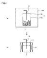
- Fig. 4 is a schematic diagram of a step showing a method of introducing an alkali-metal-element-containing substance into an alkali-metal-element-containing substance supply container in the present invention; (a) shows the step of introducing the alkali-metal-element-containing substance into the alkali-metal-element-containing substance supply container; and (b) shows the step of melting the alkali-metal-element-containing substance.
- Fig. 5 is a schematic diagram of a method of controlling moisture concentration in a drying container used in the present invention.
- Fig. 6 is a schematic cross-sectional view of a semiconductor device according to the present invention.
- 1 alkali-metal-element-containing substance; 2 group III-element-containing substance; 3 nitrogen-element-containing substance; 4 group III-alkali melt; 5 melt; 6 group III-nitride crystal; 11 alkali-metal-element-containing substance introduction valve; 12 alkali-metal-element-containing substance supply line; 13 alkali-metal-element-containing substance supply valve; 14 alkali metal element supply container; 14a alkali metal element supply container main body; 14b alkali metal element supply container cover; 15, 53, 53a, 53b heater; 21 group III-element-containing substance introduction valve; 22 group III-element-containing substance supply line; 23 group III-element-containing substance supply valve; 24 group III-element-containing substance supply container; 31 nitrogen-element-containing substance introduction valve; 32 nitrogen-element-containing substance supply line; 33 nitrogen-element-containing substance supply valve; 34 nitrogen-element-containing substance supply container; 41, 42, 43 evacuation valve; 44 evacuation apparatus; 51 reactor; 51 a reactor main body; 51b reactor cover; 52 crystal growth container; 60 GaN crystal substrate; 61 n-type GaN layer; 62 multiple quantum well structure; 63 p-type In0.20Ga0.80N layer; 64 p-type GaN layer; 65 p-side electrode; 66 n-side electrode; 80 light emission; 100 drying container; 100a main container; 100b side container; 101 main purge valve; 102 moisture meter; 103 oximeter; 104 side purge valve; 105 armhole; 106 glove; 111 blower; 112 cooling tower; 113 cooler; 114 dehydration/deoxidation tower; 115 circulation valve; 121 inert gas supply container; 122 inert gas supply source valve; 123 inert gas main supply valve; 124 inert gas side supply valve; 131 vacuum pump; 132 leakage electromagnetic valve; 133 main evacuation valve; 134 side evacuation valve; and 141 baby compressor.
- Referring to Fig. 1, a method of manufacturing a group III-nitride crystal substrate according to the present invention is directed to a method of manufacturing a group III-nitride crystal substrate in which group III-
nitride crystal 6 grows from amelt 5 containing an alkali metal element, a group III-element and a nitrogen element. The method includes the steps of: introducing an alkali-metal-element-containingsubstance 1 containing the alkali metal element, a group III-element-containingsubstance 2 containing the group III-element, and a nitrogen-element-containingsubstance 3 containing the nitrogen element into areactor 51 as shown in Fig. 1(a); formingmelt 5 containing at least the alkali metal element, the group III-element and the nitrogen element inreactor 51 as shown in Fig. 1(b); and growing group III-nitride crystal 6 frommelt 5 as shown in Fig. 1(c). At least in the step of introducing alkali-metal-element-containingsubstance 1 intoreactor 51, alkali-metal-element-containingsubstance 1 is handled in adrying container 100 in which a moisture concentration is controlled to at most 1.0ppm (dew point: -76°C). By setting the moisture concentration within dryingcontainer 100 to at most 1.0ppm (dew point: -76°C), oxidation of the alkali-metal-element-containing substance is prevented and introduction of an oxygen atom into the group III-nitride crystal can be suppressed, whereby a group III-nitride crystal substrate attaining a small absorption coefficient can be obtained. From such a viewpoint, it is preferable to set the moisture concentration within dryingcontainer 100 to at most 0.54ppm (dew point: -80°C). - In order to prevent oxidation of the alkali-metal-element-containing substance,
drying container 100 is filled with an inert gas such as an Ar gas or N2 gas. Preferably, the oxygen concentration within the drying container is set to at most 5ppm. Handling of the alkali-metal-element-containing substance specifically refers to taking out a prescribed amount of the alkali-metal-element-containing substance from a storage container, followed by introduction of the same into the reactor. - The alkali-metal-element-containing substance, the group III-element-containing substance and the nitrogen-element-containing substance may be in any form of gas, liquid and solid, and how and when they are introduced into the reactor may be different among one another. An example of the alkali-metal-element-containing substance includes an alkali metal such as metal Na, an alkali metal element compound such as NaN3, and the like. An example of the group III-element-containing substance includes a group III-element metal such as metal Ga, metal AI and metal In, a group III-element compound such as GaN and GaAs, and the like. An example of the nitrogen-element-containing substance includes not only N2 gas but also a nitrogen compound such as NH3 gas, NaN3 and the like.
- Referring to Fig. 1, the present embodiment will further specifically be described. Initially, as shown in Fig. 1(a), in the step of introducing alkali-metal-element-containing
substance 1, group III-element-containingsubstance 2 and nitrogen-element-containingsubstance 3 intoreactor 51,reactor 51 is accommodated indrying container 100 in which a moisture concentration is controlled to at most 1.0ppm (dew point: -76°C) and preferably to at most 0.54ppm (dew point: -80°C). Thereafter, areactor cover 51b is detached from a reactormain body 51a, and a prescribed amount of each of alkali-metal-element-containingsubstance 1 such as metal Na, group III-element-containingsubstance 2 such as metal Ga, and nitrogen-element-containingsubstance 3 such as NaN3 or GaN is accommodated in acrystal growth container 52 provided within reactormain body 51a. Reactormain body 51a is sealed byreactor cover 51b, and taken out of the drying container. As alkali-metal-element-containingsubstance 1 is handled within dryingcontainer 100 in which the moisture concentration is controlled to at most 1.0ppm (dew point: -76°C), it is not oxidized. - As shown in Fig. 1(b), in the step of forming
melt 5 containing at least the alkali metal element, the group III-element and the nitrogen element inreactor 51, a nitrogen-element-containingsubstance introduction valve 31 ofreactor 51 is connected to a nitrogen-element-containingsubstance supply line 32, and aheater 53 is disposed aroundreactor 51. An inert gas withinreactor 51 is removed through anevacuation valve 43 by means of anevacuation apparatus 44 such as a vacuum pump, and thereafter, nitrogen-element-containingsubstance introduction valve 31 is opened to introduce N2 gas intoreactor 51. Then,reactor 51 is heated byheater 53. In this manner, the alkali-metal-element-containing substance, the group III-element-containing substance and the nitrogen-containing substance are melted to formmelt 5 containing the alkali metal element (such as Na), the group III-element (such as Ga) and the nitrogen element (N). As the alkali-metal-containing substance is not oxidized, the oxygen concentration inmelt 5 is low. - As shown in Fig. 1(c), a prescribed pressure and temperature of
reactor 51 are set by controlling thermal output ofheater 53, so as to grow GaN crystal representing group III-nitride crystal 6 frommelt 5. As the oxygen concentration inmelt 5 is low, the oxygen concentration of obtained group III-nitride crystal 6 is also low. - In growing group III-
nitride crystal 6 frommelt 5, from the viewpoint of promoted growth of group III-nitride crystal 6, the temperature of group III-nitride crystal 6 is preferably lower than the temperature ofmelt 5 or the nitrogen-containing substance that remains without being dissolved in the melt. For example, by controlling thermal output of aheater 53a and thermal output of aheater 53b, the temperature of the nitrogen-containing substance ormelt 5 can be set higher than the temperature of group III-nitride crystal 6. In addition, though not shown, from the viewpoint of promoted growth of the group III-nitride crystal, preferably, seed crystal is introduced in advance into the reactor along with the alkali-metal-element-containing substance, the group III-element-containing substance and the nitrogen-element-containing substance such that the seed crystal is present in the melt while the group III-nitride crystal grows. Though the seed crystal is not particularly limited, group III-nitride crystal of the same type as the group III-nitride crystal that desirably grows is preferable. - The group III-nitride crystal that has grown is taken out of
reactor 51 and cut to a prescribed size, and has its surface polished. The group III-nitride crystal substrate attaining low oxygen concentration and small absorption coefficient is thus obtained. - According to the present embodiment, the step of introducing the alkali-metal-element-containing substance, the group III-element-containing substance and the nitrogen-element-containing substance into the reactor is implemented by the steps of introducing the alkali-metal-element-containing substance and the group III-element-containing substance into the reactor, forming the group III-alkali melt containing at least the alkali metal element and the group III-element in the reactor, and introducing the nitrogen-containing substance into the group III-alkali melt, and the step of forming the melt containing at least the alkali metal element, the group III-element and the nitrogen element in the reactor is implemented by the step of dissolving the nitrogen-element-containing substance in the group III-alkali melt.
- Referring to Fig. 2, the present embodiment will specifically be described. Initially, the step of introducing alkali-metal-element-containing
substance 1, group III-element-containingsubstance 2 and nitrogen-element-containingsubstance 3 intoreactor 51 will be described. First, as shown in Fig. 2(a),reactor 51 having at least nitrogen-element-containingsubstance introduction valve 31 is accommodated in dryingcontainer 100 in which a moisture concentration is controlled to at most 1.0ppm (dew point: -76°C) and preferably to at most 0.54ppm (dew point: 80°C). Thereafter,reactor cover 51b is detached from reactormain body 51a, and a prescribed amount of each of alkali-metal-element-containingsubstance 1 such as metal Na and group III-element-containingsubstance 2 such as metal Ga is accommodated incrystal growth container 52 provided within reactormain body 51a. Reactormain body 51a is sealed byreactor cover 51b, and taken out of the drying container. As alkali-metal-element-containingsubstance 1 is handled within dryingcontainer 100 in which the moisture concentration is controlled to at most 1.0ppm (dew point: -76°C), it is not oxidized. - As shown in Fig. 2(b), nitrogen-element-containing
substance introduction valve 31 ofreactor 51 is connected to nitrogen-element-containingsubstance supply line 32, andheater 53 is disposed aroundreactor 51. An inert gas withinreactor 51 is removed throughevacuation valve 43 by means ofevacuation apparatus 44 such as a vacuum pump, and thereafter, a nitrogen-element-containingsubstance supply container 34 is used to introduce N2 gas intoreactor 51 through nitrogen-element-containingsubstance introduction valve 31. Then,reactor 51 is heated byheater 53, so as to melt alkali-metal-element-containingsubstance 1 and group III-element-containingsubstance 2, thereby forming group III-alkali melt 4 containing the alkali metal element (such as Na) and the group III-element (such as Ga). As the alkali-metal-containing substance is prevented from oxidation, the oxygen concentration in group III-alkali melt 4 is low. Then, nitrogen-element-containingsubstance supply container 34 is used to introduce again nitrogen-element-containingsubstance 3 such as N2 gas intoreactor 51 through nitrogen-element-containingsubstance introduction valve 31, so as to adjust the pressure withinreactor 51. - As shown in Figs. 2(b) and 2(c), N2 gas representing nitrogen-element-containing
substance 3 that has been introduced intoreactor 51 is dissolved in group III-alkali melt 4, to formmelt 5 containing the alkali metal element (such as Na), the group III-element (such as Ga) and the nitrogen element (N). As the oxygen concentration in group III-alkali melt 4 is low, the oxygen concentration inmelt 5 is also low. - As shown in Fig. 2(d), a prescribed pressure and temperature of
reactor 51 are set by controlling thermal output ofheater 53 and by regulating nitrogen-element-containingsubstance introduction valve 31, nitrogen-element-containingsubstance supply valve 33 andevacuation valve 43, so as to grow GaN crystal representing group III-nitride crystal 6 frommelt 5. As the oxygen concentration inmelt 5 is low, the oxygen concentration of obtained group III-nitride crystal 6 is also low. - In growing group III-
nitride crystal 6 frommelt 5, from the viewpoint of promoted growth of group III-nitride crystal 6, such temperature gradient that a liquid temperature decreases from the surface ofmelt 5 toward the surface of group III-nitride crystal 6 is preferably set. In addition, though not shown, from the viewpoint of promoted growth of the group III-nitride crystal, preferably, seed crystal is introduced in advance into the reactor along with the alkali-metal-element-containing substance and the group III-element-containing substance such that the seed crystal is present in the melt while the group III-nitride crystal grows. Though the seed crystal is not particularly limited, group III-nitride crystal of the same type as the group III-nitride crystal that desirably grows is preferable. - The group III-nitride crystal that has grown is taken out of
reactor 51 and cut to a prescribed size, and has its surface polished. The group III-nitride crystal substrate attaining low oxygen concentration and small absorption coefficient is thus obtained. - According to the present embodiment, though it is not necessary to handle the alkali-metal-element-containing substance in the drying container in which a moisture concentration is controlled to at most 1.0ppm (dew point: -76°C) and preferably to at most 0.54ppm (dew point: -80°C) in the step of introducing the alkali-metal-element-containing substance into the reactor in
Embodiment 1 orEmbodiment 2, a growth temperature of the group III-nitride crystal is set to at least 850°C at least in the step of growing group III-nitride crystal 6 (such as GaN crystal) frommelt 5 containing the alkali metal element (such as Na), the group III-element (such as Ga) and the nitrogen element (N). - That is, in Fig. 1(c) or Fig. 2(d), the crystal growth temperature in growing group III-
nitride crystal 6 from melt 5 (the temperature of a growing portion of group III-nitride crystal 6, that is, the temperature corresponding to that at an interface betweenmelt 5 and group III-nitride crystal 6 that grows) is set to at least 850°C. - As the growth temperature of the group III-nitride crystal is higher, a rate of oxygen atom taken into the crystal becomes lower and the concentration of oxygen contained in the group III-nitride crystal (such as GaN crystal) becomes lower. This may be because, as the growth temperature of the crystal is higher, each atom tends to be arranged in a more thermodynamically stable state and taking-in of the oxygen atom different in atomic radius from a group III-element atom and a nitrogen atom becomes less likely. Accordingly, the growth temperature of the group III-nitride crystal is set preferably to at least 880°C and more preferably to at least 910°C. Therefore, the group III-nitride crystal substrate obtained by cutting and polishing the group III-nitride crystal attains low oxygen concentration and small absorption coefficient.
- According to the present embodiment, in the step of growing group III-nitride crystal 6 (such as GaN crystal) from
melt 5 containing the alkali metal element (such as Na), the group III-element (such as Ga) and the nitrogen element (N) inEmbodiment 1 orEmbodiment 2, a growth temperature of the group III-nitride crystal is set to at least 850°C. - Referring to Figs. 1 and 2, at least in the step of introducing alkali-metal-element-containing
substance 1 intoreactor 51 as shown in Fig. 1(a) or Fig. 2(a), alkali-metal-element-containingsubstance 1 is handled in dryingcontainer 100 in which a moisture concentration is controlled to at most 1.0ppm (dew point: -76°C) and preferably to at most 0.54ppm (dew point: -80°C), and in the step of growing group III-nitride crystal 6 frommelt 5 as shown in Fig. 1(c) or Fig. 2(d), the growth temperature of group III-nitride crystal 6 is set to at least 850°C. In the present embodiment, introduction of oxygen atom into the melt and hence introduction of oxygen atom into the group III-nitride crystal is suppressed, so that the oxygen concentration in the group III-nitride crystal substrate can further be lowered. - According to the present embodiment, at least the step of growing the group III-nitride crystal from the melt containing the alkali metal element, the group III-element and the nitrogen element in any one of
Embodiments 1 to 4 includes the step of introducing at least one of the alkali-metal-element-containing substance, the group III-element-containing substance and the nitrogen-element-containing substance into the reactor. - Referring to Fig. 3, application of the present embodiment in
Embodiment 2 will be described. Initially, as shown in Fig. 3(a), a prescribed amount of each of alkali-metal-element-containingsubstance 1 such as metal Na and group III-element-containingsubstance 2 such as metal Ga is accommodated incrystal growth container 52 provided within reactormain body 51a in dryingcontainer 100 in which a moisture concentration is controlled to at most 1.0ppm (dew point: -76°C) and preferably to at most 0.54ppm (dew point: -80°C). Reactormain body 51a is sealed byreactor cover 51b, and taken out of dryingcontainer 100.Reactor 51 employed in the present embodiment is provided with an alkali-metal-element-containingsubstance introduction valve 11, a group III-element-containingsubstance introduction valve 21, and nitrogen-element-containingsubstance introduction valve 31. - As shown in Fig. 3(b), nitrogen-element-containing
substance introduction valve 31 ofreactor 51 is connected to nitrogen-element-containingsubstance supply line 32, group III-element-containingsubstance introduction valve 21 is connected to a group III-element-containingsubstance supply line 22, alkali-metal-element-containingsubstance introduction valve 11 is connected to an alkali-metal-element-containingsubstance supply line 12, andheater 53 is disposed aroundreactor 51. An inert gas withinreactor 51 is removed throughevacuation valve 43 by means ofevacuation apparatus 44 such as a vacuum pump, and thereafter, nitrogen-element-containingsubstance supply container 34 is used to introduce N2 gas intoreactor 51 through nitrogen-element-containingsubstance introduction valve 31. Then,reactor 51 is heated byheater 53 so as to melt alkali-metal-element-containing substance 1 (such as Na) and group III-element-containing substance 2 (such as Ga), thereby forming group III-alkali melt 4 (such as a Ga-Na melt) containing the alkali metal element (such as Na) and the group III-element (such as Ga). Then, nitrogen-element-containingsubstance supply container 34 is used to introduce nitrogen-element-containingsubstance 3 such as N2 gas intoreactor 51 through nitrogen-element-containingsubstance introduction valve 31. - As shown in Figs. 3(b) and 3(c), N2 gas representing nitrogen-element-containing
substance 3 that has been introduced intoreactor 51 is dissolved in group III-alkali melt 4, so as to formmelt 5 containing the alkali metal element (such as Na), the group III-element (such as Ga) and the nitrogen element (N). - As shown in Fig. 3(d), a prescribed pressure and temperature of
reactor 51 are set by controlling thermal output ofheater 53 and by regulating nitrogen-element-containingsubstance introduction valve 31, nitrogen-element-containingsubstance supply valve 33 andevacuation valve 43, so as to grow GaN crystal representing group III-nitride crystal 6 frommelt 5. Here, as the composition of the alkali metal element, the group III-element and the nitrogen element inmelt 5 changes with growth of group III-nitride crystal 6, crystal growth is inhibited. - In contrast, as shown in Fig. 3(d), N2 gas representing nitrogen-element-containing
substance 3 is introduced intoreactor 51 from nitrogen-element-containingsubstance supply container 34 through nitrogenelement supply valve 33, nitrogen-element-containingsubstance supply line 32 and nitrogen-element-containingsubstance introduction valve 31. In addition, after an atmosphere remaining in group III-element-containingsubstance supply line 22 is removed by means ofevacuation apparatus 44 through anevacuation valve 42, liquid metal Ga representing group III-element-containingsubstance 2 is introduced intocrystal growth container 52 withinreactor 51 from a group III-element-containingsubstance supply container 24 through group III-element-containingsubstance supply valve 23, group III-element-containingsubstance supply line 22 and group III-element-containingsubstance introduction valve 21. Moreover, after an atmosphere remaining in alkali-metal-element-containingsubstance supply line 12 is removed by means ofevacuation apparatus 44 through anevacuation valve 41, liquid metal Na representing alkali-metal-element-containingsubstance 1 is introduced intocrystal growth container 52 withinreactor 51 from an alkali-metal-element-containingsubstance supply container 14 through alkali-metal-element-containingsubstance supply valve 13, alkali-metal-element-containingsubstance supply line 12 and alkali-metal-element-containingsubstance introduction valve 11. - As described above, in the step of growing the group III-nitride crystal, at least one of the alkali-metal-element-containing substance, the group III-element-containing substance and the nitrogen-element-containing substance is introduced into the reactor as appropriate or continuously, so that the group III-nitride crystal can grow for a long time with a composition ratio of the alkali-metal-element-containing substance, the group III-element-containing substance and the nitrogen-element-containing substance being maintained constant. Therefore, the group III-nitride crystal substrate attaining low oxygen concentration, a small absorption coefficient, and a large size can be obtained.
- When the alkali metal element is accommodated in the alkali-metal-element-containing substance supply container as well, from the viewpoint of prevention of oxidation of the alkali-metal-element-containing substance, the alkali-metal-element-containing substance is preferably handled in the drying container in which a moisture concentration is controlled to at most 1.0ppm (dew point: -76°C) and preferably to at most 0.54ppm (dew point: -80°C). For example, referring to Fig. 4, as shown in Fig. 4(a), metal Na representing alkali-metal-element-containing
substance 1 is accommodated in an alkali-metal-element-containing substance supply containermain body 14a in dryingcontainer 100. Then, alkali-metal-element-containing substance supply containermain body 14a is sealed by an alkali-metal-element-containing substancesupply container cover 14b and taken out of dryingcontainer 100. Thereafter, alkali-metal-element-containingsubstance supply container 14 is heated by a heater, so as to obtain liquid metal Na serving as alkali-metal-element-containingsubstance 1. - Referring to Fig. 5, a method of controlling a moisture concentration (or a method of controlling a dew point) in drying
container 100 used inEmbodiments 1 to 5 above will now be described. Dryingcontainer 100 is formed by amain container 100a and aside container 100b.Gloves 106 are provided inarmholes 105 ofmain container 100a, so that an operation withinmain container 100a of dryingcontainer 100 can be performed by inserting hands ingloves 106. - Referring to Fig. 5, in
main container 100a orside container 100b, avacuum pump 131, amain evacuation valve 133 and a side evacuation valve 143 for evacuatingmain container 100a and/orside container 100b are disposed, and an inertgas supply container 121, an inert gassupply source valve 122, an inert gasmain supply valve 123, and an inert gasside supply valve 124 for supplying an inert gas tomain container 100a and/orside container 100b are disposed. In addition, ablower 111, acooling tower 112, a cooler 113, a dehydration/deoxidation tower 114, acirculation valve 115, amoisture meter 102, and anoximeter 103 for attaining, maintaining and controlling the moisture concentration to at most 1.0ppm (dew point: -76°C) and preferably to at most 0.54ppm (dew point: -80°C) are provided inmain container 100a. Here,cooling tower 112 is cooled by cooler 113, and dehydration/deoxidation tower 114 is filled with a dehydrator such as molecular sieve and a deoxidizer such as reduced copper. - In order to lower the moisture concentration in
main container 100a and inside container 100b of dryingcontainer 100,main container 100a andside container 100b are evacuated by means ofvacuum pump 131. Thereafter, Ar gas or N2 gas serving as the inert gas is introduced from inertgas supply container 121. In addition, in order to control the moisture concentration inmain container 100a of dryingcontainer 100 to at most 1.0ppm (dew point: -76°C) and preferably to at most 0.54ppm (dew point: -80°C), the inert gas that fillsmain container 100a is circulated sequentially fromblower 111 then tocooling tower 112, dehydration/deoxidation tower 114 and tomain container 100a, while measuring the moisture concentration and the oxygen concentration withinmain container 102 usingmoisture meter 102 andoximeter 103 provided inmain container 100a. The inert gas circulated as described above serves for dehydration and deoxidation when it passes through dehydration/deoxidation tower 114. Therefore, by regulating an amount of circulated inert gas and by setting a cooling temperature in the cooling tower to at most 0°C, the moisture concentration inmain container 100a can be controlled to at most 1.0ppm and preferably to at most 0.54ppm also during an operation which will be described below. - In handling the alkali-metal-element-containing substance or the like in drying
container 100, for example, the reactor and a container for storage of the alkali-metal-element-containing substance are first placed inside container 100b.Side container 100b is then evacuated and thereafter filled with an inert gas such as Ar gas or N2 gas. Then, a partition between the side container and the main container is removed, so that the reactor and the container for storage of the alkali-metal-element-containing substance are moved from the side container to the main container. The reactor and the container for storage of the alkali-metal-element-containing substance are opened in the main container in which the moisture concentration is controlled, the alkali-metal-element-containing substance or the like is accommodated in the reactor, and the reactor is sealed. After the sealed reactor is moved to the side container, it is taken out of dryingcontainer 100. As a result of such handling, the alkali-metal-element-containing substance can be introduced into the reactor without being oxidized, while the moisture concentration in the main container is controlled to at most 1.0ppm (dew point: -76°C) and preferably to at most 0.54ppm (dew point: -80°C). - The present embodiment is directed to a group III-nitride semiconductor device having at least one group III-nitride layer formed on the group III-nitride crystal substrate obtained in
Embodiments 1 to 5. Referring to Fig. 6, the semiconductor device according to the present embodiment implements an LED, in which an n-type GaN layer 61, a multiplequantum well structure 62 implemented by stacking one or more pair of an In0.15Ga0.85N layer and a GaN layer, a p-type Al0.20Ga0.80N layer 63, and a p-type GaN layer 64 as the group III-nitride crystal layer are successively formed on aGaN substrate 60 serving as the group III-nitride crystal substrate with MOCVD (Metal Organic Chemical Vapor Deposition), an n-side electrode 66 is formed under the GaN substrate, and a p-side electrode 65 is formed on p-type GaN layer 64. As the LED in the present embodiment employs the group III-nitride substrate that attains low oxygen concentration and small absorption coefficient, its light emission intensity is high. - From the viewpoint of improvement in light emission intensity of the LED, the group III-nitride crystal substrate according to the present invention obtained in
Embodiments 1 to 5 preferably attains an absorption coefficient, in a wavelength range from 400nm to 600nm, of at most 40cm-1 and preferably of at most 20cm-1. In addition, from the viewpoint of improvement in light emission intensity of the LED, the group III-nitride crystal substrate according to the present invention attains an oxygen concentration of at most 1×10¹⁷/cm3, preferably of at most 5×10¹⁶/cm3, and more preferably of at most 2×10¹⁶/cm3. - The present example corresponds to
Embodiment 2 above. Referring to Fig. 2, as shown in Fig. 2(a), in dryingcontainer 100 in which a moisture concentration was controlled to 0.09ppm to 0.54ppm (dew point: -90°C to -80°C) and the oxygen concentration was controlled to 0.3ppm to 0.8ppm, 10g of metal Na (purity 99.95%) representing alkali-metal-element-containingsubstance 1 and 10g of metal Ga (purity 99.9999%) representing group III-element-containingsubstance 2 were accommodated, along with 170mg GaN seed crystal serving as the seed crystal, in crystal growth container (crucible) 52 (a mol percent in composition of metal Ga and metal Na was set to 25% and 75%, respectively). Here,crystal growth container 52 having a diameter of 1.9cm and a height of 8cm and made of Al2O3 (purity 99.99%) was provided inreactor 51 having a diameter of 2.5cm and a height of 10cm and made of SUS. - As shown in Fig. 2(b), nitrogen-element-containing
substance introduction valve 31 ofreactor 51 was connected to nitrogen-element-containingsubstance supply line 32, andheater 53 was disposed aroundreactor 51. N2 gas (purity 99.9999%) representing nitrogen-element-containingsubstance 3 was introduced intoreactor 51 from nitrogen-element-containingsubstance supply container 34 through nitrogen-element-containingsubstance supply valve 33 and nitrogen-element-containingsubstance introduction valve 31. Then,reactor 51 was heated byheater 53, so as to form a Ga-Na melt representing group III-alkali melt 4 (the liquid temperature at the surface of the melt was set to 780°C). Here, nitrogen-element-containingsubstance supply valve 33 and nitrogen-element-containingsubstance introduction valve 31 were regulated such that a gas partial pressure of N2 gas attained to 50 atmospheric pressure (5.065MPa). - As shown in Fig. 2(c), N2 gas was dissolved in the Ga-Na melt, to form
melt 5 containing the alkali metal element (Na), the group III-element (Ga) and the nitrogen element (N) (the liquid temperature at the surface of the melt was set to 780°C). As shown in Fig. 2(d), GaN crystal representing group III-nitride crystal 6 was grown frommelt 5. Here,heaters melt 5 and group III-nitride crystal 6) was set to 750°C. - The GaN crystal was taken out from
reactor 51, followed by cutting and surface polishing. Then, the GaN crystal substrate having a size of 10mm×10mm×300µm thickness was obtained. The GaN crystal substrate attained the maximum absorption coefficient, in a wavelength range from 400nm to 600nm, of 30cm-1, and attained the oxygen concentration of 5×10¹⁶/cm3. The absorption coefficient was measured using a spectrophotometer, while the oxygen concentration was measured by SIMS (Secondary Ion Mass Spectroscopy). - Referring to Fig. 6, an LED device was obtained by successively forming n-
type GaN layer 61 having a thickness of 2µm, multiplequantum well structure 62 implemented by stacking three pairs of the In0.15Ga0.85N layer having a thickness of 3nm and the GaN layer having a thickness of 15nm, p-type Al0.20Ga0.80N layer 63 having a thickness of 20nm, and p-type GaN layer 64 having a thickness of 100nm on a (0001) surface (upper surface) ofGaN crystal substrate 60 with MOCVD, by forming n-side electrode 66 having a diameter of 50µm in the center of a lower surface of the GaN substrate, and by forming p-side electrode 65 on the upper surface of p-type GaN layer 64. Here, Si was selected as an n-type dopant, while Mg was selected as a p-type dopant. Relative light emission intensity when a current of 20mA was fed to these electrodes of the LED device attained to 3.7, as compared with 1.0 attained by the LED device according to Comparative Example 1 which will be described later. Light emission intensity of the LED device was measured using a spectrophotometer. The result is summarized in Table 1. - The present example corresponds to
Embodiment 2 above. Referring to Fig. 2(a), the GaN crystal substrate was obtained as in Example 1, except that the step of introducing alkali-metal-element-containing substance 1 (metal Na) and group III-element-containing substance 2 (metal Ga) intocrystal growth container 52 provided inreactor 51 was performed in dryingcontainer 100 in which the moisture concentration was controlled to 0.54ppm to 1.0ppm (dew point: -80°C to -76°C) and the oxygen concentration was controlled to 0.3ppm to 0.5ppm. The obtained GaN crystal substrate attained the maximum absorption coefficient, in a wavelength range from 400nm to 600nm, of 40cm-1, and attained the oxygen concentration of 8×10¹⁶/cm3. In addition, the GaN crystal substrate was used to fabricate the LED device, as in Example 1. The obtained LED device attained the relative light emission intensity of 2.1. The result is summarized in Table 1. - The present example corresponds to
Embodiment 3 above. The GaN crystal substrate was obtained as in Example 1, except that the step of introducing alkali-metal-element-containing substance 1 (metal Na) and group III-element-containing substance 2 (metal Ga) intocrystal growth container 52 provided inreactor 51 was performed in dryingcontainer 100 in which the moisture concentration was controlled to 1.0ppm to 2.6ppm (dew point: -76°C to -70°C) and the oxygen concentration was controlled to 0.3ppm to 0.5ppm as shown in Fig. 2(a), and except that the liquid temperature at the surface of the melt was set to 880°C and the growth temperature of the GaN crystal was set to 850°C in the step of growing group III-nitride crystal 6 (GaN crystal) frommelt 5 as shown in Fig. 2(d). The obtained GaN crystal substrate attained the maximum absorption coefficient, in a wavelength range from 400nm to 600nm, of 30cm-1, and attained the oxygen concentration of 5×10¹⁶/cm3. In addition, the GaN crystal substrate was used to fabricate the LED device, as in Example 1. The obtained LED device attained the relative light emission intensity of 3.7. The result is summarized in Table 1. - The present example also corresponds to
Embodiment 3. The GaN crystal substrate was obtained as in Example 3, except that the liquid temperature at the surface of the melt was set to 910°C and the growth temperature of the GaN crystal was set to 880°C in the step of growing group III-nitride crystal 6 (GaN crystal) frommelt 5 as shown in Fig. 2(d). The obtained GaN crystal substrate attained the maximum absorption coefficient, in a wavelength range from 400nm to 600nm, of 30cm-1, and attained the oxygen concentration of 5×10¹⁶/cm3. In addition, the GaN crystal substrate was used to fabricate the LED device, as in Example 1. The obtained LED device attained the relative light emission intensity of 3.7. The result is summarized in Table 1. - The present example corresponds to
Embodiment 4. The GaN crystal substrate was obtained as in Example 1, except that the liquid temperature at the surface of the melt was set to 880°C and the growth temperature of the GaN crystal was set to 850°C in the step of growing group III-nitride crystal 6 (GaN crystal) frommelt 5 as shown in Fig. 2(d). The obtained GaN crystal substrate attained the maximum absorption coefficient, in a wavelength range from 400nm to 600nm of 20cm-1, and attained the oxygen concentration of 2×10¹⁶/cm3. In addition, the GaN crystal substrate was used to fabricate the LED device, as in Example 1. The obtained LED device attained the relative light emission intensity of 8.5. The result is summarized in Table 1. - The present example also corresponds to
Embodiment 4. The GaN crystal substrate was obtained as in Example 1, except that the liquid temperature at the surface of the melt was set to 910°C and the growth temperature of the GaN crystal was set to 880°C in the step of growing group III-nitride crystal 6 (GaN crystal) frommelt 5 as shown in Fig. 2(d). The obtained GaN crystal substrate attained the maximum absorption coefficient, in a wavelength range from 400nm to 600nm, of 18cm-1, and attained the oxygen concentration of 2× 10¹⁶/cm3. In addition, the GaN crystal substrate was used to fabricate the LED device, as in Example 1. The obtained LED device attained the relative light emission intensity of 8.9. The result is summarized in Table 1. - The present example also corresponds to
Embodiment 4. The GaN crystal substrate was obtained as in Example 1, except that the liquid temperature at the surface of the melt was set to 910°C and the growth temperature of the GaN crystal was set to 910°C in the step of growing group III-nitride crystal 6 (GaN crystal) frommelt 5 as shown in Fig. 2(d). The obtained GaN crystal substrate attained the maximum absorption coefficient, in a wavelength range from 400nm to 600nm, of 12cm-1, and attained the oxygen concentration of 1×10¹⁶/cm3. In addition, the GaN crystal substrate was used to fabricate the LED device, as in Example 1. The obtained LED device attained the relative light emission intensity of 15. The result is summarized in Table 1. - The GaN crystal substrate was obtained as in Example 3, except that the liquid temperature at the surface of the melt was set to 840°C and the growth temperature of the GaN crystal was set to 810°C in the step of growing group III-nitride crystal 6 (GaN crystal) from
melt 5 as shown in Fig. 2(d). The obtained GaN crystal substrate attained the maximum absorption coefficient, in a wavelength range from 400nm to 600nm, of 120cm-1, and attained the oxygen concentration of 1.5×10¹⁷/cm3. In addition, the GaN crystal substrate was used to fabricate the LED device, as in Example 1. As described above, the LED device obtained in this comparative example attained the relative light emission intensity of 1.0. The result is summarized in Table 1. - The present example also corresponds to
Embodiment 4. According to the Examples 1 to 7 and Comparative Example 1 described above, alkali-metal-element-containing substance 1 (metal Na) and group III-element-containing substance 2 (metal Ga) were introduced intoreactor 51 to obtain group III-alkali melt 4, and thereafter the nitrogen-element-containing substance (N2 gas) was dissolved in group III-alkali melt 4 to formmelt 5, as shown in Fig. 2. On the other hand, the present embodiment is different from the former in that metal Na representing alkali-metal-element-containingsubstance 1 and NaN3 representing group III-element-containingsubstance 2 and nitrogen-element-containingsubstance 3 were introduced intoreactor 51 and melted to formmelt 5, as shown in Fig. 1. - Namely, according to the present example, referring to Fig. 1, as shown in Fig. 1(a), in drying
container 100 in which the moisture concentration was controlled to 0.09ppm to 0.54ppm (dew point: -90°C to -80°C) and the oxygen concentration was controlled to 0.4ppm to 0.9ppm, 28.3g of NaN3 representing alkali-metal-element-containingsubstance 1 and nitrogen-element-containingsubstance 3 and 10g of metal Ga representing group III-element-containingsubstance 2 were accommodated, along with 170mg of GaN seed crystal serving as the seed crystal, in crystal growth container (crucible) 52 (a mol percent in composition of metal Ga and metal Na was set to 25% and 75%, respectively). Here,crystal growth container 52 having a diameter of 1.9cm and a height of 20cm and made of Al2O3 was provided inreactor 51 having a diameter of 2.5cm and a height of 21cm and made of SUS. - As shown in Fig. 1(b), nitrogen-element-containing
substance introduction valve 31 ofreactor 51 was connected to nitrogen-element-containingsubstance supply line 32, andheater 53 was disposed aroundreactor 51. Then,reactor 51 was heated byheater 53 so as to formmelt 5 containing the alkali metal element (Na), the group III-element (Ga) and the nitrogen element (N) (the liquid temperature at the surface of the melt was set to 880°C). Here, the pressure inreactor 51 was controlled to 50 atmospheric pressure (5.065MPa) by partially discharging N2 gas, that was produced as a result of decomposition of NaN3, toevacuation apparatus 44 throughevacuation valve 43. - As shown in Fig. 1(c), GaN crystal representing group III-
nitride crystal 6 was grown frommelt 5. Here,heaters melt 5 and group III-nitride crystal 6) was set to 850°C. - The GaN crystal was taken out from
reactor 51, followed by cutting and surface polishing. Then, the GaN crystal substrate having a size of 6mm×8mm×300µm thickness was obtained. The GaN crystal substrate attained the maximum absorption coefficient, in a wavelength range from 400nm to 600nm, of 20cm-1, and attained the oxygen concentration of 2× 10¹⁶/cm3. - In addition, the GaN crystal substrate was used to fabricate the LED device, as in Example 1. The obtained LED device attained the relative light emission intensity of 8.5. The result is summarized in Table 1.
Table 1 Example 1 Example 2 Example 3 Example 4 Example 5 Example 6 Example 7 Example 8 Comparative Example 1 Group III-nitride crystal substrate Condition for manufacturing Group III-element-containing substance (g) Ga (10) Ga (10) Ga (10) Ga (10) Ga (10) Ga (10) Ga (10) Ga (10) Ga (10) Alkali-metal-element-containing substance (g) Na (10) Na (10) Na (10) Na (10) Na (10) Na (10) Na (10) NaN3 (28.3) Na (10) Nitrogen-element-containing substance (gas partial pressure MPa) or (g) N2 (5.065) N2 (5.065) N2 (5.065) N2 (5.065) N2 (5.065) N2 (5.065) N2 (5.065) N2 (5.065) Moisture concentration in drying container (ppm) 0.09 to 0.54 0.54 to 1.0 1.0 to 2.6 1.0 to 2.6 0.09 to 0.54 0.09 to 0.54 0.09 to 0.54 0.09 to 0.54 1.0 to 2.6 Dew point in drying container (°C) -90 to -80 -80 to -76 -76 to -70 -76 to -70 -90 to -80 -90 to -80 -90 to -80 -90 to -80 -76 to -70 Temperature at the surface of melt (°C) 780 780 880 910 880 910 910 880 840 Growth temperature of group III-nitride crystal (°C) 750 750 850 880 850 880 910 850 810 Physical property Maximum absorption coefficient in wavelength range from 400nm to 600nm (cm-1) 30 40 30 30 20 18 12 20 120 Oxygen concentration (count/cm3) 5×10¹⁶ 8×10¹⁶ 5×10¹⁶ 5×10¹⁶ 2×10¹⁶ 2×10¹⁶ 1×10¹⁶ 2×10¹⁶ 1.5×10¹⁷ Relative light emission intensity of LED 3.7 2.1 3.7 3.7 8.5 8.9 15 8.5 1.0 - As can clearly be seen from Table 1, the group III-nitride crystal substrate that attains the absorption coefficient, in a wavelength range from 400nm to 600nm, of at most 40cm-1 and attains the oxygen concentration of at most 5×10¹⁶/cm3 was obtained, by handling the alkali-metal-element-containing substance in the drying container in which the moisture concentration was controlled to at most 1.0ppm (dew point: -76°C) and preferably to at most 0.54ppm (dew point: -80°C) in the step of introducing the alkali-metal-element-containing substance in the reactor (Examples 1, 2) or by setting a crystal growth rate to at least 850°C in the step of growing the group III-nitride crystal from the melt containing at least the alkali metal element, the group III-element and the nitrogen element (Examples 3, 4). The relative light emission intensity of the LED device employing the group III-nitride crystal substrate was improved to at least 2.1.
- In addition, the group III-nitride crystal substrate that attains the absorption coefficient, in a wavelength range from 400nm to 600nm, of at most 20cm-1 and attains the oxygen concentration of at most 2× 10¹⁶/cm3 was obtained, by handling the alkali-metal-element-containing substance in the drying container in which the moisture concentration was controlled to at most 0.54ppm (dew point: -80°C) in the step of introducing the alkali-metal-element-containing substance in the reactor and by setting a crystal growth rate to at least 850°C in the step of growing the group III-nitride crystal from the melt containing at least the alkali metal element, the group III-element and the nitrogen element (Example 5 to 8). The relative light emission intensity of the LED device employing the group III-nitride crystal substrate was improved to at least 8.5.
- The embodiments and examples disclosed above are by way of illustration and are not to be taken by way of limitation, the spirit and scope of the present invention being limited not by the embodiments and examples above but by the claims and intended to include all modifications and variations within the scope of the claims.
- As described above, the present invention can widely be utilized in a group III-nitride crystal substrate attaining a small absorption coefficient and a method of manufacturing the same as well as in a group III-nitride semiconductor device.
Claims (21)
- A method of manufacturing a group III-nitride crystal substrate in which group III-nitride crystal (6) grows from a melt (5) containing an alkali metal element, a group III-element and a nitrogen element, comprising the steps of:introducing an alkali-metal-element-containing substance (1) containing said alkali metal element, a group III-element-containing substance (2) containing said group III-element, and a nitrogen-element-containing substance (3) containing said nitrogen element into a reactor (51);forming the melt (5) containing at least said alkali metal element, said group III-element and said nitrogen element in said reactor; andgrowing the group III-nitride crystal (6) from said melt (5); whereinat least in said step of introducing said alkali-metal-element-containing substance (1) into said reactor (51), said alkali-metal-element-containing substance (1) is handled in a drying container (100) in which a moisture concentration is controlled to at most 1.0ppm.
- The method of manufacturing a group III-nitride crystal substrate according to claim 1, wherein
at least in said step of introducing said alkali-metal-element-containing substance (1) into said reactor (51), said alkali-metal-element-containing substance (1) is handled in the drying container (100) in which a moisture concentration is controlled to at most 0.54ppm. - The method of manufacturing a group III-nitride crystal substrate according to claim 1, wherein
said step of introducing said alkali-metal-element-containing substance (1), said group III-element-containing substance (2) and said nitrogen-element-containing substance (3) into said reactor (51) includes the steps of introducing said alkali-metal-element-containing substance (1) and said group III-element-containing substance (2) into said reactor (51), forming a group III-alkali melt (4) containing at least said alkali metal element and said group III-element in said reactor (51), and introducing said nitrogen-containing substance (3) into said group III-alkali melt (4), and
said step of forming the melt (5) containing at least said alkali metal element, said group III-element and said nitrogen element in said reactor (51) includes the step of dissolving the nitrogen-element-containing substance (3) in said group III-alkali melt (4). - The method of manufacturing a group III-nitride crystal substrate according to claim 1, wherein
said step of growing the group III-nitride crystal (6) from said melt (5) further includes the step of introducing at least one of said alkali-metal-element-containing substance (1), said group III-element-containing substance (2) and said nitrogen-element-containing substance (3) into said reactor (51). - A method of manufacturing a group III-nitride crystal substrate in which group III-nitride crystal (6) grows from a melt (5) containing an alkali metal element, a group III-element and a nitrogen element, comprising the steps of:introducing an alkali-metal-element-containing substance (1) containing said alkali metal element, a group III-element-containing substance (2) containing said group III-element, and a nitrogen-element-containing substance (3) containing said nitrogen element into a reactor (51);forming the melt (5) containing at least said alkali metal element, said group III-element and said nitrogen element in said reactor (51); andgrowing the group III-nitride crystal (6) from said melt (5); whereinin said step of growing said group III-nitride crystal (6) from said melt (5), a growth temperature of said group III-nitride crystal (6) is set to at least 850°C.
- The method of manufacturing a group III-nitride crystal substrate according to claim 5, wherein
said step of introducing said alkali-metal-element-containing substance (1), said group III-element-containing substance (2) and said nitrogen-element-containing substance (3) into said reactor (51) includes the steps of introducing said alkali-metal-element-containing substance (1) and said group III-element-containing substance (2) into said reactor (51), forming a group III-alkali melt (4) containing at least said alkali metal element and said group III-element in said reactor (51), and introducing said nitrogen-containing substance (5) into said group III-alkali melt (4), and
said step of forming the melt (5) containing at least said alkali metal element (1), said group III-element (2) and said nitrogen element (3) in said reactor (51) includes the step of dissolving the nitrogen-element-containing substance (3) in said group III-alkali melt (4). - The method of manufacturing a group III-nitride crystal substrate according to claim 5, wherein
said step of growing the group III-nitride crystal (6) from said melt (5) further includes the step of introducing at least one of said alkali-metal-element-containing substance (1), said group III-element-containing substance (2) and said nitrogen-element-containing substance (3) into said reactor (51). - A method of manufacturing a group III-nitride crystal substrate in which group III-nitride crystal (6) grows from a melt (5) containing an alkali metal element, a group III-element and a nitrogen element, comprising the steps of:introducing an alkali-metal-element-containing substance (1) containing said alkali metal element, a group III-element-containing substance (2) containing said group III-element, and a nitrogen-element-containing substance (3) containing said nitrogen element into a reactor (51);forming the melt (5) containing at least said alkali metal element, said group III-element and said nitrogen element in said reactor (51); andgrowing the group III-nitride crystal (6) from said melt (5); whereinat least in said step of introducing said alkali-metal-element-containing substance containing said alkali metal element into said reactor (51), said alkali-metal-element-containing substance (1) is handled in a drying container (100) in which a moisture concentration is controlled to at most 1.0ppm, andin said step of growing said group III-nitride crystal (6) from said melt (5), a growth temperature of said group III-nitride crystal (6) is set to at least 850°C.
- The method of manufacturing a group III-nitride crystal substrate according to claim 8, wherein
at least in said step of introducing said alkali-metal-element-containing substance (1) containing said alkali metal element into said reactor (51), said alkali-metal-element-containing substance (1) is handled in the drying container (100) in which a moisture concentration is controlled to at most 0.54ppm. - The method of manufacturing a group III-nitride crystal substrate according to claim 8, wherein
said step of introducing said alkali-metal-element-containing substance (1), said group III-element-containing substance (2) and said nitrogen-element-containing substance (3) into said reactor (51) includes the steps of introducing said alkali-metal-element-containing substance (1) and said group III-element-containing substance (2) into said reactor (51), forming a group III-alkali melt (4) containing at least said alkali metal element and said group III-element in said reactor (51), and introducing said nitrogen-containing substance (3) into said group III-alkali melt (4), and
said step of forming the melt (5) containing at least said alkali metal element, said group III-element and said nitrogen element in said reactor (51) includes the step of dissolving the nitrogen-element-containing substance (3) in said group III-alkali melt (4). - The method of manufacturing a group III-nitride crystal substrate according to claim 8, wherein
said step of growing the group III-nitride crystal (6) from said melt (5) further includes the step of introducing at least one of said alkali-metal-element-containing substance (1), said group III-element-containing substance (2) and said nitrogen-element-containing substance (3) into said reactor (51). - A group III-nitride crystal substrate manufactured, among methods of manufacturing a group III-nitride crystal substrate in which group III-nitride crystal (6) grows from a melt (5) containing an alkali metal element, a group III-element and a nitrogen element, with a method of manufacturing a group III-nitride crystal substrate comprising the steps of introducing an alkali-metal-element-containing substance (1) containing said alkali metal element, a group III-element-containing substance (2) containing said group III-element, and a nitrogen-element-containing substance (3) containing said nitrogen element into a reactor (51), forming the melt (5) containing at least said alkali metal element, said group III-element and said nitrogen element in said reactor (51), and growing the group III-nitride crystal (6) from said melt (5), and characterized by handling said alkali-metal-element-containing substance (1) in a drying container (100) in which a moisture concentration is controlled to at most 1.0ppm at least in said step of introducing said alkali-metal-element-containing substance (1) into said reactor (51); wherein
said group III-nitride crystal substrate attains an absorption coefficient, in a wavelength range from 400nm to 600nm, of at most 40cm-1. - A group III-nitride semiconductor device, wherein
at least one group III-nitride crystal layer is formed on the group III-nitride crystal substrate according to claim 12. - A group III-nitride crystal substrate manufactured, among methods of manufacturing a group III-nitride crystal substrate in which group III-nitride crystal (6) grows from a melt (5) containing an alkali metal element, a group III-element and a nitrogen element, with a method of manufacturing a group III-nitride crystal substrate comprising the steps of introducing an alkali-metal-element-containing substance (1) containing said alkali metal element, a group III-element-containing substance (2) containing said group III-element, and a nitrogen-element-containing substance (3) containing said nitrogen element into a reactor (51), forming the melt (5) containing at least said alkali metal element, said group III-element and said nitrogen element in said reactor (51), and growing the group III-nitride crystal (6) from said melt (5), and characterized by handling said alkali-metal-element-containing substance (1) in a drying container (100) in which a moisture concentration is controlled to at most 1.0ppm at least in said step of introducing said alkali-metal-element-containing substance into said reactor (51); wherein
the group III-nitride crystal substrate attains an oxygen concentration of at most 1×10¹⁷/cm3. - A group III-nitride semiconductor device, wherein
at least one group III-nitride crystal layer is formed on the group III-nitride crystal substrate according to claim 14. - A group III-nitride crystal substrate manufactured, among methods of manufacturing a group III-nitride crystal substrate in which group III-nitride crystal (6) grows from a melt (5) containing an alkali metal element, a group III-element and a nitrogen element, with a method of manufacturing a group III-nitride crystal substrate comprising the steps of introducing an alkali-metal-element-containing substance (1) containing said alkali metal element, a group III-element-containing substance (2) containing said group III-element, and a nitrogen-element-containing substance (3) containing said nitrogen element into a reactor (51), forming the melt (5) containing at least said alkali metal element, said group III-element and said nitrogen element in said reactor (51), and growing the group III-nitride crystal (6) from said melt (5), and characterized by setting a growth temperature of said group III-nitride crystal (6) to at least 850°C in said step of growing said group III-nitride crystal (6) from said melt (5), wherein
said group III-nitride crystal substrate attains an absorption coefficient, in a wavelength range from 400nm to 600nm, of at most 40cm-1. - A group III-nitride semiconductor device, wherein
at least one group III-nitride crystal layer is formed on the group III-nitride crystal substrate according to claim 16. - A group III-nitride crystal substrate manufactured, among methods of manufacturing a group III-nitride crystal substrate in which group III-nitride crystal (6) grows from a melt (5) containing an alkali metal element, a group III-element and a nitrogen element, with a method of manufacturing a group III-nitride crystal substrate comprising the steps of introducing an alkali-metal-element-containing substance (1) containing said alkali metal element, a group III-element-containing substance (2) containing said group III-element, and a nitrogen-element-containing substance (3) containing said nitrogen element into a reactor (51), forming the melt (5) containing at least said alkali metal element, said group III-element and said nitrogen element in said reactor (51), and growing the group III-nitride crystal (6) from said melt (5), and characterized by setting a growth temperature of said group III-nitride crystal (6) to at least 850°C in said step of growing said group III-nitride crystal (6) from said melt (5), wherein
the group III-nitride crystal substrate attains an oxygen concentration of at most 1×10¹⁷/cm3. - A group III-nitride semiconductor device, wherein
at least one group III-nitride crystal layer is formed on the group III-nitride crystal substrate according to claim 18. - A group III-nitride crystal substrate attaining an oxygen concentration of at most 1×10¹⁷/cm3 and an absorption coefficient, in a wavelength range from 400nm to 600nm, of at most 40cm-1.
- A group III-nitride semiconductor device, wherein
at least one group III-nitride crystal layer is formed on the group III-nitride crystal substrate according to claim 20.
Applications Claiming Priority (2)
| Application Number | Priority Date | Filing Date | Title |
|---|---|---|---|
| JP2004116879A JP2005298269A (en) | 2004-04-12 | 2004-04-12 | Group iii nitride crystal substrate and its manufacturing method, and group iii nitride semiconductor device |
| PCT/JP2005/006068 WO2005100647A1 (en) | 2004-04-12 | 2005-03-30 | Group iii nitride crystal substrate, method for producing same, and group iii nitride semiconductor device |
Publications (3)
| Publication Number | Publication Date |
|---|---|
| EP1736572A1 true EP1736572A1 (en) | 2006-12-27 |
| EP1736572A4 EP1736572A4 (en) | 2009-02-25 |
| EP1736572B1 EP1736572B1 (en) | 2012-06-20 |
Family
ID=35150029
Family Applications (1)
| Application Number | Title | Priority Date | Filing Date |
|---|---|---|---|
| EP05721657A Active EP1736572B1 (en) | 2004-04-12 | 2005-03-30 | Group iii nitride crystal substrate, method for producing same, and group iii nitride semiconductor device |
Country Status (7)
| Country | Link |
|---|---|
| US (1) | US20070296061A1 (en) |
| EP (1) | EP1736572B1 (en) |
| JP (1) | JP2005298269A (en) |
| KR (1) | KR20070001261A (en) |
| CN (1) | CN1942611B (en) |
| TW (1) | TW200604394A (en) |
| WO (1) | WO2005100647A1 (en) |
Cited By (1)
| Publication number | Priority date | Publication date | Assignee | Title |
|---|---|---|---|---|
| EP1837421A3 (en) * | 2006-03-14 | 2011-05-04 | Ricoh Company, Ltd. | Crystal preparing device , crystal preparing method, and crystal |
Families Citing this family (26)
| Publication number | Priority date | Publication date | Assignee | Title |
|---|---|---|---|---|
| JP4753869B2 (en) * | 2004-03-31 | 2011-08-24 | 日本碍子株式会社 | Method for growing gallium nitride single crystal |
| JP5015417B2 (en) * | 2004-06-09 | 2012-08-29 | 住友電気工業株式会社 | GaN crystal manufacturing method |
| JP4963108B2 (en) * | 2005-03-14 | 2012-06-27 | 日本碍子株式会社 | Container for easily oxidizable or hygroscopic substance and method for heating and pressurizing easily oxidizable or hygroscopic substance |
| JP2007246303A (en) * | 2006-03-14 | 2007-09-27 | Ricoh Co Ltd | Group iii nitride crystal and production method thereof |
| CN102492993B (en) | 2006-03-24 | 2015-04-01 | 日本碍子株式会社 | Process for producing a nitride single crystal and apparatus therefor |
| JP4827107B2 (en) * | 2006-03-24 | 2011-11-30 | 日本碍子株式会社 | Method for producing nitride single crystal |
| JP4530004B2 (en) * | 2007-07-18 | 2010-08-25 | 住友電気工業株式会社 | GaN crystal growth method |
| JP4714192B2 (en) * | 2007-07-27 | 2011-06-29 | 住友電気工業株式会社 | Gallium nitride crystal growth method, gallium nitride crystal substrate, epi-wafer manufacturing method, and epi-wafer |
| JP4939360B2 (en) * | 2007-10-05 | 2012-05-23 | 住友電気工業株式会社 | Group III nitride crystal growth method |
| JP4941448B2 (en) * | 2007-10-26 | 2012-05-30 | 豊田合成株式会社 | Group III nitride semiconductor manufacturing equipment |
| JP4865693B2 (en) * | 2007-12-25 | 2012-02-01 | 住友電気工業株式会社 | Group III nitride crystal growth apparatus and method |
| US9157167B1 (en) | 2008-06-05 | 2015-10-13 | Soraa, Inc. | High pressure apparatus and method for nitride crystal growth |
| US8878230B2 (en) * | 2010-03-11 | 2014-11-04 | Soraa, Inc. | Semi-insulating group III metal nitride and method of manufacture |
| US9543392B1 (en) | 2008-12-12 | 2017-01-10 | Soraa, Inc. | Transparent group III metal nitride and method of manufacture |
| US9175418B2 (en) | 2009-10-09 | 2015-11-03 | Soraa, Inc. | Method for synthesis of high quality large area bulk gallium based crystals |
| JP5291648B2 (en) * | 2010-03-17 | 2013-09-18 | 日本碍子株式会社 | Nitride crystal manufacturing apparatus and method |
| US9564320B2 (en) | 2010-06-18 | 2017-02-07 | Soraa, Inc. | Large area nitride crystal and method for making it |
| EP2777067A4 (en) * | 2011-11-10 | 2016-03-30 | Saint Gobain Cristaux Et Detecteurs | A system for use in the formation of semiconductor crystalline materials |
| JP2012136433A (en) * | 2012-04-23 | 2012-07-19 | Ricoh Co Ltd | Group iii nitride crystal, and method for producing the same |
| TWI494162B (en) * | 2012-12-22 | 2015-08-01 | Morningmoving Technology Co Ltd | Method for adjusting temperature with gas density increased |
| JP6578570B2 (en) | 2015-03-03 | 2019-09-25 | 国立大学法人大阪大学 | Method for producing group III nitride semiconductor crystal substrate |
| JP6356315B1 (en) * | 2017-05-29 | 2018-07-11 | 株式会社サイオクス | Nitride crystal substrate, semiconductor laminate, semiconductor laminate manufacturing method, and semiconductor device manufacturing method |
| US11466384B2 (en) | 2019-01-08 | 2022-10-11 | Slt Technologies, Inc. | Method of forming a high quality group-III metal nitride boule or wafer using a patterned substrate |
| US11280024B2 (en) | 2019-03-18 | 2022-03-22 | Toyoda Gosei Co., Ltd. | Method for producing a group III nitride semiconductor by controlling the oxygen concentration of the furnace internal atmosphere |
| US11705322B2 (en) | 2020-02-11 | 2023-07-18 | Slt Technologies, Inc. | Group III nitride substrate, method of making, and method of use |
| US11721549B2 (en) | 2020-02-11 | 2023-08-08 | Slt Technologies, Inc. | Large area group III nitride crystals and substrates, methods of making, and methods of use |
Citations (3)
| Publication number | Priority date | Publication date | Assignee | Title |
|---|---|---|---|---|
| US20030164138A1 (en) * | 2001-12-05 | 2003-09-04 | Seiji Sarayama | Crystal growth method, crystal growth apparatus, group-III nitride crystal and group-III nitride semiconductor device |
| EP1538241A2 (en) * | 2003-10-31 | 2005-06-08 | Sumitomo Electric Industries, Ltd. | Group III nitride crystal, method of its manufacturing, and equipment for manufacturing group III nitride crystal |
| EP1634980A1 (en) * | 2003-03-17 | 2006-03-15 | Osaka Industrial Promotion Organization | Method for producing group iii nitride single crystal and apparatus used therefor |
Family Cites Families (11)
| Publication number | Priority date | Publication date | Assignee | Title |
|---|---|---|---|---|
| JP3788037B2 (en) * | 1998-06-18 | 2006-06-21 | 住友電気工業株式会社 | GaN single crystal substrate |
| US6592663B1 (en) * | 1999-06-09 | 2003-07-15 | Ricoh Company Ltd. | Production of a GaN bulk crystal substrate and a semiconductor device formed on a GaN bulk crystal substrate |
| CN1113987C (en) * | 1999-09-14 | 2003-07-09 | 中国科学院物理研究所 | Method for growth of gallium nitride monomorph using fused salt method |
| US6398867B1 (en) * | 1999-10-06 | 2002-06-04 | General Electric Company | Crystalline gallium nitride and method for forming crystalline gallium nitride |
| JP2002293696A (en) * | 2001-03-29 | 2002-10-09 | Japan Science & Technology Corp | METHOD OF MANUFACTURING CaN SINGLE CRYSTAL |
| PL207400B1 (en) * | 2001-06-06 | 2010-12-31 | Ammono Społka Z Ograniczoną Odpowiedzialnością | Method of and apparatus for obtaining voluminous, gallium containing, monocrystalline nitride |
| EP1548160A4 (en) * | 2002-07-31 | 2009-04-29 | Osaka Ind Promotion Org | Method for producing group iii element nitride single crystal and group iii element nitride transparent single crystal prepared thereby |
| US7098487B2 (en) * | 2002-12-27 | 2006-08-29 | General Electric Company | Gallium nitride crystal and method of making same |
| JP4248276B2 (en) * | 2003-03-17 | 2009-04-02 | 株式会社リコー | Group III nitride crystal manufacturing method |
| JP4433696B2 (en) * | 2003-06-17 | 2010-03-17 | 三菱化学株式会社 | Method for producing nitride crystal |
| JP4881553B2 (en) * | 2003-09-18 | 2012-02-22 | 三菱化学株式会社 | Method for producing group 13 nitride crystal |
-
2004
- 2004-04-12 JP JP2004116879A patent/JP2005298269A/en active Pending
-
2005
- 2005-03-30 KR KR1020067023021A patent/KR20070001261A/en active Search and Examination
- 2005-03-30 WO PCT/JP2005/006068 patent/WO2005100647A1/en active Application Filing
- 2005-03-30 EP EP05721657A patent/EP1736572B1/en active Active
- 2005-03-30 US US11/578,242 patent/US20070296061A1/en not_active Abandoned
- 2005-03-30 CN CN2005800110744A patent/CN1942611B/en active Active
- 2005-04-06 TW TW094110876A patent/TW200604394A/en unknown
Patent Citations (3)
| Publication number | Priority date | Publication date | Assignee | Title |
|---|---|---|---|---|
| US20030164138A1 (en) * | 2001-12-05 | 2003-09-04 | Seiji Sarayama | Crystal growth method, crystal growth apparatus, group-III nitride crystal and group-III nitride semiconductor device |
| EP1634980A1 (en) * | 2003-03-17 | 2006-03-15 | Osaka Industrial Promotion Organization | Method for producing group iii nitride single crystal and apparatus used therefor |
| EP1538241A2 (en) * | 2003-10-31 | 2005-06-08 | Sumitomo Electric Industries, Ltd. | Group III nitride crystal, method of its manufacturing, and equipment for manufacturing group III nitride crystal |
Non-Patent Citations (4)
| Title |
|---|
| AOKI M ET AL: "Conditions for seeded growth of GaN crystals by the Na flux method" MATERIALS LETTERS, NORTH HOLLAND PUBLISHING COMPANY. AMSTERDAM, NL, vol. 56, no. 5, 1 November 2002 (2002-11-01), pages 660-664, XP004388914 ISSN: 0167-577X * |
| BALKAS C M ET AL: "Growth and characterization of GaN single crystals" JOURNAL OF CRYSTAL GROWTH, ELSEVIER, AMSTERDAM, NL, vol. 208, no. 1-4, 1 January 2000 (2000-01-01), pages 100-106, XP004253381 ISSN: 0022-0248 * |
| See also references of WO2005100647A1 * |
| SLACK G A ET AL: "Growth of high purity AlN crystals" JOURNAL OF CRYSTAL GROWTH, ELSEVIER, AMSTERDAM, NL, vol. 34, no. 2, 1 July 1976 (1976-07-01), pages 263-279, XP022624365 ISSN: 0022-0248 [retrieved on 1976-07-01] * |
Cited By (1)
| Publication number | Priority date | Publication date | Assignee | Title |
|---|---|---|---|---|
| EP1837421A3 (en) * | 2006-03-14 | 2011-05-04 | Ricoh Company, Ltd. | Crystal preparing device , crystal preparing method, and crystal |
Also Published As
| Publication number | Publication date |
|---|---|
| TWI378161B (en) | 2012-12-01 |
| KR20070001261A (en) | 2007-01-03 |
| CN1942611B (en) | 2010-05-26 |
| US20070296061A1 (en) | 2007-12-27 |
| WO2005100647A1 (en) | 2005-10-27 |
| EP1736572B1 (en) | 2012-06-20 |
| TW200604394A (en) | 2006-02-01 |
| JP2005298269A (en) | 2005-10-27 |
| CN1942611A (en) | 2007-04-04 |
| EP1736572A4 (en) | 2009-02-25 |
Similar Documents
| Publication | Publication Date | Title |
|---|---|---|
| EP1736572A1 (en) | Group iii nitride crystal substrate, method for producing same, and group iii nitride semiconductor device | |
| US8878230B2 (en) | Semi-insulating group III metal nitride and method of manufacture | |
| US8241422B2 (en) | Gallium nitride single crystal growing method and gallium nitride single crystal | |
| US7905958B2 (en) | Group III-nitride semiconductor crystal and manufacturing method thereof, and group III-nitride semiconductor device | |
| KR100993408B1 (en) | Light Emitting Element and Method of Making Same | |
| US7132730B2 (en) | Bulk nitride mono-crystal including substrate for epitaxy | |
| EP2267197A1 (en) | Method of obtaining bulk mono-crystalline gallium-containing nitride, bulk mono-crystalline gallium-containing nitride, substrates manufactured thereof and devices manufactured on such substrates | |
| JP2005340308A (en) | Method of manufacturing semiconductor device | |
| US20050011432A1 (en) | Method of manufacturing Group III nitride crystals, method of manufacturing semiconductor substrate, Group III nitride crystals, semiconductor substrate, and electronic device | |
| JPH06326416A (en) | Compound semiconductor element | |
| US6144044A (en) | Gallium phosphide green light-emitting device | |
| JP2002134416A (en) | Method for eptaxially growing and producing p-type iii nitride, and semiconductor element | |
| KR101026952B1 (en) | 3-5 Group compound semiconductor, process for producing the same, and compound semiconductor element using the same | |
| JP2702889B2 (en) | Semiconductor layer crystal growth method | |
| JP2010077022A (en) | Group iii nitride crystal substrate, method for producing the same, and group iii nitride semiconductor device | |
| JP3757544B2 (en) | Group III nitride semiconductor light emitting device | |
| US5986288A (en) | Epitaxial wafer for a light-emitting diode and a light-emitting diode | |
| JPS6136395B2 (en) | ||
| Chandvankar et al. | Doping and surface morphology of AlxGa1− xAs/GaAs grown at low temperature by liquid-phase epitaxy | |
| JP4075685B2 (en) | Manufacturing method of semiconductor device | |
| JP2000026190A (en) | Equipment for growing compound single crystal and method for growing compound single crystal, using the same | |
| US5514881A (en) | Gap light emitting device having a low carbon content in the substrate | |
| JPH09312264A (en) | Vapor growing method and vapor growing equipment | |
| JPH1197740A (en) | Epitaxial wafer for gap light emitting diode and gap light emitting diode | |
| JPS60239397A (en) | Preparation of red light emitting element comprising gallium phosphide |
Legal Events
| Date | Code | Title | Description |
|---|---|---|---|
| PUAI | Public reference made under article 153(3) epc to a published international application that has entered the european phase |
Free format text: ORIGINAL CODE: 0009012 |
|
| 17P | Request for examination filed |
Effective date: 20061006 |
|
| AK | Designated contracting states |
Kind code of ref document: A1 Designated state(s): DE FR GB |
|
| RIN1 | Information on inventor provided before grant (corrected) |
Inventor name: MORI, YUSUKE Inventor name: HIROTA, RYU Inventor name: SASAKI, TAKATOMO Inventor name: YOSHIMURA, MASASHI Inventor name: KAWAMURA, FUMIO Inventor name: NAKAHATA, SEIJIC/O ITAMI WORKS OF SUMITOMO |
|
| DAX | Request for extension of the european patent (deleted) | ||
| RBV | Designated contracting states (corrected) |
Designated state(s): DE FR GB |
|
| A4 | Supplementary search report drawn up and despatched |
Effective date: 20090127 |
|
| 17Q | First examination report despatched |
Effective date: 20090421 |
|
| REG | Reference to a national code |
Ref country code: DE Ref legal event code: R079 Ref document number: 602005034829 Country of ref document: DE Free format text: PREVIOUS MAIN CLASS: C30B0029380000 Ipc: C30B0029400000 |
|
| GRAP | Despatch of communication of intention to grant a patent |
Free format text: ORIGINAL CODE: EPIDOSNIGR1 |
|
| RIC1 | Information provided on ipc code assigned before grant |
Ipc: C30B 29/40 20060101AFI20111209BHEP |
|
| GRAS | Grant fee paid |
Free format text: ORIGINAL CODE: EPIDOSNIGR3 |
|
| GRAA | (expected) grant |
Free format text: ORIGINAL CODE: 0009210 |
|
| AK | Designated contracting states |
Kind code of ref document: B1 Designated state(s): DE FR GB |
|
| REG | Reference to a national code |
Ref country code: GB Ref legal event code: FG4D |
|
| RIN1 | Information on inventor provided before grant (corrected) |
Inventor name: HIROTA, RYU C/O ITAMI WORKS OF SUMITOMO ELECTRIC I Inventor name: YOSHIMURA, MASASHI Inventor name: MORI, YUSUKE Inventor name: NAKAHATA, SEIJI C/O ITAMI WORKS OF SUMITOMO ELECTR Inventor name: SASAKI, TAKATOMO Inventor name: KAWAMURA, FUMIO |
|
| REG | Reference to a national code |
Ref country code: DE Ref legal event code: R096 Ref document number: 602005034829 Country of ref document: DE Effective date: 20120816 |
|
| PLBE | No opposition filed within time limit |
Free format text: ORIGINAL CODE: 0009261 |
|
| STAA | Information on the status of an ep patent application or granted ep patent |
Free format text: STATUS: NO OPPOSITION FILED WITHIN TIME LIMIT |
|
| PGFP | Annual fee paid to national office [announced via postgrant information from national office to epo] |
Ref country code: GB Payment date: 20130327 Year of fee payment: 9 |
|
| 26N | No opposition filed |
Effective date: 20130321 |
|
| REG | Reference to a national code |
Ref country code: DE Ref legal event code: R097 Ref document number: 602005034829 Country of ref document: DE Effective date: 20130321 |
|
| GBPC | Gb: european patent ceased through non-payment of renewal fee |
Effective date: 20140330 |
|
| PG25 | Lapsed in a contracting state [announced via postgrant information from national office to epo] |
Ref country code: GB Free format text: LAPSE BECAUSE OF NON-PAYMENT OF DUE FEES Effective date: 20140330 |
|
| REG | Reference to a national code |
Ref country code: FR Ref legal event code: PLFP Year of fee payment: 12 |
|
| REG | Reference to a national code |
Ref country code: FR Ref legal event code: PLFP Year of fee payment: 13 |
|
| REG | Reference to a national code |
Ref country code: FR Ref legal event code: PLFP Year of fee payment: 14 |
|
| PGFP | Annual fee paid to national office [announced via postgrant information from national office to epo] |
Ref country code: FR Payment date: 20230208 Year of fee payment: 19 |
|
| PGFP | Annual fee paid to national office [announced via postgrant information from national office to epo] |
Ref country code: DE Payment date: 20230131 Year of fee payment: 19 |
|
| P01 | Opt-out of the competence of the unified patent court (upc) registered |
Effective date: 20230515 |