EP1736407A1 - Steuerbare Luftbetankungsschleppvorrichtung und zugehöriges Verfahren zur Betankung - Google Patents
Steuerbare Luftbetankungsschleppvorrichtung und zugehöriges Verfahren zur Betankung Download PDFInfo
- Publication number
- EP1736407A1 EP1736407A1 EP06253148A EP06253148A EP1736407A1 EP 1736407 A1 EP1736407 A1 EP 1736407A1 EP 06253148 A EP06253148 A EP 06253148A EP 06253148 A EP06253148 A EP 06253148A EP 1736407 A1 EP1736407 A1 EP 1736407A1
- Authority
- EP
- European Patent Office
- Prior art keywords
- drogue
- aircraft
- refueling
- guidance
- vanes
- Prior art date
- Legal status (The legal status is an assumption and is not a legal conclusion. Google has not performed a legal analysis and makes no representation as to the accuracy of the status listed.)
- Granted
Links
Images


Classifications
-
- B—PERFORMING OPERATIONS; TRANSPORTING
- B64—AIRCRAFT; AVIATION; COSMONAUTICS
- B64D—EQUIPMENT FOR FITTING IN OR TO AIRCRAFT; FLIGHT SUITS; PARACHUTES; ARRANGEMENTS OR MOUNTING OF POWER PLANTS OR PROPULSION TRANSMISSIONS IN AIRCRAFT
- B64D39/00—Refuelling during flight
- B64D39/04—Adaptations of hose construction
-
- B—PERFORMING OPERATIONS; TRANSPORTING
- B64—AIRCRAFT; AVIATION; COSMONAUTICS
- B64D—EQUIPMENT FOR FITTING IN OR TO AIRCRAFT; FLIGHT SUITS; PARACHUTES; ARRANGEMENTS OR MOUNTING OF POWER PLANTS OR PROPULSION TRANSMISSIONS IN AIRCRAFT
- B64D39/00—Refuelling during flight
Definitions
- the present invention is directed generally toward controllable refueling drogues and associated systems and methods, including refueling drogues having on-board guidance systems and actuators.
- In-flight refueling is an important method for extending the range of aircraft traveling long distances over areas having no feasible landing or refueling points.
- in-flight refueling is a relatively common operation, especially for military aircraft, the aircraft to be refueled (e.g., the receiver aircraft) must be precisely positioned relative to the tanker aircraft in order to provide safe engagement while the fuel is dispensed to the receiver aircraft.
- the requirement for precise relative spatial positioning of the two rapidly moving aircraft makes in-flight refueling a challenging operation.
- hose and drogue system which includes a refueling hose having a drogue disposed at one end.
- the hose and drogue are trailed behind the tanker aircraft once the tanker aircraft is on station. The pilot of the receiver aircraft then flies the receiver aircraft to intercept and couple with the drogue for refueling.
- boom refueling system typically includes a rigid boom extending from the tanker aircraft, with a probe and nozzle at its distal end.
- the boom also includes airfoils controlled by a boom operator stationed on the refueling aircraft. The airfoils allow the boom operator to actively maneuver the boom with respect to the receiver aircraft, which flies in a fixed refueling position below and aft of the tanker aircraft.
- boom refueling systems includes cameras housed in the tanker aircraft to determine the distance between the receiver aircraft and the tip of a refueling boom carried by the tanker aircraft. The system can then be used to automatically control the position of the boom to mate with a corresponding refueling receptacle of the receiver aircraft. The system can be configured to allow the boom operator to take control of the movement of the boom, for example, if the automatic system malfunctions or if for any reason the refueling boom must be directed away from the receiver aircraft.
- this system has been limited to certain boom-outfitted tanker aircraft and can in some cases significantly impact the cost of such aircraft.
- An airborne refueling system in accordance with one aspect of the invention includes a fuel delivery device having a deployable portion configured to be deployed overboard an aircraft during aerial refueling.
- the deployable portion can include at least a portion of a flexible fuel line and a drogue coupled to the flexible fuel line.
- An actuatable device can be operatively coupled to at least one of the drogue and the fuel line.
- the system can further include a guidance system carried by the deployable portion and operatively coupled to the actuatable device.
- the guidance system can include instructions to direct the operation of the actuatable device and move the drogue during flight.
- the system can further include a refueling aircraft, with the fuel delivery device being carried by the refueling aircraft.
- the guidance system can, in at least some embodiments direct the operation of the actuatable device without instructions from the refueling aircraft when deployed.
- the system can include at least one sensor configured to detect a characteristic of a location of a receiver aircraft probe. The guidance system can be programmed to use the information received from the at least one sensor to direct the operation of the actuatable device to position the drogue for coupling with the receiver aircraft probe.
- An airborne refueling system in accordance with another aspect of the invention can include a fuel delivery device that in turn includes a flexible fuel line and a drogue coupled to the flexible fuel line.
- the drogue can include multiple vanes arranged around an axis, and can further include a canopy coupled to the vanes.
- At least one actuator can be coupled to the canopy, or at least one of the vanes, or both the canopy and at least one of the vanes.
- the actuator can include an electro-active polymer actuator.
- a method for refueling an aircraft in accordance with another aspect of the invention can include aerially deploying from a tanker aircraft a portion of a refueling system that includes a flexible fuel line and a drogue.
- the method can further include automatically changing a position of the drogue by controlling an actuator operatively coupled to the drogue, based at least in part on information received from a guidance system carried by the deployed portion of the refueling system.
- the method can include guiding the drogue into a coupling position with a receiver aircraft, without guidance instructions from the tanker aircraft.
- the drogue can include multiple vanes arranged around an axis, and a canopy coupled to the vanes.
- Changing a position of the drogue can include steering the drogue by changing a position of the canopy, at least one of the vanes, or both the canopy and at least one of the vanes.
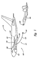
- Figure 1 is a partially schematic, isometric illustration of a tanker aircraft refueling a receiver aircraft in accordance with an embodiment of the invention.
- Figure 2 is a partially schematic illustration of a drogue that includes actuators and a guidance system configured in accordance with an embodiment of the invention.
- Figure 3 is a partially schematic, top isometric view of a representative receiver aircraft and drogue positioned for coupling in accordance with an embodiment of the invention.
- Figures 4A-4B are schematic illustrations of the drogue shown in Figure 2 with the vanes positioned to place a steering force on the drogue in accordance with embodiments of the invention.
- Figure 5 is a block diagram illustrating components of a system for guiding a refueling drogue in accordance with an embodiment of the invention.
- Figure 1 illustrates a system 110 that includes a tanker aircraft 100 positioned to couple with and refuel a receiver aircraft 104, using an aerial refueling device 120 configured in accordance with an embodiment of the invention.
- the tanker aircraft 100 has a fuselage 101, wings 102, and one or more engines 103 (two are shown in Figure 1 as being carried by the wings 102). In other embodiments, the aircraft 100 can have other configurations.
- the aerial refueling device 120 can include an on-board portion 122 (e.g., a hose reel activator and associated valving) and a deployable portion 121.
- the deployable portion 121 can include a hose 123 and a drogue 124.
- the position of the drogue 124 can be controlled in an automatic fashion to couple with a probe 105 of the receiver aircraft 104.
- the guidance system for effectuating this control can be carried entirely by the deployable portion 121 of the refueling device 120. Accordingly, not only can the process for coupling the drogue 124 to the receiver aircraft 104 be automated or at least partially automated, but the components that execute the automated process need not be carried on-board the tanker aircraft 100. This arrangement can simplify the tanker aircraft 100 and can significantly reduce the effort and expense required to retrofit the guidance system on an existing drogue-carrying tanker aircraft 100.
- FIG 2 is an enlarged, side isometric illustration of an embodiment of the drogue 124 described above with reference to Figure 1.
- the drogue 124 can include a coupling 225 that attaches the drogue 124 to the fuel hose 123.
- the drogue 124 can also include movable, overlapping vanes 226, and a canopy 227. When the vanes 226 are spread out from each other, the maximum diameter of the drogue 124 increases, and when the vanes 226 are drawn together, the maximum diameter of the drogue 124 decreases.
- the canopy 227 can operate like a donut-shaped parachute and can be filled by incoming air indicated by arrows A.
- the drogue 124 can have a generally streamlined shape suitable for high speed flight. If the canopy 227 is allowed to more fully inflate, the drogue 124 can be operated at lower flight speeds.
- the drogue 124 can include actuators 251 to control the motion of the vanes 226 and/or the canopy 227.
- the actuators 251 can include vane actuators 251 a and/or canopy actuators 251 b.
- the vane actuators 251 a can be attached between alternate vanes 226, and can be configured to extend or retract. Accordingly, when a particular vane actuator 251a retracts, it can pull two vanes 226a, 226b together relative to an intermediate vane 226c. When the vane actuators 251 a are extended, they can move the same two vanes 226a, 226b apart relative to the intermediate vane 226c.
- the canopy actuators 251 b can be attached to an inner and/or outer line of the canopy 227.
- the canopy 227 can be attached with a fixed line 228a to the outwardly facing surfaces of the vanes 226, and can be attached with variable length lines 228b to the inwardly facing surfaces of the vanes 226.
- the canopy actuators 251 b can also be attached to the variable length lines 228b and can move between an extended position and a retracted position.
- the canopy actuators 251 b can draw the canopy 227 more tightly around the vanes 226 (e.g., for a streamlined, high speed configuration), and when extended, the canopy actuators 251 b can allow the canopy to expand and inflate for a low speed configuration.
- a representative high speed configuration is identified by dashed lines H, and a representative low speed configuration is identified by dashed lines L.
- the motion of the actuators 251 can be controlled by a guidance system 240 and a control system 250 carried by the deployable portion 121 of the fuel delivery device 120.
- the guidance system 240 can receive information corresponding to the current state of the drogue 124 and, in at least some embodiments, a target state of the drogue 124.
- the guidance system 240 can provide instructions to the control system 250 that in turn directs the actuators 251 to drive the configuration of the drogue 124 from the current state to the target state.
- the guidance system 240 can be coupled to a sensor system 230 that includes one or more accelerometers 232, one or more gyros 233, and an image sensor 231.
- the accelerometer 232 and/or gyros 233 can provide information corresponding to the current motion of the drogue 124, and the image sensor 231 can provide information corresponding to the location of the drogue 231.
- the image sensor 231 can provide information corresponding to the location of the drogue 124 relative to a receiver aircraft that is approaching the drogue 231 for coupling. Further details of the interactions among the sensor system 230, the guidance system 240, the control system 250 and the actuators 251 are provided with reference to Figures 3-5.
- the deployable portion 121 of the fuel delivery device 120 can include a self-contained power system 260.
- the deployable portion 121 can include a wind turbine generator 261 (shown schematically in Figure 2) that provides power to the guidance system 240, the sensor system 230, the control system 250 and/or the actuators 251.
- the power system 260 can include other devices.
- Figure 3 illustrates the receiver aircraft 104 approaching the drogue 124 for coupling.
- the image sensor 231 carried by the drogue 124 can include a camera or other optical device that images the receiver aircraft 104.
- the image information received by the image sensor 231 can be used to provide one or more of the following functions.
- One function includes identifying the type of receiver aircraft 104 to which the drogue 124 will be coupled.
- the inherent features of the receiver aircraft 104 may be sufficient to allow such a determination.
- the receiver aircraft 104 can include one or more visual cue markings 306 that can be easily picked up and discriminated by the image sensor 231.
- the guidance system 240 can then be configured to compare the characteristics of the receiver aircraft 104 picked up by the image sensor 231 and compare them to a stored listing of known receiver aircraft characteristics. Using this technique, the guidance system 240 can identify the type of receiver aircraft 104 approaching the drogue 124.
- the aircraft identification function described above can be eliminated.
- the resolution capability of the image sensor 231 may be such that it need only image the end of the probe 105 (independent of what type of receiver aircraft the probe is attached to) to provide appropriate guidance information. This can be the case for different aircraft having the same or different probes 105.
- Another function that can be provided by the image sensor 231 includes providing information suitable for the guidance system 240 and control system 250 to steer the drogue 124 toward the probe 105 of the receiver aircraft 104. For example, if the data from image sensor 231 indicates that the probe 105 (or the visual cue markings 306) are off-center, then the guidance system 240 and control system 250 can steer the drogue 124 until it is centered on the probe 105. As described above, the sensor 231 can have a resolution capability sufficient to enable the steering function when used with probes 105 that may have different configurations.
- Figures 4A and 4B are schematic side isometric views of the drogue 124, and illustrate a representative manner by which the shape of the drogue 124 can be changed to move the drogue 124 in a particular direction.
- the drogue 124 can include upper vanes 126a and lower vanes 126b.
- the vane actuators 251 a can be actuated so as to draw the upper vanes 126a more closely together than the lower vanes 126b.
- the lower vanes 126b provide more frontal area to the free stream flow of air identified by arrows A.
- the relative spacings for the upper vanes 126a and the lower vanes 126b can be reversed to create a downward force F.
- a similar arrangement can be used to change the shape of the drogue 124 in a lateral direction (e.g., into and out of the plane of Figures 3A, 3B) and/or any intermediate direction.
- the drogue 124 can have an asymmetric shape relative to its major axis M. The asymmetric shape can be used to steer the drogue 124 in the pitch and yaw directions.
- Figure 5 is a block diagram illustrating representative components of the overall system 110 described above.
- Many components of the system 110 e.g., the guidance system 240 and the control system 250
- the system 110 can include a computer 544 having a processor 549, memory 548 and I/O devices 547.
- Functions provided by the computer 544 can be carried out by and/or supported by any of these or other components.
- Such functions include sensor processing carried out by a sensor processor 545.
- the sensor processor 545 can receive information from the sensor system 230, which can in turn include the accelerometer 232 (e.g., a Z-axis accelerometer), and one or more gyros 230 (e.g., a pitch rate gyro 233a, a roll rate gyro 233b, and a yaw rate gyro 233c).
- the sensor system 230 can further include an air speed sensor 536 and the image sensor 231 (e.g., a 3-D range image sensor). Accordingly, the guidance system 240 can compare the image data received from the image sensor 231 with data stored on an image database 543.
- Flight control laws 542 can be used to transform the difference between the current and target locations of the drogue into directives for the control system 250. Based on these directives, the control system 250 can issue commands to the actuators 251. When the actuators 251 receive the commands, they drive the drogue toward the target position, with feedback provided by the image sensor 231. The actuators 251 can also provide feedback to the control system 250 and the guidance system 240. For example, the actuators 251 can provide feedback information corresponding to the loads on the drogue. The information can in turn be used by the guidance system 240 to trim the loads on the drogue 124 ( Figure 2) to provide for smooth, stable flight of the drogue.
- One feature of an embodiment of the systems described above with reference to Figures 1-5 is that they can include the capability for automatically controlling the position of a refueling drogue beyond the positioning capability provided by simply changing the direction or speed of the tanker aircraft from which the drogue is deployed.
- An advantage of this capability is that it can reduce the workload required by the pilot of the receiver aircraft to successfully couple his or her aircraft with the drogue.
- the motion of the drogue can be fully automated. This can even further reduce the workload required by the pilot of the receiver aircraft. For example, in some cases, this arrangement can allow the receiver aircraft pilot to remain on station (in much the same manner as is currently used when refueling an aircraft via a refueling boom) while the guidance system automatically steers the drogue to a coupling position with the receiver aircraft, and trims the drogue so that it remains in a stable position.
- An advantage of this arrangement is that it can increase the likelihood for a successful coupling with the receiver aircraft, and can reduce the likelihood for damage to the receiver aircraft or the refueling system.
- the bow wave of the receiver aircraft can push the drogue away from the receiver aircraft every time the receiver aircraft gets close to the drogue.
- An embodiment of the foregoing automated system can automatically steer the drogue through the bow wave for a successful coupling.
- the guidance system can be entirely or nearly entirely independent of the receiver aircraft.
- the guidance system can be housed entirely on the deployable portion of the fuel delivery device, and need not receive guidance-related instructions or power from the receiver aircraft.
- the guidance system can receive power from an on-board power system, and, as a result of the closed loop arrangement with the image sensor, can provide a self-contained guidance function independent of the receiver aircraft.
- At least some communication can exist between the tanker aircraft and the guidance system, for example, to activate, deactivate, and/or override the guidance system, and/or to provide signals to the tanker refueling system that indicate when coupling is complete and/or when hose slack should be taken up.
- the guidance system can steer the drogue autonomously.
- Yet another feature of at least some of the foregoing embodiments is that they can include changing the shape and/or size of the drogue.
- the overall size of the drogue can be made larger or smaller, which can in turn make the drogue suitable for both low speed and high speed use.
- An advantage of this arrangement over existing arrangements is that the drogue need not be changed out when the tanker aircraft is required to refuel aircraft having different speeds when in a refueling. For example, by simply changing the shape of the drogue, the same drogue can be used to refuel helicopters, prop aircraft, and jet fighter aircraft, each of which has a different flight speed when located on station.
- the foregoing systems and methods can be used to change the shape of the drogue, e.g., in an asymmetric manner.
- An advantage of such shape changes is that they can enable the drogue to be steered into alignment with the receiver aircraft, and/or trimmed once in a desired position.
- the actuators can in some embodiments include electro-active polymer (EAP) actuators, to control the motion of the vanes and/or the canopy.
- EAP electro-active polymer
- Suitable actuators and designs are available from SRI International of Menlo Park, California.
- An advantage of EAP actuators is that they can apply a substantial force while remaining relatively small in size, and without requiring significant levels of power.
- the actuators can have other configurations.
- the guidance system can in some embodiments include a single-board microcomputer, or another suitable, lightweight, low volume device.
- the sensors can include solid state sensors (e.g., MEMS or micro-electro-mechanical systems) for the gyros and/or accelerometers.
- the image sensor can be a combination of a laser 3-D imager, a laser ranger, an optical proximity sensor, a visible-spectrum camera, and/or an infrared camera.
- the sensors and/or actuators can have arrangements different than those described above, while still providing data and controlling drogue movement in manners generally similar to those described above.
- some components of the system may be carried by the tanker aircraft without precluding the system from achieving at least some of the foregoing advantages.
- aspects of the sensor system (e.g., the image sensor) and/or the guidance system may be housed in the tanker aircraft, while still allowing the system to steer and/or trim the drogue via the actuated vanes and/or canopy.
- the refueling system can be installed on aircraft having configurations other than the tanker aircraft 100 shown in Figure 1, and can be used to refuel aircraft having configurations other than those of the receiver aircraft 104 shown in Figure 1.
- Aspects of the invention described in the context of particular embodiments may be combined or eliminated in other embodiments. Further, while advantages associated with certain embodiments of the invention have been described in the context of those embodiments, other embodiments may also exhibit such advantages, and not all embodiments need necessarily exhibit such advantages to fall within the scope of the invention. Accordingly, the invention is not limited except as by the appended claims.
Applications Claiming Priority (1)
| Application Number | Priority Date | Filing Date | Title |
|---|---|---|---|
| US11/157,245 US7219857B2 (en) | 2005-06-20 | 2005-06-20 | Controllable refueling drogues and associated systems and methods |
Publications (2)
| Publication Number | Publication Date |
|---|---|
| EP1736407A1 true EP1736407A1 (de) | 2006-12-27 |
| EP1736407B1 EP1736407B1 (de) | 2009-09-23 |
Family
ID=37054483
Family Applications (1)
| Application Number | Title | Priority Date | Filing Date |
|---|---|---|---|
| EP06253148A Active EP1736407B1 (de) | 2005-06-20 | 2006-06-16 | Steuerbare Luftbetankungs-Fangtrichter und zugehörige Systeme und Verfahren zur Betankung |
Country Status (4)
| Country | Link |
|---|---|
| US (2) | US7219857B2 (de) |
| EP (1) | EP1736407B1 (de) |
| AT (1) | ATE443657T1 (de) |
| DE (1) | DE602006009341D1 (de) |
Cited By (3)
| Publication number | Priority date | Publication date | Assignee | Title |
|---|---|---|---|---|
| GB2454512A (en) * | 2007-11-09 | 2009-05-13 | Flight Refueling Ltd | Steerable drogue for in-flight refuelling |
| CN102004454A (zh) * | 2009-08-31 | 2011-04-06 | 波音公司 | 用于控制加油锥套的方法和设备 |
| EP2952434A1 (de) * | 2014-06-03 | 2015-12-09 | Airbus Defence and Space SA | Luftbetankungskupplung zur Parametermessung im Flug |
Families Citing this family (36)
| Publication number | Priority date | Publication date | Assignee | Title |
|---|---|---|---|---|
| US7276433B2 (en) * | 2004-12-03 | 2007-10-02 | Micron Technology, Inc. | Methods of forming integrated circuitry, methods of forming memory circuitry, and methods of forming field effect transistors |
| US7581700B2 (en) * | 2005-06-09 | 2009-09-01 | The Boeing Company | Adjustable fittings for attaching support members to fluid conduits, including aircraft fuel conduits, and associated systems and methods |
| US7533850B2 (en) | 2005-06-09 | 2009-05-19 | The Boeing Company | Fittings with redundant seals for aircraft fuel lines, fuel tanks, and other systems |
| US7293741B2 (en) * | 2005-06-09 | 2007-11-13 | The Boeing Company | System and methods for distributing loads from fluid conduits, including aircraft fuel conduits |
| US7458543B2 (en) * | 2005-06-10 | 2008-12-02 | The Boeing Company | Aerial refueling system |
| US7219857B2 (en) * | 2005-06-20 | 2007-05-22 | The Boeing Company | Controllable refueling drogues and associated systems and methods |
| US7472868B2 (en) * | 2005-09-01 | 2009-01-06 | The Boeing Company | Systems and methods for controlling an aerial refueling device |
| US20070102583A1 (en) * | 2005-10-26 | 2007-05-10 | Cutler Theron L | Systems and methods for reducing surge loads in hose assemblies, including aircraft refueling hose assemblies |
| US9090354B2 (en) * | 2006-03-02 | 2015-07-28 | The Boeing Company | System and method for identifying a receiving aircraft during airborne fueling |
| GB0613386D0 (en) * | 2006-07-05 | 2006-08-16 | Flight Refueling Ltd | A drogue assembly for in-flight refuelling |
| WO2009091792A2 (en) * | 2008-01-15 | 2009-07-23 | Sysense, Inc. | A methodology for autonomous navigation and control of a tethered drogue |
| US7938369B2 (en) * | 2008-01-22 | 2011-05-10 | The Boeing Company | Method and apparatus for aerial fuel transfer |
| FR2931451B1 (fr) * | 2008-05-22 | 2010-12-17 | Fmc Technologies Sa | Dispositif de commande pour systeme de chargement et/ou dechargement de fluides |
| US8162261B2 (en) * | 2008-11-05 | 2012-04-24 | The Boeing Company | Self contained power system for controllable refueling drogues |
| US8232706B2 (en) | 2009-01-09 | 2012-07-31 | The Boeing Company | Autonomous power generation unit for auxiliary system on an airborne platform |
| US20100217526A1 (en) * | 2009-02-26 | 2010-08-26 | Lockheed Martin Corporation | Method for simple optical autonomous refueling system |
| US8567723B2 (en) * | 2009-04-08 | 2013-10-29 | The Boeing Company | Automated receiver aircraft identification (ARAI) for in-flight refueling |
| US8220746B1 (en) | 2009-05-29 | 2012-07-17 | The Boeing Company | Broad speed range inflatable drogue canopy |
| US8317136B2 (en) * | 2009-07-06 | 2012-11-27 | West Coast Netting, Inc. | Stabilized controllable drogue for aerial flight refueling |
| US8439311B2 (en) | 2010-08-23 | 2013-05-14 | The Boeing Company | Aerial refueling boom and boom pivot |
| US9150310B1 (en) * | 2010-09-10 | 2015-10-06 | The Boeing Company | Methods and systems for directing remote aerial refueling operations |
| US8398028B1 (en) * | 2010-11-16 | 2013-03-19 | The Boeing Company | Drogue with power generator |
| US8561947B2 (en) | 2011-01-05 | 2013-10-22 | Ge Aviation Systems, Llc | Method and system for a refueling drogue assembly |
| US9896214B1 (en) * | 2011-02-18 | 2018-02-20 | Twist, Inc. | Hose movement sensor |
| US9469410B2 (en) * | 2011-07-22 | 2016-10-18 | Carleton Life Support Systems Inc. | Aerial refueling system, apparatus and methods |
| GB2500669B (en) * | 2012-03-29 | 2016-03-30 | Icon Polymer Group | Hose for conveying fluid |
| US20160252351A1 (en) * | 2015-02-27 | 2016-09-01 | Ge Aviation Systems Llc | System and methods for providing situational awareness information for a relative navigation system |
| ES2584231B2 (es) * | 2015-10-09 | 2017-06-02 | Defensya Ingeniería Internacional, S.L. | Sistema de localización del extremo del boom, de la boca del receptáculo de repostaje y del tanquero |
| US10618668B2 (en) | 2016-09-06 | 2020-04-14 | Analytical Mechanics Associates, Inc. | Systems and apparatus for controlling movement of objects through a fluid |
| US10703501B2 (en) | 2017-03-17 | 2020-07-07 | Analytical Mechanics Associates, Inc. | Drogue control systems and apparatus |
| US11124314B2 (en) | 2018-04-12 | 2021-09-21 | The Boeing Company | Systems and methods for transferring electric power to an aircraft during flight |
| US11254440B2 (en) * | 2019-08-07 | 2022-02-22 | Rockwell Collins, Inc. | Relative navigation and machine vision for automated aerial refueling system and method |
| US11338892B2 (en) | 2019-11-14 | 2022-05-24 | Textron Innovations Inc. | Autonomous seabased resupply system |
| US11005301B1 (en) | 2020-01-10 | 2021-05-11 | The Boeing Company | System and method for encrypted resonant inductive power transfer |
| GB2593694A (en) * | 2020-03-30 | 2021-10-06 | Cobham Mission Systems Wimborne Ltd | Drogue assembly for air-to-air engagement |
| US11866192B2 (en) | 2021-04-29 | 2024-01-09 | Sky Launch Corporation | System and method for reconnectably coupling an AFT vehicle to a forward vehicle in flight |
Citations (3)
| Publication number | Priority date | Publication date | Assignee | Title |
|---|---|---|---|---|
| WO1991006471A1 (en) * | 1989-10-27 | 1991-05-16 | Gec-Marconi Limited | Refueling apparatus |
| WO2002055385A1 (en) * | 2001-01-13 | 2002-07-18 | Bae Systems Plc | A drogue for in-flight refuelling |
| GB2405384A (en) * | 2003-08-29 | 2005-03-02 | Smiths Aerospace Inc | Stabilization of a drogue body, aircraft, or marine vessel |
Family Cites Families (137)
| Publication number | Priority date | Publication date | Assignee | Title |
|---|---|---|---|---|
| US724675A (en) * | 1902-08-29 | 1903-04-07 | William M Ferry | Fluid-conducting pipe. |
| GB374873A (en) | 1931-03-11 | 1932-06-13 | Richard Howard Halbeard | Improvements in or relating to cisterns or other tanks |
| US2091916A (en) * | 1936-04-27 | 1937-08-31 | Hughes Tool Co | Pipe clamp |
| US2213680A (en) * | 1939-12-08 | 1940-09-03 | Share Barnett | Valve for well point systems |
| GB555984A (en) | 1942-03-10 | 1943-09-15 | Fireproof Tanks Ltd | Improvements in or relating to tanks for petrol or other liquids |
| US2414509A (en) * | 1944-06-02 | 1947-01-21 | Lockheed Aircraft Corp | Bulkhead mounting for conduits |
| US2453553A (en) * | 1944-07-28 | 1948-11-09 | Leslie R Tansley | Measuring valve mechanism |
| US2475635A (en) * | 1945-01-08 | 1949-07-12 | Elmer C Parsons | Multiple conduit |
| US2552991A (en) * | 1948-04-16 | 1951-05-15 | South Hosuton Machine Company | Valve assembly |
| US2953332A (en) * | 1950-03-31 | 1960-09-20 | Flight Refueling Ltd | Apparatus for towing and refuelling aircraft in flight |
| US2670913A (en) * | 1950-04-24 | 1954-03-02 | Boeing Co | Aircraft boom control and balancing mechanism |
| US2668066A (en) * | 1951-02-10 | 1954-02-02 | Berkeley Pump Company | Coupling means for tubular casing |
| US2859002A (en) * | 1954-03-05 | 1958-11-04 | Boeing Co | Airfoil aircraft interconnecting boom |
| US2879017A (en) | 1955-01-25 | 1959-03-24 | Flight Refueling Inc | Apparatus for interconnecting aircraft in flight |
| US2954190A (en) | 1955-03-07 | 1960-09-27 | Parker Hannifin Corp | Hose reel and control mechanism therefor |
| US2919937A (en) * | 1956-07-30 | 1960-01-05 | Federal Mogul Bower Bearings | Pipe coupling having inflated sealing means |
| US2960295A (en) * | 1956-09-11 | 1960-11-15 | Boeing Co | Simplified aircraft boom control mechanism |
| US3091419A (en) | 1957-01-14 | 1963-05-28 | Schulz Tool & Mfg Co | Aircraft in-flight refueling system |
| US2973171A (en) * | 1957-01-15 | 1961-02-28 | Flight Refueling Inc | In-flight connection for aircraft |
| US2946543A (en) * | 1957-01-25 | 1960-07-26 | Textron Inc | Aerodynamic drag device |
| US2941761A (en) * | 1957-08-22 | 1960-06-21 | Textron Inc | Guidance system for aerial refueling |
| US3061246A (en) * | 1957-12-23 | 1962-10-30 | Vitro Corp Of America | Flying pipe refueling system |
| US2967684A (en) | 1958-12-31 | 1961-01-10 | Robert S Knecht | Combination inflight refueling and dumping for helicopters |
| US3108769A (en) * | 1961-09-18 | 1963-10-29 | Schulz Tool & Mfg Co | Ring wing drogue |
| US3112763A (en) | 1962-04-12 | 1963-12-03 | Hydraulic Unit Specialities Co | Combined high pressure relief and void control valve |
| FR2082386A5 (de) | 1970-03-12 | 1971-12-10 | Inst Francais Du Petrole | |
| US3747873A (en) * | 1971-11-19 | 1973-07-24 | Susquehanna Corp | Tow cable assembly |
| US3836117A (en) * | 1973-03-20 | 1974-09-17 | M Panicali | Valve cap |
| US4090524A (en) | 1974-02-11 | 1978-05-23 | Aeroquip Corporation | Frangible valved fitting |
| US3917196A (en) | 1974-02-11 | 1975-11-04 | Boeing Co | Apparatus suitable for use in orienting aircraft flight for refueling or other purposes |
| US3928903A (en) * | 1975-01-29 | 1975-12-30 | Atlantic Richfield Co | Method of making a double-walled pipe assembly |
| US4044834A (en) * | 1975-04-09 | 1977-08-30 | Perkins Lee E | Apparatus and method for controlling the flow of fluids from a well bore |
| DE2544001A1 (de) * | 1975-10-02 | 1977-04-07 | Schneider Co Optische Werke | Druckventil |
| US4095761A (en) * | 1976-09-29 | 1978-06-20 | The Boeing Company | Aerial refueling spoiler |
| US4072283A (en) * | 1976-12-17 | 1978-02-07 | The Boeing Company | Aerial refueling boom articulation |
| US4149739A (en) * | 1977-03-18 | 1979-04-17 | Summa Corporation | Dual passage pipe for cycling water to an undersea mineral aggregate gathering apparatus |
| SU673798A1 (ru) | 1977-05-16 | 1979-07-15 | Nikitenko Vitalij A | Опора трубопроводов |
| US4129270A (en) * | 1977-06-13 | 1978-12-12 | The Boeing Company | Air refueling boom pivot gimbal arrangements |
| DE2744674A1 (de) | 1977-10-04 | 1979-04-05 | Wilhelm Schulz | Flanschverbindung |
| US4150803A (en) * | 1977-10-05 | 1979-04-24 | Fernandez Carlos P | Two axes controller |
| US4231536A (en) * | 1977-10-11 | 1980-11-04 | The Boeing Company | Airfoil for controlling refueling boom |
| US4236686A (en) | 1978-09-07 | 1980-12-02 | Grumman Aerospace Corporation | Ship compatible launch, retrieval and handling system for (VTOL) aircraft |
| US4477040A (en) * | 1978-10-19 | 1984-10-16 | Grumman Aerospace Corporation | Aircraft wind energy device |
| US4586683A (en) * | 1979-03-12 | 1986-05-06 | Mcdonnell Douglas Corporation | Rolling aerial refueling boom |
| US4340079A (en) | 1980-02-15 | 1982-07-20 | Grove Valve And Regulator Company | Energy dissipating pipeline surge relief system |
| US4327784A (en) * | 1980-06-09 | 1982-05-04 | Rockwell International Corporation | Apparatus for refueling an aircraft from a ship at sea |
| SU953345A1 (ru) | 1981-01-21 | 1982-08-23 | Предприятие П/Я А-7976 | Опора дл закреплени трубопроводов,подвешенна к каркасу |
| US4408943A (en) * | 1981-02-27 | 1983-10-11 | Fmc Corporation | Ship-to-ship fluid transfer system |
| US4438793A (en) * | 1981-05-04 | 1984-03-27 | International Telephone & Telegraph Corp. | Aerial refueling boom nozzle |
| DE3126041C2 (de) * | 1981-07-02 | 1985-11-28 | Danfoss A/S, Nordborg | Hydraulische Steuervorrichtung mit einer verstellbaren Drossel |
| IT8252814V0 (it) | 1982-01-13 | 1982-01-13 | Borletti Spa | Gruppo di chiusura a tenuta di un foro di un serbatoio |
| US4534384A (en) * | 1982-12-15 | 1985-08-13 | Flight Refueling, Inc. | Reel system for axially extending hose |
| EP0236584B1 (de) | 1986-03-14 | 1990-08-08 | The Boeing Company | Bordseitiger Heckstützheberzusammenbau |
| AT391932B (de) | 1983-10-31 | 1990-12-27 | Wolf Erich M | Rohrleitung |
| CH669856A5 (de) * | 1984-01-04 | 1989-04-14 | Lonza Ag | |
| US4540144A (en) * | 1984-01-05 | 1985-09-10 | United Technologies Corporation | Telescoping fuel probe |
| USH297H (en) | 1985-08-12 | 1987-07-07 | The United States Of America As Represented By The Secretary Of The Air Force | Robotic refueling system for tactical and strategic aircraft |
| US4717099A (en) * | 1986-05-15 | 1988-01-05 | Hubbard George R | Fire sprinkler alignment bracket |
| US4883102A (en) * | 1987-02-18 | 1989-11-28 | Mher Gabrielyan | Drain line apparatus |
| US4796838A (en) * | 1988-01-14 | 1989-01-10 | The United States Of America As Represented By The Secretary Of The Air Force | Hose reel monitor for inflight refueling system |
| US5141178A (en) * | 1988-02-19 | 1992-08-25 | Whittaker Controls, Inc. | Aerial refueling system |
| DE3936198A1 (de) | 1988-11-02 | 1990-05-17 | Raimund Hoellein Carolinenhuet | Aufhaengevorrichtung fuer an bruecken zu befestigende rohre |
| US4929000A (en) * | 1988-12-02 | 1990-05-29 | American Metal Products Company | Multiple walled chimney |
| NO170650C (no) | 1990-03-19 | 1992-11-11 | Holta & Haaland As | Festeklammer |
| US5131438A (en) * | 1990-08-20 | 1992-07-21 | E-Systems, Inc. | Method and apparatus for unmanned aircraft in flight refueling |
| US5449203A (en) * | 1991-04-04 | 1995-09-12 | Sharp; Bruce R. | Fittings for connection to double wall pipeline systems |
| US5326052A (en) | 1991-10-02 | 1994-07-05 | Enig Associates, Inc. | Controllable hose-and-drogue in-flight refueling system |
| CA2147165C (en) | 1992-10-17 | 2005-06-21 | George Albert Lees | Branch-off connection |
| US5427333A (en) * | 1992-10-21 | 1995-06-27 | West Coast Netting, Inc. | Variable speed drogue |
| US5255877A (en) * | 1992-10-21 | 1993-10-26 | West Coast Netting, Inc. | Variable speed drogue |
| US5530650A (en) * | 1992-10-28 | 1996-06-25 | Mcdonnell Douglas Corp. | Computer imaging system and method for remote in-flight aircraft refueling |
| FR2705082B1 (fr) | 1993-05-12 | 1995-08-04 | Aerospatiale | Système de ravitaillement en vol. |
| US5393015A (en) * | 1993-06-01 | 1995-02-28 | Piasecki Aircraft Corporation | Rotary wing aircraft in-flight refueling device |
| US5449204A (en) * | 1993-10-22 | 1995-09-12 | Greene; Karen C. | Double containment fitting |
| RU2142897C1 (ru) | 1994-08-19 | 1999-12-20 | Анатолий Викторович Егоршев | Самолет-заправщик |
| US5573206A (en) * | 1994-08-19 | 1996-11-12 | Able Corporation | Hose and drogue boom refueling system, for aircraft |
| US5539624A (en) * | 1995-01-17 | 1996-07-23 | Durodyne, Inc. | Illuminated hose |
| GB2298908A (en) | 1995-03-15 | 1996-09-18 | Ford Motor Co | Fuel tank tubular fittings |
| US5785276A (en) * | 1995-12-22 | 1998-07-28 | The Boeing Company | Actuated roll axis aerial refueling boom |
| FR2748450B1 (fr) * | 1996-05-10 | 1998-08-14 | Sextant Avionique | Procede et dispositif de guidage d'une perche de ravitaillement en vol |
| US5810292A (en) * | 1996-07-24 | 1998-09-22 | Sargent Fletcher, Inc. | Aerial refueling system with telescoping refueling probe |
| TW386966B (en) | 1996-07-24 | 2000-04-11 | Sargent Fletcher Inc | Aerial refueling system with telescopic refueling probe |
| US5904729A (en) * | 1997-03-04 | 1999-05-18 | The Boeing Company | Automated director light system for aerial refueling operations |
| US6119981A (en) * | 1997-03-04 | 2000-09-19 | Flight Refuelling Limited | Drogue assembly for in-flight refuelling |
| US6145788A (en) * | 1997-05-27 | 2000-11-14 | Flight Refueling Limited | Drogue assembly for in-flight refueling |
| DE29710006U1 (de) * | 1997-06-09 | 1998-11-05 | Buerkert Werke Gmbh & Co | Miniaturisierte Ventileinrichtung |
| RU2111154C1 (ru) | 1997-06-11 | 1998-05-20 | Виктор Александрович Бублик | Устройство контроля заправки самолета топливом в полете |
| TW333684B (en) * | 1997-09-24 | 1998-06-11 | Nanya Technology Co Ltd | The producing method for semiconductor capacitor electrode plate |
| US5906336A (en) * | 1997-11-14 | 1999-05-25 | Eckstein; Donald | Method and apparatus for temporarily interconnecting an unmanned aerial vehicle |
| RU2140381C1 (ru) | 1997-12-10 | 1999-10-27 | Акционерное общество открытого типа "ОКБ Сухого" | Самолетная система дозаправки другого самолета |
| NL1007899C2 (nl) * | 1997-12-24 | 1999-06-25 | Dhv Water Bv | Koppelelement voor membraanelementen. |
| US6142421A (en) | 1998-01-13 | 2000-11-07 | Science Applications International Corporation | Vehicle refueling system |
| US5921294A (en) * | 1998-03-04 | 1999-07-13 | The United States Of America As Represented By The Secretary Of The Navy | Air refueling drogue |
| DE19831520A1 (de) * | 1998-07-14 | 2000-01-20 | Schaeffler Waelzlager Ohg | Elektromagnetischer Ventiltrieb |
| US5996939A (en) * | 1998-08-28 | 1999-12-07 | The Boeing Company | Aerial refueling boom with translating pivot |
| IT244388Y1 (it) * | 1998-11-23 | 2002-03-11 | Nupi S P A | Raccordi per tubi a doppia parete |
| DE29901583U1 (de) | 1999-01-29 | 1999-05-12 | Hesterberg Gmbh | Höhenverstellbare Rohrhalterung |
| IL128459A (en) | 1999-02-09 | 2003-05-29 | Boeing Co | Automated director light system for aerial refueling operations |
| GB9910393D0 (en) * | 1999-05-05 | 1999-07-07 | Lucas Ind Plc | Electrical generator,an aero-engine including such a generator and an aircraft including such a generator |
| JP3872230B2 (ja) * | 1999-05-07 | 2007-01-24 | 株式会社日立製作所 | 吸排気弁の電磁駆動装置 |
| US6464173B1 (en) * | 1999-09-30 | 2002-10-15 | Sargent Fletcher, Inc. | Paradrogue assembly |
| DE10013751A1 (de) | 2000-03-20 | 2001-10-11 | Schmidt Schieferstein Herrmann | Universelles Luftbetankungssystem |
| US6866228B2 (en) | 2000-07-21 | 2005-03-15 | Asher Bartov | Aerial refueling hose reel drive controlled by a variable displacement hydraulic motor and method for controlling aerial refueling hose reel |
| US6454212B1 (en) * | 2000-08-22 | 2002-09-24 | Asher Bartov | Aerial refueling hose reel drive controlled by a variable displacement hydraulic motor and method for controlling aerial refueling hose reel |
| US6375123B1 (en) * | 2000-08-15 | 2002-04-23 | The United States Of America As Represented By The Secretary Of The Navy | Air refueling drogue |
| US7921442B2 (en) * | 2000-08-16 | 2011-04-05 | The Boeing Company | Method and apparatus for simultaneous live television and data services using single beam antennas |
| US6601800B2 (en) * | 2000-09-19 | 2003-08-05 | Charles Howard Ollar | Aerial refueling pod and constant tension line apparatus |
| US6604711B1 (en) * | 2000-11-20 | 2003-08-12 | Sargent Fletcher, Inc. | Autonomous system for the aerial refueling or decontamination of unmanned airborne vehicles |
| GB2373488A (en) | 2001-03-21 | 2002-09-25 | Bae Systems Plc | Launching, refuelling and recovering an aircraft |
| FR2825815B1 (fr) * | 2001-06-08 | 2003-08-22 | Thales Sa | Procede de gestion du ravitaillement en vol d'une flotille d'aeronefs |
| FR2827346B1 (fr) | 2001-07-12 | 2003-12-26 | Messier Bugatti | Architecture de circuit hydraulique |
| US20030038821A1 (en) * | 2001-08-27 | 2003-02-27 | Kraft Joshua Dickinson | Computer controlled interactive touch display pad with transparent full character keyboard overlaying displayed text and graphics |
| US6796527B1 (en) * | 2001-09-20 | 2004-09-28 | Hamilton Sundstrand Corporation | Integrated air turbine driven system for providing aircraft environmental control |
| US6676379B2 (en) * | 2001-12-06 | 2004-01-13 | Honeywell International Inc. | Ram air turbine with speed increasing gearbox |
| US20030136874A1 (en) * | 2001-12-10 | 2003-07-24 | Gjerdrum David Michael | Method for safer mid-air refueling |
| US6655136B2 (en) | 2001-12-21 | 2003-12-02 | Caterpillar Inc | System and method for accumulating hydraulic fluid |
| US6588465B1 (en) * | 2002-01-15 | 2003-07-08 | West Coast Netting, Inc. | Passive variable speed drogue |
| US6651933B1 (en) * | 2002-05-01 | 2003-11-25 | The Boeing Company | Boom load alleviation using visual means |
| US6658329B1 (en) | 2002-05-02 | 2003-12-02 | The United States Of America As Represented By The United States National Aeronautics And Space Administration | Video guidance sensor system with laser rangefinder |
| US6779758B2 (en) * | 2002-05-07 | 2004-08-24 | Smiths Aerospace, Inc. | Boom deploy system |
| US6752357B2 (en) * | 2002-05-10 | 2004-06-22 | The Boeing Company | Distance measuring using passive visual means |
| US6598830B1 (en) * | 2002-06-12 | 2003-07-29 | Sikorsky Aircraft Corporation | Telescoping refueling probe |
| US6848720B2 (en) * | 2002-08-09 | 2005-02-01 | The Boeing Company | Shrouded fluid-conducting apparatus |
| US6819982B2 (en) * | 2002-11-26 | 2004-11-16 | The Boeing Company | Uninhabited airborne vehicle in-flight refueling system |
| US6669145B1 (en) * | 2002-12-30 | 2003-12-30 | The Boeing Company | Apparatus, method and system for fluid-motion-powered modulation of a retroreflector for remote position sensing |
| US6960750B2 (en) * | 2003-01-08 | 2005-11-01 | The Boeing Company | Optical positioning system and method, transceiver, and reflector |
| US7024309B2 (en) * | 2003-08-28 | 2006-04-04 | The United States Of America As Represented By The Secretary Of The Air Force | Autonomous station keeping system for formation flight |
| US7093801B2 (en) | 2004-05-28 | 2006-08-22 | The Boeing Company | Positioning system, device, and method for in-flight refueling |
| US7281687B2 (en) | 2004-07-14 | 2007-10-16 | The Boeing Company | In-flight refueling system and method for facilitating emergency separation of in-flight refueling system components |
| US7097139B2 (en) * | 2004-07-22 | 2006-08-29 | The Boeing Company | In-flight refueling system, damping device and method for damping oscillations in in-flight refueling system components |
| US7380754B2 (en) * | 2004-09-30 | 2008-06-03 | The Boeing Company | Clamp block assemblies and methods |
| US7309047B2 (en) | 2005-02-25 | 2007-12-18 | The Boeing Company | Systems and methods for controlling flexible communication links used for aircraft refueling |
| US7188807B2 (en) | 2005-03-11 | 2007-03-13 | The Boeing Company | Refueling booms with multiple couplings and associated methods and systems |
| US7213787B2 (en) * | 2005-06-07 | 2007-05-08 | The Boeing Company | Valves for annular conduits including aircraft fuel conduits and associated systems and methods |
| US7533850B2 (en) | 2005-06-09 | 2009-05-19 | The Boeing Company | Fittings with redundant seals for aircraft fuel lines, fuel tanks, and other systems |
| US7293741B2 (en) * | 2005-06-09 | 2007-11-13 | The Boeing Company | System and methods for distributing loads from fluid conduits, including aircraft fuel conduits |
| US7219857B2 (en) | 2005-06-20 | 2007-05-22 | The Boeing Company | Controllable refueling drogues and associated systems and methods |
-
2005
- 2005-06-20 US US11/157,245 patent/US7219857B2/en active Active
-
2006
- 2006-06-16 EP EP06253148A patent/EP1736407B1/de active Active
- 2006-06-16 AT AT06253148T patent/ATE443657T1/de not_active IP Right Cessation
- 2006-06-16 DE DE602006009341T patent/DE602006009341D1/de active Active
-
2007
- 2007-05-22 US US11/752,156 patent/US7887010B2/en active Active
Patent Citations (3)
| Publication number | Priority date | Publication date | Assignee | Title |
|---|---|---|---|---|
| WO1991006471A1 (en) * | 1989-10-27 | 1991-05-16 | Gec-Marconi Limited | Refueling apparatus |
| WO2002055385A1 (en) * | 2001-01-13 | 2002-07-18 | Bae Systems Plc | A drogue for in-flight refuelling |
| GB2405384A (en) * | 2003-08-29 | 2005-03-02 | Smiths Aerospace Inc | Stabilization of a drogue body, aircraft, or marine vessel |
Cited By (8)
| Publication number | Priority date | Publication date | Assignee | Title |
|---|---|---|---|---|
| GB2454512A (en) * | 2007-11-09 | 2009-05-13 | Flight Refueling Ltd | Steerable drogue for in-flight refuelling |
| GB2454593A (en) * | 2007-11-09 | 2009-05-13 | Flight Refueling Ltd | Steerable drogue for in-flight refuelling |
| WO2009060224A1 (en) | 2007-11-09 | 2009-05-14 | Flight Refuelling Limited | Steerable drogue |
| CN102004454A (zh) * | 2009-08-31 | 2011-04-06 | 波音公司 | 用于控制加油锥套的方法和设备 |
| CN102004454B (zh) * | 2009-08-31 | 2015-05-20 | 波音公司 | 用于控制加油锥套的方法、设备以及加油系统 |
| EP2289800A3 (de) * | 2009-08-31 | 2016-04-27 | The Boeing Company | Verfahren und Vorrichtung zur Steuerung eines Betankungsfangtrichters |
| EP2952434A1 (de) * | 2014-06-03 | 2015-12-09 | Airbus Defence and Space SA | Luftbetankungskupplung zur Parametermessung im Flug |
| US9731835B2 (en) | 2014-06-03 | 2017-08-15 | Eads Construcciones Aeronáuticas, S.A. | Aerial refueling coupling for in-flight operation parameter measuring |
Also Published As
| Publication number | Publication date |
|---|---|
| DE602006009341D1 (de) | 2009-11-05 |
| EP1736407B1 (de) | 2009-09-23 |
| US7887010B2 (en) | 2011-02-15 |
| US7219857B2 (en) | 2007-05-22 |
| US20060284019A1 (en) | 2006-12-21 |
| US20080054124A1 (en) | 2008-03-06 |
| ATE443657T1 (de) | 2009-10-15 |
Similar Documents
| Publication | Publication Date | Title |
|---|---|---|
| EP1736407B1 (de) | Steuerbare Luftbetankungs-Fangtrichter und zugehörige Systeme und Verfahren zur Betankung | |
| US10800546B2 (en) | Unmanned aerial vehicle (UAV) and system and method for capture of threat UAVs | |
| US8028952B2 (en) | System for shipboard launch and recovery of unmanned aerial vehicle (UAV) aircraft and method therefor | |
| EP3294630B1 (de) | Verwendung einer plattform eines unbemannten luftfahrzeugs mit einer drehscheibenanordnung | |
| AU2013261044B2 (en) | Point take-off and landing of unmanned flying objects | |
| US8162256B2 (en) | Launch and capture systems for vertical take-off and landing (VTOL) vehicles | |
| EP1705116B1 (de) | System und Verfahren zur automatischen oder halbautomatischen Kontrolle der Betankung eines Flugzeuges während des Fluges | |
| KR102157089B1 (ko) | 비행체들을 재급유하는 디바이스들, 시스템들 및 방법들 | |
| US4753400A (en) | Shipboard air vehicle retrieval apparatus | |
| US10654584B2 (en) | Refueling system and method | |
| US9315277B2 (en) | System and method for transferring fuel in flight from a tanker aircraft to multiple receiver aircraft | |
| US20180086434A1 (en) | An Aircraft for Aerial Delivery | |
| EP3642114B1 (de) | System und verfahren zum auftanken von flugzeugen | |
| WO2007086055A1 (en) | Aircraft landing method, system and device | |
| EP3680181A1 (de) | Kabelgestützter punktstart und kabelgestützte landung von unbemannten flugobjekten | |
| WO2006085986A1 (en) | In-flight refueling system, boom, and method for extending range of motion of an in-flight refueling boom | |
| US20160075441A1 (en) | Aerial refueling navigable device, system and method | |
| US20240017857A1 (en) | Systems and methods for airborne recovery and launch of aerial vehicles |
Legal Events
| Date | Code | Title | Description |
|---|---|---|---|
| PUAI | Public reference made under article 153(3) epc to a published international application that has entered the european phase |
Free format text: ORIGINAL CODE: 0009012 |
|
| 17P | Request for examination filed |
Effective date: 20060622 |
|
| AK | Designated contracting states |
Kind code of ref document: A1 Designated state(s): AT BE BG CH CY CZ DE DK EE ES FI FR GB GR HU IE IS IT LI LT LU LV MC NL PL PT RO SE SI SK TR |
|
| AX | Request for extension of the european patent |
Extension state: AL BA HR MK YU |
|
| 17Q | First examination report despatched |
Effective date: 20070308 |
|
| AKX | Designation fees paid |
Designated state(s): AT BE BG CH CY CZ DE DK EE ES FI FR GB GR HU IE IS IT LI LT LU LV MC NL PL PT RO SE SI SK TR |
|
| GRAP | Despatch of communication of intention to grant a patent |
Free format text: ORIGINAL CODE: EPIDOSNIGR1 |
|
| GRAS | Grant fee paid |
Free format text: ORIGINAL CODE: EPIDOSNIGR3 |
|
| GRAA | (expected) grant |
Free format text: ORIGINAL CODE: 0009210 |
|
| AK | Designated contracting states |
Kind code of ref document: B1 Designated state(s): AT BE BG CH CY CZ DE DK EE ES FI FR GB GR HU IE IS IT LI LT LU LV MC NL PL PT RO SE SI SK TR |
|
| REG | Reference to a national code |
Ref country code: GB Ref legal event code: FG4D |
|
| REG | Reference to a national code |
Ref country code: CH Ref legal event code: EP |
|
| REG | Reference to a national code |
Ref country code: IE Ref legal event code: FG4D |
|
| REF | Corresponds to: |
Ref document number: 602006009341 Country of ref document: DE Date of ref document: 20091105 Kind code of ref document: P |
|
| PG25 | Lapsed in a contracting state [announced via postgrant information from national office to epo] |
Ref country code: LT Free format text: LAPSE BECAUSE OF FAILURE TO SUBMIT A TRANSLATION OF THE DESCRIPTION OR TO PAY THE FEE WITHIN THE PRESCRIBED TIME-LIMIT Effective date: 20090923 Ref country code: SE Free format text: LAPSE BECAUSE OF FAILURE TO SUBMIT A TRANSLATION OF THE DESCRIPTION OR TO PAY THE FEE WITHIN THE PRESCRIBED TIME-LIMIT Effective date: 20090923 Ref country code: FI Free format text: LAPSE BECAUSE OF FAILURE TO SUBMIT A TRANSLATION OF THE DESCRIPTION OR TO PAY THE FEE WITHIN THE PRESCRIBED TIME-LIMIT Effective date: 20090923 |
|
| LTIE | Lt: invalidation of european patent or patent extension |
Effective date: 20090923 |
|
| PG25 | Lapsed in a contracting state [announced via postgrant information from national office to epo] |
Ref country code: LV Free format text: LAPSE BECAUSE OF FAILURE TO SUBMIT A TRANSLATION OF THE DESCRIPTION OR TO PAY THE FEE WITHIN THE PRESCRIBED TIME-LIMIT Effective date: 20090923 Ref country code: PL Free format text: LAPSE BECAUSE OF FAILURE TO SUBMIT A TRANSLATION OF THE DESCRIPTION OR TO PAY THE FEE WITHIN THE PRESCRIBED TIME-LIMIT Effective date: 20090923 Ref country code: SI Free format text: LAPSE BECAUSE OF FAILURE TO SUBMIT A TRANSLATION OF THE DESCRIPTION OR TO PAY THE FEE WITHIN THE PRESCRIBED TIME-LIMIT Effective date: 20090923 |
|
| NLV1 | Nl: lapsed or annulled due to failure to fulfill the requirements of art. 29p and 29m of the patents act | ||
| PG25 | Lapsed in a contracting state [announced via postgrant information from national office to epo] |
Ref country code: CY Free format text: LAPSE BECAUSE OF FAILURE TO SUBMIT A TRANSLATION OF THE DESCRIPTION OR TO PAY THE FEE WITHIN THE PRESCRIBED TIME-LIMIT Effective date: 20090923 |
|
| PG25 | Lapsed in a contracting state [announced via postgrant information from national office to epo] |
Ref country code: RO Free format text: LAPSE BECAUSE OF FAILURE TO SUBMIT A TRANSLATION OF THE DESCRIPTION OR TO PAY THE FEE WITHIN THE PRESCRIBED TIME-LIMIT Effective date: 20090923 Ref country code: IS Free format text: LAPSE BECAUSE OF FAILURE TO SUBMIT A TRANSLATION OF THE DESCRIPTION OR TO PAY THE FEE WITHIN THE PRESCRIBED TIME-LIMIT Effective date: 20100123 Ref country code: PT Free format text: LAPSE BECAUSE OF FAILURE TO SUBMIT A TRANSLATION OF THE DESCRIPTION OR TO PAY THE FEE WITHIN THE PRESCRIBED TIME-LIMIT Effective date: 20100125 Ref country code: CZ Free format text: LAPSE BECAUSE OF FAILURE TO SUBMIT A TRANSLATION OF THE DESCRIPTION OR TO PAY THE FEE WITHIN THE PRESCRIBED TIME-LIMIT Effective date: 20090923 Ref country code: ES Free format text: LAPSE BECAUSE OF FAILURE TO SUBMIT A TRANSLATION OF THE DESCRIPTION OR TO PAY THE FEE WITHIN THE PRESCRIBED TIME-LIMIT Effective date: 20100103 Ref country code: EE Free format text: LAPSE BECAUSE OF FAILURE TO SUBMIT A TRANSLATION OF THE DESCRIPTION OR TO PAY THE FEE WITHIN THE PRESCRIBED TIME-LIMIT Effective date: 20090923 |
|
| PG25 | Lapsed in a contracting state [announced via postgrant information from national office to epo] |
Ref country code: SK Free format text: LAPSE BECAUSE OF FAILURE TO SUBMIT A TRANSLATION OF THE DESCRIPTION OR TO PAY THE FEE WITHIN THE PRESCRIBED TIME-LIMIT Effective date: 20090923 |
|
| PG25 | Lapsed in a contracting state [announced via postgrant information from national office to epo] |
Ref country code: BE Free format text: LAPSE BECAUSE OF FAILURE TO SUBMIT A TRANSLATION OF THE DESCRIPTION OR TO PAY THE FEE WITHIN THE PRESCRIBED TIME-LIMIT Effective date: 20090923 Ref country code: AT Free format text: LAPSE BECAUSE OF FAILURE TO SUBMIT A TRANSLATION OF THE DESCRIPTION OR TO PAY THE FEE WITHIN THE PRESCRIBED TIME-LIMIT Effective date: 20090923 |
|
| PG25 | Lapsed in a contracting state [announced via postgrant information from national office to epo] |
Ref country code: DK Free format text: LAPSE BECAUSE OF FAILURE TO SUBMIT A TRANSLATION OF THE DESCRIPTION OR TO PAY THE FEE WITHIN THE PRESCRIBED TIME-LIMIT Effective date: 20090923 Ref country code: NL Free format text: LAPSE BECAUSE OF FAILURE TO SUBMIT A TRANSLATION OF THE DESCRIPTION OR TO PAY THE FEE WITHIN THE PRESCRIBED TIME-LIMIT Effective date: 20090923 |
|
| PLBE | No opposition filed within time limit |
Free format text: ORIGINAL CODE: 0009261 |
|
| STAA | Information on the status of an ep patent application or granted ep patent |
Free format text: STATUS: NO OPPOSITION FILED WITHIN TIME LIMIT |
|
| 26N | No opposition filed |
Effective date: 20100624 |
|
| PG25 | Lapsed in a contracting state [announced via postgrant information from national office to epo] |
Ref country code: GR Free format text: LAPSE BECAUSE OF FAILURE TO SUBMIT A TRANSLATION OF THE DESCRIPTION OR TO PAY THE FEE WITHIN THE PRESCRIBED TIME-LIMIT Effective date: 20091224 |
|
| PG25 | Lapsed in a contracting state [announced via postgrant information from national office to epo] |
Ref country code: MC Free format text: LAPSE BECAUSE OF NON-PAYMENT OF DUE FEES Effective date: 20100630 |
|
| REG | Reference to a national code |
Ref country code: CH Ref legal event code: PL |
|
| PG25 | Lapsed in a contracting state [announced via postgrant information from national office to epo] |
Ref country code: IT Free format text: LAPSE BECAUSE OF FAILURE TO SUBMIT A TRANSLATION OF THE DESCRIPTION OR TO PAY THE FEE WITHIN THE PRESCRIBED TIME-LIMIT Effective date: 20090923 |
|
| PG25 | Lapsed in a contracting state [announced via postgrant information from national office to epo] |
Ref country code: IE Free format text: LAPSE BECAUSE OF NON-PAYMENT OF DUE FEES Effective date: 20100616 Ref country code: CH Free format text: LAPSE BECAUSE OF NON-PAYMENT OF DUE FEES Effective date: 20100630 Ref country code: LI Free format text: LAPSE BECAUSE OF NON-PAYMENT OF DUE FEES Effective date: 20100630 |
|
| PG25 | Lapsed in a contracting state [announced via postgrant information from national office to epo] |
Ref country code: BG Free format text: LAPSE BECAUSE OF FAILURE TO SUBMIT A TRANSLATION OF THE DESCRIPTION OR TO PAY THE FEE WITHIN THE PRESCRIBED TIME-LIMIT Effective date: 20090923 Ref country code: LU Free format text: LAPSE BECAUSE OF NON-PAYMENT OF DUE FEES Effective date: 20100616 Ref country code: HU Free format text: LAPSE BECAUSE OF FAILURE TO SUBMIT A TRANSLATION OF THE DESCRIPTION OR TO PAY THE FEE WITHIN THE PRESCRIBED TIME-LIMIT Effective date: 20100324 |
|
| PG25 | Lapsed in a contracting state [announced via postgrant information from national office to epo] |
Ref country code: TR Free format text: LAPSE BECAUSE OF FAILURE TO SUBMIT A TRANSLATION OF THE DESCRIPTION OR TO PAY THE FEE WITHIN THE PRESCRIBED TIME-LIMIT Effective date: 20090923 |
|
| REG | Reference to a national code |
Ref country code: FR Ref legal event code: PLFP Year of fee payment: 11 |
|
| REG | Reference to a national code |
Ref country code: FR Ref legal event code: PLFP Year of fee payment: 12 |
|
| REG | Reference to a national code |
Ref country code: FR Ref legal event code: PLFP Year of fee payment: 13 |
|
| P01 | Opt-out of the competence of the unified patent court (upc) registered |
Effective date: 20230516 |
|
| PGFP | Annual fee paid to national office [announced via postgrant information from national office to epo] |
Ref country code: FR Payment date: 20230626 Year of fee payment: 18 Ref country code: DE Payment date: 20230626 Year of fee payment: 18 |
|
| PGFP | Annual fee paid to national office [announced via postgrant information from national office to epo] |
Ref country code: GB Payment date: 20230627 Year of fee payment: 18 |