EP1736391A1 - Device and method for the loading of trailers onto railway wagons - Google Patents
Device and method for the loading of trailers onto railway wagons Download PDFInfo
- Publication number
- EP1736391A1 EP1736391A1 EP06010645A EP06010645A EP1736391A1 EP 1736391 A1 EP1736391 A1 EP 1736391A1 EP 06010645 A EP06010645 A EP 06010645A EP 06010645 A EP06010645 A EP 06010645A EP 1736391 A1 EP1736391 A1 EP 1736391A1
- Authority
- EP
- European Patent Office
- Prior art keywords
- trailer
- tractor
- wagon
- trailers
- coupling
- Prior art date
- Legal status (The legal status is an assumption and is not a legal conclusion. Google has not performed a legal analysis and makes no representation as to the accuracy of the status listed.)
- Granted
Links
Images


Classifications
-
- B—PERFORMING OPERATIONS; TRANSPORTING
- B61—RAILWAYS
- B61D—BODY DETAILS OR KINDS OF RAILWAY VEHICLES
- B61D47/00—Loading or unloading devices combined with vehicles, e.g. loading platforms, doors convertible into loading and unloading ramps
- B61D47/005—Loading or unloading devices combined with road vehicles carrying wagons, e.g. ramps, turntables, lifting means
Definitions
- the invention relates to a method and a device for loading trailers on railway cars.
- railway wagons have been developed which allow the trailers to roll laterally onto the wagons.
- This loading technology on a large scale, however, it is necessary to replace the previously used wagons with the new wagons, which would require large investments and for this reason is not possible.
- the trailers are loaded for loading the railway wagons from a longitudinal end of the wagon on the wagon or train, as is done for example in conventional car trains.
- a towing device is used in the method according to the invention, which pulls the trailer on the railroad car.
- the traction device is designed such that it moves laterally or above the clearance gauge of the wagon, ie laterally or above the loaded railway wagon, parallel to its longitudinal direction. Ie. the towing device does not move directly on the wagon itself, but outside the clearance gauge of the wagon, ie the cross-sectional area occupied by the loaded wagon.
- the trailers can also be unloaded from the wagon by the traction device moving laterally or above the wagon pulling down the trailer in the longitudinal direction from the wagon.
- the pulling device preferably has a gripping element which extends into the gauge of the loaded wagon.
- the running surface on which the pulling device moves is in any case outside the gauge of the wagon, d. H. spaced from the car, so that the towing device can move independently of the cars.
- the inventive method is used so that an entire train consisting of several wagons is loaded with trailers that the trailer are each rolled from one longitudinal end of the train, preferably all from the same longitudinal end ago, on them from one to a separate tread laterally or above the gauge of the train moving pulling device are pulled.
- a ramp is provided, which adjoins the last wagon of the train, over which the trailers are rolled onto the train.
- the track on which the train is located terminates at the front of a corresponding ramp, as known from automobile loading points to car trains.
- the tread is expediently designed to extend parallel to the track over the entire length of the train, so that the towing device can move parallel to the train over its entire length.
- the trailer can be pulled from one longitudinal end on the train and the entire train to be loaded in this way. More preferably, more than one traction device can be used to facilitate rapid loading to allow the train. In this way, several trailers can be moved simultaneously one behind the other on the train to be loaded.
- the traction device is guided on a guideway which extends parallel to the wagon or to a train consisting of several wagons.
- This guideway ensures that the traction device moves parallel to the wagons, so that the trailers grabbed by the traction device can be moved exactly in the longitudinal direction of the train and are not unintentionally pulled down the side of the train.
- the guideway may also be formed on the wagon itself.
- the traction device preferably grips the trailers at their front end for receiving at a tractor.
- the drawbar grips the trailer with its kingpin, with which the trailer otherwise attack the coupling on a semi-trailer.
- the traction device preferably grips the trailer with its kingpin, with which the trailer otherwise attack the coupling on a semi-trailer.
- the clutches which are formed on the trailers to standardized clutches, so that a trained traction device can grip and load substantially all trailers in use in the road.
- the drawbar may also raise the trailer preferably at its front end so far that the feet on which the trailer stand at uncoupled tractor are lifted off the ground and the trailer can be rolled alone on their wheels.
- the part of the traction device that engages the trailer is moved away from the wagon with respect to the longitudinal direction of the wagon to the side or upwards.
- the trailer engaging part of the pulling device engages during the loading process in the clearance space or the light space limit of the train, so that the clutch which engages the trailer, preferably located approximately in the middle of the wagon width to the trailer in To be able to move longitudinally on the wagon.
- the trajectory of the traction device, or the running surface of the traction device on which it moves is located outside the gauge of the train.
- the engaging in the clearance profile of the pulling device which grabs the trailer is moved out of the gauge space after the loading process of the trailer or swung so that the traction device can then move without the trailer outside of the clearance space to take a next trailer and to load. Further, the fully loaded train may move relative to the towing means without obstructing the movement of the train.
- the part of the towing device which is to grip the trailer is first moved from the side or from above over the wagon in order to grip the trailer at its front end. Subsequently, the trailer is pulled by movement of the traction device of the car or train.
- the inventive method is carried out in such a way that as a traction device, a tractor is used, which moves laterally offset parallel to the wagon or the train to this. Ie. the tractor moves laterally offset from the train parallel to the moving on the train or wagon trailer, said tractor and trailer via an element of the draw gear z. B. a holding arm are connected together.
- tractors are known under the name "Tugmaster" and are used, for example, in ports to move there, the trailer, which are loaded without semi-trailer on ships.
- it is particularly preferred that such a tractor is designed so that it can serve as a drawbar for loading the trailer on the railway cars.
- the traction device can be arranged as a stationary system on the track to which the trailers are loaded on railway wagons, and z. B. move on a parallel to the track extending rail.
- the invention further relates to a device for loading trailers on railway wagons, with which the method described above can be carried out.
- the device comprises a traction device which is movable laterally or above a track outside the gauge of the loaded wagon parallel to the track without colliding with the railway wagons or the trailers arranged thereon.
- a holding device with a coupling for detachable coupling is attached to a trailer. With this clutch, the trailers can be gripped to be rolled by the moving towing device.
- the holding device is designed so that by means of the coupling trailer can be taken if they are arranged on a wagon standing on the track, while the traction device, ie in particular their Verfahr- or drive unit outside the gauge of the train is arranged. Ie.
- the holding device engages from the outside in the clearance profile of the train to take the trailer there.
- the movement of the traction device is generated outside the gauge of the train or wagons. Ie. in particular that the traction device does not roll on the wagons itself driven.
- the towing device does not move in front of the trailer to be pulled, but offset parallel to this on a separate lane.
- the pulling device is designed such that it moves or rolls on a track or running surface which extends parallel to the track. Only a part of the traction device engages in the area above the railway wagons in order to move there trailers and to pull in the longitudinal direction of the wagons for loading and unloading the wagons.
- the holding device is designed so that it is movable transversely to the direction of extension of the track in the clearance profile and out of this. This makes it possible that when the trailers are behind each other on a railroad car, so that little space between the successive trailers remains, the holding device between the individual trailers can be moved away from the wagon or moved to this.
- the trailers are pulled by means of the holding device in the longitudinal direction of the train or its wagons.
- the coupling of the holding device is released and the holding device then up or laterally, ie transversely to the direction of movement of the trailer, in particular moves normal to the direction of movement of the trailer from the gauge of the train out. This can be done by a linear or pivoting movement.
- the holding device can be pivotable on the pulling device.
- the holding device can also be telescoped be designed to be moved out of the gauge of the car can.
- the holding device preferably has a coupling corresponding to a kingpin of trailers. This makes it possible to take almost all popular trailers, which are provided with such kingpin for coupling to semi-trailer, and loaded with the inventive device on railway cars or unloading of railway cars.
- the clutch is designed as an automatic clutch, d. H. in that the coupling can be remotely opened and closed automatically by an operator of the towing device or also in order to disconnect and couple the holding device from the trailer.
- a carrying roller rolling on the ground is arranged in the vicinity of the coupling on the holding device.
- the weight of the trailer at the front end where usually no axles are arranged, can be transmitted directly to the ground, in order to minimize the load on the holding device and the moment load on the pulling device.
- the support roller is moved together with the holding device transversely to the direction of movement of the trailer from the gauge of the train or wagon out.
- the support roller may be designed so that it can be lifted to be brought out of contact from the top of the railway car to be moved and, for example, over the side edge of the railroad car.
- the traction device is formed by a tractor for trailers, on which the holding device is designed as a pivotable arm, which is rotatably attached with its first end to the tractor and at the second end of the clutch is arranged.
- tractors are known under the name "Tugmaster" and are, as stated above, used to move the trailer, for example, on harbor grounds.
- the holding device can be designed as an additional part, which can be mounted on conventional tractors.
- the holding device is designed so pivotable on the tractor that during normal movement of the trailer on the street or a parking space, the trailer are pulled in the direction of travel behind the tractor.
- the support arm When the trailers are then to be rolled onto the carriages, the support arm is pivoted so that it extends transversely or preferably to an angle of about 45 ° to the direction of travel of the tractor and to the direction of travel of the trailer. In this case, the support arm rotates both on the trailer and on the clutch, which holds him to the trailer, so that the trailer is then offset laterally to the tractor and is moved parallel to this when driving the tractor. In this way, the trailer can then be pulled onto the railroad car and moved longitudinally over the train while the tractor moves laterally of the train parallel to it. Ie. Trailer and tractor move in separate, parallel lanes.
- the arm is movable in a horizontal plane relative to the tractor and the clutch or a trailer coupled to achieve this previously described offset between the trailer and tractor for loading and unloading the railway wagons.
- the support arm rotates directly in the clutch to the kingpin of the trailer.
- a lifting device is provided, by means of which the arm or the coupling with respect to the tractor is vertically movable.
- This lifting device makes it possible to lift the trailer to lift the feet of the trailer at the front end of the trailer from the ground without having to fold the feet.
- the trailers are moved up a ramp, as the surface of the railway wagons is usually located higher than the level of the road or the place where the trailers are fed. Since the tractor moves according to the invention but on this road surface or parallel to this place, there is a vertical offset between the trailer and tractor during loading, which is compensated by the lifting device.
- the holding device forming arm can be locked in at least one angular position on the tractor. This is preferably the angular position in which the trailer is moved parallel to the tractor, d. H. in particular the angular position in which the arm extends in the horizontal plane at approximately 45 ° to the direction of travel of the tractor. More preferably, the arm is still in a second position in which it extends substantially in the direction of travel of the tractor, lockable or limited in its swing angle, so that the trailer can be pulled behind the tractor.
- the arm which forms the holding device expediently has a length which is greater than half the width of the clearance space plus half the width of the tractor. In practice, the length will still be longer by the distance in which the tractor moved parallel to the rail car, if the arm is to extend at an angle of 45 ° when pulling the trailer, the length must be again larger by a factor of ⁇ 2. This length of the arm is achieved that the trailer can be taken in the vehicle center at its kingpin and can be moved in the longitudinal direction of the wagons, while the tractor moves side of the train parallel to this.
- the arm of the holding device can be designed to be telescopic.
- the tractor on a guide device by means of which the tractor is feasible while driving parallel to the track.
- the guide device ensures that the trailer is really moved in the longitudinal direction of the train and is not undesirably pulled down the side of the train.
- the guide device can be realized in terms of regulation or control, wherein a control is provided which ensures by corresponding position detection that the tractor actually moves parallel to the train. This can be done for example by GPS signals or distance measurement to the train or an electronic guide device z. B. in the ground on which the tractor is running, be realized.
- a guide wheel to run in the lane at the top of the railroad car, in which the wheels of the trailer also move. This can simultaneously be the carrying roller described above.
- Fig. 1 shows schematically in a plan view the loading operation of a trailer 2 on a train consisting of several railway cars or wagons 4, of which in Fig. 1 only two are shown completely.
- the train consisting of the wagons 4 is on a track 6, which ends at the end on a ramp 8, via which the trailer 2 can be rolled onto the cars 4.
- the wagons 4 are designed at their transitions so that the trailer 2 over the entire length of the train, that can be rolled from wagon to wagon. At the wagon crossings corresponding ramps or bridges are provided which bridge the gaps between the wagons 4 during loading.
- a trailer 2 is pulled on the wagons 4 by a tractor 10 via the ramp 8 onto the wagons 4 during loading, the trailer 2 rolling on its wheels.
- the tractor 10 is a conventional tractor or a conventional tractor, as used for example in port facilities for loading trailers on RoRo ships.
- Such tractors 10 are known for example under the name "Tugmaster".
- the tractor 10 In order to move the trailer 2 by means of the tractor 10 on the cars 4, the tractor 10 is provided with a special receiving or holding device 12.
- the holding device 12 is formed as an arm, which is pivotally mounted at one end to the tractor 10 and at its opposite end has a coupling for coupling to the kingpin of the trailer 2.
- the arm of the holding device 12 is formed so long that the tractor 10 can move spaced by the dimension D from the central axis X of the track 6 in the direction F parallel to the track 6.
- the distance D represents the distance between the central axis in the direction of travel F of the tractor 10 and the longitudinal or central axis X of the track 6.
- the holding device 12 is designed so that they are preferably at an angle ⁇ 90 ° to the direction of travel F, particularly preferably extends at an angle of 45 ° in order to ensure optimum transmission of traction from the tractor 10 to the trailer 2 despite the offset of the direction of travel F to the longitudinal axis X of the track 6.
- tractor 10 Only a specially designed tractor 10 is required to carry out the loading and unloading method according to the invention.
- conventional tractors 10 may be provided with the holding device 12 or retrofitted here become.
- neither special railway wagons 4 nor trailer 2 are required. According to the trailer of the tractors 10 are not only moved to the Abstellpar or the road surface, as happens nowadays for example when unloading and loading ships in RoRo traffic, but can also be loaded directly on the cars 4.
- the trailer 2 is moved by the tractor 10 on the ramp 8, wherein the arm of the holding device 12 is pivoted to its angular position shown in Fig. 1, so that the tractor 10 moves laterally offset parallel to the track 6 and the cars 4 and continues pulling the trailer 2, which moves on the cars 4.
- Tractor 10 and trailer 2 move in parallel separate lanes.
- the parallel movement of the tractor 10 may be manually controlled by the driver.
- a guide device for example in the form of a special guide for the tractor or by electronic guidance.
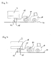
- Fig. 2 shows in an end view the parallel travel of the tractor 10 to the track 6, wherein the holding device 12 connects the tractor 10 with the trailer 2 for transmitting the tensile force.
- the trailer 2 rolls with its wheels 14 on the top or in the lanes of the wagon 4.
- the trailer 2 at its front end, the trailer 2 on a kingpin 16, which serves to couple the trailer 2 with a semi-trailer or a tractor.
- the kingpin 16 is gripped by a coupling 18 at one end of the arm of the holding device 12.
- the coupling 18 is preferably designed as an automatic or remote controlled locking and releasable coupling to couple the trailer 2 without further handling operations with the holding device 12 and decouple again.
- the holding device 12 is mounted on the tractor 10 via a lifting device 20.
- the lifting device 20 serves to be able to lift the entire holding device 12 with the coupling 18. This is firstly necessary in order to lift the front end of the trailer 2 for moving the trailer 2, so that the feet 22 (see FIGS. 3 and 4) on which the trailer 2 stands when it is not connected to a tractor or a semitrailer is coupled, can be lifted from the ground. This makes it possible to move the trailer 2 in a known manner without folding the support feet 22 previously.
- the lifting device 20 on the other serves to compensate for the height difference H between the road surface 24 on which the tractor 10 moves and the top of the railroad car 4 on which the wheels 14 of the trailer 2 roll.
- This compensation could be dispensed with if the road surface 24 is placed higher relative to the track 6, so that the surface of the carriage 4 and the road surface 24 lie in the same horizontal plane.
- the lifting device 20 is controlled so that it is continuously raised when moving the trailer 2 on the ramp 8, so that the distance of the trailer 2 in the region of its front end on the kingpin 16 to the road on which the trailer 2 with its wheels 14 moves, stays about the same.
- Fig. 2 it can also be seen that the tractor 10 is parallel to the track 6 and a wagon on it 4, laterally offset by the distance D moves.
- the distance D corresponds essentially to half the width of the wagon plus half the width of the tractor 10 plus the required distance between the tractor 10 and Waggon 4.
- the arm of the holding device 12 must be designed to be correspondingly long, ie it must have at least the length of the distance D, at an oblique extent, as shown in Fig. 1, the length must be equal to D / sin ⁇ , where Alpha the Inclination angle of the holding device 12 to the direction of travel F and the longitudinal axis X is.
- the holding device 12 can also be designed so that its length can be changed in order to be able to adapt the holding device 12 to different spatial conditions during its use.
- the holding device 12 is rotatably mounted on the kingpin 16 via the coupling 18 and mounted correspondingly rotatable on the lifting device 20. This makes it possible that the holding device 12 or the arm of the holding device 12 can pivot so that it extends parallel to the direction of travel F of the tractor 10, d. H. the angle ⁇ is zero. This is the case when a trailer 12 is to be moved normally on a road or a storage area and is not moved on a train.
- the holding device 12 is expediently in desired angular positions fixable or lockable. This is in particular the angular position in which the angle ⁇ is equal to zero and the deflected angular position shown in FIG. 1, in which the holding device 12 is located when the trailer 2 is moved on the wagon 4.
- Fig. 3 shows a side view of the tractor 10 with attached trailer 2, in which the trailer 2 is in the position behind the tractor 10, ie the trailer 2 is moved in the direction of travel F of the tractor 10 without parallel offset.
- FIG 4 shows a corresponding view of a second embodiment in which a support roller 26 is attached to the holding device 12 near the coupling 18.
- the support roller 26 serves to support the weight of the trailer 2 at its front end directly on the ground 24, so that the holding device 12 does not have to pick up this load and transfer it to the tractor 10. In this way, overturning of the tractor 10 can be prevented.
- the holding device 12 and the lifting device 20 can be dimensioned correspondingly lighter.
- the support roller 26 is configured to be preferably movable in the vertical direction so that when the trailer 2 is lifted above the lifting device 20, it can be held in contact with the ground 24 to lower the load of the trailer 2 to the ground transferred to. The support roller 26 rolls when moving the trailer 2 on the cars 4 on the top of the cars 4 and the lanes formed there from.
- the coupling 18 of the holding device 12 is released and the holding arm can then swung away in the direction of the angle a from the car, ie be moved out of the gauge 28 (see dashed line in Fig. 2).
- the tractor 10 can then move away from the wagon 4 and record, for example, a next trailer 2 for loading.
- the wagons 4 can move undisturbed by the holding device 12 on the track 6.
- the tractor is returned to the position shown in FIG. 1 and the holding device 12 pivoted back into the clearance 28 and the coupling 18 coupled to the kingpin 16 of the trailer 2.
- the trailer 2 can then be pulled down in the direction of the longitudinal axis X of the cars 4.
- the train 4 must be rotated by 180 ° to the ramp 8, so that the trailer 2 on the ramp 8 can be pulled down to the ground 24 again.
- the invention has been described using the example of a traction device in the form of a tractor 10 with a holding device 12 connected thereto.
- the holding device 12 may also be part of a permanently installed system.
- the traction device instead of a tractor 10 having a permanently installed Verfahrstrom, which can move parallel to the tracks 6. This can be designed for example in the form of a gantry crane or the like.
Abstract
Description
Die Erfindung betrifft ein Verfahren sowie eine Vorrichtung zum Laden von Trailern auf Eisenbahnwaggons.The invention relates to a method and a device for loading trailers on railway cars.
Es gibt seit längerem das Bestreben, den Güterverkehr verstärkt von der Straße auf die Eisenbahn zu verlagern. Dazu ist es bekannt, ganze LKW oder auch nur die Trailer, d. h. Sattelauflieger ohne Zugmaschine auf Eisenbahnwaggons zu verladen. Dies geschieht insbesondere in Häfen, wo die Trailer im RoRo-Verkehr mit Schiffen angelandet werden und dann zum Weitertransport auf Eisenbahnwaggons verladen werden sollen.There has been a long-standing desire to shift goods traffic from road to rail. For this it is known, whole trucks or just the trailer, d. H. Semi-trailer without tractor to load on railway wagons. This happens especially in harbors, where the trailers are landed in the RoRo traffic with ships and then to be loaded on railway wagons for further transport.
Zum Verladen der Trailer auf Eisenbahnwaggons sind so genannte kranbare Trailer bekannt, welche wie Container mittels eines Krans angehoben und auf die Eisenbahnwaggons gesetzt werden können. Dies bedeutet, dass zum Verladen spezielle Trailer erforderlich sind, d. h. nicht jeder Trailer mittels der vorhandenen Krananlagen auf Eisenbahnwaggons verladen werden kann. Dies ist ein großes Problem, da der größte Teil der im Einsatz befindlichen Trailer nicht kranbar ist.For loading the trailer on railway wagons so-called craneable trailers are known, which can be lifted like containers by means of a crane and placed on the railway wagons. This means that special trailers are required for loading, d. H. not every trailer can be loaded on railway wagons using the existing crane systems. This is a big problem as most of the trailers in use are not cranible.
Alternativ sind Eisenbahnwaggons entwickelt worden, welche es ermöglichen, die Trailer seitlich auf die Waggons zu rollen. Um diese Verladetechnik im großen Stil einzusetzen, ist es jedoch erforderlich, die bislang eingesetzten Waggons durch die neuartigen Waggons zu ersetzen, was große Investitionen erfordern würde und aus diesem Grund nicht möglich ist.Alternatively, railway wagons have been developed which allow the trailers to roll laterally onto the wagons. To use this loading technology on a large scale, however, it is necessary to replace the previously used wagons with the new wagons, which would require large investments and for this reason is not possible.
Es ist Aufgabe der Erfindung, ein verbessertes Verfahren zum Laden von Trailern auf Eisenbahnwaggons sowie eine zugehörige Vorrichtung zu schaffen, welche es ermöglichen, herkömmliche Trailer auf einfache Weise auf herkömmliche Eisenbahnwaggons zu verladen.It is an object of the invention to provide an improved method for loading trailers on railway wagons and an associated device, which make it possible to load conventional trailers in a simple manner on conventional railway cars.
Diese Aufgabe wird durch ein Verfahren mit den im Anspruch 1 angegebenen Merkmalen sowie durch eine Vorrichtung mit den im Anspruch 7 angegebenen Merkmalen gelöst.This object is achieved by a method having the features specified in claim 1 and by a device having the features specified in claim 7.
Gemäß dem erfindungsgemäßen Verfahren werden die Trailer zum Verladen der Eisenbahnwaggons von einem Längsende des Waggons her auf den Waggon bzw. Zug gerollt, wie es beispielsweise auch bei herkömmlichen Autoreisezügen geschieht. Dabei wird jedoch nur der Trailer, d. h. ohne Zugmaschine bzw. Sattelschlepper verladen. Um dies zu ermöglichen, wird bei dem erfindungsgemäßen Verfahren eine Zugeinrichtung eingesetzt, welche den Trailer auf den Eisenbahnwaggon zieht. Dabei ist erfindungsgemäß die Zugeinrichtung so ausgebildet, dass sie sich seitlich oder oberhalb des Lichtraumprofiles des Waggons, d. h. seitlich oder oberhalb des beladenen Eisenbahnwaggons parallel zu dessen Längsrichtung bewegt. D. h. die Zugeinrichtung bewegt sich nicht direkt auf dem Waggon selber, sondern außerhalb des Lichtraumprofiles des Waggons, d. h. der durch den beladenen Waggon eingenommenen Querschnittsfläche. Auf diese Weise ist es möglich, herkömmliche Trailer ohne ihre Zugmaschine bzw. einen Sattelschlepper auf herkömmliche Eisenbahnwaggons zu ziehen, wobei die Trailer in Fahrtrichtung der Eisenbahnwaggons, d. h. in Längsrichtung des Waggons bzw. des Zuges bewegt werden. Es sind weder spezielle Eisenbahnwaggons noch spezielle Trailer erforderlich, um die Trailer auf die Eisenbahnwaggons zu laden. Es muss lediglich an der Verladestelle eine entsprechend ausgebildete Zugeinrichtung vorgesehen sein bzw. vorhanden sein, um die Trailer verfahrensgemäß auf den Waggon zu ziehen.According to the method of the invention, the trailers are loaded for loading the railway wagons from a longitudinal end of the wagon on the wagon or train, as is done for example in conventional car trains. However, only the trailer, ie loaded without tractor or semitrailer. In order to make this possible, a towing device is used in the method according to the invention, which pulls the trailer on the railroad car. In this case, according to the invention, the traction device is designed such that it moves laterally or above the clearance gauge of the wagon, ie laterally or above the loaded railway wagon, parallel to its longitudinal direction. Ie. the towing device does not move directly on the wagon itself, but outside the clearance gauge of the wagon, ie the cross-sectional area occupied by the loaded wagon. In this way, it is possible to draw conventional trailers without their tractor or a semi-trailer on conventional railway cars, the trailer in the direction of travel of the railway wagons, ie in the longitudinal direction of the car or the train to be moved. Neither special railroad cars nor special trailers are required to load the trailers onto the railway wagons. It must be provided only at the loading point a suitably trained traction device be present in order to pull the trailer according to the method on the car.
Entsprechend können die Trailer von dem Waggon auch wieder abgeladen werden, indem die sich seitlich oder oberhalb des Waggons bewegende Zugeinrichtung den Trailer in Längsrichtung von dem Waggon herunterzieht bzw. rollt. Um die Trailer auf den Waggons greifen zu können, weist die Zugeinrichtung vorzugsweise ein Greifelement auf, welches sich in das Lichtraumprofil des beladenen Waggons hineinerstreckt. Die Lauffläche, auf welcher sich die Zugeinrichtung bewegt, ist jedoch auf jeden Fall außerhalb des Lichtraumprofiles des Waggons, d. h. beabstandet von dem Waggon angeordnet, so dass die Zugeinrichtung sich unabhängig von den Waggons bewegen kann.Correspondingly, the trailers can also be unloaded from the wagon by the traction device moving laterally or above the wagon pulling down the trailer in the longitudinal direction from the wagon. In order to be able to grip the trailers on the wagons, the pulling device preferably has a gripping element which extends into the gauge of the loaded wagon. However, the running surface on which the pulling device moves is in any case outside the gauge of the wagon, d. H. spaced from the car, so that the towing device can move independently of the cars.
Bevorzugt wird das erfindungsgemäße Verfahren so eingesetzt, dass ein gesamter Zug bestehend aus mehreren Waggons derart mit Trailern beladen wird, dass die Trailer jeweils von einem Längsende des Zuges, vorzugsweise alle vom selben Längsende her, auf diesen gerollt werden, wobei sie von einer sich auf einer separaten Lauffläche seitlich oder oberhalb des Lichtraumprofils des Zuges bewegenden Zugeinrichtung gezogen werden. Um die Trailer auf den Zug bzw. Waggon zu rollen, ist eine Rampe vorgesehen, welche sich an den letzten Waggon des Zuges anschließt, über welche die Trailer auf den Zug gerollt werden. Vorzugsweise endet das Gleis, auf dem der Zug steht, stirnseitig an einer entsprechenden Rampe, wie es von Verladestellen für Autos auf Autoreisezüge bekannt ist. Die Lauffläche ist zweckmäßig so ausgebildet, dass sie sich parallel zu dem Gleis über die gesamte Länge des Zuges erstreckt, so dass sich die Zugeinrichtung parallel zu dem Zug über dessen Gesamtlänge bewegen kann. So können die Trailer von einem Längsende her auf den Zug gezogen werden und der gesamte Zug auf diese Weise beladen werden. Besonders bevorzugt können mehr als eine Zugeinrichtung eingesetzt werden, um ein schnelles Beladen des Zuges zu ermöglichen. Auf diese Weise können mehre Trailer gleichzeitig hintereinander auf dem zu beladenen Zug bewegt werden.Preferably, the inventive method is used so that an entire train consisting of several wagons is loaded with trailers that the trailer are each rolled from one longitudinal end of the train, preferably all from the same longitudinal end ago, on them from one to a separate tread laterally or above the gauge of the train moving pulling device are pulled. To roll the trailers onto the train or wagon, a ramp is provided, which adjoins the last wagon of the train, over which the trailers are rolled onto the train. Preferably, the track on which the train is located terminates at the front of a corresponding ramp, as known from automobile loading points to car trains. The tread is expediently designed to extend parallel to the track over the entire length of the train, so that the towing device can move parallel to the train over its entire length. Thus, the trailer can be pulled from one longitudinal end on the train and the entire train to be loaded in this way. More preferably, more than one traction device can be used to facilitate rapid loading to allow the train. In this way, several trailers can be moved simultaneously one behind the other on the train to be loaded.
Weiter bevorzugt ist die Zugeinrichtung an einer Führungsbahn geführt, welche sich parallel zu dem Waggon oder zu einem aus mehreren Waggons bestehenden Zug erstreckt. Diese Führungsbahn stellt sicher, dass die Zugeinrichtung sich parallel zu den Waggons bewegt, so dass die von der Zugeinrichtung ergriffenen Trailer genau in Längsrichtung des Zuges bewegt werden können und nicht unbeabsichtigt seitlich vom Zug heruntergezogen werden. Die Führungsbahn kann auch am Waggon selber ausgebildet sein.Further preferably, the traction device is guided on a guideway which extends parallel to the wagon or to a train consisting of several wagons. This guideway ensures that the traction device moves parallel to the wagons, so that the trailers grabbed by the traction device can be moved exactly in the longitudinal direction of the train and are not unintentionally pulled down the side of the train. The guideway may also be formed on the wagon itself.
Die Zugeinrichtung ergreift die Trailer vorzugsweise an deren vorderen zur Aufnahme an einer Zugmaschine bestimmten Ende. D. h. besonders bevorzugt ergreift die Zugeinrichtung die Trailer an ihrem Königszapfen, mit welchem die Trailer sonst in die Kupplung an einem Sattelschlepper angreifen. D. h. beim Verladen wird die Zugkraft zur Bewegung der Trailer dort eingeleitet, wo die Trailer auch sonst im Straßenverkehr gezogen werden, so dass die Trailer nicht außergewöhnlich belastet werden. Dies ermöglicht den Einsatz herkömmlicher Trailer für die Verladung auf Eisenbahnwaggons. Ferner handelt es sich bei diesen Kupplungen, welche an den Trailern ausgebildet sind um standardisierte Kupplungen, so dass eine entsprechend ausgebildete Zugeinrichtung im Wesentlichen alle im Straßenverkehr im Einsatz befindlichen Trailer greifen und verladen kann.The traction device preferably grips the trailers at their front end for receiving at a tractor. Ie. particularly preferably, the drawbar grips the trailer with its kingpin, with which the trailer otherwise attack the coupling on a semi-trailer. Ie. when loading the traction is initiated to move the trailer where the trailers are pulled elsewhere in the road, so that the trailer will not be charged abnormally. This allows the use of conventional trailers for loading on railway wagons. Furthermore, these clutches, which are formed on the trailers to standardized clutches, so that a trained traction device can grip and load substantially all trailers in use in the road.
Beim Verladen kann die Zugeinrichtung ferner die Trailer vorzugsweise an ihrem vorderen Ende so weit anheben, dass die Standfüße, auf welchen die Trailer bei abgekuppelter Zugmaschine stehen, vom Boden abgehoben werden und die Trailer allein auf ihren Rädern gerollt werden können.When loading the drawbar may also raise the trailer preferably at its front end so far that the feet on which the trailer stand at uncoupled tractor are lifted off the ground and the trailer can be rolled alone on their wheels.
Weiter bevorzugt wird der den Trailer greifende Teil der Zugeinrichtung, nachdem der Trailer in die gewünschte Position auf dem Waggon oder Zug gezogen worden ist, von dem Waggon bzw. Zug bezüglich der Längsrichtung des Waggons zur Seite oder nach oben wegbewegt. Das bedeutet, der den Trailer greifende Teil der Zugeinrichtung greift während des Verladevorganges in das Lichtraumprofil bzw. die Lichtraumbegrenzung des Zuges ein, so dass die Kupplung, welcher die Trailer greift, vorzugsweise in etwa in der Mitte der Waggonbreite angeordnet ist, um den Trailer in Längsrichtung auf dem Waggon bewegen zu können. Die Bewegungsbahn der Zugeinrichtung, bzw. die Lauffläche der Zugeinrichtung, auf welcher sich diese bewegt, befindet sich jedoch außerhalb des Lichtraumprofiles des Zuges. Der in das Lichtraumprofil eingreifende Teil der Zugeinrichtung, welcher die Trailer ergreift, wird nach dem Verladevorgang des Trailers aus dem Lichtraumprofil herausbewegt bzw. geschwenkt, so dass die Zugeinrichtung sich dann ohne den Trailer außerhalb des Lichtraumprofiles bewegen kann, um einen nächsten Trailer zu ergreifen und zu verladen. Ferner kann sich der vollständig beladene Zug relativ zu der Zugeinrichtung bewegen, ohne dass diese die Bewegung des Zuges behindert. Zum Entladen der Trailer von den Eisenbahnwaggons wird der Teil der Zugeinrichtung, welcher den Trailer ergreifen soll, zunächst von der Seite oder von oben her über den Waggon bewegt, um den Trailer an seinem vorderen Ende zu ergreifen. Anschließend wird der Trailer durch Bewegung der Zugeinrichtung von dem Waggon bzw. Zug gezogen.More preferably, after the trailer has been pulled into the desired position on the wagon or train, the part of the traction device that engages the trailer is moved away from the wagon with respect to the longitudinal direction of the wagon to the side or upwards. This means that the trailer engaging part of the pulling device engages during the loading process in the clearance space or the light space limit of the train, so that the clutch which engages the trailer, preferably located approximately in the middle of the wagon width to the trailer in To be able to move longitudinally on the wagon. However, the trajectory of the traction device, or the running surface of the traction device on which it moves, is located outside the gauge of the train. The engaging in the clearance profile of the pulling device which grabs the trailer is moved out of the gauge space after the loading process of the trailer or swung so that the traction device can then move without the trailer outside of the clearance space to take a next trailer and to load. Further, the fully loaded train may move relative to the towing means without obstructing the movement of the train. To unload the trailers from the railway wagons, the part of the towing device which is to grip the trailer is first moved from the side or from above over the wagon in order to grip the trailer at its front end. Subsequently, the trailer is pulled by movement of the traction device of the car or train.
Besonders bevorzugt wird das erfindungsgemäße Verfahren in der Weise ausgeführt, dass als Zugeinrichtung eine Zugmaschine Verwendung findet, welche seitlich des Waggons oder des Zuges parallel versetzt zu diesem fährt. D. h. die Zugmaschine fährt seitlich des Zuges parallel versetzt zu dem sich auf dem Zug bzw. Waggon bewegenden Trailer, wobei Zugmaschine und Trailer über ein Element der Zugeinrichtung z. B. einen Haltearm miteinander verbunden sind. Solche Zugmaschinen sind unter der Bezeichnung "Tugmaster" bekannt und werden beispielsweise in Häfen eingesetzt, um dort die Trailer, welche ohne Sattelschlepper auf Schiffe verladen werden, zu bewegen. Erfindungsgemäß ist es besonders bevorzugt, dass eine solche Zugmaschine so ausgestaltet ist, dass sie als Zugeinrichtung zum Verladen der Trailer auf die Eisenbahnwaggons dienen kann. Dies ermöglicht es beispielsweise, dass mittels der Zugmaschinen die Trailer von einem Schiff gezogen werden und dann direkt gemäß dem erfindungsgemäßen Verfahren auf Eisenbahnzüge verladen werden können, ohne dass die Trailer noch von anderen Handhabungseinrichtungen ergriffen werden können. Dies ermöglicht ein sehr schnelles und effektives Verladen der Trailer, ohne dass spezielle Trailer oder Eisenbahnzüge zum Einsatz kommen müssten.Particularly preferably, the inventive method is carried out in such a way that as a traction device, a tractor is used, which moves laterally offset parallel to the wagon or the train to this. Ie. the tractor moves laterally offset from the train parallel to the moving on the train or wagon trailer, said tractor and trailer via an element of the draw gear z. B. a holding arm are connected together. Such tractors are known under the name "Tugmaster" and are used, for example, in ports to move there, the trailer, which are loaded without semi-trailer on ships. According to the invention it is particularly preferred that such a tractor is designed so that it can serve as a drawbar for loading the trailer on the railway cars. This makes it possible, for example, that by means of the tractors the trailers are pulled from a ship and then directly loaded according to the method of the invention on trains without the trailer can be taken by other handling devices. This allows a very fast and effective loading of the trailer without the need for special trailers or trains.
Alternativ kann die Zugeinrichtung als stationäre Anlage an dem Gleis, an welchem die Trailer auf Eisenbahnwaggons verladen werden, angeordnet sein und sich z. B. auf einer parallel zu dem Gleis erstreckenden Schiene bewegen.Alternatively, the traction device can be arranged as a stationary system on the track to which the trailers are loaded on railway wagons, and z. B. move on a parallel to the track extending rail.
Die Erfindung betrifft ferner eine Vorrichtung zum Laden von Trailern auf Eisenbahnwaggons, mit welcher das zuvor beschriebene Verfahren ausgeführt werden kann. Die Vorrichtung weist eine Zugeinrichtung auf, welche seitlich oder oberhalb eines Gleises außerhalb des Lichtraumprofiles des beladenen Waggons parallel zu dem Gleis bewegbar ist, ohne mit den Eisenbahnwaggons oder den auf diesen angeordneten Trailern zu kollidieren. An der Zugeinrichtung ist eine Halteeinrichtung mit einer Kupplung zum lösbaren Ankuppeln an einen Trailer angebracht. Mit dieser Kupplung können die Trailer gegriffen werden, um durch die sich bewegende Zugeinrichtung bewegt bzw. gerollt zu werden. Die Halteeinrichtung ist dabei so ausgebildet, dass mittels der Kupplung Trailer ergriffen werden können, wenn sie auf einem auf dem Gleis stehenden Waggon angeordnet sind, während die Zugeinrichtung, d. h. insbesondere deren Verfahr- bzw. Antriebseinheit außerhalb des Lichtraumprofiles des Zuges angeordnet ist. D. h. die Halteeinrichtung greift von außen in das Lichtraumprofil des Zuges ein, um dort die Trailer zu ergreifen. Die Bewegung der Zugeinrichtung wird jedoch außerhalb des Lichtraumprofiles des Zuges bzw. der Waggons erzeugt. D. h. insbesondere dass die Zugeinrichtung nicht angetrieben auf den Waggons selber abrollt. So bewegt sich die Zugeinrichtung nicht vor dem zu ziehenden Trailer, sondern parallel versetzt zu diesem auf einer getrennten Fahrspur.The invention further relates to a device for loading trailers on railway wagons, with which the method described above can be carried out. The device comprises a traction device which is movable laterally or above a track outside the gauge of the loaded wagon parallel to the track without colliding with the railway wagons or the trailers arranged thereon. At the traction device, a holding device with a coupling for detachable coupling is attached to a trailer. With this clutch, the trailers can be gripped to be rolled by the moving towing device. The holding device is designed so that by means of the coupling trailer can be taken if they are arranged on a wagon standing on the track, while the traction device, ie in particular their Verfahr- or drive unit outside the gauge of the train is arranged. Ie. the holding device engages from the outside in the clearance profile of the train to take the trailer there. However, the movement of the traction device is generated outside the gauge of the train or wagons. Ie. in particular that the traction device does not roll on the wagons itself driven. Thus, the towing device does not move in front of the trailer to be pulled, but offset parallel to this on a separate lane.
Die Zugeinrichtung ist so ausgebildet, dass sie sich auf einer Laufbahn bzw. Lauffläche, welche sich parallel zu dem Gleis erstreckt, fährt bzw. abrollt. Lediglich ein Teil der Zugeinrichtung greift in den Bereich oberhalb der Eisenbahnwaggons ein, um dort Trailer zu bewegen und in Längsrichtung über die Waggons zum Be- und Entladen der Waggons zu ziehen.The pulling device is designed such that it moves or rolls on a track or running surface which extends parallel to the track. Only a part of the traction device engages in the area above the railway wagons in order to move there trailers and to pull in the longitudinal direction of the wagons for loading and unloading the wagons.
Vorzugsweise ist die Halteeinrichtung so ausgebildet, dass sie quer zur Erstreckungsrichtung des Gleises in das Lichtraumprofil hinein und aus diesem heraus bewegbar ist. Dies ermöglicht es, dass wenn die Trailer hintereinander auf einem Eisenbahnwaggon stehen, so dass wenig Freiraum zwischen den hintereinander stehenden Trailern verbleibt, die Halteeinrichtung zwischen den einzelnen Trailern von dem Waggon wegbewegt oder zu diesem hinbewegt werden kann. Zum Beladen des Zuges werden die Trailer mittels der Halteeinrichtung in Längsrichtung auf den Zug bzw. dessen Waggons gezogen. Wenn die Trailer die gewünschte Position erreicht haben, wird die Kupplung der Halteeinrichtung gelöst und die Halteeinrichtung dann nach oben oder seitlich, d. h. quer zur Bewegungsrichtung der Trailer, insbesondere normal zur Bewegungsrichtung der Trailer aus dem Lichtraumprofil des Zuges heraus bewegt. Dies kann durch eine lineare oder Schwenkbewegung geschehen. Dazu kann die Halteeinrichtung an der Zugeinrichtung verschwenkbar sein. Ferner kann die Halteeinrichtung auch teleskopierbar ausgebildet sein, um aus dem Lichtraumprofil des Waggons herausbewegt werden zu können. Alternativ ist es möglich, die gesamte Zugeinrichtung mit dem Haltearm quer zu der Längsrichtung bzw. Bewegungsrichtung der Trailer und der Waggons zu bewegen.Preferably, the holding device is designed so that it is movable transversely to the direction of extension of the track in the clearance profile and out of this. This makes it possible that when the trailers are behind each other on a railroad car, so that little space between the successive trailers remains, the holding device between the individual trailers can be moved away from the wagon or moved to this. To load the train, the trailers are pulled by means of the holding device in the longitudinal direction of the train or its wagons. When the trailer has reached the desired position, the coupling of the holding device is released and the holding device then up or laterally, ie transversely to the direction of movement of the trailer, in particular moves normal to the direction of movement of the trailer from the gauge of the train out. This can be done by a linear or pivoting movement. For this purpose, the holding device can be pivotable on the pulling device. Furthermore, the holding device can also be telescoped be designed to be moved out of the gauge of the car can. Alternatively, it is possible to move the entire pulling device with the holding arm transversely to the longitudinal direction or movement direction of the trailer and the wagons.
Die Halteeinrichtung weist vorzugsweise eine Kupplung korrespondierend zu einem Königszapfen von Trailern auf. Dies ermöglicht es nahezu alle gängigen Trailer, welche mit solchen Königszapfen zur Ankupplung an Sattelschlepper versehen sind, zu ergreifen und mit der erfindungsgemäßen Vorrichtung auf Eisenbahnwaggons zu verladen bzw. von Eisenbahnwaggons abzuladen.The holding device preferably has a coupling corresponding to a kingpin of trailers. This makes it possible to take almost all popular trailers, which are provided with such kingpin for coupling to semi-trailer, and loaded with the inventive device on railway cars or unloading of railway cars.
Weiter bevorzugt ist die Kupplung als automatische Kupplung ausgebildet, d. h. dass die Kupplung ferngesteuert von einer Bedienperson der Zugeinrichtung oder auch vollautomatisch geöffnet und geschlossen werden kann, um die Halteeinrichtung von dem Trailer ab- und anzukuppeln.More preferably, the clutch is designed as an automatic clutch, d. H. in that the coupling can be remotely opened and closed automatically by an operator of the towing device or also in order to disconnect and couple the holding device from the trailer.
Gemäß einer weiteren bevorzugten Ausführungsform ist in der Nähe der Kupplung an der Halteeinrichtung eine auf dem Boden abrollende Tragrolle angeordnet. Auf diese Weise kann das Gewicht des Trailers an dessen vorderen Ende, wo üblicherweise keine Achsen angeordnet sind, direkt auf den Boden übertragen werden, um die Belastung der Halteeinrichtung und die Momentenbelastung auf die Zugeinrichtung zu minimieren. Beim Verladen läuft die Tragrolle dann auf der Lauffläche an der Oberseite der Eisenbahnwaggons. Nachdem die Trailer in ihre entsprechende Position bewegt sind, wird die Tragrolle gemeinsam mit der Halteeinrichtung quer zur Bewegungsrichtung der Trailer aus dem Lichtraumprofil des Zuges bzw. Waggons heraus bewegt. Dazu kann die Tragrolle so ausgebildet sein, dass sie angehoben werden kann, um von der Oberseite des Eisenbahnwaggons außer Kontakt gebracht zu werden und beispielsweise über den seitlichen Rand des Eisenbahnwaggons hinweg bewegt zu werden.According to a further preferred embodiment, a carrying roller rolling on the ground is arranged in the vicinity of the coupling on the holding device. In this way, the weight of the trailer at the front end, where usually no axles are arranged, can be transmitted directly to the ground, in order to minimize the load on the holding device and the moment load on the pulling device. When loading the idler then runs on the tread at the top of the railway cars. After the trailers are moved to their appropriate position, the support roller is moved together with the holding device transversely to the direction of movement of the trailer from the gauge of the train or wagon out. For this purpose, the support roller may be designed so that it can be lifted to be brought out of contact from the top of the railway car to be moved and, for example, over the side edge of the railroad car.
Besonders bevorzugt ist die Zugeinrichtung von einer Zugmaschine für Trailer gebildet, an welcher die Halteeinrichtung als schwenkbarer Arm ausgebildet ist, welcher mit seinem ersten Ende drehbar an der Zugmaschine befestigt ist und an dessen zweiten Ende die Kupplung angeordnet ist. Derartige Zugmaschinen sind unter der Bezeichnung "Tugmaster" bekannt und werden, wie oben ausgeführt, zum Bewegen der Trailer beispielsweise auf Hafengeländen verwendet. Die Halteeinrichtung kann als Zusatzteil ausgebildet sein, welches an herkömmlichen Zugmaschinen montiert werden kann. Die Halteeinrichtung ist an der Zugmaschine derart schwenkbar ausgebildet, dass bei normaler Bewegung der Trailer auf der Straße bzw. einem Stellplatz die Trailer in Fahrtrichtung hinter der Zugmaschine gezogen werden. Wenn die Trailer dann auf die Waggons gerollt werden sollen, wird der Haltearm so verschwenkt, dass er sich quer oder vorzugsweise zu einem Winkel von etwa 45° zur Fahrtrichtung der Zugmaschine und zur Fahrtrichtung des Trailers erstreckt. Dabei dreht sich der Haltearm sowohl an dem Trailer als auch an der Kupplung, welche ihn an dem Trailer festhält, so dass der Trailer dann seitlich versetzt zu der Zugmaschine steht und bei Fahrt der Zugmaschine parallel zu dieser bewegt wird. Auf diese Weise kann der Trailer dann auf den Eisenbahnwaggon gezogen werden und in Längsrichtung über den Zug bewegt werden, während sich die Zugmaschine seitlich des Zuges parallel zu diesem bewegt. D. h. Trailer und Zugmaschine bewegen sich in getrennten, zueinander parallelen Fahrspuren.Particularly preferably, the traction device is formed by a tractor for trailers, on which the holding device is designed as a pivotable arm, which is rotatably attached with its first end to the tractor and at the second end of the clutch is arranged. Such tractors are known under the name "Tugmaster" and are, as stated above, used to move the trailer, for example, on harbor grounds. The holding device can be designed as an additional part, which can be mounted on conventional tractors. The holding device is designed so pivotable on the tractor that during normal movement of the trailer on the street or a parking space, the trailer are pulled in the direction of travel behind the tractor. When the trailers are then to be rolled onto the carriages, the support arm is pivoted so that it extends transversely or preferably to an angle of about 45 ° to the direction of travel of the tractor and to the direction of travel of the trailer. In this case, the support arm rotates both on the trailer and on the clutch, which holds him to the trailer, so that the trailer is then offset laterally to the tractor and is moved parallel to this when driving the tractor. In this way, the trailer can then be pulled onto the railroad car and moved longitudinally over the train while the tractor moves laterally of the train parallel to it. Ie. Trailer and tractor move in separate, parallel lanes.
Vorzugsweise ist der Arm in einer horizontalen Ebene relativ zu der Zugmaschine und der Kupplung oder einem angekuppelten Trailer bewegbar, um diesen zuvor beschriebenen Versatz zwischen Trailer und Zugmaschine zum Be- und Entladen der Eisenbahnwaggons zu erreichen. Vorzugsweise dreht sich der Haltearm direkt in der Kupplung um den Königszapfen des Trailers.Preferably, the arm is movable in a horizontal plane relative to the tractor and the clutch or a trailer coupled to achieve this previously described offset between the trailer and tractor for loading and unloading the railway wagons. Preferably, the support arm rotates directly in the clutch to the kingpin of the trailer.
Weiter bevorzugt ist eine Hubeinrichtung vorgesehen, mittels welcher der Arm oder die Kupplung bezüglich der Zugmaschine vertikal bewegbar ist. Diese Hubeinrichtung ermöglicht es, die Trailer anzuheben, um die Standfüße des Trailers am vorderen Ende des Trailers vom Boden abzuheben, ohne die Standfüße einklappen zu müssen. Ferner wird es zum Verladen der Trailer auf die Eisenbahnwaggons üblicherweise so sein, dass die Trailer eine Rampe hinaufbewegt werden, da die Oberfläche der Eisenbahnwaggons üblicherweise höher als das Niveau der Straße bzw. des Platzes, auf dem die Trailer zugeführt werden, gelegen ist. Da die Zugmaschine sich erfindungsgemäß aber auf dieser Straßenfläche bzw. parallel zu diesem Platz bewegt, kommt es zu einem vertikalen Versatz zwischen Trailer und Zugmaschine beim Beladen, welcher durch die Hubeinrichtung ausgeglichen wird.More preferably, a lifting device is provided, by means of which the arm or the coupling with respect to the tractor is vertically movable. This lifting device makes it possible to lift the trailer to lift the feet of the trailer at the front end of the trailer from the ground without having to fold the feet. Further, for loading the trailers onto the railway wagons, it will usually be so that the trailers are moved up a ramp, as the surface of the railway wagons is usually located higher than the level of the road or the place where the trailers are fed. Since the tractor moves according to the invention but on this road surface or parallel to this place, there is a vertical offset between the trailer and tractor during loading, which is compensated by the lifting device.
Weiter bevorzugt ist der Halteeinrichtung bildende Arm in zumindest einer Winkelposition an der Zugmaschine arretierbar. Dies ist vorzugsweise die Winkelposition, in welcher der Trailer parallel zur Zugmaschine bewegt wird, d. h. insbesondere die Winkelposition, in welcher sich der Arm in der horizontalen Ebene in etwa 45° zur Fahrtrichtung der Zugmaschine erstreckt. Weiter bevorzugt ist der Arm auch noch in einer zweiten Position, in welcher er sich im Wesentlichen in Fahrtrichtung der Zugmaschine erstreckt, arretierbar oder in seinem Schwenkwinkel begrenzbar, so dass der Trailer hinter der Zugmaschine gezogen werden kann.More preferably, the holding device forming arm can be locked in at least one angular position on the tractor. This is preferably the angular position in which the trailer is moved parallel to the tractor, d. H. in particular the angular position in which the arm extends in the horizontal plane at approximately 45 ° to the direction of travel of the tractor. More preferably, the arm is still in a second position in which it extends substantially in the direction of travel of the tractor, lockable or limited in its swing angle, so that the trailer can be pulled behind the tractor.
Der Arm, welcher die Halteeinrichtung bildet, weist zweckmäßigerweise eine Länge auf, welche größer als die halbe Breite des Lichtraumprofiles zuzüglich der halben Breite der Zugmaschine ist. In der Praxis wird die Länge noch um den Abstand länger sein, in welchem sich die Zugmaschine parallel zu dem Eisenbahnwaggon bewegt, wenn der Arm sich beim Ziehen der Trailer in einem Winkel von 45° erstrecken soll, muss die Länge nochmals um den Faktor √2 größer sein. Durch diese Länge des Armes wird erreicht, dass die Trailer in der Fahrzeugmitte an ihrem Königszapfen ergriffen werden können und in Längsrichtung der Waggons bewegt werden können, während die Zugmaschine seitlich des Zuges parallel zu diesem fährt. Gemäß einer bevorzugten Ausführungsform kann der Arm der Halteeinrichtung teleskopierbar ausgebildet sein. Dies ermöglicht es, dass der Arm im ausgeschwenkten Zustand, wenn der Trailer parallel versetzt zu der Zugmaschine bewegt wird, eine größere Länge hat als in dem Zustand, in welcher der Trailer direkt hinter der Zugmaschine in derselben Fahrspur gezogen wird. Auf diese Weise ist es möglich, die Länge des Gespanns aus Zugmaschine und Trailer beim normalen Ziehen des Trailers zu verkürzen und die größere Länge der Halteeinrichtung nur für den Fahrzustand zu ermöglichen, in welchem der Trailer parallel zur Fahrspur der Zugmaschine bewegt werden soll, um auf den Eisenbahnwaggon verladen bzw. von dem Eisenbahnwaggon entladen zu werden.The arm which forms the holding device expediently has a length which is greater than half the width of the clearance space plus half the width of the tractor. In practice, the length will still be longer by the distance in which the tractor moved parallel to the rail car, if the arm is to extend at an angle of 45 ° when pulling the trailer, the length must be again larger by a factor of √2. This length of the arm is achieved that the trailer can be taken in the vehicle center at its kingpin and can be moved in the longitudinal direction of the wagons, while the tractor moves side of the train parallel to this. According to a preferred embodiment, the arm of the holding device can be designed to be telescopic. This allows the arm in the swung-out state, when the trailer is moved parallel offset to the tractor, has a greater length than in the state in which the trailer is pulled directly behind the tractor in the same lane. In this way, it is possible to shorten the length of the tractor and trailer team during normal pulling of the trailer and to allow the greater length of the holding device only for the driving condition in which the trailer is to be moved parallel to the lane of the tractor to to be loaded onto the railroad car or unloaded from the railroad car.
Weiter bevorzugt weist die Zugmaschine eine Führungseinrichtung auf, mittels welcher die Zugmaschine bei ihrer Fahrt parallel zu dem Gleis führbar ist. Durch diese Führungseinrichtung wird sichergestellt, dass der Trailer wirklich in Längsrichtung des Zuges bewegt wird und nicht unerwünschterweise seitlich vom Zug heruntergezogen wird. Die Führungseinrichtung kann regelungs- bzw. steuerungstechnisch realisiert werden, wobei eine Steuerung vorgesehen ist, welche durch entsprechende Positionserfassung sicherstellt, dass sich die Zugmaschine tatsächlich parallel zum Zug bewegt. Dies kann beispielsweise durch GPS-Signale oder Abstandsmessung zu dem Zug oder eine elektronische Führungseinrichtung z. B. im Boden, auf welchen die Zugmaschine fährt, realisiert werden. Alternativ ist es möglich, eine Führungsschiene bzw. Führungsspur vorzusehen, auf welcher eine Führungsrolle bzw. ein Führungsrad läuft. Insbesondere ist es möglich, dass ein Führungsrad auf der Fahrspur an der Oberseite des Eisenbahnwaggons läuft, in welcher sich auch die Räder des Trailers bewegen. Dies kann gleichzeitig die oben beschriebene Tragrolle sein.More preferably, the tractor on a guide device by means of which the tractor is feasible while driving parallel to the track. By this guide device ensures that the trailer is really moved in the longitudinal direction of the train and is not undesirably pulled down the side of the train. The guide device can be realized in terms of regulation or control, wherein a control is provided which ensures by corresponding position detection that the tractor actually moves parallel to the train. This can be done for example by GPS signals or distance measurement to the train or an electronic guide device z. B. in the ground on which the tractor is running, be realized. Alternatively, it is possible to provide a guide rail or guide track on which a guide roller or a guide wheel running. In particular, it is possible for a guide wheel to run in the lane at the top of the railroad car, in which the wheels of the trailer also move. This can simultaneously be the carrying roller described above.
Nachfolgend wird die Erfindung beispielhaft anhand der beigefügten Figuren beschrieben. In diesen zeigt:
- Fig. 1
- eine Draufsicht auf einen Zug beim Beladen mit einem Trailer,
- Fig. 2
- eine schematische Ansicht des Zuges beim Beladen mit einem Trailer von der Stirnseite aus gesehen,
- Fig. 3
- eine schematische Seitenansicht einer Zugmaschine mit einem angehängten Trailer und
- Fig. 4
- eine schematische Seitenansicht einer Zugmaschine mit einem angehängten Trailer gemäß einer zweiten Ausführungsform der Erfindung.
- Fig. 1
- a top view of a train when loading with a trailer,
- Fig. 2
- a schematic view of the train when loading with a trailer seen from the front,
- Fig. 3
- a schematic side view of a tractor with an attached trailer and
- Fig. 4
- a schematic side view of a tractor with an attached trailer according to a second embodiment of the invention.
Fig. 1 zeigt schematisch in einer Draufsicht den Verladevorgang eines Trailers 2 auf einen Zug bestehend aus mehreren Eisenbahnwaggons bzw. Waggons 4, von denen in Fig. 1 lediglich zwei vollständig gezeigt sind. Der Zug bestehend aus den Waggons 4 steht auf einem Gleis 6, welches stirnseitig an einer Rampe 8 endet, über welche die Trailer 2 auf die Waggons 4 gerollt werden können. Die Waggons 4 sind an ihren Übergängen so ausgestaltet, dass die Trailer 2 über die gesamte Länge des Zuges, d. h. von Waggon zu Waggon gerollt werden können. An den Waggonübergängen sind entsprechende Rampen bzw. Brücken vorgesehen, welche die Spalte zwischen den Waggons 4 beim Beladen überbrücken.Fig. 1 shows schematically in a plan view the loading operation of a
Erfindungsgemäß wird ein Trailer 2 beim Aufladen auf die Waggons 4 von einer Zugmaschine 10 über die Rampe 8 auf die Waggons 4 gezogen, wobei der Trailer 2 auf seinen Rädern rollt. Die Zugmaschine 10 ist eine übliche Zugmaschine bzw. ein üblicher Schlepper, wie er beispielsweise in Hafenanlagen zum Verladen von Trailern auf RoRo-Schiffe verwendet wird. Solche Zugmaschinen 10 sind beispielsweise unter der Bezeichnung "Tugmaster" bekannt.According to the invention, a
Um die Trailer 2 mittels der Zugmaschine 10 auf die Waggons 4 bewegen zu können, ist die Zugmaschine 10 mit einer speziellen Aufnahme bzw. Halteeinrichtung 12 versehen. Die Halteeinrichtung 12 ist als Arm ausgebildet, welcher an einem Ende schwenkbar an der Zugmaschine 10 gelagert ist und an seinem entgegengesetzten Ende eine Kupplung zum Ankuppeln an den Königszapfen des Trailers 2 aufweist. Der Arm der Halteeinrichtung 12 ist so lang ausgebildet, dass sich die Zugmaschine 10 beabstandet um das Maß D von der Mittelachse X des Gleises 6 in der Richtung F parallel zu dem Gleis 6 bewegen kann. Der Abstand D stellt dabei den Abstand zwischen der Mittelachse in Fahrtrichtung F der Zugmaschine 10 und der Längs- bzw. Mittelachse X des Gleises 6 dar. Die Halteeinrichtung 12 ist so gestaltet, dass sie sich vorzugsweise in einem Winkel α≤90° zu der Fahrtrichtung F, besonders bevorzugt im Winkel von 45° erstreckt, um eine optimale Zugkraftübertragung von der Zugmaschine 10 auf den Trailer 2 trotz des Versatzes der Fahrtrichtung F zur Längsachse X des Gleises 6 zu gewährleisten. Bei einem Winkel α = 45° muss der Arm somit eine Länge von mindestens √2 D haben.In order to move the
Es ist zu erkennen, dass zur Durchführung des erfindungsgemäßen Lade- bzw. Entladeverfahrens lediglich eine speziell ausgebildete Zugmaschine 10 erforderlich ist. Gegebenenfalls können hier herkömmliche Zugmaschinen 10 mit der Halteeinrichtung 12 versehen oder auch nachgerüstet werden. Im Übrigen sind weder spezielle Eisenbahnwaggons 4 noch Trailer 2 erforderlich. Erfindungsgemäß werden die Trailer von den Zugmaschinen 10 nicht nur auf dem Abstellgelände bzw. der Straßenfläche bewegt, wie es heutzutage beispielsweise beim Ent- und Beladen von Schiffen im RoRo-Verkehr geschieht, sondern können auch direkt auf die Waggons 4 geladen werden.It can be seen that only a specially designed
Dazu wird der Trailer 2 von der Zugmaschine 10 auf die Rampe 8 bewegt, wobei der Arm der Halteeinrichtung 12 in seine in Fig. 1 gezeigte Winkellage verschwenkt, so dass die Zugmaschine 10 sich parallel zu dem Gleis 6 bzw. den Waggons 4 seitlich versetzt bewegt und dabei den Trailer 2 weiter zieht, wobei dieser sich auf den Waggons 4 bewegt. Zugmaschine 10 und Trailer 2 bewegen dabei in parallelen getrennten Fahrspuren. Die parallele Bewegung der Zugmaschine 10 kann manuell durch den Fahrer gesteuert werden. Alternativ ist es auch möglich, hier eine Führungseinrichtung beispielsweise in Form einer speziellen Führung für die Zugmaschine oder durch elektronische Spurführung zu gewährleisten. Weiter bevorzugt ist es auch möglich, die Halteeinrichtung 12 an der Oberseite der Waggons in der Fahrspur für die Trailer 2 zu führen, um zu verhindern, dass die Zugmaschine 10 die Trailer 2 seitlich, d. h. quer zur Längsachse X von den Waggons 4 zieht.For this purpose, the
Fig. 2 zeigt in einer Stirnansicht die parallele Fahrt der Zugmaschine 10 zu dem Gleis 6, wobei die Halteeinrichtung 12 die Zugmaschine 10 mit dem Trailer 2 zur Übertragung der Zugkraft verbindet. Der Trailer 2 rollt mit seinen Rädern 14 auf der Oberseite bzw. in den Fahrspuren des Waggons 4. An seinem vorderen Ende weist der Trailer 2 einen Königszapfen 16 auf, welcher dazu dient, den Trailer 2 mit einem Sattelschlepper bzw. einer Zugmaschine zu kuppeln. Der Königszapfen 16 wird durch eine Kupplung 18 an einem Ende des Armes der Halteeinrichtung 12 gegriffen. Über diese Kupplung 18 wird die Zugkraft von der Halteeinrichtung 12 auf den Trailer 2 übertragen. Die Kupplung 18 ist vorzugsweise als automatisch bzw. ferngesteuert schließ- und lösbare Kupplung ausgebildet, um die Trailer 2 ohne weitere Handhabungsvorgänge mit der Halteeinrichtung 12 kuppeln und wieder entkuppeln zu können.Fig. 2 shows in an end view the parallel travel of the
Die Halteeinrichtung 12 ist über eine Hubeinrichtung 20 an der Zugmaschine 10 angebracht. Die Hubeinrichtung 20 dient dazu, die gesamte Halteeinrichtung 12 mit der Kupplung 18 anheben zu können. Dies ist zum einen erforderlich, um das vordere Ende des Trailers 2 zum Bewegen des Trailers 2 anzuheben, so dass die Standfüße 22 (siehe Fig. 3 und 4), auf welchen der Trailer 2 steht, wenn er nicht an eine Zugmaschine oder einen Sattelschlepper angekuppelt ist, vom Boden angehoben werden können. Dies ermöglicht, den Trailer 2 in bekannter Weise ohne vorheriges Einklappen der Stützfüße 22 zu bewegen. Erfindungsgemäß dient die Hubeinrichtung 20 zum anderen dazu, den Höhenunterschied H zwischen der Straßenfläche 24, auf welcher sich die Zugmaschine 10, bewegt sowie der Oberseite des Eisenbahnwaggons 4, auf welcher die Räder 14 des Trailers 2 rollen, auszugleichen. Auf diesen Ausgleich könnte verzichtet werden, wenn die Straßenfläche 24 relativ zu dem Gleis 6 höher gelegen angeordnet wird, so dass die Oberfläche des Waggons 4 und die Straßenfläche 24 in derselben horizontalen Ebene liegen. Die Hubeinrichtung 20 wird so gesteuert, dass sie beim Hinaufbewegen des Trailers 2 auf die Rampe 8 kontinuierlich angehoben wird, so dass der Abstand des Trailers 2 im Bereich seines vorderen Endes am Königszapfen 16 zu der Fahrbahn, auf welcher sich der Trailer 2 mit seinen Rädern 14 bewegt, etwa gleich bleibt.The holding
In Fig. 2 ist ferner zu erkennen, dass die Zugmaschine 10 sich parallel zu dem Gleis 6 und einen darauf stehenden Waggon 4, seitlich versetzt um den Abstand D, bewegt. Dabei entspricht der Abstand D im Wesentlichen der halben Waggonbreite plus der halben Breite der Zugmaschine 10 zuzüglich des erforderlichen Abstandes zwischen Zugmaschine 10 und Waggon 4. Der Arm der Halteeinrichtung 12 muss entsprechend lang ausgebildet sein, d. h. er muss mindestens die Länge des Abstandes D haben, bei schräger Erstreckung, wie in Fig. 1 gezeigt, muss die Länge gleich D/sin α sein, wobei Alpha der Neigungswinkel der Halteeinrichtung 12 zu der Fahrtrichtung F bzw. der Längsachse X ist. Die Halteeinrichtung 12 kann auch so ausgebildet sein, dass ihre Länge verändert werden kann, um die Halteeinrichtung 12 an verschiedene räumliche Gegebenheiten bei ihrem Einsatz anpassen zu können.In Fig. 2 it can also be seen that the
Die Halteeinrichtung 12 ist über die Kupplung 18 an dem Königszapfen 16 drehbar gelagert und entsprechend drehbar an der Hubeinrichtung 20 angebracht. Dies ermöglicht es, dass die Halteeinrichtung 12 bzw. der Arm der Halteeinrichtung 12 so verschwenken kann, dass er sich parallel zu der Fahrtrichtung F der Zugmaschine 10 erstreckt, d. h. der Winkel α gleich Null ist. Dies ist der Fall, wenn ein Trailer 12 normal auf einer Straße oder einer Abstellfläche bewegt werden soll und nicht auf einem Zug verfahren wird. Um stets eine präzise Führung des Trailers 2 sowohl in der in Fig. 1 gezeigten Position als auch in der Position, in welche er sich hinter der Zugmaschine 10 in Richtung der Fahrtrichtung F bewegt, sicherstellen zu können, ist die Halteeinrichtung 12 zweckmäßigerweise in gewünschten Winkelpositionen fixier- bzw. arretierbar. Dies ist insbesondere die Winkellage, in welcher der Winkel α gleich Null ist sowie die in Fig. 1 gezeigte ausgelenkte Winkellage, in welcher sich die Halteeinrichtung 12 befindet, wenn der Trailer 2 auf dem Waggon 4 bewegt wird.The holding
Fig. 3 zeigt eine Seitenansicht der Zugmaschine 10 mit angehängtem Trailer 2, in welcher sich der Trailer 2 in der Position hinter der Zugmaschine 10 befindet, d. h. der Trailer 2 wird in der Fahrtrichtung F der Zugmaschine 10 ohne parallelen Versatz bewegt.Fig. 3 shows a side view of the
Fig. 4 zeigt eine entsprechende Ansicht einer zweiten Ausführungsform, bei welcher an der Halteeinrichtung 12 nahe der Kupplung 18 eine Stützrolle 26 angebracht ist. Die Stützrolle 26 dient dazu, das Gewicht des Trailers 2 an seinem vorderen Ende direkt auf dem Boden 24 abzustützen, so dass die Halteeinrichtung 12 diese Last nicht aufnehmen und auf die Zugmaschine 10 übertragen muss. Auf diese Weise kann ein Umkippen der Zugmaschine 10 verhindert werden. Ferner können die Halteeinrichtung 12 sowie die Hubeinrichtung 20 entsprechend leichter dimensioniert werden. Die Stützrolle 26 ist so ausgebildet, dass sie vorzugsweise in vertikaler Richtung verfahrbar ist, so dass sie, wenn der Trailer 2 über die Hubeinrichtung 20 angehoben wird, in Kontakt mit dem Boden 24 gehalten werden kann, um die Last des Trailers 2 auf den Boden zu übertragen. Die Stützrolle 26 rollt beim Bewegen des Trailers 2 auf den Waggons 4 auf der Oberseite der Waggons 4 bzw. den dort ausgebildeten Fahrspuren ab.4 shows a corresponding view of a second embodiment in which a
Nach dem Verladen eines Trailers 2 auf die Waggons 4, d. h. wenn der Trailer 2 auf dem Waggon 4 seine gewünschte Position erreicht hat, wird die Kupplung 18 der Halteeinrichtung 12 gelöst und der Haltearm kann dann in Richtung des Winkels a von dem Waggon weggeschwenkt, d. h. aus dem Lichtraumprofil 28 (siehe gestrichelte Linie in Fig. 2) herausbewegt werden. Die Zugmaschine 10 kann sich dann von dem Waggon 4 weg bewegen und beispielsweise einen nächsten Trailer 2 zur Verladung aufnehmen. Ferner können sich die Waggons 4 ungestört von der Halteeinrichtung 12 auf dem Gleis 6 bewegen. Zum Entladen der Trailer 2 wird die Zugmaschine wieder in die in Fig. 1 gezeigte Position gebracht und die Halteeinrichtung 12 wieder in das Lichtraumprofil 28 verschwenkt und die Kupplung 18 mit dem Königszapfen 16 des Trailers 2 gekuppelt. Die Trailer 2 können dann in Richtung der Längsachse X von den Waggons 4 herunter gezogen werden. Dazu muss der Zug 4 um 180° gedreht an die Rampe 8 herangefahren werden, so dass die Trailer 2 über die Rampe 8 wieder auf den Boden 24 heruntergezogen werden können.After loading a
Vorangehend wurde die Erfindung am Beispiel einer Zugeinrichtung in Form einer Zugmaschine 10 mit einer daran angebundenen Halteeinrichtung 12 beschrieben. Es ist jedoch zu verstehen, dass die Halteeinrichtung 12 auch Teil einer fest installierten Anlage sein kann. So kann die Zugeinrichtung anstatt einer Zugmaschine 10 eine fest installierte Verfahranlage aufweisen, welche sich parallel zu den Gleisen 6 bewegen kann. Diese kann beispielsweise in Form eines Portalkranes oder ähnlichem ausgebildet sein.Previously, the invention has been described using the example of a traction device in the form of a
- 22
- Trailertrailer
- 44
- Waggonwagon
- 66
- Gleistrack
- 88th
- Ramperamp
- 1010
- Zugmaschinetractor
- 1212
- Halteeinrichtungholder
- 1414
- Räderbikes
- 1616
- Königszapfenkingpin
- 1818
- Kupplungclutch
- 2020
- Hubeinrichtunglifting device
- 2222
- Stützesupport
- 2424
- Boden bzw. StraßenflächeGround or road surface
- 2828
- LichtraumprofilGauge
- HH
- Höhenversatzheight offset
- DD
- Abstanddistance
- FF
- Fahrtrichtungdirection of travel
- αα
-
Drehwinkel der Halteeinrichtung 12Angle of rotation of the holding
device 12
Claims (17)
Applications Claiming Priority (1)
| Application Number | Priority Date | Filing Date | Title |
|---|---|---|---|
| DE102005028846A DE102005028846A1 (en) | 2005-06-22 | 2005-06-22 | Method and device for loading trailers on railway wagons |
Publications (2)
| Publication Number | Publication Date |
|---|---|
| EP1736391A1 true EP1736391A1 (en) | 2006-12-27 |
| EP1736391B1 EP1736391B1 (en) | 2009-09-02 |
Family
ID=37057151
Family Applications (1)
| Application Number | Title | Priority Date | Filing Date |
|---|---|---|---|
| EP06010645A Not-in-force EP1736391B1 (en) | 2005-06-22 | 2006-05-24 | Device and method for the loading of trailers onto railway wagons |
Country Status (3)
| Country | Link |
|---|---|
| EP (1) | EP1736391B1 (en) |
| AT (1) | ATE441563T1 (en) |
| DE (2) | DE102005028846A1 (en) |
Cited By (1)
| Publication number | Priority date | Publication date | Assignee | Title |
|---|---|---|---|---|
| CN113771735A (en) * | 2021-09-13 | 2021-12-10 | 重庆零壹空间科技集团有限公司 | Automatic butt-joint separation system and method for rocket launching container and auxiliary maneuvering bridge |
Families Citing this family (2)
| Publication number | Priority date | Publication date | Assignee | Title |
|---|---|---|---|---|
| CN101441183B (en) * | 2007-11-20 | 2011-08-24 | 同方威视技术股份有限公司 | Trailer safety checking system |
| DE102009020418A1 (en) | 2009-05-08 | 2010-11-11 | Lmg Anlagenbau Gmbh | Method for loading trailers on railway truck, involves lifting trailer-tractor in area above side of railway truck, and moving and lowering trailer-tractor vertically in region outside clearance profile of railway truck |
Citations (4)
| Publication number | Priority date | Publication date | Assignee | Title |
|---|---|---|---|---|
| US2884870A (en) * | 1956-06-20 | 1959-05-05 | Howard Q Day | Trailer placement tractor |
| US3260385A (en) * | 1964-02-19 | 1966-07-12 | Joseph J King | Apparatus for loading and unloading railway cars |
| GB2142295A (en) * | 1983-04-29 | 1985-01-16 | Underground Mining Mach | Transfer device for transferring rail vehicles from one haulage system to another |
| DE8914264U1 (en) * | 1989-12-04 | 1990-03-15 | Helmut Hillmer Inh. Reinhard Dobrindt, 2050 Hamburg, De |
-
2005
- 2005-06-22 DE DE102005028846A patent/DE102005028846A1/en not_active Withdrawn
-
2006
- 2006-05-24 DE DE502006004712T patent/DE502006004712D1/en active Active
- 2006-05-24 EP EP06010645A patent/EP1736391B1/en not_active Not-in-force
- 2006-05-24 AT AT06010645T patent/ATE441563T1/en active
Patent Citations (4)
| Publication number | Priority date | Publication date | Assignee | Title |
|---|---|---|---|---|
| US2884870A (en) * | 1956-06-20 | 1959-05-05 | Howard Q Day | Trailer placement tractor |
| US3260385A (en) * | 1964-02-19 | 1966-07-12 | Joseph J King | Apparatus for loading and unloading railway cars |
| GB2142295A (en) * | 1983-04-29 | 1985-01-16 | Underground Mining Mach | Transfer device for transferring rail vehicles from one haulage system to another |
| DE8914264U1 (en) * | 1989-12-04 | 1990-03-15 | Helmut Hillmer Inh. Reinhard Dobrindt, 2050 Hamburg, De |
Cited By (1)
| Publication number | Priority date | Publication date | Assignee | Title |
|---|---|---|---|---|
| CN113771735A (en) * | 2021-09-13 | 2021-12-10 | 重庆零壹空间科技集团有限公司 | Automatic butt-joint separation system and method for rocket launching container and auxiliary maneuvering bridge |
Also Published As
| Publication number | Publication date |
|---|---|
| EP1736391B1 (en) | 2009-09-02 |
| DE502006004712D1 (en) | 2009-10-15 |
| DE102005028846A1 (en) | 2007-01-04 |
| ATE441563T1 (en) | 2009-09-15 |
Similar Documents
| Publication | Publication Date | Title |
|---|---|---|
| EP0885794B1 (en) | Transit system | |
| WO2006018242A2 (en) | Handling method and transport system | |
| DE102009052382A1 (en) | Method and cargo handling terminal for handling semi-trailers from rail to road and vice versa, as well as towing vehicles for semi-trailers and semitrailer tractors therefor, as well as methods of transhipping semi-trailers from rail to road and vice versa and for transporting semi-trailers on rail | |
| DE202016008720U1 (en) | Liftable carrying device | |
| EP2792515B1 (en) | Vehicle system for the transport of goods by rail and by road, conversion set for converting a rail vehicle to a vehicle system for the transport of goods by rail in rail mode and on the road in road mode, and conversion method | |
| DE60105062T2 (en) | RAILWAY UNIT WITH SWIVEL BEARING CONSTRUCTION FOR COMBINED RAIL / ROAD TRANSPORT EITHER ONE SADDLE OR TWO MOTOR VEHICLES | |
| EP1241118B1 (en) | Method and device for loading and unloading palletized bulk goods from road vehicles onto railway trains and vice versa | |
| DE3234374A1 (en) | Railway goods wagon for transporting road vehicles | |
| DE60312177T2 (en) | VEHICLE EQUIPPED FOR DIFFERENT DRIVING MODES AND METHOD FOR DRIVING SUCH VEHICLES | |
| DE2952984T1 (en) | HAULING VEHICLE | |
| EP1736391B1 (en) | Device and method for the loading of trailers onto railway wagons | |
| DE60117834T2 (en) | SUPPORT STRUCTURE FOR THE SWIVEL MOVEMENT OF A ROTATABLE STRUCTURE OF A WAGON OF THE COMBINED RAIL / ROAD TRANSPORT | |
| DE102005035379B4 (en) | Multi-unit trailer | |
| DE102007049365B4 (en) | trailer | |
| DE102013110494B4 (en) | transport vehicle | |
| EP3296175B1 (en) | Method for transporting a semitrailer | |
| DE10144604B4 (en) | Dolly | |
| DE10223612C1 (en) | Tractor vehicle for articulated lorry has saddle plate for hitch arm actuated by lifting jack | |
| EP2778010A2 (en) | Load carrier for combined transport of goods | |
| DE4014598C3 (en) | Method and system for implementing exchange units in combined road / rail traffic | |
| DE102005008688B3 (en) | Lorry-trailer loading and unloading arrangement for railway vehicle, has trough with load detachable from traveling unit, and loading device attached transverse to displacement unit having retaining claw for encompassing heads of rails | |
| WO2022234084A1 (en) | Method for forming a train | |
| EP1985515A2 (en) | Railway wagon for the transportation of road vehicles. | |
| DE102008003459A1 (en) | Rail transport vehicle for transporting transport unit, has support frame and platform, where transport unit is disposed on platform, and supporting device is supported indirectly on support frame | |
| EP2771207B1 (en) | Transport concept |
Legal Events
| Date | Code | Title | Description |
|---|---|---|---|
| PUAI | Public reference made under article 153(3) epc to a published international application that has entered the european phase |
Free format text: ORIGINAL CODE: 0009012 |
|
| AK | Designated contracting states |
Kind code of ref document: A1 Designated state(s): AT BE BG CH CY CZ DE DK EE ES FI FR GB GR HU IE IS IT LI LT LU LV MC NL PL PT RO SE SI SK TR |
|
| AX | Request for extension of the european patent |
Extension state: AL BA HR MK YU |
|
| 17P | Request for examination filed |
Effective date: 20070301 |
|
| AKX | Designation fees paid |
Designated state(s): AT BE BG CH CY CZ DE DK EE ES FI FR GB GR HU IE IS IT LI LT LU LV MC NL PL PT RO SE SI SK TR |
|
| 17Q | First examination report despatched |
Effective date: 20080402 |
|
| GRAP | Despatch of communication of intention to grant a patent |
Free format text: ORIGINAL CODE: EPIDOSNIGR1 |
|
| GRAS | Grant fee paid |
Free format text: ORIGINAL CODE: EPIDOSNIGR3 |
|
| GRAA | (expected) grant |
Free format text: ORIGINAL CODE: 0009210 |
|
| AK | Designated contracting states |
Kind code of ref document: B1 Designated state(s): AT BE BG CH CY CZ DE DK EE ES FI FR GB GR HU IE IS IT LI LT LU LV MC NL PL PT RO SE SI SK TR |
|
| REG | Reference to a national code |
Ref country code: CH Ref legal event code: EP |
|
| REG | Reference to a national code |
Ref country code: IE Ref legal event code: FG4D Free format text: LANGUAGE OF EP DOCUMENT: GERMAN |
|
| REF | Corresponds to: |
Ref document number: 502006004712 Country of ref document: DE Date of ref document: 20091015 Kind code of ref document: P |
|
| REG | Reference to a national code |
Ref country code: SE Ref legal event code: TRGR |
|
| PG25 | Lapsed in a contracting state [announced via postgrant information from national office to epo] |
Ref country code: FI Free format text: LAPSE BECAUSE OF FAILURE TO SUBMIT A TRANSLATION OF THE DESCRIPTION OR TO PAY THE FEE WITHIN THE PRESCRIBED TIME-LIMIT Effective date: 20090902 Ref country code: LT Free format text: LAPSE BECAUSE OF FAILURE TO SUBMIT A TRANSLATION OF THE DESCRIPTION OR TO PAY THE FEE WITHIN THE PRESCRIBED TIME-LIMIT Effective date: 20090902 |
|
| LTIE | Lt: invalidation of european patent or patent extension |
Effective date: 20090902 |
|
| PG25 | Lapsed in a contracting state [announced via postgrant information from national office to epo] |
Ref country code: SI Free format text: LAPSE BECAUSE OF FAILURE TO SUBMIT A TRANSLATION OF THE DESCRIPTION OR TO PAY THE FEE WITHIN THE PRESCRIBED TIME-LIMIT Effective date: 20090902 Ref country code: LV Free format text: LAPSE BECAUSE OF FAILURE TO SUBMIT A TRANSLATION OF THE DESCRIPTION OR TO PAY THE FEE WITHIN THE PRESCRIBED TIME-LIMIT Effective date: 20090902 Ref country code: PL Free format text: LAPSE BECAUSE OF FAILURE TO SUBMIT A TRANSLATION OF THE DESCRIPTION OR TO PAY THE FEE WITHIN THE PRESCRIBED TIME-LIMIT Effective date: 20090902 |
|
| PG25 | Lapsed in a contracting state [announced via postgrant information from national office to epo] |
Ref country code: CY Free format text: LAPSE BECAUSE OF FAILURE TO SUBMIT A TRANSLATION OF THE DESCRIPTION OR TO PAY THE FEE WITHIN THE PRESCRIBED TIME-LIMIT Effective date: 20090902 |
|
| REG | Reference to a national code |
Ref country code: IE Ref legal event code: FD4D |
|
| PG25 | Lapsed in a contracting state [announced via postgrant information from national office to epo] |
Ref country code: IE Free format text: LAPSE BECAUSE OF FAILURE TO SUBMIT A TRANSLATION OF THE DESCRIPTION OR TO PAY THE FEE WITHIN THE PRESCRIBED TIME-LIMIT Effective date: 20090902 Ref country code: CZ Free format text: LAPSE BECAUSE OF FAILURE TO SUBMIT A TRANSLATION OF THE DESCRIPTION OR TO PAY THE FEE WITHIN THE PRESCRIBED TIME-LIMIT Effective date: 20090902 Ref country code: EE Free format text: LAPSE BECAUSE OF FAILURE TO SUBMIT A TRANSLATION OF THE DESCRIPTION OR TO PAY THE FEE WITHIN THE PRESCRIBED TIME-LIMIT Effective date: 20090902 Ref country code: IS Free format text: LAPSE BECAUSE OF FAILURE TO SUBMIT A TRANSLATION OF THE DESCRIPTION OR TO PAY THE FEE WITHIN THE PRESCRIBED TIME-LIMIT Effective date: 20100102 Ref country code: RO Free format text: LAPSE BECAUSE OF FAILURE TO SUBMIT A TRANSLATION OF THE DESCRIPTION OR TO PAY THE FEE WITHIN THE PRESCRIBED TIME-LIMIT Effective date: 20090902 Ref country code: PT Free format text: LAPSE BECAUSE OF FAILURE TO SUBMIT A TRANSLATION OF THE DESCRIPTION OR TO PAY THE FEE WITHIN THE PRESCRIBED TIME-LIMIT Effective date: 20100104 Ref country code: ES Free format text: LAPSE BECAUSE OF FAILURE TO SUBMIT A TRANSLATION OF THE DESCRIPTION OR TO PAY THE FEE WITHIN THE PRESCRIBED TIME-LIMIT Effective date: 20091213 |
|
| PG25 | Lapsed in a contracting state [announced via postgrant information from national office to epo] |
Ref country code: SK Free format text: LAPSE BECAUSE OF FAILURE TO SUBMIT A TRANSLATION OF THE DESCRIPTION OR TO PAY THE FEE WITHIN THE PRESCRIBED TIME-LIMIT Effective date: 20090902 |
|
| PLBE | No opposition filed within time limit |
Free format text: ORIGINAL CODE: 0009261 |
|
| STAA | Information on the status of an ep patent application or granted ep patent |
Free format text: STATUS: NO OPPOSITION FILED WITHIN TIME LIMIT |
|
| PG25 | Lapsed in a contracting state [announced via postgrant information from national office to epo] |
Ref country code: DK Free format text: LAPSE BECAUSE OF FAILURE TO SUBMIT A TRANSLATION OF THE DESCRIPTION OR TO PAY THE FEE WITHIN THE PRESCRIBED TIME-LIMIT Effective date: 20090902 |
|
| 26N | No opposition filed |
Effective date: 20100603 |
|
| PG25 | Lapsed in a contracting state [announced via postgrant information from national office to epo] |
Ref country code: GR Free format text: LAPSE BECAUSE OF FAILURE TO SUBMIT A TRANSLATION OF THE DESCRIPTION OR TO PAY THE FEE WITHIN THE PRESCRIBED TIME-LIMIT Effective date: 20091203 |
|
| BERE | Be: lapsed |
Owner name: MILDNER, RAIMUND, DR. Effective date: 20100531 |
|
| PG25 | Lapsed in a contracting state [announced via postgrant information from national office to epo] |
Ref country code: MC Free format text: LAPSE BECAUSE OF NON-PAYMENT OF DUE FEES Effective date: 20100531 |
|
| REG | Reference to a national code |
Ref country code: CH Ref legal event code: PL |
|
| GBPC | Gb: european patent ceased through non-payment of renewal fee |
Effective date: 20100524 |
|
| PG25 | Lapsed in a contracting state [announced via postgrant information from national office to epo] |
Ref country code: CH Free format text: LAPSE BECAUSE OF NON-PAYMENT OF DUE FEES Effective date: 20100531 Ref country code: LI Free format text: LAPSE BECAUSE OF NON-PAYMENT OF DUE FEES Effective date: 20100531 |
|
| PG25 | Lapsed in a contracting state [announced via postgrant information from national office to epo] |
Ref country code: BE Free format text: LAPSE BECAUSE OF NON-PAYMENT OF DUE FEES Effective date: 20100531 |
|
| PG25 | Lapsed in a contracting state [announced via postgrant information from national office to epo] |
Ref country code: GB Free format text: LAPSE BECAUSE OF NON-PAYMENT OF DUE FEES Effective date: 20100524 |
|
| PGFP | Annual fee paid to national office [announced via postgrant information from national office to epo] |
Ref country code: NL Payment date: 20120516 Year of fee payment: 7 |
|
| PGFP | Annual fee paid to national office [announced via postgrant information from national office to epo] |
Ref country code: FR Payment date: 20120426 Year of fee payment: 7 Ref country code: SE Payment date: 20120511 Year of fee payment: 7 |
|
| PG25 | Lapsed in a contracting state [announced via postgrant information from national office to epo] |
Ref country code: BG Free format text: LAPSE BECAUSE OF FAILURE TO SUBMIT A TRANSLATION OF THE DESCRIPTION OR TO PAY THE FEE WITHIN THE PRESCRIBED TIME-LIMIT Effective date: 20090902 Ref country code: HU Free format text: LAPSE BECAUSE OF FAILURE TO SUBMIT A TRANSLATION OF THE DESCRIPTION OR TO PAY THE FEE WITHIN THE PRESCRIBED TIME-LIMIT Effective date: 20100303 Ref country code: LU Free format text: LAPSE BECAUSE OF NON-PAYMENT OF DUE FEES Effective date: 20100524 |
|
| PGFP | Annual fee paid to national office [announced via postgrant information from national office to epo] |
Ref country code: IT Payment date: 20120417 Year of fee payment: 7 |
|
| PG25 | Lapsed in a contracting state [announced via postgrant information from national office to epo] |
Ref country code: TR Free format text: LAPSE BECAUSE OF FAILURE TO SUBMIT A TRANSLATION OF THE DESCRIPTION OR TO PAY THE FEE WITHIN THE PRESCRIBED TIME-LIMIT Effective date: 20090902 |
|
| PGFP | Annual fee paid to national office [announced via postgrant information from national office to epo] |
Ref country code: AT Payment date: 20120525 Year of fee payment: 7 |
|
| REG | Reference to a national code |
Ref country code: NL Ref legal event code: V1 Effective date: 20131201 |
|
| REG | Reference to a national code |
Ref country code: SE Ref legal event code: EUG |
|
| PG25 | Lapsed in a contracting state [announced via postgrant information from national office to epo] |
Ref country code: SE Free format text: LAPSE BECAUSE OF NON-PAYMENT OF DUE FEES Effective date: 20130525 |
|
| PG25 | Lapsed in a contracting state [announced via postgrant information from national office to epo] |
Ref country code: NL Free format text: LAPSE BECAUSE OF NON-PAYMENT OF DUE FEES Effective date: 20131201 Ref country code: IT Free format text: LAPSE BECAUSE OF NON-PAYMENT OF DUE FEES Effective date: 20130524 |
|
| REG | Reference to a national code |
Ref country code: FR Ref legal event code: ST Effective date: 20140131 |
|
| PG25 | Lapsed in a contracting state [announced via postgrant information from national office to epo] |
Ref country code: FR Free format text: LAPSE BECAUSE OF NON-PAYMENT OF DUE FEES Effective date: 20130531 |
|
| REG | Reference to a national code |
Ref country code: AT Ref legal event code: MM01 Ref document number: 441563 Country of ref document: AT Kind code of ref document: T Effective date: 20140524 |
|
| PG25 | Lapsed in a contracting state [announced via postgrant information from national office to epo] |
Ref country code: AT Free format text: LAPSE BECAUSE OF NON-PAYMENT OF DUE FEES Effective date: 20140524 |
|
| PGFP | Annual fee paid to national office [announced via postgrant information from national office to epo] |
Ref country code: DE Payment date: 20170531 Year of fee payment: 12 |
|
| REG | Reference to a national code |
Ref country code: DE Ref legal event code: R119 Ref document number: 502006004712 Country of ref document: DE |
|
| PG25 | Lapsed in a contracting state [announced via postgrant information from national office to epo] |
Ref country code: DE Free format text: LAPSE BECAUSE OF NON-PAYMENT OF DUE FEES Effective date: 20181201 |