EP1736263A1 - Clamping structure for throwaway chip - Google Patents
Clamping structure for throwaway chip Download PDFInfo
- Publication number
- EP1736263A1 EP1736263A1 EP05726992A EP05726992A EP1736263A1 EP 1736263 A1 EP1736263 A1 EP 1736263A1 EP 05726992 A EP05726992 A EP 05726992A EP 05726992 A EP05726992 A EP 05726992A EP 1736263 A1 EP1736263 A1 EP 1736263A1
- Authority
- EP
- European Patent Office
- Prior art keywords
- tip
- clamp member
- clamp
- fitting
- fitting hole
- Prior art date
- Legal status (The legal status is an assumption and is not a legal conclusion. Google has not performed a legal analysis and makes no representation as to the accuracy of the status listed.)
- Granted
Links
- 230000007246 mechanism Effects 0.000 claims abstract description 44
- 238000003825 pressing Methods 0.000 claims abstract description 18
- 238000005520 cutting process Methods 0.000 description 44
- 230000001154 acute effect Effects 0.000 description 37
- 230000006378 damage Effects 0.000 description 6
- 230000003405 preventing effect Effects 0.000 description 5
- 238000003754 machining Methods 0.000 description 3
- 230000007423 decrease Effects 0.000 description 2
- 230000003247 decreasing effect Effects 0.000 description 2
- 238000010330 laser marking Methods 0.000 description 2
- 238000003801 milling Methods 0.000 description 2
- 238000005299 abrasion Methods 0.000 description 1
- 230000008878 coupling Effects 0.000 description 1
- 238000010168 coupling process Methods 0.000 description 1
- 238000005859 coupling reaction Methods 0.000 description 1
- 238000010586 diagram Methods 0.000 description 1
- 230000000694 effects Effects 0.000 description 1
- 238000000034 method Methods 0.000 description 1
- 230000000149 penetrating effect Effects 0.000 description 1
- 230000001737 promoting effect Effects 0.000 description 1
Images


Classifications
-
- B—PERFORMING OPERATIONS; TRANSPORTING
- B23—MACHINE TOOLS; METAL-WORKING NOT OTHERWISE PROVIDED FOR
- B23B—TURNING; BORING
- B23B27/00—Tools for turning or boring machines; Tools of a similar kind in general; Accessories therefor
- B23B27/04—Cutting-off tools
-
- B—PERFORMING OPERATIONS; TRANSPORTING
- B23—MACHINE TOOLS; METAL-WORKING NOT OTHERWISE PROVIDED FOR
- B23B—TURNING; BORING
- B23B27/00—Tools for turning or boring machines; Tools of a similar kind in general; Accessories therefor
- B23B27/14—Cutting tools of which the bits or tips or cutting inserts are of special material
- B23B27/16—Cutting tools of which the bits or tips or cutting inserts are of special material with exchangeable cutting bits or cutting inserts, e.g. able to be clamped
- B23B27/1614—Cutting tools of which the bits or tips or cutting inserts are of special material with exchangeable cutting bits or cutting inserts, e.g. able to be clamped with plate-like cutting inserts of special shape clamped against the walls of the recess in the shank by a clamping member acting upon the wall of a hole in the insert
-
- B—PERFORMING OPERATIONS; TRANSPORTING
- B23—MACHINE TOOLS; METAL-WORKING NOT OTHERWISE PROVIDED FOR
- B23B—TURNING; BORING
- B23B29/00—Holders for non-rotary cutting tools; Boring bars or boring heads; Accessories for tool holders
- B23B29/04—Tool holders for a single cutting tool
- B23B29/043—Tool holders for a single cutting tool with cutting-off, grooving or profile cutting tools, i.e. blade- or disc-like main cutting parts
-
- B—PERFORMING OPERATIONS; TRANSPORTING
- B23—MACHINE TOOLS; METAL-WORKING NOT OTHERWISE PROVIDED FOR
- B23C—MILLING
- B23C5/00—Milling-cutters
- B23C5/16—Milling-cutters characterised by physical features other than shape
- B23C5/20—Milling-cutters characterised by physical features other than shape with removable cutter bits or teeth or cutting inserts
- B23C5/22—Securing arrangements for bits or teeth or cutting inserts
- B23C5/2204—Securing arrangements for bits or teeth or cutting inserts with cutting inserts clamped against the walls of the recess in the cutter body by a clamping member acting upon the wall of a hole in the insert
- B23C5/2208—Securing arrangements for bits or teeth or cutting inserts with cutting inserts clamped against the walls of the recess in the cutter body by a clamping member acting upon the wall of a hole in the insert for plate-like cutting inserts
- B23C5/2213—Securing arrangements for bits or teeth or cutting inserts with cutting inserts clamped against the walls of the recess in the cutter body by a clamping member acting upon the wall of a hole in the insert for plate-like cutting inserts having a special shape
-
- B—PERFORMING OPERATIONS; TRANSPORTING
- B23—MACHINE TOOLS; METAL-WORKING NOT OTHERWISE PROVIDED FOR
- B23B—TURNING; BORING
- B23B2200/00—Details of cutting inserts
- B23B2200/36—Other features of cutting inserts not covered by B23B2200/04 - B23B2200/32
- B23B2200/3618—Fixation holes
-
- B—PERFORMING OPERATIONS; TRANSPORTING
- B23—MACHINE TOOLS; METAL-WORKING NOT OTHERWISE PROVIDED FOR
- B23B—TURNING; BORING
- B23B2205/00—Fixation of cutting inserts in holders
- B23B2205/10—Fixation of cutting inserts in holders using two or more fixation screws
-
- B—PERFORMING OPERATIONS; TRANSPORTING
- B23—MACHINE TOOLS; METAL-WORKING NOT OTHERWISE PROVIDED FOR
- B23B—TURNING; BORING
- B23B2260/00—Details of constructional elements
- B23B2260/124—Screws
-
- Y—GENERAL TAGGING OF NEW TECHNOLOGICAL DEVELOPMENTS; GENERAL TAGGING OF CROSS-SECTIONAL TECHNOLOGIES SPANNING OVER SEVERAL SECTIONS OF THE IPC; TECHNICAL SUBJECTS COVERED BY FORMER USPC CROSS-REFERENCE ART COLLECTIONS [XRACs] AND DIGESTS
- Y10—TECHNICAL SUBJECTS COVERED BY FORMER USPC
- Y10T—TECHNICAL SUBJECTS COVERED BY FORMER US CLASSIFICATION
- Y10T407/00—Cutters, for shaping
- Y10T407/22—Cutters, for shaping including holder having seat for inserted tool
- Y10T407/2272—Cutters, for shaping including holder having seat for inserted tool with separate means to fasten tool to holder
- Y10T407/2274—Apertured tool
- Y10T407/2276—Apertured tool with means projecting through aperture to force tool laterally against reaction surface
-
- Y—GENERAL TAGGING OF NEW TECHNOLOGICAL DEVELOPMENTS; GENERAL TAGGING OF CROSS-SECTIONAL TECHNOLOGIES SPANNING OVER SEVERAL SECTIONS OF THE IPC; TECHNICAL SUBJECTS COVERED BY FORMER USPC CROSS-REFERENCE ART COLLECTIONS [XRACs] AND DIGESTS
- Y10—TECHNICAL SUBJECTS COVERED BY FORMER USPC
- Y10T—TECHNICAL SUBJECTS COVERED BY FORMER US CLASSIFICATION
- Y10T407/00—Cutters, for shaping
- Y10T407/22—Cutters, for shaping including holder having seat for inserted tool
- Y10T407/2272—Cutters, for shaping including holder having seat for inserted tool with separate means to fasten tool to holder
- Y10T407/2282—Cutters, for shaping including holder having seat for inserted tool with separate means to fasten tool to holder including tool holding clamp and clamp actuator
-
- Y—GENERAL TAGGING OF NEW TECHNOLOGICAL DEVELOPMENTS; GENERAL TAGGING OF CROSS-SECTIONAL TECHNOLOGIES SPANNING OVER SEVERAL SECTIONS OF THE IPC; TECHNICAL SUBJECTS COVERED BY FORMER USPC CROSS-REFERENCE ART COLLECTIONS [XRACs] AND DIGESTS
- Y10—TECHNICAL SUBJECTS COVERED BY FORMER USPC
- Y10T—TECHNICAL SUBJECTS COVERED BY FORMER US CLASSIFICATION
- Y10T82/00—Turning
- Y10T82/16—Severing or cut-off
- Y10T82/16426—Infeed means
- Y10T82/16951—Tool adjustment and/or stop
Definitions
- the present invention relates to a clamp mechanism of a tip for detachably fitting a throwaway tip (hereinafter, simply referred to as a tip), in which a fitting hole is formed through a tip body, into a tip fitting seat formed in a tool body by the use of a clamp member, and more particularly, to a clamp mechanism of a tip in which the tip can be attached to or detached from a tool body without completely separating a clamp member from the tool body.
- Patent Documents 1 to 3 there have been suggested clamp mechanisms in which a head portion of a clamp member disposed in a tool body to advance and retreat has a section with a non-circular cross section which has a protrusion protruded from the outer circumference of a shaft portion, such as a petal shape, a triangular shape or a cross shape, not a circular shape and in which a concave portion through which the protrusion can pass and a convex portion which engages with the protrusion are alternately formed in the circumferential direction on the inner circumference of an opening of a fitting hole.
- a protrusion protruded from the outer circumference of a shaft portion such as a petal shape, a triangular shape or a cross shape, not a circular shape and in which a concave portion through which the protrusion can pass and a convex portion which engages with the protrusion are alternately formed in the circumferential direction on the inner circumference of an opening of a fitting hole.
- the clamp member is protruded, and the tip is pulled out by rotating a tip body or a clamp member so as to position the protrusion and the concave portion with respect to each other.
- the head portion is allowed to pass through the fitting hole in a state where the protrusion and the concave portion are positioned with respect to each other, the tip body or the clamp member is rotated so as to position the protrusion and the convex portion with respect to each other, and then the convex portion is pressed and clamped by the protrusion by inserting the clamp member so as to advance the clamp member toward a tip fitting seat.
- Patent Document 4 there has been suggested a clamp mechanism in which a clamp hole portion through which a shaft portion of a clamp member having a screw portion can pass but a head portion cannot pass is formed in a tip body, a passing hole through which the head portion can pass is formed on at least one side of an opening of the clamp hole, the shaft portion can pass between the clamp hole and the passing hole, the tip body is fitted to the tip fitting seat by allowing the head portion to pass through the passing hole at the time of fitting a tip in a state where a clamp member inserted into the tip fitting seat is not completely detached therefrom but is loosened, the tip body is brought into contact with the wall surface of the tip fitting seat so as to position the tip body and to allow the shaft portion to pass through the clamp hole by allowing the tip body to slide, and then the opening of the clamp hole is pressed with the head portion to clamp the tip by inserting the clamp member in a screw manner.
- a simple clamp member such as a clamp screw in which a screw portion is formed on the end of the shaft portion opposite to the head portion cannot be used, since the clamp member rotates and moves toward the tip fitting seat as a whole at the time of fitting the tip and thus it is difficult to position the protrusion and the convex portion with respect to each other.
- the structure for allowing the clamp member to advance and retreat at the time of fitting the tip is complicated, it is not possible to avoid increase in cost.
- the clamp hole through which the shaft portion can pass communicates with the fitting hole of the tip body so as to be adjacent to the passing hole with a large diameter through which the head portion of the clamp member can pass, the portion of the tip body cut off to form the fitting hole is enlarged to deteriorate the strength of the tip, thereby causing destruction of the tip body in some cases.
- the present invention is contrived in view of the above-mentioned problems. It is an object of the invention to provide a clamp mechanism of a tip in which the shape of the head portion of the clamp member or the shape of the fitting hole of the tip body is not complicated and the tip body is prevented from being greatly cut off by the fitting hole, thereby securing the strength of the tip. It is another object of the invention to provide a clamp mechanism in which the structure for advancing the clamp member toward the tip fitting seat at the time of detaching or attaching the tip or clamping the tip can be simplified and in which the tip can be strongly and satisfactorily supported in the direction against the wall surface of the tip fitting seat when the tip body is brought into contact with the wall surface and is positioned.
- a clamp mechanism of a tip for pressing the tip in which a fitting hole is formed through a tip body, by the use of a head portion of a clamp member having a shaft portion inserted into the fitting hole and the head portion with an outer diameter larger than that of the shaft portion and thus clamping the tip to a tip fitting seat by allowing the clamp member to advance toward the tip fitting seat of a tool body in the central axis direction of the shaft portion.
- a section, which is perpendicular to the central axis direction, of the back surface of the head portion has a circle shape centered at the central axis line.
- the head portion of the clamp member can pass through the fitting hole, and a contact portion with which a part of the back surface of the head portion comes in contact when the clamp member is allowed to advance is formed in an opening of the fitting hole.
- the tip body is mounted on the tip fitting seat by allowing the head portion to pass through the fitting hole of the tip body while the clamp member is fitted to the tool body in the state where the clamp member is allowed to slightly retreat from the tip fitting seat at the time of clamping the tip, the clamp member is then allowed to advance so as to bring a part of a back surface of the head portion into contact with the contact portion of the opening of the fitting hole and press the contact portion.
- the fitting hole of the tip body may have a minimum circular section through which the head portion can pass.
- the contact portion of the tip body may have a crescent shape which is convex from the inner circumference of the fitting hole toward the outer circumference as seen in the direction along the center line of the fitting hole, thereby reducing the cut-off portion of the tip body.
- the structure for allowing the clamp member to advance and retreat without varying the rotational position of the clamp member around the central axis line of the shaft portion can be employed.
- the clamp member of the above-mentioned clamp mechanism presses and clamps the tip body by bringing a part of the head portion having a circular section into contact with the contact portion on the opening of the fitting hole and can clamp the tip body regardless of the rotational position of the clamp member around the axial line.
- a screw portion inserted into the tool body is disposed as the clamp member at the end of the shaft portion opposite to the head portion, it is possible to use the clamp member which advances toward the tip fitting seat while rotating over the whole circumference of the central axis line, that is, a simple clamping screw corresponding to the back shape of the head portion.
- a simple clamping screw corresponding to the back shape of the head portion.
- the central axis line of the clamp member may be tilted with respect to the center line of the fitting hole. That is, by tilting the central axis line in the direction in which the central axis line is spaced apart from the center line of the fitting hole toward the tip fitting seat to ward which the clamp member is allowed to advance at the time of clamping, the tip body is pressed toward the wall surface by the back surface of the head portion of the clamp member, thereby preventing the tip body from departing and moving toward the opposite side of the wall surface.
- the tip body since the large-diameter portion having an outer diameter larger than that of the fitting hole is provided at the end of the shaft portion opposite to the head portion, the tip body can be floated from the tip fitting seat by the use of the large-diameter portion by retreating the clamp member from the tip fitting seat at the time of detaching the tip. Accordingly, the detachment work can be more easily performed.
- a portion, which is located in a plane including the central axis line of the clamp member and the center line of the fitting hole, of the contact portion may be more convex in the direction along the central axis line than other portions.
- the back surface of the head portion of the clamp member comes in contact with the contact portion to press the tip body at a portion, on the plane which is most convex along the central axis line, of the contact portion as the clamp member advances toward the tip fitting seat along the central axis line. Accordingly, the pressing force from the clamp member can be efficiently delivered without being distributed, thereby clamping the tip.
- the clamp member is the above-mentioned clamp screw, it is possible to prevent the partial abrasion.
- a plurality of fitting holes having the center lines parallel to each other may be formed in the tip body, a plurality of clamp members corresponding to the fitting holes may be provided in the tool body, and the tilted central axis lines of the clamp members may extend in a parallel direction or in a direction intersecting each other at an intersection angle of 5° or less as seen in the direction along the center lines.
- the pressing directions of the plurality of clamp members of which the central axis lines are tilted can be arranged in a constant direction to bring the tip body into contact with the wall surface or position the tip body, thereby improving the accurate repeated positioning of the edge of the tip.
- a mark indicating an order of allowing the clamp members to advance (inserting the clamp screw in a screw manner) toward the tip fitting seat may be provided in the tip body. In this case, it is possible to more surely guide the tip body in the constant direction and to position the tip body, thereby further improving the accurate repeated positioning of the edges.
- Figs. 1 to 4 illustrate a throwaway grooving bite to which a clamp mechanism according to a first embodiment of the present invention is applied
- Figs. 5 to 7 illustrate a tip which is fitted to the clamp mechanism according to the first embodiment.
- a tip body 1 of the tip is formed in a parallelogram panel shape out of a hard material such as cemented carbide, and has a pair of side surfaces 2A and 2B forming a parallelogram and pairs of circumferential surfaces 3A and 3B which are alternately arranged on the circumference thereof in the circumferential direction.
- the circumferential surfaces are rotationally symmetrical by 180° about a center line C which passes through the intersections between diagonal lines of both parallelogram side surfaces 2A and 2B and extends in the thickness direction (in the vertical direction in Fig. 7) of the panel-shaped tip body 1.
- a cutting edge 4 is formed in each intersection ridgeline of the circumferential surfaces 3A and 3B which intersect each other in a pair of acute ends of the side surfaces 2A and 2B, and two cutting edges 4 of one tip body 1 can be utilized.
- one of the circumferential surfaces 3A and 3B (the longitudinal circumferential surface 3A in the present embodiment) serves as a rake face of the cutting edge 4, and the other (the short circumferential surface 3B in the present embodiment) serves as a clearance surface.
- Both side surfaces 2A and 2B have an inclined surface in which portions close to the acute ends on which the cutting edges 4 gradually retreat in the thickness direction of the tip body 1 as it goes to the center of the side surfaces 2A and 2B from the acute ends, thereby giving clearance to the cutting edge 4.
- a portion extending to the cutting edge 4 and a portion intersecting the circumferential surface 3B at an obtuse angle form a flat plane located in the same plane parallel in the thickness direction, and a concave portion 3C slightly retreating from the flat plane is formed between the portions.
- the section other than a portion close to the cutting edge 4 has a mountain shape of a substantial triangle.
- the center portions of the side surfaces 2A and 2B of the tip body 1 form a flat plane perpendicular to the thickness direction, the center portion of the side surface 2B on the inner side of the tip body 1 is protruded by a step, and a fitting hole 5 is formed between the center portions of the side surfaces 2A and 2B so as to pass through the tip body 1 in the thickness direction.
- the substantial center portion in the thickness direction of the tip body including the portion protruded by a step on the side surface 2B becomes a circular minimum-diameter portion 5A centered about the center line C and an opening of the fitting hole 5 directed to the outer side of the tip body along the center line C from the minimum-diameter portion 5A has an inner diameter, along the diagonal line connecting the acute ends of the parallelogram of the side surface 2A, which increases toward the side surface 2A.
- the inner diameter in the direction perpendicular to the diagonal line is substantially equal to that of the minimum-diameter portion 5A.
- the section of the opening of the fitting hole 5 along the diagonal line connecting the acute ends form a convex quarter circle shape toward the side surfaces 2A and 2B of the tip body 1 from the minimum-diameter portion 5A as shown in Figs. 3 and 4, that is, a bell shape in which the inner diameter in the diagonal direction increases and the inner diameter increases in a straight line shape having a constant slope, thereby forming a concave portion indented from the side surfaces 2A and 2B.
- the width with which the inner diameter increases from the inner circumference of the minimum-diameter portion 5A which is the inner circumference of the fitting hole 5 in the diagonal line is the maximum, as shown in Fig.
- the opening edges toward the side surfaces 2A and 2B form an elliptical shape having a major axis along the diagonal line as seen along the center line C and form a crescent shape as seen from the center line C on the side surface 2A.
- a pair of which the section has the convex circle shape serves as the contact portion 5B in the present embodiment.
- the fitting hole 5 is symmetrical about a plane perpendicular to the center line C at the center in the thickness direction of the tip body 1 including the portion of the side surface 2B protruded by a step.
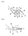
- the tool body 11 of the throwaway bite detachably fitted with the tip has a rectangular pillar as shown in Figs. 1 and 2 in the present embodiment, and the upper portion of a longitudinal end (left in Figs. 1 and 2) of a side surface 11A thereof is indented to serve as a tip fitting seat 12.
- the tip fitting seat 12 includes a fitting seat bottom 12A indented parallel to the side surface 11A, a fitting seat wall 12B which is raised vertically from the bottom 12A and which is perpendicular to the side surface 11A and the end surface 11B of the tool body 11 and parallel to the upper surface 11C of the tool body 11, and a fitting seat wall 12C which is raised to intersect the fitting seat bottom 12A at an acute angle and to be oblique toward the end as it goes to the side surface 11A as shown in Figs. 2 to 4 and which extends oblique in the direction intersecting the wall 12B at an acute angle and reaches the upper surface 11C as shown in Fig. 1.
- intersection angles of the fitting seat walls 12B and 12C as seen from the side surface 11A are equal to the intersection angle which is formed at the acute ends of the side surfaces 2A and 2B by the circumferential surfaces 3A and 3B of the tip body 1.
- the intersection angle formed by the wall 12C and the bottom 12A is equal to the angle between the slope portion, close to the side surface 2A, of the mountain-shaped section of the circumferential surface 3B serving as the clearance surface of the tip body 1 and the center of the plane shape of the side surface 2B.
- the tip body 1 is seated on the tip fitting seat 12 by opposing the side surface 2B to the bottom 12A, bringing the portion protruded by a step into close contact with the bottom, bringing one circumferential surface 3A into contact with the fitting seat wall 12B, bringing the slope portion of the circumferential surface 3B, intersecting the circumferential surface 3A at the cutting edge 4, into contact with the fitting seat wall 12C, and protruding a cutting edge 4 opposite to the cutting edge 4 from the end of the tool body 11. Therefore, the flat plane protruded by a step at the center of the side surface 2B becomes a seating surface onto the fitting seat bottom 12A.
- a clearance portion 12D for avoiding interference with the cutting edge 4 is formed so as to extend along the wall 12C tilted about the wall 12B, as shown in Fig. 1 in the embodiment.
- a clamp member 13 having a shaft portion 13A which is inserted into the fitting hole 5 of the tip body 1 and a head portion 13B with an outer diameter larger than that of the shaft portion 13A is fitted to the tool body 11.
- the clamp member 13 can advance and retreat in the direction along the central axis line O of the shaft portion 13A.
- the back surface 13C of the head portion 1B comes in contact with the contact portion 5B of the opening of the fitting hole 5, thereby clamping the tip body 1.
- the back surface 13C of the head portion 13B of the clamp member 13 is formed to have a circular section perpendicular to the central axis line O, and the head portion 13B of the clamp member 13 can pass through the fitting hole 5 of the tip body 1.
- the shaft portion 13A of the clamp member 13 is formed in a cylinder shape centered on the axis line O.
- the head portion 13B is formed integrally with the shaft portion 13A at one end of the clamp member 13 (left-lower side in Figs. 3 and 4) and is formed in a disk shape which is flat in the direction along the axial line O around the axis line O.
- the back surface 13C has a circular cone shape in which the outer diameter decreases toward the other end of the clamp member 13 (toward the shaft portion 13A, that is, toward the upper-right side in Figs. 3 and 4), so that the section perpendicular to the axis line O has a circle shape as described above.
- the inner diameter of the minimum-diameter portion 5A is smaller than the outer diameter of the head portion 13B having a disk shape of the clamp member 13.
- the angle of the back surface 13C having the circular cone shape about the axis line O is 45° or more in the embodiment.
- the circumferential portion of the end surface of the head portion 13B forms a semi-circular shape in the section taken along the axis line O, the center portion is a flat plane perpendicular to the axis line O, and an inserting hole into which a working tool such as a wrench is inserted so as to revolve the clamp member 13 around the axis line O is formed in the center portion.
- a cylindrical large-diameter portion 13E which is centered on the axis line O and has an outer diameter larger than the inner diameter of the minimum-diameter portion 5A is formed integrally with the shaft portion 13A. Accordingly, the large-diameter portion 13E has an outer diameter larger than that of the shaft portion 13A or the head portion 13B, and is a portion having the largest diameter of the clamp member 13.
- a male screw 13F is formed on the outer circumference of the large-diameter portion 13E, and an inserting hole 13D into which the working tool such as wrench is inserted so as to revolve the clamp member 13 around the axis line O is formed in the other end surface of the large-diameter portion 13E.
- a screw hole 12E penetrating from the fitting seat bottom 12A of the tip fitting seat 12 to the side surface 11D of the tool body 11 opposite to the side surface 11A is formed in the tool body 11 so as to be open correspondingly to the opening, close to the side surface 2B, of fitting hole 5 of the tip body 1 seated as described above. Accordingly, the clamp member 13 is fitted to the tool body 11 by inserting the male screw portion 13F on the outer circumference of the large-diameter portion 13E into the screw hole 12E so as to protrude the shaft portion 13A and the head portion 13B from the fitting seat bottom 12A.
- the clamp member 13 advances toward the tip fitting seat 12 so that the large-diameter portion 13E is indented from the fitting seat bottom 12A as shown in Fig. 3.
- the clamp member 13 retreats from the tip fitting seat 12 so that the large-diameter portion 13E is protruded from the fitting seat bottom 12A.
- the screw hole 12E is tilted with respect to the fitting seat bottom 12A of the tip fitting seat 12.
- the central axis line O of the clamp member 13 in which the male screw portion 13F is inserted into the screw hole 12E is tilted with respect to the fitting seat bottom 12A. Accordingly, the screw hole 12E is tilted with respect to the center line C of the tip body 1 seated on the tip fitting seat 12. Therefore, the direction in which the axis line O is tilted toward the advancement direction (inserting direction) of the clamp member 13 at the time of clamping from the fitting seat bottom 12A is a direction directed to the intersection between the fitting seat walls 12B and 12C along the section indicated by a reference numeral ZZ in Fig.
- An angle ⁇ of the tilted central axis line O of the clamp member 13 about the direction perpendicular to the fitting seat bottom 12A, that is, the direction along the center line C of the tip body 1 seated on the tip fitting seat 12, is in the range of 5° to 40° in the embodiment.
- the back surface 13C of the head portion 13B having a circular section comes in contact with the contact portion 5B close to the opposite side (the side toward the axis line O is tilted about the center line C) of the cutting edge 4 protruded from the end of the tool body 11 for use in cutting among a pair of contact portions 5B of the fitting hole 5 and presses the tip body 1 toward the fitting seat bottom 12A, thereby clamping the tip body 1 to the tip fitting seat 12.
- the clamp mechanism having the above-mentioned structure, since it is not necessary to detach the clamp member 13 from the tool body 11 at the time of detaching the tip, it is possible to easily perform the detachment and attachment work and thus there is not possibility of losing the detached clamp member 13.
- the back surface 13C of the head portion 13B of the clamp member 13 pressing the tip body 1 can have a disk shape of which the section is circular and the fitting hole 5 of the tip body 1 can have the minimum-diameter portion 5A of which the section transmitting the head portion 13B is circular, it is possible to simplify the shape of the clamp member 13 or the tip body 1, thereby reducing the cost for the clamp mechanism.
- the fitting hole 5 has the circular minimum-diameter portion 5A and the contact portions 5B are formed in the opening thereof, it is possible to reduce the portion of the tip body 1 cutting out by the fitting hole 5. Accordingly, it is possible to secure the strength of the tip body 1 and to prevent the destruction thereof due to a load at the time of cutting, thereby elongating the lift time of the tip and promoting the smooth cutting work.
- the contact portions 5B are formed in the opening of the fitting hole 5
- the contact portions 5B are formed as concave portions indented from the side surface 2A so as to form the crescent shape which is convex from the inner diameter of the minimum-diameter portion 5A as the inner circumference of the fitting hole 5 toward the outer circumference as seen in the direction along the center line C of the fitting hole 5.
- the contact portions 5B coming in contact with the back surface 13c can be formed by the size, corresponding to the back surface 13C coming in contact with the contact portions 5B, in the opening of the fitting hole 5 in which the disk-shaped head portion 13B having the back surface 13C with a circular section passes through the minimum-diameter portion 5A, it is possible to further suppress the portion of the tip body 1 cut out by the fitting hole 5 including the contact portions 5B, thereby more surely preventing the destruction of the tip body 1.
- the contact portions 5B are formed in a bell shape which is indented in the section taken along the center line C of the fitting hole 5 of the tip body 1 so as to form a quarter convex circle shape, but may be formed in, for example, a countersink shape with a concave circular-cone shape which is directed to the side surface 2B serving as the seating surface on the fitting seat bottom 12A of the tip fitting seat 12 as it goes to the inner circumference with the same slope as the slope of the back surface 13C of the head portion of the clamp member 13 which comes in contact with the contact portions 5B.
- the crescent shape formed toward the center line C by the contact portions 5B may be a longitudinal circular shape obtained by deviating the inner circumference of the minimum-diameter portion 5A, in addition to the elliptical shape like in the embodiment.
- the head portion 13B has a flat elliptical shape having a minor axis in the direction in which the central axis line O is tilted (in the major axis direction of the ellipse formed by the contact portions 5B in the embodiment) as seen in the direction along the center line C.
- the minimum-diameter portion 5A of the fitting hole 5 transmitting the head portion 13B can be formed in an elliptical shape having a minor axis in the direction in which the central axis line O is tilted as seen in the direction along the center line C, and thus the portion of the tip body 1 cut out by the fitting hole 5 can be further reduced. As a result, it is possible to improve the destruction preventing effect result from the further increase in strength of the tip.
- the contact portions 5B and the back surface 13C of the head portion 13B of the clamp member 13 may come in contact with each other over the whole circumference of the respective contact portions 5B, may come in contact with each other only at one position of the place in which the width from the inner circumference of the minimum-diameter portion 5A of each crescent contact portion 5B (the place in the major axis of the contact portions 5B forming an elliptical shape), or may come in contact with each other at both positions in the circumferential direction of the fitting hole 5 with the place having the largest width therebetween.
- a slight gap exists between the place in which the contact portions 5B have the larges width in the section (Z-Z section) taken along the major axis direction of the ellipse and the back surface 13C of the head portion 13B.
- the tip body 1 is clamped regardless of the rotational position around the central axis line O of the clamp member 13 by bringing the back surface 13C of the head portion 13B of the clamp member 13 with a circular section into contact with the contact portions 5B, it is possible to employ the structure in which the clamp member 13 advances and retreats while rotating over the entire circumference of the central axis line O, that is, the structure in which the clamp member 13 advances and retreats by means of the screw coupling between the male screw portion 13F and the screw hole 12E like in the embodiment.
- the central axis line O of the clamp member 13 is tilted with respect to the center line C of the fitting hole 5 of the tip body 1. Accordingly, when the back surface 13C of the head portion 13B is brought into contact with the contact portions 5B to press the tip body 1 by advancing the clamp member 13 toward the tip fitting seat 12 in the direction along the axis direction O, the tip body 1 is pressed toward the fitting seat bottom 12A of the tip fitting seat 12 in the direction along, and is also pressed in the direction in which the axis line O goes apart from the center line C toward the tip fitting seat 12 the central axis line C in the direction perpendicular to the center line C.
- the tilt angle ⁇ of the central axis line O of the tilted clamp member 13 about the center line C of the fitting hole 5 of the tip body 1 is preferably in the range of 5° to 40° like in the embodiment.
- the clearance portion for avoiding the interference of the tilted clamp member 13 with the shaft portion 13A is formed in the opening of the fitting hole 5 close to the side surface 2B serving as the seating surface on the tip fitting seat 12, for example, so that the fitting hole 5 is symmetrical inside and outside like in the embodiment, and is formed preferably in the shape of an ellipse elongated in the direction in which the clamp member 13 is tilted.
- the large-diameter portion 13E having a diameter larger than that of the fitting hole 5 of the tip body 1 and larger than that of the shaft portion 13A or the head portion 13B is formed on the end (the other end) of the clamp member 13 opposite to the head portion 13B at one end of the shaft portion 13A, and the male screw portion 13R is formed on the outer circumference of the large-diameter portion 13E.
- the large-diameter portion 13E can be protruded from the fitting seat bottom 12A to push up the center of the side surface 2B serving as the seating surface of the tip body 1 as shown in Fig. 4, thereby floating the tip body 1 from the tip fitting seat 12.
- the male screw portion 13F is formed to have a diameter larger than that of the fitting hole 5, that is, to be the large-diameter portion 13E of the clamp member 13 having a diameter larger than that of the shaft portion 13A.
- the male screw portion 13F may have a diameter equal to or smaller than that of the shaft portion 13A only in order to clamp the tip body 1, that is, the large-diameter portion 13E may not be formed in the clamp member 13.
- the large-diameter portion 13E may have a diameter smaller than that of the fitting hole 5, if only it comes in contact with side surface 2B or the inside of the fitting hole 5 so as to push up the tip body 1 when the male screw portion 13F is loosened.
- the tip in which the cutting edge 4 is formed on the intersection ridgelines at the acute ends of the parallelogram side surfaces 2A and 2B among the intersection ridgelines between four circumferential surfaces 3A and 3B of the tip body 1 substantially having a parallelogram panel shape has been described as the clamped tip.
- the clamp mechanism according to the embodiment is not limited to the above-mentioned tip.
- Figs. 8 and 9 illustrate a grooving tip according to a second embodiment which can be fitted to the tool body according to the first embodiment.
- like elements common to the first embodiment are denoted by like reference numerals and description thereof will be simplified or omitted.
- an axis-shaped cutting edge portion 6 is protrude from one short circumferential surface 3B of the tip body 1 having a parallelogram shape along the long circumferential surface 3A intersecting each other at an acute end of the side surfaces 2A and 2B, a cut portion 6A is formed on the circumferential surface 3A at the end of the cutting edge portion 6, the upper surface of the cut portion 6A opposed to the circumferential surface 3A serves as a rake face, and the cutting edge 4 is formed on the protruded end.
- both side surfaces 2A and 2B are not a slope surface, a portion protruded by a step is not formed at the center of the side surface 2B, both side surfaces 2A and 2B are flat planes perpendicular to the thickness direction of the tip body 1 (the direction along the center line C of the fitting hole 5), and the tip body 1 is not symmetrical about the center line C.
- the invention is applied to a throwaway turning bite.
- the tip body 1 has a rhombus panel shape, one of a pair of rhombus side surfaces 2A and 2B (side surface 2A in the figures) serves as a rake face, the cutting edge 4 having a corner portion 4A at the acute end of the rhombus shape is formed at four ridges, the circumferential surfaces 3D of the tip body 1 extending to the cutting edge 4 serve as the clearance surfaces, and the circumferential surfaces 3D serving as the clearance surfaces are gradually retreated toward the side surface 2B, thereby forming a positive tip a clearance angle.
- the side surface 2B serving as a seating surface inside the tip body 1 has a rhombus shape slightly smaller than the side surface 2A serving as the rake face.
- the fitting hole 5 is not symmetrical about a plane perpendicular to the center line C at the center in the thickness direction of the tip body 1, and the inner circumference of the opening closer to the side surface 2B than to the minimum-diameter portion 5A has a counterbore hole shape having an inner diameter larger than that of the contact portion 5B.
- the tool body 11 by which the tip is clamped has a rectangular pillar shape like the first embodiment, but the end surface 11B has a triangular gable shape corresponding to the acute corner of the rhombus of the tip body 1.
- the tool body is gradually retreated as it goes apart from the upper surface 11C to correspond to the clearance angle given to the circumferential surfaces 3D serving as the clearance surface of the positive tip body 1, and the tip fitting seat 12 is opened toward the end surface 11B at the end of the upper surface 11C.
- the tip fitting seat 12 includes a fitting seat bottom 12A having a rhombus shape equal to but smaller than the side surface 2B serving as the seating surface of the tip body 1 and a pair of fitting seat walls 12B and 12C which are raised from the ridge on the end side of the tool body 11 in the rhombus of the fitting seat bottom 12A toward the upper surface 11C and in which a portion close to the upper surface 11C is tilted to correspond to the clearance angle given to the circumferential surface 3D.
- the portion close to the fitting seat bottom 12A is formed in a shaft portion 12F having a diameter slightly larger than a female screw portion.
- the clamp mechanism according to the invention can be applied as a tip clamp mechanism of a throwaway turning tool such as a front milling tool like the fourth embodiment shown in Figs. 13 to 15, in addition to the throwaway cutting tool like the first to third embodiments.
- the tool body 11 of the front milling tool has substantially a disk shape centered on the axis line Z and rotates in the rotation direction T at the time of cutting.
- a tip pocket 14 is formed in a concave shape on the outer circumference
- a tip fitting seat 12 is formed in the wall of the tip pocket 14 directed to the rotation direction T so as to be open to the outer circumferential surface 11E and the lower surface 11F of the tool body 11, and the tip body 1 is clamped and fitted by the use of the clamp mechanism according to the fourth embodiment.
- a plurality of tip pockets 14, a plurality of tip fitting seats 12, a plurality of tip bodies 1, and a plurality of tip clamp mechanisms are installed with a gap in the circumferential direction of the tool body 11, but only one is shown in the embodiment and others are omitted.
- the tip body 1 has substantially a square panel shape as shown in Fig. 15, the cutting edges 4 having a corner R portion 4A at the edges of the side surface 2A are formed at four ridges of the square side surface 2A serving as the rake face, and a positive tip is formed in which a clearance angle is given to four circumferential surfaces 3D thereof like the third embodiment. Accordingly, by sequentially revolving the tip body 1 around the center line C and fitting again the tip body so as to locate the corner R portion 4A on the outer circumference of the lower surface 11F of the tool body 11, the cutting edges 4 can be used four times in one tip body 1.
- Figs. 16 to 20 illustrate the fifth embodiment of the invention.
- the tip according to the fifth embodiment has a structure that the axial cutting edge portion 6 is protruded along the longitudinal circumferential surface 3A from the short circumferential surface 3B of the tip body 1 having substantially parallelogram panel shape and the cutting edge 4 is formed at the end thereof and is used to perform the inner-diameter machining process to a lower opening formed in a workpiece.
- a plurality of fitting holes 5 (two in the embodiment) is formed in the tip body 1, and a plurality of clamp members 13 (two in the embodiment) are provided in the tip fitting seat 12 of the tool body 11 to correspond to the fitting holes 5.
- the fitting holes 5 are formed in parallel to each other in the direction in which the circumferential surface 3A extends (in the horizontal direction in Fig. 16) as shown in Fig. 16 so that the fitting holes 5 extend in the thickness direction of the tip body 1 in the state where the center lines C thereof are parallel to each other as shown in Fig. 19, and the contact portions 5B having a substantially crescent shape as seen from the side surface 2A of the tip body 1 are formed in the fitting holes 5, respectively.
- the openings of the fitting holes 5 have an elliptical shape as seen in the direction along the center lines C, but in the contact portions 5B according to the embodiment, the section taken along the center line C does not form a convex quarter circular shape, unlike the first to fourth embodiments.
- the contact portion 5B is formed substantially in a straight line shape directed to the side surface 2B with a constant slope as it goes toward the inner circumference of the fitting hole 5 from the side surface 2A of the tip body in which the corresponding contact portion is formed as shown in Fig. 19.
- the slope of a straight line formed by the contact portion 5B in the section containing the center line C is slowest in the plane P containing the center line C and the major axis of the ellipse and is continuously faster as it goes toward the minor axis around the center line C along the ellipse.
- the position of the straight line in direction along the center line C is gradually retreated toward the side surface 3B from the side surface 2A as it goes toward the minor axis around the center line C from the plane P containing the center line C and the major axis.
- the contact portion 5 is most convex in the direction along the center line C in the plane P (in the major axis).
- the fitting hole 5 is symmetrical about the plane perpendicular to the center line C at the center in the thickness direction of the tip body 1, similarly to the first embodiment. Accordingly, in the minimum-diameter portion 5A of the fitting hole 5 inside the contact portion 5B, the width in the direction along the center line C is decreased as it goes from the major axis of the ellipse toward the minor axis around the center line C, as shown in Fig. 19.
- Two fitting holes 5 formed in the tip body 1 have the same shape and size and as shown in Fig. 16, the major axes of the ellipses are parallel to each other, that is, the planes P are parallel to each other, as seen from the side surface 2A.
- the major axis of the fitting hole 5 formed at one acute end opposite to the end provided with the cutting edge portion 6 among the acute ends of the parallelogram of the side surface 2A extends toward the intersection between the circumferential surfaces 3A and 3B at one acute end, and the major axis of the fitting hole 5 formed at the other acute end provided with the cutting edge portion 6 extends toward the intersection between the circumferential surfaces 3A and 3B at the other acute end.
- the intersection at one acute end is chamfered in a circular arc shape smoothly tangential to the circumferential surfaces 3A and 3B.
- marks 15 indicating the clamping order at the time of clamping the tip by advancing the clamp members 13 provided corresponding to the fitting holes 5 are provided in the vicinity of the (two) fitting holes 5.
- the marks 15 are provided as numerals "1" and "2" by inscribing in the side surface 2A the order of clamping the clamp members 13 passing through the adjacent fitting holes 5 by means of a laser marking process.
- numeral "1" is marked at one acute end among the acute ends of the parallelogram of the side surface 2A and numeral "2" is marked at the other acute end.
- screw holes 12E are formed at positions corresponding to the fitting holes 5 in the state where the tip bodies 1 are fitted.
- the screw holes 12E are formed so that the central axis lines O of the clamp members 13 inserted into the screw holes 12E are parallel to each other in the plane P containing the center lines C of the fitting holes 5 and the major axes thereof in the fitting state and extend to be apart from the center lines C and to be tilted about the center lines C in the direction directed to one acute end of the tip body 1 as it goes in the advancement direction (the inserting direction of the clamp members 13) of the clamp members 13 toward the tip fitting seat 12.
- the portions 5C positioned in the plane P containing the center lines C and the central axis lines 0, that is, the portions positioned in the major axis, are slowest in slope about the plane perpendicular to the center line C as described above and are most convex in the direction along the center line C. Accordingly, the portions 5C positioned in the plane P containing the central axis lines O and the center lines C are most convex in the direction along the central axis lines O.
- the back surfaces 13C of the head portions 13B of the clamp members 13 come in contact with the portions 5C positioned in the plane P among the contact portions 5B, as the clamp members 13 are inserted in the direction along the central axis lines O to advance toward the tip fitting seat 12.
- the back surface 13C of the head portion 13B comes in contact with the portion 5C positioned in the plane P in the circumferential direction among the contact portions 5B of the fitting hole 5 of the tip body 1 and presses the tip body 1. Accordingly, for example, in comparison with the case that the back surface 13C of the head portion 13B comes in contact with two positions in the circumferential direction of the contact portions 5B in the first embodiment, it is possible to satisfactorily and stably clamp the tip by efficiently delivering the pressing force without distributing the pressing force of the clamp member 13 (the inserting force resulting from the male screw 13F in the embodiment).
- the clamp member 13 is a clamp screw for advancing toward the tip fitting seat 12 and clamping the tip body 1 by inserting the male screw portion 13F into the screw hole 12E, it is possible to prevent the partial wear due to the contact of the back surface 13C with the contact portion 5B at a plurality of positions.
- the central axis lines O tilted about the center lines C of the clamp members 13 are parallel to each other as seen in the direction along the center line C, but may extend in the direction intersecting each other as seen in the direction along the center line C if only the intersection angle is 5° or less.
- the central axis lines O of the clamp members 13 are disposed preferably to intersect each other at one acute end even if the central axis lines extend in the directions intersecting each other as seen in the direction along the center lines C as described above.
- a plurality of fitting holes 5 are formed in the tip body 1, a plurality of clamp members 13 corresponding to the fitting holes are disposed in the tool body 11, and the marks 15 indicating the order of advancing (inserting in the embodiment) the clamp members 13 toward the tip fitting seat 12 are formed in the tip body 1.
- a mark 15 indicated by numeral "1" is formed in the vicinity of the fitting hole 5 close to one acute end of the tip body 1 and located at the intersection between the walls 12B and 12C of the tip fitting seat 12, and a mark 15 indicated by numeral "2" is formed in the vicinity of the fitting hole 5 close to the other acute end opposite thereto.
- the tip body 1 is first fitted to the tip fitting seat 12, the clamp member 13 of which the shaft portion 13A passes through the fitting hole 5 close to one acute end in the vicinity of the mark 15 indicated by numeral "1" is further inserted thereto, and then the clamp member 13 is inserted into the fitting hole 5 close to the other acute end in the vicinity of the mark 15 indicated by numeral "2", thereby clamping a tip.
- the tip body 1 is strongly pressed in the direction in which the central axis line O is tilted in the extending direction of the plane P, that is, toward the acute end in which the walls 12B and 12C of the tip fitting seat 12 intersect each other by advancing the clamp member 13 of one acute end toward the tip fitting seat 12. Thereafter, the circumferential surfaces 3A and 3B intersecting each other at one acute end come in contact with the walls 12B and 12C as a whole, and then is pressed by the clamp member 13 at the other acute end, thereby strongly fitting the tip body, as described above.
- the tip is positioned in the state where the circumferential surface 3A of the tip body 1 and the wall 12B of the tip fitting seat 12 or the circumferential surface 3B and the wall 12C do not come in contact with each other as a whole by first inserting the clamp member 13 passing through the fitting hole at the other acute end, the clamp member 13 at one acute end is then inserted and the clamp member 13 is clamped in this state, the edge position of the cutting edge 6 is not positioned with high accuracy, and the machining accuracy is damaged or the tip becomes unstable, thereby causing a rattle or a detachment in the course of performing the cutting process.
- the marks 15 are formed by inscribing numerals "1" and "2" in the side surface 2A of the tip body 1 by the use of the laser marking.
- the marks may be formed by forming the numerals in the tip body 1 in a concave manner or a convex manner, or by forming the number of protrusions or grooves other than the numerals in the vicinity of the fitting holes 5 to correspond to the numerals.
Landscapes
- Engineering & Computer Science (AREA)
- Mechanical Engineering (AREA)
- Cutting Tools, Boring Holders, And Turrets (AREA)
Abstract
Description
- The present invention relates to a clamp mechanism of a tip for detachably fitting a throwaway tip (hereinafter, simply referred to as a tip), in which a fitting hole is formed through a tip body, into a tip fitting seat formed in a tool body by the use of a clamp member, and more particularly, to a clamp mechanism of a tip in which the tip can be attached to or detached from a tool body without completely separating a clamp member from the tool body.
- In such a kind of clamp mechanisms, it is general to press all or a part of an opening of a fitting hole with a head portion and to clamp a tip, by setting the outer diameter of a shaft portion of a clamp member to be smaller than the inner diameter of the fitting hole formed in a tip body, setting the outer diameter of the head portion formed at an end of the shaft portion to be larger than that, forming a screw portion inserted into a tip fitting seat of a tool body at the other end of the shaft portion, positioning the tip body onto the tip fitting seat, and then inserting the clamp member into the fitting hole from the screw portion. However, in the clamp mechanism, since the clamp member should be also detached from the tool body when the tip is detached, the detachment work is troublesome and the detached clamp member may be lost.
- In
Patent Documents 1 to 3, there have been suggested clamp mechanisms in which a head portion of a clamp member disposed in a tool body to advance and retreat has a section with a non-circular cross section which has a protrusion protruded from the outer circumference of a shaft portion, such as a petal shape, a triangular shape or a cross shape, not a circular shape and in which a concave portion through which the protrusion can pass and a convex portion which engages with the protrusion are alternately formed in the circumferential direction on the inner circumference of an opening of a fitting hole. In such clamp mechanisms, at the time of detaching a tip, the clamp member is protruded, and the tip is pulled out by rotating a tip body or a clamp member so as to position the protrusion and the concave portion with respect to each other. On the other hand, at the time of clamping the tip, the head portion is allowed to pass through the fitting hole in a state where the protrusion and the concave portion are positioned with respect to each other, the tip body or the clamp member is rotated so as to position the protrusion and the convex portion with respect to each other, and then the convex portion is pressed and clamped by the protrusion by inserting the clamp member so as to advance the clamp member toward a tip fitting seat. - In
Patent Document 4, there has been suggested a clamp mechanism in which a clamp hole portion through which a shaft portion of a clamp member having a screw portion can pass but a head portion cannot pass is formed in a tip body, a passing hole through which the head portion can pass is formed on at least one side of an opening of the clamp hole, the shaft portion can pass between the clamp hole and the passing hole, the tip body is fitted to the tip fitting seat by allowing the head portion to pass through the passing hole at the time of fitting a tip in a state where a clamp member inserted into the tip fitting seat is not completely detached therefrom but is loosened, the tip body is brought into contact with the wall surface of the tip fitting seat so as to position the tip body and to allow the shaft portion to pass through the clamp hole by allowing the tip body to slide, and then the opening of the clamp hole is pressed with the head portion to clamp the tip by inserting the clamp member in a screw manner. - Patent Document 1:
Japanese Unexamined Utility Model Publication No. 1973-12675 - Patent Document 2: PCT Japanese Translation Patent Publication No. 2002-512891
- Patent Document 3: U.S. Unexamined Patent Publication No.
US2003/0165362 - Patent Document 4:
Japanese Unexamined Patent Publication No. 1999-19808 - However, like
Patent Documents 1 to 3, in the clamp mechanisms in which the protrusion is formed in the head portion of the clamp member and the concave and convex portions are formed in the fitting hole of the tip body, the shape of the head portion of the clamp member and the shape of the fitting hole of the tip body are complicated and the tip can be attached or detached only if the convex portion of the fitting hole is accurately positioned with respect to the rotational position of the protrusion at the time of fitting the tip and the concave portion is accurately positioned with respect to the rotational position of the protrusion at the time of detaching the tip. Accordingly, a simple clamp member such as a clamp screw in which a screw portion is formed on the end of the shaft portion opposite to the head portion cannot be used, since the clamp member rotates and moves toward the tip fitting seat as a whole at the time of fitting the tip and thus it is difficult to position the protrusion and the convex portion with respect to each other. In addition, since the structure for allowing the clamp member to advance and retreat at the time of fitting the tip is complicated, it is not possible to avoid increase in cost. - On the other hand, in the clamp mechanism described in
Patent Document 4, the clamp hole through which the shaft portion can pass communicates with the fitting hole of the tip body so as to be adjacent to the passing hole with a large diameter through which the head portion of the clamp member can pass, the portion of the tip body cut off to form the fitting hole is enlarged to deteriorate the strength of the tip, thereby causing destruction of the tip body in some cases. In the clamp mechanism described inPatent Document 4, as described above, since the tip body is brought into contact with the wall surface of the tip fitting seat and is positioned by allowing the tip body in which the head portion of the clamp member passes through the passing hole to slide, the shaft portion is allowed to pass through the clamp hole, and then the clamp member is inserted in a screw manner to clamp the tip, the tip body is supported only by friction based on a pressing force of the head portion of the clamp member in a direction opposite to the sliding direction of the tip body, that is, in a direction against the wall surface of the tip fitting seat. Accordingly, when a large force acts in the direction at the time of cutting or the like, the tip can easily depart and move. - The present invention is contrived in view of the above-mentioned problems. It is an object of the invention to provide a clamp mechanism of a tip in which the shape of the head portion of the clamp member or the shape of the fitting hole of the tip body is not complicated and the tip body is prevented from being greatly cut off by the fitting hole, thereby securing the strength of the tip. It is another object of the invention to provide a clamp mechanism in which the structure for advancing the clamp member toward the tip fitting seat at the time of detaching or attaching the tip or clamping the tip can be simplified and in which the tip can be strongly and satisfactorily supported in the direction against the wall surface of the tip fitting seat when the tip body is brought into contact with the wall surface and is positioned.
- In order to solve the above-mentioned problems and accomplish the above-mentioned objects, according to an aspect of the present invention, there is provided a clamp mechanism of a tip for pressing the tip, in which a fitting hole is formed through a tip body, by the use of a head portion of a clamp member having a shaft portion inserted into the fitting hole and the head portion with an outer diameter larger than that of the shaft portion and thus clamping the tip to a tip fitting seat by allowing the clamp member to advance toward the tip fitting seat of a tool body in the central axis direction of the shaft portion. In the clamp member, a section, which is perpendicular to the central axis direction, of the back surface of the head portion has a circle shape centered at the central axis line. In the tip body of the tip, the head portion of the clamp member can pass through the fitting hole, and a contact portion with which a part of the back surface of the head portion comes in contact when the clamp member is allowed to advance is formed in an opening of the fitting hole. Advantages of the Invention
- In the above-mentioned clamp mechanism, at the time of clamping the tip, the tip body is mounted on the tip fitting seat by allowing the head portion to pass through the fitting hole of the tip body while the clamp member is fitted to the tool body in the state where the clamp member is allowed to slightly retreat from the tip fitting seat at the time of clamping the tip, the clamp member is then allowed to advance so as to bring a part of a back surface of the head portion into contact with the contact portion of the opening of the fitting hole and press the contact portion. Accordingly, at the time of detaching and attaching the tip, it is not necessary to separate the clamp member from the tool body and the back surface of the head portion of the clamp member may have a circular section described above, the fitting hole of the tip body may have a minimum circular section through which the head portion can pass. As a result, it is possible to simplify the shape of the head portion of the clamp member and the shape of the fitting hole of the tip body, thereby reducing the cost for the clamp mechanism. Specifically, it is possible to minimize the portion of the tip body cut off by the fitting hole, to secure the strength of the tip, and to prevent the destruction thereof, thereby elongating the life time of the tip. In addition, in order to more surely prevent the destruction of the tip body, the contact portion of the tip body may have a crescent shape which is convex from the inner circumference of the fitting hole toward the outer circumference as seen in the direction along the center line of the fitting hole, thereby reducing the cut-off portion of the tip body.
- In order to advance the clamp member toward the tip fitting seat to clamp the tip in which the head portion of the clamp member has passed through the fitting hole, for example, as described in
Patent Documents 1 to 3, the structure for allowing the clamp member to advance and retreat without varying the rotational position of the clamp member around the central axis line of the shaft portion can be employed. However, since the clamp member of the above-mentioned clamp mechanism presses and clamps the tip body by bringing a part of the head portion having a circular section into contact with the contact portion on the opening of the fitting hole and can clamp the tip body regardless of the rotational position of the clamp member around the axial line. That is, since a screw portion inserted into the tool body is disposed as the clamp member at the end of the shaft portion opposite to the head portion, it is possible to use the clamp member which advances toward the tip fitting seat while rotating over the whole circumference of the central axis line, that is, a simple clamping screw corresponding to the back shape of the head portion. As a result, by using such a clamp member, it is possible to sufficiently secure the pressing force at the time of clamping the tip body and to further simplify the structure of the clamp mechanism for allowing the clamp member to advance and retreat at the time of attaching and detaching the tip, thereby further reducing the cost. - Specifically, when the tip body is brought into contact with the wall surface of the tip fitting seat for the purpose of positioning, the central axis line of the clamp member may be tilted with respect to the center line of the fitting hole. That is, by tilting the central axis line in the direction in which the central axis line is spaced apart from the center line of the fitting hole toward the tip fitting seat to ward which the clamp member is allowed to advance at the time of clamping, the tip body is pressed toward the wall surface by the back surface of the head portion of the clamp member, thereby preventing the tip body from departing and moving toward the opposite side of the wall surface. In the clamp member, since the large-diameter portion having an outer diameter larger than that of the fitting hole is provided at the end of the shaft portion opposite to the head portion, the tip body can be floated from the tip fitting seat by the use of the large-diameter portion by retreating the clamp member from the tip fitting seat at the time of detaching the tip. Accordingly, the detachment work can be more easily performed.
- In addition, as described above, when the central axis line of the clamp member is tilted about the center line of the fitting hole, a portion, which is located in a plane including the central axis line of the clamp member and the center line of the fitting hole, of the contact portion may be more convex in the direction along the central axis line than other portions. In this case, the back surface of the head portion of the clamp member comes in contact with the contact portion to press the tip body at a portion, on the plane which is most convex along the central axis line, of the contact portion as the clamp member advances toward the tip fitting seat along the central axis line. Accordingly, the pressing force from the clamp member can be efficiently delivered without being distributed, thereby clamping the tip. Specifically, when the clamp member is the above-mentioned clamp screw, it is possible to prevent the partial abrasion.
- Similarly, when the central axis line of the clamp member is tilted about the center line of the fitting hole, a plurality of fitting holes having the center lines parallel to each other may be formed in the tip body, a plurality of clamp members corresponding to the fitting holes may be provided in the tool body, and the tilted central axis lines of the clamp members may extend in a parallel direction or in a direction intersecting each other at an intersection angle of 5° or less as seen in the direction along the center lines. In this case, the pressing directions of the plurality of clamp members of which the central axis lines are tilted can be arranged in a constant direction to bring the tip body into contact with the wall surface or position the tip body, thereby improving the accurate repeated positioning of the edge of the tip. In this way, when a plurality of fitting holes is formed in the tip body and a plurality of clamp members is provided in the tool body, a mark indicating an order of allowing the clamp members to advance (inserting the clamp screw in a screw manner) toward the tip fitting seat may be provided in the tip body. In this case, it is possible to more surely guide the tip body in the constant direction and to position the tip body, thereby further improving the accurate repeated positioning of the edges.
-
- Fig. 1 is a lateral view illustrating a throwaway grooving bite employing a clamp mechanism according to a first embodiment of the present invention.
- Fig. 2 is a plan view of the grooving bite shown in Fig. 1.
- Fig. 3 is a cross-sectional view taken along Line Z-Z of Fig. 1, which illustrates a state in which a tip is clamped according to the first embodiment of the invention.
- Fig. 4 is a diagram illustrating a state in which a
clamp member 13 is loosened from the state shown in Fig. 3. - Fig. 5 is a perspective view of the clamped tip according to the first embodiment.
- Fig. 6 is a lateral view of the tip shown in Fig. 5.
- Fig. 7 is a plan view of the tip shown in Fig. 5.
- Fig. 8 is a lateral view of a clamped tip according to a second embodiment of the invention.
- Fig. 9 is a plan view of the tip shown in Fig. 8.
- Fig. 10 is a plan view illustrating a throwaway grooving bite employing a clamp mechanism according to a third embodiment of the invention.
- Fig. 11 is a lateral view of the grooving bite shown in Fig. 10.
- Fig. 12 is a cross-sectional view taken along Line Z-Z of Fig. 10, which illustrates a state in which a tip is clamped according to the third embodiment of the invention.
- Fig. 13 is a perspective view illustrating a throwaway face mill employing a clamp mechanism according to a fourth embodiment of the invention.
- Fig. 14 is a partially exploded lateral view illustrating a state in which a
clamp member 13 of the face mill shown in Fig. 13 is loosened. - Fig. 15 is a lateral view of a clamped tip in the face mill shown in Fig. 13 as seen from a
side surface 2A. - Fig. 16 is a lateral view of a clamped tip according to a fifth embodiment of the invention.
- Fig. 17 is a plan view of the tip shown in Fig. 16.
- Fig. 18 is a front view of the tip shown in Fig. 16.
- Fig. 19 is a cross-sectional view taken along Line X-Y-Y-X of Fig. 16.
- Fig. 20 is a cross-sectional view of a throwaway bite employing a clamp mechanism according to the fifth embodiment of the invention, which corresponds to the section taken along Line X-Y-Y-X of Fig. 16.
-
- 1: TIP BODY
- 4: CUTTING EDGE
- 5: FITTING HOLE
- 5A: MINIMUM-DIAMETER PORTION OF
FITTING HOLE 5 - 5B: CONTACT PORTION
- 5C: PORTION OF
CONTACT PORTION 5B LOCATED IN PLANE P - 11: TOOL BODY
- 12: TIP FITTING SEAT
- 12A: BOTTOM SURFACE OF TIP FITTING SEAT
- 12B, 12C: WALL SURFACE OF TIP FITTING SEAT
- 12E: SCREW HOLE
- 13: CLAMP MEMBER
- 13A: SHAFT PORTION
- 13B: HEAD PORTION
- 13C: BACK SURFACE OF
HEAD PORTION 13B - 13E: LARGE DIAMETER PORTION
- 13F: MALE SCREW PORTION
- 15: MARK
- C: CENTER LINE OF
FITTING HOLE 5 - O: CENTRAL AXIS LINE OF CLAMP MEMBER
- P: PLANE INCLUDING CENTER LINE C AND CENTRAL AXIS LINE O
- Figs. 1 to 4 illustrate a throwaway grooving bite to which a clamp mechanism according to a first embodiment of the present invention is applied, and Figs. 5 to 7 illustrate a tip which is fitted to the clamp mechanism according to the first embodiment. A
tip body 1 of the tip is formed in a parallelogram panel shape out of a hard material such as cemented carbide, and has a pair ofside surfaces circumferential surfaces tip body 1. Acutting edge 4 is formed in each intersection ridgeline of thecircumferential surfaces cutting edges 4 of onetip body 1 can be utilized. - Accordingly, one of the
circumferential surfaces circumferential surface 3A in the present embodiment) serves as a rake face of thecutting edge 4, and the other (the shortcircumferential surface 3B in the present embodiment) serves as a clearance surface. Bothside surfaces cutting edges 4 gradually retreat in the thickness direction of thetip body 1 as it goes to the center of the side surfaces 2A and 2B from the acute ends, thereby giving clearance to thecutting edge 4. In thecircumferential surface 3A serving as the rake face of thecutting edge 4, a portion extending to thecutting edge 4 and a portion intersecting thecircumferential surface 3B at an obtuse angle form a flat plane located in the same plane parallel in the thickness direction, and aconcave portion 3C slightly retreating from the flat plane is formed between the portions. In thecircumferential surface 3B serving as the clearance surface of thecutting edge 4, the section other than a portion close to thecutting edge 4 has a mountain shape of a substantial triangle. - On the other hand, the center portions of the side surfaces 2A and 2B of the
tip body 1 form a flat plane perpendicular to the thickness direction, the center portion of theside surface 2B on the inner side of thetip body 1 is protruded by a step, and afitting hole 5 is formed between the center portions of the side surfaces 2A and 2B so as to pass through thetip body 1 in the thickness direction. In thefitting hole 5, the substantial center portion in the thickness direction of the tip body including the portion protruded by a step on theside surface 2B becomes a circular minimum-diameter portion 5A centered about the center line C and an opening of thefitting hole 5 directed to the outer side of the tip body along the center line C from the minimum-diameter portion 5A has an inner diameter, along the diagonal line connecting the acute ends of the parallelogram of theside surface 2A, which increases toward theside surface 2A. Here, the inner diameter in the direction perpendicular to the diagonal line is substantially equal to that of the minimum-diameter portion 5A. - The section of the opening of the
fitting hole 5 along the diagonal line connecting the acute ends form a convex quarter circle shape toward the side surfaces 2A and 2B of thetip body 1 from the minimum-diameter portion 5A as shown in Figs. 3 and 4, that is, a bell shape in which the inner diameter in the diagonal direction increases and the inner diameter increases in a straight line shape having a constant slope, thereby forming a concave portion indented from the side surfaces 2A and 2B. As seen along the center line C, in a portion of which the section forms the convex circle shape, the width with which the inner diameter increases from the inner circumference of the minimum-diameter portion 5A which is the inner circumference of thefitting hole 5 in the diagonal line is the maximum, as shown in Fig. 6, and the width gradually decreases as it goes apart from the diagonal line in the direction perpendicular to the diagonal line around the center line C, thereby forming a crescent shape which is convex from the inner circumference of thefitting hole 5 toward the outer circumference. Accordingly, in the opening of thefitting hole 5, as shown in Fig. 6, the opening edges toward the side surfaces 2A and 2B form an elliptical shape having a major axis along the diagonal line as seen along the center line C and form a crescent shape as seen from the center line C on theside surface 2A. A pair of which the section has the convex circle shape serves as thecontact portion 5B in the present embodiment. In the embodiment, thefitting hole 5 is symmetrical about a plane perpendicular to the center line C at the center in the thickness direction of thetip body 1 including the portion of theside surface 2B protruded by a step. - The
tool body 11 of the throwaway bite detachably fitted with the tip has a rectangular pillar as shown in Figs. 1 and 2 in the present embodiment, and the upper portion of a longitudinal end (left in Figs. 1 and 2) of aside surface 11A thereof is indented to serve as a tipfitting seat 12. Here, thetip fitting seat 12 includes afitting seat bottom 12A indented parallel to theside surface 11A, afitting seat wall 12B which is raised vertically from the bottom 12A and which is perpendicular to theside surface 11A and theend surface 11B of thetool body 11 and parallel to theupper surface 11C of thetool body 11, and afitting seat wall 12C which is raised to intersect the fitting seat bottom 12A at an acute angle and to be oblique toward the end as it goes to theside surface 11A as shown in Figs. 2 to 4 and which extends oblique in the direction intersecting thewall 12B at an acute angle and reaches theupper surface 11C as shown in Fig. 1. - The intersection angles of the
fitting seat walls side surface 11A are equal to the intersection angle which is formed at the acute ends of the side surfaces 2A and 2B by thecircumferential surfaces tip body 1. In addition, the intersection angle formed by thewall 12C and the bottom 12A is equal to the angle between the slope portion, close to theside surface 2A, of the mountain-shaped section of thecircumferential surface 3B serving as the clearance surface of thetip body 1 and the center of the plane shape of theside surface 2B. Accordingly, thetip body 1 is seated on thetip fitting seat 12 by opposing theside surface 2B to the bottom 12A, bringing the portion protruded by a step into close contact with the bottom, bringing onecircumferential surface 3A into contact with thefitting seat wall 12B, bringing the slope portion of thecircumferential surface 3B, intersecting thecircumferential surface 3A at thecutting edge 4, into contact with thefitting seat wall 12C, and protruding acutting edge 4 opposite to thecutting edge 4 from the end of thetool body 11. Therefore, the flat plane protruded by a step at the center of theside surface 2B becomes a seating surface onto the fitting seat bottom 12A. At corner at which thefitting seat walls clearance portion 12D for avoiding interference with thecutting edge 4 is formed so as to extend along thewall 12C tilted about thewall 12B, as shown in Fig. 1 in the embodiment. - As shown in Figs. 3 and 4, a
clamp member 13 having ashaft portion 13A which is inserted into thefitting hole 5 of thetip body 1 and ahead portion 13B with an outer diameter larger than that of theshaft portion 13A is fitted to thetool body 11. Here, theclamp member 13 can advance and retreat in the direction along the central axis line O of theshaft portion 13A. By advancing theclamp member 13 toward thetip fitting seat 12 along the central axis line O, theback surface 13C of the head portion 1B comes in contact with thecontact portion 5B of the opening of thefitting hole 5, thereby clamping thetip body 1. Theback surface 13C of thehead portion 13B of theclamp member 13 is formed to have a circular section perpendicular to the central axis line O, and thehead portion 13B of theclamp member 13 can pass through thefitting hole 5 of thetip body 1. - Here, the
shaft portion 13A of theclamp member 13 is formed in a cylinder shape centered on the axis line O. Thehead portion 13B is formed integrally with theshaft portion 13A at one end of the clamp member 13 (left-lower side in Figs. 3 and 4) and is formed in a disk shape which is flat in the direction along the axial line O around the axis line O. Theback surface 13C has a circular cone shape in which the outer diameter decreases toward the other end of the clamp member 13 (toward theshaft portion 13A, that is, toward the upper-right side in Figs. 3 and 4), so that the section perpendicular to the axis line O has a circle shape as described above. Accordingly, in thefitting hole 5 of thetip body 1, the inner diameter of the minimum-diameter portion 5A is smaller than the outer diameter of thehead portion 13B having a disk shape of theclamp member 13. The angle of theback surface 13C having the circular cone shape about the axis line O is 45° or more in the embodiment. The circumferential portion of the end surface of thehead portion 13B forms a semi-circular shape in the section taken along the axis line O, the center portion is a flat plane perpendicular to the axis line O, and an inserting hole into which a working tool such as a wrench is inserted so as to revolve theclamp member 13 around the axis line O is formed in the center portion. - At the end of the
clamp member 13 opposite to thehead portion 13B of theshaft portion 13A, that is, the other end of theclamp member 13, a cylindrical large-diameter portion 13E which is centered on the axis line O and has an outer diameter larger than the inner diameter of the minimum-diameter portion 5A is formed integrally with theshaft portion 13A. Accordingly, the large-diameter portion 13E has an outer diameter larger than that of theshaft portion 13A or thehead portion 13B, and is a portion having the largest diameter of theclamp member 13. Amale screw 13F is formed on the outer circumference of the large-diameter portion 13E, and an insertinghole 13D into which the working tool such as wrench is inserted so as to revolve theclamp member 13 around the axis line O is formed in the other end surface of the large-diameter portion 13E. - A
screw hole 12E penetrating from the fitting seat bottom 12A of thetip fitting seat 12 to theside surface 11D of thetool body 11 opposite to theside surface 11A is formed in thetool body 11 so as to be open correspondingly to the opening, close to theside surface 2B, offitting hole 5 of thetip body 1 seated as described above. Accordingly, theclamp member 13 is fitted to thetool body 11 by inserting themale screw portion 13F on the outer circumference of the large-diameter portion 13E into thescrew hole 12E so as to protrude theshaft portion 13A and thehead portion 13B from the fitting seat bottom 12A. Therefore, in this way, by inserting working tools into the inserting holes and inserting themale screw portion 13F into thescrew hole 12E in the state where thehead portion 13B is protruded from the fitting seat bottom 13A, theclamp member 13 advances toward thetip fitting seat 12 so that the large-diameter portion 13E is indented from the fitting seat bottom 12A as shown in Fig. 3. On the contrary, by loosening themale screw portion 13F, theclamp member 13 retreats from thetip fitting seat 12 so that the large-diameter portion 13E is protruded from the fitting seat bottom 12A. - As shown in Figs. 3 and 4, the
screw hole 12E is tilted with respect to the fitting seat bottom 12A of thetip fitting seat 12. The central axis line O of theclamp member 13 in which themale screw portion 13F is inserted into thescrew hole 12E is tilted with respect to the fitting seat bottom 12A. Accordingly, thescrew hole 12E is tilted with respect to the center line C of thetip body 1 seated on thetip fitting seat 12. Therefore, the direction in which the axis line O is tilted toward the advancement direction (inserting direction) of theclamp member 13 at the time of clamping from the fitting seat bottom 12A is a direction directed to the intersection between thefitting seat walls tip fitting seat 12, that is, the diagonal direction of the parallelogram of theside surface 2A of thetip body 1 seated on thetip fitting seat 12, a major axis direction of the opening edge of the fitting hole having an elliptical shape as seen from theside surface 2A, or a direction directed to the opposite side of thecutting edge 4 used for cutting along the direction in which the width of thecontact portion 5B having the crescent shape as seen along the center line C. An angle α of the tilted central axis line O of theclamp member 13 about the direction perpendicular to the fitting seat bottom 12A, that is, the direction along the center line C of thetip body 1 seated on thetip fitting seat 12, is in the range of 5° to 40° in the embodiment. - In the clamp mechanism having the above-mentioned structure, in the state where the
male screw portion 11 13F is loosened from thescrew hole 12E as described above without completely pulling out theclamp member 13 from thetool body 11 and theshaft portion 13A and thehead portion 13B are slightly protruded from the fitting seat bottom 12A, by allowing thehead portion 13B to pass through thefitting hole 5, seating thetip body 1 on thetip fitting seat 12, and then inserting themale screw portion 13F into thescrew hole 12E, thehead portion 13B of theclamp member 13 is advanced toward thetip fitting seat 12. Then, as shown in Fig. 3, theback surface 13C of thehead portion 13B having a circular section comes in contact with thecontact portion 5B close to the opposite side (the side toward the axis line O is tilted about the center line C) of thecutting edge 4 protruded from the end of thetool body 11 for use in cutting among a pair ofcontact portions 5B of thefitting hole 5 and presses thetip body 1 toward the fitting seat bottom 12A, thereby clamping thetip body 1 to thetip fitting seat 12. On the contrary, at the time of detaching the tip, at the position in which the pressing due to the contact with theback surface 13C is released and thehead portion 13B can pass through thefitting hole 5 by loosening theclamp member 13 and retreating theshaft portion 13A and thehead portion 13B from thetip fitting seat 12, it is possible to detach the tip without pulling out and removing theclamp member 13 from thetool body 11, as shown in Fig. 4. - Accordingly, according to the clamp mechanism having the above-mentioned structure, since it is not necessary to detach the
clamp member 13 from thetool body 11 at the time of detaching the tip, it is possible to easily perform the detachment and attachment work and thus there is not possibility of losing thedetached clamp member 13. In addition, since theback surface 13C of thehead portion 13B of theclamp member 13 pressing thetip body 1 can have a disk shape of which the section is circular and thefitting hole 5 of thetip body 1 can have the minimum-diameter portion 5A of which the section transmitting thehead portion 13B is circular, it is possible to simplify the shape of theclamp member 13 or thetip body 1, thereby reducing the cost for the clamp mechanism. Since thefitting hole 5 has the circular minimum-diameter portion 5A and thecontact portions 5B are formed in the opening thereof, it is possible to reduce the portion of thetip body 1 cutting out by thefitting hole 5. Accordingly, it is possible to secure the strength of thetip body 1 and to prevent the destruction thereof due to a load at the time of cutting, thereby elongating the lift time of the tip and promoting the smooth cutting work. - In the present embodiment, when the
contact portions 5B are formed in the opening of thefitting hole 5, thecontact portions 5B are formed as concave portions indented from theside surface 2A so as to form the crescent shape which is convex from the inner diameter of the minimum-diameter portion 5A as the inner circumference of thefitting hole 5 toward the outer circumference as seen in the direction along the center line C of thefitting hole 5. Accordingly, in the embodiment, since thecontact portions 5B coming in contact with the back surface 13c can be formed by the size, corresponding to theback surface 13C coming in contact with thecontact portions 5B, in the opening of thefitting hole 5 in which the disk-shapedhead portion 13B having theback surface 13C with a circular section passes through the minimum-diameter portion 5A, it is possible to further suppress the portion of thetip body 1 cut out by thefitting hole 5 including thecontact portions 5B, thereby more surely preventing the destruction of thetip body 1. - In the embodiment, the
contact portions 5B are formed in a bell shape which is indented in the section taken along the center line C of thefitting hole 5 of thetip body 1 so as to form a quarter convex circle shape, but may be formed in, for example, a countersink shape with a concave circular-cone shape which is directed to theside surface 2B serving as the seating surface on the fitting seat bottom 12A of thetip fitting seat 12 as it goes to the inner circumference with the same slope as the slope of theback surface 13C of the head portion of theclamp member 13 which comes in contact with thecontact portions 5B. The crescent shape formed toward the center line C by thecontact portions 5B may be a longitudinal circular shape obtained by deviating the inner circumference of the minimum-diameter portion 5A, in addition to the elliptical shape like in the embodiment. Like in the embodiment, when theclamp member 13 having the disk-shapedhead portion 13B is fitted so that the central axis line O is tilted with respect to the center line C of thefitting hole 5, thehead portion 13B has a flat elliptical shape having a minor axis in the direction in which the central axis line O is tilted (in the major axis direction of the ellipse formed by thecontact portions 5B in the embodiment) as seen in the direction along the center line C. Accordingly, the minimum-diameter portion 5A of thefitting hole 5 transmitting thehead portion 13B can be formed in an elliptical shape having a minor axis in the direction in which the central axis line O is tilted as seen in the direction along the center line C, and thus the portion of thetip body 1 cut out by thefitting hole 5 can be further reduced. As a result, it is possible to improve the destruction preventing effect result from the further increase in strength of the tip. - The
contact portions 5B and theback surface 13C of thehead portion 13B of theclamp member 13 may come in contact with each other over the whole circumference of therespective contact portions 5B, may come in contact with each other only at one position of the place in which the width from the inner circumference of the minimum-diameter portion 5A of eachcrescent contact portion 5B (the place in the major axis of thecontact portions 5B forming an elliptical shape), or may come in contact with each other at both positions in the circumferential direction of thefitting hole 5 with the place having the largest width therebetween. Among these, when thehead portion 13B comes in contact with thecontact portions 5B at two positions in the circumferential direction with the place therebetween in which the width of thecontact portions 5B, as shown in Fig. 3, a slight gap exists between the place in which thecontact portions 5B have the larges width in the section (Z-Z section) taken along the major axis direction of the ellipse and theback surface 13C of thehead portion 13B. - On the other hand, as the structure for advancing and retreating the
clamp member 13 with respect to thetip fitting seat 12 in the clamp mechanism, a structure in which the clamp member is advanced and retreated without changing the rotational position around the central axis direction of the shaft portion of the clamp member as described inPatent Documents 1 to 3 can be use. However, as described above, since thetip body 1 is clamped regardless of the rotational position around the central axis line O of theclamp member 13 by bringing theback surface 13C of thehead portion 13B of theclamp member 13 with a circular section into contact with thecontact portions 5B, it is possible to employ the structure in which theclamp member 13 advances and retreats while rotating over the entire circumference of the central axis line O, that is, the structure in which theclamp member 13 advances and retreats by means of the screw coupling between themale screw portion 13F and thescrew hole 12E like in the embodiment. Accordingly, it is possible to clamp thetip body 1 with a simpler structure and a sufficient pressing force in comparison with the structure in which the clamp member advances and retreats without changing the rotational position of the clamp member likePatent Documents 1 to 3, thereby further reducing the cost and smoothly performing the cutting work. - In the embodiment, the central axis line O of the
clamp member 13 is tilted with respect to the center line C of thefitting hole 5 of thetip body 1. Accordingly, when theback surface 13C of thehead portion 13B is brought into contact with thecontact portions 5B to press thetip body 1 by advancing theclamp member 13 toward thetip fitting seat 12 in the direction along the axis direction O, thetip body 1 is pressed toward the fitting seat bottom 12A of thetip fitting seat 12 in the direction along, and is also pressed in the direction in which the axis line O goes apart from the center line C toward thetip fitting seat 12 the central axis line C in the direction perpendicular to the center line C. Accordingly, like in the embodiment, by forming thewalls tip fitting seat 12 in the direction, it is possible to more strongly clamp the tip body with thefitting seat walls tip body 1 moves against thewalls Patent Document 4. - When the tilt angle α of the central axis line O of the tilted
clamp member 13 about the center line C of thefitting hole 5 of thetip body 1 is too small, the pressing force for pressing thetip body 1 on thewalls tip body 1 on the fitting seat bottom 12A and thus the stability in fitting the tip can be damaged. Accordingly, the tilt angle α of the central axis line O about the center line C is preferably in the range of 5° to 40° like in the embodiment. In this way, when theclamp member 13 is tilted and fitted, the clearance portion for avoiding the interference of the tiltedclamp member 13 with theshaft portion 13A is formed in the opening of thefitting hole 5 close to theside surface 2B serving as the seating surface on thetip fitting seat 12, for example, so that thefitting hole 5 is symmetrical inside and outside like in the embodiment, and is formed preferably in the shape of an ellipse elongated in the direction in which theclamp member 13 is tilted. - In the clamp mechanism according to the embodiment, the large-
diameter portion 13E having a diameter larger than that of thefitting hole 5 of thetip body 1 and larger than that of theshaft portion 13A or thehead portion 13B is formed on the end (the other end) of theclamp member 13 opposite to thehead portion 13B at one end of theshaft portion 13A, and the male screw portion 13R is formed on the outer circumference of the large-diameter portion 13E. Accordingly, when the tip fitted to thetool body 11 is detached therefrom, by loosening themal screw portion 13F from thescrew hole 12E and retreating theclamp member 13 from thetip fitting seat 12, the large-diameter portion 13E can be protruded from the fitting seat bottom 12A to push up the center of theside surface 2B serving as the seating surface of thetip body 1 as shown in Fig. 4, thereby floating thetip body 1 from thetip fitting seat 12. As a result, as described above, even when thetip body 1 is strongly fitted to thetip fitting seat 12 by tilting the central axis line O and strongly pressing thetip body 1 on thewalls tip body 1 by retreating theclamp member 13 at the time of interchanging the tip, it is not necessary to pull out and remove theclamp member 13 from thetool body 11, and it is thus possible to provide a clamp mechanism with high operability. However, in the embodiment, themale screw portion 13F is formed to have a diameter larger than that of thefitting hole 5, that is, to be the large-diameter portion 13E of theclamp member 13 having a diameter larger than that of theshaft portion 13A. However, themale screw portion 13F may have a diameter equal to or smaller than that of theshaft portion 13A only in order to clamp thetip body 1, that is, the large-diameter portion 13E may not be formed in theclamp member 13. In addition, even when the large-diameter portion 13E is provided, the large-diameter portion 13E may have a diameter smaller than that of thefitting hole 5, if only it comes in contact withside surface 2B or the inside of thefitting hole 5 so as to push up thetip body 1 when themale screw portion 13F is loosened. - In the embodiment, the tip in which the
cutting edge 4 is formed on the intersection ridgelines at the acute ends of the parallelogram side surfaces 2A and 2B among the intersection ridgelines between fourcircumferential surfaces tip body 1 substantially having a parallelogram panel shape has been described as the clamped tip. However, the clamp mechanism according to the embodiment is not limited to the above-mentioned tip. For example, Figs. 8 and 9 illustrate a grooving tip according to a second embodiment which can be fitted to the tool body according to the first embodiment. In the second embodiment and third to fifth embodiments described later, like elements common to the first embodiment are denoted by like reference numerals and description thereof will be simplified or omitted. - In the tip according to the second embodiment, similarly to the first embodiment, an axis-shaped
cutting edge portion 6 is protrude from one shortcircumferential surface 3B of thetip body 1 having a parallelogram shape along thelong circumferential surface 3A intersecting each other at an acute end of the side surfaces 2A and 2B, acut portion 6A is formed on thecircumferential surface 3A at the end of thecutting edge portion 6, the upper surface of thecut portion 6A opposed to thecircumferential surface 3A serves as a rake face, and thecutting edge 4 is formed on the protruded end. In thetip body 1 according to the second embodiment, unlike the first embodiment, the acute ends of bothside surfaces side surface 2B, bothside surfaces tip body 1 is not symmetrical about the center line C. - In the third embodiment shown in Figs. 10 to 12, the invention is applied to a throwaway turning bite. In the clamped tip according to the third embodiment, the
tip body 1 has a rhombus panel shape, one of a pair of rhombus side surfaces 2A and 2B (side surface 2A in the figures) serves as a rake face, thecutting edge 4 having acorner portion 4A at the acute end of the rhombus shape is formed at four ridges, thecircumferential surfaces 3D of thetip body 1 extending to thecutting edge 4 serve as the clearance surfaces, and thecircumferential surfaces 3D serving as the clearance surfaces are gradually retreated toward theside surface 2B, thereby forming a positive tip a clearance angle. Accordingly, theside surface 2B serving as a seating surface inside thetip body 1 has a rhombus shape slightly smaller than theside surface 2A serving as the rake face. In thetip body 1 according to the third embodiment, unlike the first embodiment, thefitting hole 5 is not symmetrical about a plane perpendicular to the center line C at the center in the thickness direction of thetip body 1, and the inner circumference of the opening closer to theside surface 2B than to the minimum-diameter portion 5A has a counterbore hole shape having an inner diameter larger than that of thecontact portion 5B. - In the third embodiment, the
tool body 11 by which the tip is clamped has a rectangular pillar shape like the first embodiment, but theend surface 11B has a triangular gable shape corresponding to the acute corner of the rhombus of thetip body 1. In addition, as described above, the tool body is gradually retreated as it goes apart from theupper surface 11C to correspond to the clearance angle given to thecircumferential surfaces 3D serving as the clearance surface of thepositive tip body 1, and thetip fitting seat 12 is opened toward theend surface 11B at the end of theupper surface 11C. The tipfitting seat 12 includes a fitting seat bottom 12A having a rhombus shape equal to but smaller than theside surface 2B serving as the seating surface of thetip body 1 and a pair offitting seat walls tool body 11 in the rhombus of the fitting seat bottom 12A toward theupper surface 11C and in which a portion close to theupper surface 11C is tilted to correspond to the clearance angle given to thecircumferential surface 3D. In thescrew hole 12E into which theclamp member 13 is inserted, the portion close to the fitting seat bottom 12A is formed in ashaft portion 12F having a diameter slightly larger than a female screw portion. - On the other hand, the clamp mechanism according to the invention can be applied as a tip clamp mechanism of a throwaway turning tool such as a front milling tool like the fourth embodiment shown in Figs. 13 to 15, in addition to the throwaway cutting tool like the first to third embodiments. Here, the
tool body 11 of the front milling tool has substantially a disk shape centered on the axis line Z and rotates in the rotation direction T at the time of cutting. Atip pocket 14 is formed in a concave shape on the outer circumference, a tipfitting seat 12 is formed in the wall of thetip pocket 14 directed to the rotation direction T so as to be open to the outercircumferential surface 11E and thelower surface 11F of thetool body 11, and thetip body 1 is clamped and fitted by the use of the clamp mechanism according to the fourth embodiment. Generally, a plurality of tip pockets 14, a plurality oftip fitting seats 12, a plurality oftip bodies 1, and a plurality of tip clamp mechanisms are installed with a gap in the circumferential direction of thetool body 11, but only one is shown in the embodiment and others are omitted. - Here, in the tip according to the embodiment, the
tip body 1 has substantially a square panel shape as shown in Fig. 15, thecutting edges 4 having acorner R portion 4A at the edges of theside surface 2A are formed at four ridges of thesquare side surface 2A serving as the rake face, and a positive tip is formed in which a clearance angle is given to fourcircumferential surfaces 3D thereof like the third embodiment. Accordingly, by sequentially revolving thetip body 1 around the center line C and fitting again the tip body so as to locate thecorner R portion 4A on the outer circumference of thelower surface 11F of thetool body 11, thecutting edges 4 can be used four times in onetip body 1. Correspondingly, as thecontact portion 5B formed in the opening of thefitting hole 5 close to theside surface 2A, as shown in Fig. 15, fourcontact portions 5B forming a crescent shape as seen in the direction along the center line C are formed with a constant gap on the circumference of the minimum-diameter portion 5A to form a petal shape, and theback surface 13C of thehead portion 13A of theclamp member 13 comes in contact with thecontact portions 5B located on the side opposite to thecorner R portion 4A of thecutting edge 4 used for cutting in the diagonal line of theside surface 2A, thereby clamping thetip body 1. - Figs. 16 to 20 illustrate the fifth embodiment of the invention. Similarly to the tip according to the second embodiment shown in Figs. 8 and 9, the tip according to the fifth embodiment has a structure that the axial
cutting edge portion 6 is protruded along the longitudinalcircumferential surface 3A from the shortcircumferential surface 3B of thetip body 1 having substantially parallelogram panel shape and thecutting edge 4 is formed at the end thereof and is used to perform the inner-diameter machining process to a lower opening formed in a workpiece. In the fifth embodiment, as shown in Figs. 16 and 19, a plurality of fitting holes 5 (two in the embodiment) is formed in thetip body 1, and a plurality of clamp members 13 (two in the embodiment) are provided in thetip fitting seat 12 of thetool body 11 to correspond to the fitting holes 5. - Here, the
fitting holes 5 are formed in parallel to each other in the direction in which thecircumferential surface 3A extends (in the horizontal direction in Fig. 16) as shown in Fig. 16 so that thefitting holes 5 extend in the thickness direction of thetip body 1 in the state where the center lines C thereof are parallel to each other as shown in Fig. 19, and thecontact portions 5B having a substantially crescent shape as seen from theside surface 2A of thetip body 1 are formed in thefitting holes 5, respectively. In the embodiment, similarly to the first to third embodiments, the openings of thefitting holes 5 have an elliptical shape as seen in the direction along the center lines C, but in thecontact portions 5B according to the embodiment, the section taken along the center line C does not form a convex quarter circular shape, unlike the first to fourth embodiments. In the section, thecontact portion 5B is formed substantially in a straight line shape directed to theside surface 2B with a constant slope as it goes toward the inner circumference of thefitting hole 5 from theside surface 2A of the tip body in which the corresponding contact portion is formed as shown in Fig. 19. - As shown in Fig. 19, the slope of a straight line formed by the
contact portion 5B in the section containing the center line C (the slope about the plane perpendicular to the center line C) is slowest in the plane P containing the center line C and the major axis of the ellipse and is continuously faster as it goes toward the minor axis around the center line C along the ellipse. As shown in Fig. 19, the position of the straight line in direction along the center line C is gradually retreated toward theside surface 3B from theside surface 2A as it goes toward the minor axis around the center line C from the plane P containing the center line C and the major axis. Accordingly, in the embodiment, thecontact portion 5 is most convex in the direction along the center line C in the plane P (in the major axis). In the embodiment, thefitting hole 5 is symmetrical about the plane perpendicular to the center line C at the center in the thickness direction of thetip body 1, similarly to the first embodiment. Accordingly, in the minimum-diameter portion 5A of thefitting hole 5 inside thecontact portion 5B, the width in the direction along the center line C is decreased as it goes from the major axis of the ellipse toward the minor axis around the center line C, as shown in Fig. 19. - Two
fitting holes 5 formed in thetip body 1 have the same shape and size and as shown in Fig. 16, the major axes of the ellipses are parallel to each other, that is, the planes P are parallel to each other, as seen from theside surface 2A. The major axis of thefitting hole 5 formed at one acute end opposite to the end provided with thecutting edge portion 6 among the acute ends of the parallelogram of theside surface 2A extends toward the intersection between thecircumferential surfaces fitting hole 5 formed at the other acute end provided with thecutting edge portion 6 extends toward the intersection between thecircumferential surfaces circumferential surfaces - In the
side surface 2A, marks 15 indicating the clamping order at the time of clamping the tip by advancing theclamp members 13 provided corresponding to thefitting holes 5 are provided in the vicinity of the (two) fitting holes 5. Themarks 15 are provided as numerals "1" and "2" by inscribing in theside surface 2A the order of clamping theclamp members 13 passing through the adjacentfitting holes 5 by means of a laser marking process. In the embodiment, numeral "1" is marked at one acute end among the acute ends of the parallelogram of theside surface 2A and numeral "2" is marked at the other acute end. - On the other hand, in the fitting seat bottom 12A of the
tip fitting seat 12 of thetool body 11, screw holes 12E are formed at positions corresponding to thefitting holes 5 in the state where thetip bodies 1 are fitted. The screw holes 12E are formed so that the central axis lines O of theclamp members 13 inserted into the screw holes 12E are parallel to each other in the plane P containing the center lines C of thefitting holes 5 and the major axes thereof in the fitting state and extend to be apart from the center lines C and to be tilted about the center lines C in the direction directed to one acute end of thetip body 1 as it goes in the advancement direction (the inserting direction of the clamp members 13) of theclamp members 13 toward thetip fitting seat 12. - In the
contact portions 5A of thetip body 1 in the fitting state, theportions 5C positioned in the plane P containing the center lines C and the central axis lines 0, that is, the portions positioned in the major axis, are slowest in slope about the plane perpendicular to the center line C as described above and are most convex in the direction along the center line C. Accordingly, theportions 5C positioned in the plane P containing the central axis lines O and the center lines C are most convex in the direction along the central axis lines O. Therefore, the back surfaces 13C of thehead portions 13B of theclamp members 13 come in contact with theportions 5C positioned in the plane P among thecontact portions 5B, as theclamp members 13 are inserted in the direction along the central axis lines O to advance toward thetip fitting seat 12. - In the fifth embodiment having the above-mentioned structure, when the
clamp member 13 advances toward thetip fitting seat 12 to clamp the tip, theback surface 13C of thehead portion 13B comes in contact with theportion 5C positioned in the plane P in the circumferential direction among thecontact portions 5B of thefitting hole 5 of thetip body 1 and presses thetip body 1. Accordingly, for example, in comparison with the case that theback surface 13C of thehead portion 13B comes in contact with two positions in the circumferential direction of thecontact portions 5B in the first embodiment, it is possible to satisfactorily and stably clamp the tip by efficiently delivering the pressing force without distributing the pressing force of the clamp member 13 (the inserting force resulting from themale screw 13F in the embodiment). Like in the embodiment, when theclamp member 13 is a clamp screw for advancing toward thetip fitting seat 12 and clamping thetip body 1 by inserting themale screw portion 13F into thescrew hole 12E, it is possible to prevent the partial wear due to the contact of theback surface 13C with thecontact portion 5B at a plurality of positions. - In the embodiment, since a plurality of (two)
fitting holes 5 is formed in onetip body 1 and a plurality of (two)clamp members 13 corresponding to the fitting holes are provided in thetip fitting seat 12 of thetool body 11, it is possible to strongly clamp a tip. In the embodiment, since the central axis lines O of theclamp members 13 advancing toward thetip fitting seat 12 are tilted about the center lines C thereof so as to extend parallel to each other as seen in the direction along the center lines C of thefitting holes 5 of thetip body 1, the pressing directions of theclamp members 13 can be arranged in the same direction and thus thecircumferential surfaces tip body 1 can contact and strongly press thewalls tip body 1 on thetip fitting seat 12 and to position the edge position of thecutting edge 4 of thecutting edge portion 6 protruded to the end of thetool body 11 with high positioning accuracy every time interchanging the tip, thereby preventing in advance the problem that a machining error occurs due to deviation in edge position of thecutting edge 4 before and after interchanging a tip. - In the embodiment, the central axis lines O tilted about the center lines C of the
clamp members 13 are parallel to each other as seen in the direction along the center line C, but may extend in the direction intersecting each other as seen in the direction along the center line C if only the intersection angle is 5° or less. However, like in the embodiment, when thecircumferential surfaces tip body 1 extending to intersect each other by an acute angle at one acute end as seen in the direction along the center line C are brought into contact with thewalls tip fitting seat 12 extending in the directions intersecting each other by an acute angle to fit thetip body 1, the central axis lines O of theclamp members 13 are disposed preferably to intersect each other at one acute end even if the central axis lines extend in the directions intersecting each other as seen in the direction along the center lines C as described above. - In the embodiment, a plurality of
fitting holes 5 are formed in thetip body 1, a plurality ofclamp members 13 corresponding to the fitting holes are disposed in thetool body 11, and themarks 15 indicating the order of advancing (inserting in the embodiment) theclamp members 13 toward thetip fitting seat 12 are formed in thetip body 1. For example, in the embodiment, as described above, amark 15 indicated by numeral "1" is formed in the vicinity of thefitting hole 5 close to one acute end of thetip body 1 and located at the intersection between thewalls tip fitting seat 12, and amark 15 indicated by numeral "2" is formed in the vicinity of thefitting hole 5 close to the other acute end opposite thereto. Accordingly, thetip body 1 is first fitted to thetip fitting seat 12, theclamp member 13 of which theshaft portion 13A passes through thefitting hole 5 close to one acute end in the vicinity of themark 15 indicated by numeral "1" is further inserted thereto, and then theclamp member 13 is inserted into thefitting hole 5 close to the other acute end in the vicinity of themark 15 indicated by numeral "2", thereby clamping a tip. - As a result, the
tip body 1 is strongly pressed in the direction in which the central axis line O is tilted in the extending direction of the plane P, that is, toward the acute end in which thewalls tip fitting seat 12 intersect each other by advancing theclamp member 13 of one acute end toward thetip fitting seat 12. Thereafter, thecircumferential surfaces walls clamp member 13 at the other acute end, thereby strongly fitting the tip body, as described above. Accordingly, it is possible to prevent the following problem: the tip is positioned in the state where thecircumferential surface 3A of thetip body 1 and thewall 12B of thetip fitting seat 12 or thecircumferential surface 3B and thewall 12C do not come in contact with each other as a whole by first inserting theclamp member 13 passing through the fitting hole at the other acute end, theclamp member 13 at one acute end is then inserted and theclamp member 13 is clamped in this state, the edge position of thecutting edge 6 is not positioned with high accuracy, and the machining accuracy is damaged or the tip becomes unstable, thereby causing a rattle or a detachment in the course of performing the cutting process. - In the embodiment, the
marks 15 are formed by inscribing numerals "1" and "2" in theside surface 2A of thetip body 1 by the use of the laser marking. However, for example, the marks may be formed by forming the numerals in thetip body 1 in a concave manner or a convex manner, or by forming the number of protrusions or grooves other than the numerals in the vicinity of thefitting holes 5 to correspond to the numerals.
Claims (8)
- A clamp mechanism of a throwaway tip for pressing a throwaway tip, in which a fitting hole is formed through a tip body, by the use of a head portion of a clamp member having a shaft portion inserted into the fitting hole and the head portion with an outer diameter larger than that of the shaft portion and thus clamping the throwaway tip to a tip fitting seat by allowing the clamp member to advance toward the tip fitting seat of a tool body in the central axis direction of the shaft portion,
wherein in the clamp member, a section, which is perpendicular to the central axis direction, of the back surface of the head portion has a circle shape centered at the central axis line, and
wherein in the tip body of the throwaway tip, the head portion of the clamp member can pass through the fitting hole, and a contact portion with which a part of the back surface of the head portion comes in contact when the clamp member is allowed to advance is formed in an opening of the fitting hole. - The clamp mechanism according to Claim 1, wherein the contact portion of the tip body has a crescent shape which is convex from the inner circumference of the fitting hole toward the outer circumference as seen in the direction along the center line of the fitting hole.
- The clamp mechanism according to Claim 1 or 2, wherein the central axis line of the clamp member is tilted with respect to the center line of the fitting hole.
- The clamp mechanism according to Claim 3, wherein a portion, which is located in a plane including the central axis line of the clamp member and the center line of the fitting hole, of the contact portion is more convex in the direction along the central axis line than other portions.
- The clamp mechanism according to Claim 3 or 4, wherein a plurality of the fitting holes having the center lines parallel to each other is formed in the tip body, a plurality of the clamp members corresponding to the fitting holes is provided in the tool body, and the central axis lines of the clamp members extend in a parallel direction or in a direction intersecting each other at an intersection angle of 5° or less as seen in the direction along the center lines.
- The clamp mechanism according to any one of Claims 3 to 5, wherein a plurality of the fitting holes having the center lines parallel to each other is formed in the tip body, a plurality of the clamp members corresponding to the fitting holes is provided in the tool body, a mark indicating an order of allowing the clamp members to advance toward the tip fitting seat is provided in the tip body.
- The clamp mechanism according to any one of Claims 1 to 6, wherein a screw portion inserted into the tool body is provided at the end of the shaft portion opposite to the head portion in the clamp member, and the clamp member is allowed to advance toward the tip fitting seat while rotating around the central axis line over the whole circumference.
- The clamp mechanism according to any one of Claims 1 to 7, wherein a large-diameter portion having an outer diameter larger than that of the fitting hole is provided at the end of the shaft portion opposite to the head portion in the clamp member.
Applications Claiming Priority (3)
| Application Number | Priority Date | Filing Date | Title |
|---|---|---|---|
| JP2004090710 | 2004-03-26 | ||
| JP2005063641A JP4639862B2 (en) | 2004-03-26 | 2005-03-08 | Claw mechanism for throw-away tip |
| PCT/JP2005/005422 WO2005092545A1 (en) | 2004-03-26 | 2005-03-24 | Clamping structure for throwaway chip |
Publications (3)
| Publication Number | Publication Date |
|---|---|
| EP1736263A1 true EP1736263A1 (en) | 2006-12-27 |
| EP1736263A4 EP1736263A4 (en) | 2012-02-01 |
| EP1736263B1 EP1736263B1 (en) | 2019-09-04 |
Family
ID=35056045
Family Applications (1)
| Application Number | Title | Priority Date | Filing Date |
|---|---|---|---|
| EP05726992.0A Active EP1736263B1 (en) | 2004-03-26 | 2005-03-24 | Clamping structure for throwaway chip |
Country Status (4)
| Country | Link |
|---|---|
| US (1) | US7726218B2 (en) |
| EP (1) | EP1736263B1 (en) |
| JP (1) | JP4639862B2 (en) |
| WO (1) | WO2005092545A1 (en) |
Cited By (9)
| Publication number | Priority date | Publication date | Assignee | Title |
|---|---|---|---|---|
| WO2010046892A1 (en) * | 2008-10-26 | 2010-04-29 | Iscar Ltd. | Cutting tool and cutting insert therefor |
| WO2010067369A3 (en) * | 2008-12-10 | 2010-08-05 | No Screw Ltd. | A cutting tool holder and a cutting insert therefor |
| EP1629914B1 (en) * | 2004-08-25 | 2011-07-13 | Seco Tools AB | Indexable cutting insert |
| EP2383062A1 (en) * | 2010-04-30 | 2011-11-02 | Seco Tools AB | Milling tool with clamping screw having male grip at end thereof |
| EP2428296A1 (en) * | 2007-08-05 | 2012-03-14 | Iscar Ltd. | Cutting insert |
| WO2013042127A1 (en) * | 2011-09-19 | 2013-03-28 | Iscar Ltd. | Cutting insert, cutting body and clamping mechanism of a cutting tool assembly for chip removal |
| CN103857486A (en) * | 2012-10-10 | 2014-06-11 | 伊斯卡有限公司 | Cutting insert, cutting body and clamping mechanism of a cutting tool assembly for chip removal |
| US8870499B2 (en) | 2007-06-06 | 2014-10-28 | No Screw Ltd. | Cutting tool holder and a cutting insert therefor |
| EP3674021A4 (en) * | 2017-09-30 | 2021-05-26 | Zhuzhou Cemented Carbide Cutting Tools Co., Ltd. | Polygonal cutting blade having circular arc-shaped groove in hole and cutting tool |
Families Citing this family (14)
| Publication number | Priority date | Publication date | Assignee | Title |
|---|---|---|---|---|
| JP4639881B2 (en) * | 2005-03-24 | 2011-02-23 | 株式会社タンガロイ | Throw-away cutting tool |
| IL198376A (en) * | 2009-04-26 | 2013-04-30 | Iscar Ltd | Cutting insert and cutting insert assembly |
| JP5093421B2 (en) * | 2010-03-10 | 2012-12-12 | 株式会社タンガロイ | Clamp auxiliary member and cutting tool provided with the clamp auxiliary member |
| JP2014147977A (en) * | 2011-05-23 | 2014-08-21 | Tungaloy Corp | Cutting insert, and cutting tool using cutting insert |
| IL214781A0 (en) * | 2011-08-22 | 2011-10-31 | Iscar Ltd | Cutting tool and cutting insert therefor |
| CN102601439A (en) * | 2011-12-19 | 2012-07-25 | 株洲钻石切削刀具股份有限公司 | Milling cutter |
| SE536646C2 (en) * | 2012-09-07 | 2014-04-29 | Sandvik Intellectual Property | Milling tools and cutting tools for milling tools |
| US20170341150A1 (en) * | 2014-10-29 | 2017-11-30 | Illinois Tool Works Inc. | Interchangeable cutting inserts and methods associated with the same |
| US20160121406A1 (en) | 2014-10-29 | 2016-05-05 | Illinois Tool Works Inc. | Interchangeable cutting inserts and methods associated with the same |
| DE102016103565A1 (en) * | 2016-02-29 | 2017-08-31 | Hartmetall-Werkzeugfabrik Paul Horn Gmbh | Cutting plate, tool holder and tool for machining a workpiece |
| US10239123B2 (en) * | 2017-03-29 | 2019-03-26 | Iscar, Ltd. | Cutting insert having two peripheral abutment ridges and cutting tool |
| CN109570629B (en) * | 2017-09-28 | 2020-09-25 | 株式会社泰珂洛 | Cutting tool |
| EP3737541A4 (en) | 2018-01-14 | 2021-09-15 | Craftstech, Inc. | Modular cutter blade assembly and machines containing the same |
| JP2020116708A (en) * | 2019-01-25 | 2020-08-06 | 三菱マテリアル株式会社 | Clamp mechanism of cutting insert |
Citations (3)
| Publication number | Priority date | Publication date | Assignee | Title |
|---|---|---|---|---|
| EP0051775A2 (en) * | 1980-11-10 | 1982-05-19 | Kennametal Inc. | Toolholder for use in holding a cutting insert, method of clamping a cutting insert and locking pin for securing a cutting insert |
| EP0487478A1 (en) * | 1990-11-21 | 1992-05-27 | Seco Tools Ab | Cutting tool |
| EP1190795A1 (en) * | 2000-07-03 | 2002-03-27 | Valenite Inc. | Cutting tool and method of locating cutting insert |
Family Cites Families (16)
| Publication number | Priority date | Publication date | Assignee | Title |
|---|---|---|---|---|
| GB976597A (en) * | 1962-10-10 | 1964-12-02 | Wickman Wimet Ltd | Tool holders for use with detachable inserts |
| US3341920A (en) * | 1965-02-16 | 1967-09-19 | Gen Electric | Cutting tool |
| JPS4812675B1 (en) | 1969-07-03 | 1973-04-21 | ||
| JPS55157418A (en) * | 1979-05-18 | 1980-12-08 | Daijietsuto Kogyo Kk | Spherical end mill |
| DE3118467A1 (en) * | 1981-05-09 | 1982-11-25 | Fried. Krupp Gmbh, 4300 Essen | "ARRANGEMENT FOR FIXING INTERCHANGEABLE CUTTING INSERT ON A TOOL HOLDER" |
| JP2833283B2 (en) * | 1991-09-05 | 1998-12-09 | 三菱マテリアル株式会社 | Indexable tip |
| JPH07164213A (en) * | 1993-12-13 | 1995-06-27 | Ngk Spark Plug Co Ltd | Throw-away tool |
| IL111370A (en) | 1994-10-23 | 1998-08-16 | Iscar Ltd | Cutting tool assembly having an exchangeable adaptor |
| SE509594C2 (en) * | 1996-01-26 | 1999-02-15 | Sandvik Ab | Indexing of inserts |
| SE511567C2 (en) | 1997-04-18 | 1999-10-18 | Sandvik Ab | Inserts for disc cutters, and disc cutters including such inserts |
| JPH1119808A (en) | 1997-06-30 | 1999-01-26 | Ngk Spark Plug Co Ltd | Cutting chip and cutting tool using therewith |
| JP2000233326A (en) * | 1999-02-16 | 2000-08-29 | Funai Electric Co Ltd | Assembling structure of gear and method of inserting plural gears in gear box having plural shafts |
| ES2195896T3 (en) * | 1999-06-23 | 2003-12-16 | Applitec Moutier S A | CUTTING TOOL WITH ASSOCIATED INSERT. |
| IL148475A (en) * | 2002-03-04 | 2007-09-20 | Gil Hecht | Cutting tool |
| JP3775321B2 (en) * | 2002-03-20 | 2006-05-17 | 三菱マテリアル株式会社 | Throw-away inserts and throw-away cutting tools |
| IL153796A0 (en) * | 2003-01-05 | 2003-07-31 | Iscar Ltd | Cutting insert holder |
-
2005
- 2005-03-08 JP JP2005063641A patent/JP4639862B2/en active Active
- 2005-03-24 US US10/599,319 patent/US7726218B2/en active Active
- 2005-03-24 EP EP05726992.0A patent/EP1736263B1/en active Active
- 2005-03-24 WO PCT/JP2005/005422 patent/WO2005092545A1/en active Application Filing
Patent Citations (3)
| Publication number | Priority date | Publication date | Assignee | Title |
|---|---|---|---|---|
| EP0051775A2 (en) * | 1980-11-10 | 1982-05-19 | Kennametal Inc. | Toolholder for use in holding a cutting insert, method of clamping a cutting insert and locking pin for securing a cutting insert |
| EP0487478A1 (en) * | 1990-11-21 | 1992-05-27 | Seco Tools Ab | Cutting tool |
| EP1190795A1 (en) * | 2000-07-03 | 2002-03-27 | Valenite Inc. | Cutting tool and method of locating cutting insert |
Non-Patent Citations (1)
| Title |
|---|
| See also references of WO2005092545A1 * |
Cited By (16)
| Publication number | Priority date | Publication date | Assignee | Title |
|---|---|---|---|---|
| EP1629914B1 (en) * | 2004-08-25 | 2011-07-13 | Seco Tools AB | Indexable cutting insert |
| US8870499B2 (en) | 2007-06-06 | 2014-10-28 | No Screw Ltd. | Cutting tool holder and a cutting insert therefor |
| EP2428296A1 (en) * | 2007-08-05 | 2012-03-14 | Iscar Ltd. | Cutting insert |
| EP2502690A1 (en) * | 2007-08-05 | 2012-09-26 | Iscar Ltd. | Cutting insert |
| US8356960B2 (en) | 2008-10-26 | 2013-01-22 | Iscar, Ltd. | Cutting tool and cutting insert therefor |
| KR20110082144A (en) * | 2008-10-26 | 2011-07-18 | 이스카 엘티디. | Cutting tool and cutting insert therefor |
| WO2010046892A1 (en) * | 2008-10-26 | 2010-04-29 | Iscar Ltd. | Cutting tool and cutting insert therefor |
| CN102196875B (en) * | 2008-10-26 | 2013-03-13 | 伊斯卡有限公司 | Cutting tool and cutting insert therefor |
| WO2010067369A3 (en) * | 2008-12-10 | 2010-08-05 | No Screw Ltd. | A cutting tool holder and a cutting insert therefor |
| WO2011134774A1 (en) * | 2010-04-30 | 2011-11-03 | Seco Tools Ab | Milling tool and clamping screw having male grip at end thereof |
| EP2383062A1 (en) * | 2010-04-30 | 2011-11-02 | Seco Tools AB | Milling tool with clamping screw having male grip at end thereof |
| WO2013042127A1 (en) * | 2011-09-19 | 2013-03-28 | Iscar Ltd. | Cutting insert, cutting body and clamping mechanism of a cutting tool assembly for chip removal |
| RU2599060C2 (en) * | 2011-09-19 | 2016-10-10 | Искар Лтд. | Cutting insert, cutting body and clamping mechanism of cutting tool assembly for chip removal |
| CN103857486A (en) * | 2012-10-10 | 2014-06-11 | 伊斯卡有限公司 | Cutting insert, cutting body and clamping mechanism of a cutting tool assembly for chip removal |
| CN103857486B (en) * | 2012-10-10 | 2016-04-27 | 伊斯卡有限公司 | For cutting the cutting tool of the cutter assembly of removal, cutting body and clamping device |
| EP3674021A4 (en) * | 2017-09-30 | 2021-05-26 | Zhuzhou Cemented Carbide Cutting Tools Co., Ltd. | Polygonal cutting blade having circular arc-shaped groove in hole and cutting tool |
Also Published As
| Publication number | Publication date |
|---|---|
| US7726218B2 (en) | 2010-06-01 |
| JP4639862B2 (en) | 2011-02-23 |
| US20080240873A1 (en) | 2008-10-02 |
| EP1736263A4 (en) | 2012-02-01 |
| JP2005305635A (en) | 2005-11-04 |
| EP1736263B1 (en) | 2019-09-04 |
| WO2005092545A1 (en) | 2005-10-06 |
Similar Documents
| Publication | Publication Date | Title |
|---|---|---|
| EP1736263B1 (en) | Clamping structure for throwaway chip | |
| US9511427B2 (en) | Cutting insert and indexable insert-type cutting tool | |
| JP2546443Y2 (en) | Metal cutting insert | |
| US6530728B2 (en) | Rotatable tool having a replaceable tip at the chip removing free end of the tool | |
| EP1813371B1 (en) | Insert type cutting tool, insert therefor and method for attaching insert to tool main body | |
| EP1485221B1 (en) | Tool for chip removing machining and rotatable cutting insert for such tool | |
| JP3775321B2 (en) | Throw-away inserts and throw-away cutting tools | |
| US6071045A (en) | Cutting insert and tool | |
| JP4857958B2 (en) | Round piece insert removable cutting tool and round piece insert | |
| WO2009148135A1 (en) | Mechanism for temporarily holding tip, and throw-away cutting tool provided with the mechanism | |
| CZ20013166A3 (en) | Tool for drilling and milling grooves | |
| EP2471620B1 (en) | Head and a cutting insert for a reaming tool and reaming tool with such a head and insert | |
| KR20120112578A (en) | Cutting edge replacement type groove forming tool and end face groove forming method | |
| JP2014083667A (en) | Cutting insert and tip replaceable cutting tool | |
| US3938231A (en) | Center cutting end mill | |
| US5863161A (en) | Countersinking tool with removable cutting inserts | |
| US6231274B1 (en) | End mill | |
| US4712949A (en) | On-edge end-milling insert | |
| EP0638385A1 (en) | Cutting tool | |
| JP5564958B2 (en) | Replaceable cutting edge grooving tool and end face grooving method | |
| WO1999028073A1 (en) | Cutting insert and cutting insert holder therefor | |
| JPH0737769Y2 (en) | Throw-away drill | |
| JPS6339709A (en) | Drill | |
| KR950006969Y1 (en) | Insert cutter | |
| JPH10296516A (en) | Throw-away tip |
Legal Events
| Date | Code | Title | Description |
|---|---|---|---|
| PUAI | Public reference made under article 153(3) epc to a published international application that has entered the european phase |
Free format text: ORIGINAL CODE: 0009012 |
|
| 17P | Request for examination filed |
Effective date: 20061023 |
|
| AK | Designated contracting states |
Kind code of ref document: A1 Designated state(s): AT BE BG CH CY CZ DE DK EE ES FI FR GB GR HU IE IS IT LI LT LU MC NL PL PT RO SE SI SK TR |
|
| DAX | Request for extension of the european patent (deleted) | ||
| A4 | Supplementary search report drawn up and despatched |
Effective date: 20111230 |
|
| RIC1 | Information provided on ipc code assigned before grant |
Ipc: B23B 27/16 20060101AFI20111223BHEP Ipc: B23C 5/06 20060101ALI20111223BHEP |
|
| TPAC | Observations filed by third parties |
Free format text: ORIGINAL CODE: EPIDOSNTIPA |
|
| GRAP | Despatch of communication of intention to grant a patent |
Free format text: ORIGINAL CODE: EPIDOSNIGR1 |
|
| STAA | Information on the status of an ep patent application or granted ep patent |
Free format text: STATUS: GRANT OF PATENT IS INTENDED |
|
| INTG | Intention to grant announced |
Effective date: 20190329 |
|
| GRAJ | Information related to disapproval of communication of intention to grant by the applicant or resumption of examination proceedings by the epo deleted |
Free format text: ORIGINAL CODE: EPIDOSDIGR1 |
|
| STAA | Information on the status of an ep patent application or granted ep patent |
Free format text: STATUS: REQUEST FOR EXAMINATION WAS MADE |
|
| RAP1 | Party data changed (applicant data changed or rights of an application transferred) |
Owner name: MITSUBISHI MATERIALS CORPORATION |
|
| GRAR | Information related to intention to grant a patent recorded |
Free format text: ORIGINAL CODE: EPIDOSNIGR71 |
|
| GRAS | Grant fee paid |
Free format text: ORIGINAL CODE: EPIDOSNIGR3 |
|
| STAA | Information on the status of an ep patent application or granted ep patent |
Free format text: STATUS: GRANT OF PATENT IS INTENDED |
|
| GRAA | (expected) grant |
Free format text: ORIGINAL CODE: 0009210 |
|
| STAA | Information on the status of an ep patent application or granted ep patent |
Free format text: STATUS: THE PATENT HAS BEEN GRANTED |
|
| INTC | Intention to grant announced (deleted) | ||
| INTG | Intention to grant announced |
Effective date: 20190724 |
|
| AK | Designated contracting states |
Kind code of ref document: B1 Designated state(s): AT BE BG CH CY CZ DE DK EE ES FI FR GB GR HU IE IS IT LI LT LU MC NL PL PT RO SE SI SK TR |
|
| REG | Reference to a national code |
Ref country code: GB Ref legal event code: FG4D |
|
| REG | Reference to a national code |
Ref country code: CH Ref legal event code: EP |
|
| REG | Reference to a national code |
Ref country code: AT Ref legal event code: REF Ref document number: 1174660 Country of ref document: AT Kind code of ref document: T Effective date: 20190915 |
|
| REG | Reference to a national code |
Ref country code: DE Ref legal event code: R096 Ref document number: 602005056213 Country of ref document: DE |
|
| REG | Reference to a national code |
Ref country code: IE Ref legal event code: FG4D |
|
| REG | Reference to a national code |
Ref country code: NL Ref legal event code: MP Effective date: 20190904 |
|
| REG | Reference to a national code |
Ref country code: LT Ref legal event code: MG4D |
|
| PG25 | Lapsed in a contracting state [announced via postgrant information from national office to epo] |
Ref country code: FI Free format text: LAPSE BECAUSE OF FAILURE TO SUBMIT A TRANSLATION OF THE DESCRIPTION OR TO PAY THE FEE WITHIN THE PRESCRIBED TIME-LIMIT Effective date: 20190904 Ref country code: SE Free format text: LAPSE BECAUSE OF FAILURE TO SUBMIT A TRANSLATION OF THE DESCRIPTION OR TO PAY THE FEE WITHIN THE PRESCRIBED TIME-LIMIT Effective date: 20190904 Ref country code: BG Free format text: LAPSE BECAUSE OF FAILURE TO SUBMIT A TRANSLATION OF THE DESCRIPTION OR TO PAY THE FEE WITHIN THE PRESCRIBED TIME-LIMIT Effective date: 20191204 Ref country code: LT Free format text: LAPSE BECAUSE OF FAILURE TO SUBMIT A TRANSLATION OF THE DESCRIPTION OR TO PAY THE FEE WITHIN THE PRESCRIBED TIME-LIMIT Effective date: 20190904 |
|
| PG25 | Lapsed in a contracting state [announced via postgrant information from national office to epo] |
Ref country code: GR Free format text: LAPSE BECAUSE OF FAILURE TO SUBMIT A TRANSLATION OF THE DESCRIPTION OR TO PAY THE FEE WITHIN THE PRESCRIBED TIME-LIMIT Effective date: 20191205 Ref country code: ES Free format text: LAPSE BECAUSE OF FAILURE TO SUBMIT A TRANSLATION OF THE DESCRIPTION OR TO PAY THE FEE WITHIN THE PRESCRIBED TIME-LIMIT Effective date: 20190904 |
|
| REG | Reference to a national code |
Ref country code: AT Ref legal event code: MK05 Ref document number: 1174660 Country of ref document: AT Kind code of ref document: T Effective date: 20190904 |
|
| PG25 | Lapsed in a contracting state [announced via postgrant information from national office to epo] |
Ref country code: PL Free format text: LAPSE BECAUSE OF FAILURE TO SUBMIT A TRANSLATION OF THE DESCRIPTION OR TO PAY THE FEE WITHIN THE PRESCRIBED TIME-LIMIT Effective date: 20190904 Ref country code: PT Free format text: LAPSE BECAUSE OF FAILURE TO SUBMIT A TRANSLATION OF THE DESCRIPTION OR TO PAY THE FEE WITHIN THE PRESCRIBED TIME-LIMIT Effective date: 20200106 Ref country code: AT Free format text: LAPSE BECAUSE OF FAILURE TO SUBMIT A TRANSLATION OF THE DESCRIPTION OR TO PAY THE FEE WITHIN THE PRESCRIBED TIME-LIMIT Effective date: 20190904 Ref country code: NL Free format text: LAPSE BECAUSE OF FAILURE TO SUBMIT A TRANSLATION OF THE DESCRIPTION OR TO PAY THE FEE WITHIN THE PRESCRIBED TIME-LIMIT Effective date: 20190904 Ref country code: RO Free format text: LAPSE BECAUSE OF FAILURE TO SUBMIT A TRANSLATION OF THE DESCRIPTION OR TO PAY THE FEE WITHIN THE PRESCRIBED TIME-LIMIT Effective date: 20190904 Ref country code: IT Free format text: LAPSE BECAUSE OF FAILURE TO SUBMIT A TRANSLATION OF THE DESCRIPTION OR TO PAY THE FEE WITHIN THE PRESCRIBED TIME-LIMIT Effective date: 20190904 Ref country code: EE Free format text: LAPSE BECAUSE OF FAILURE TO SUBMIT A TRANSLATION OF THE DESCRIPTION OR TO PAY THE FEE WITHIN THE PRESCRIBED TIME-LIMIT Effective date: 20190904 |
|
| PG25 | Lapsed in a contracting state [announced via postgrant information from national office to epo] |
Ref country code: CZ Free format text: LAPSE BECAUSE OF FAILURE TO SUBMIT A TRANSLATION OF THE DESCRIPTION OR TO PAY THE FEE WITHIN THE PRESCRIBED TIME-LIMIT Effective date: 20190904 Ref country code: IS Free format text: LAPSE BECAUSE OF FAILURE TO SUBMIT A TRANSLATION OF THE DESCRIPTION OR TO PAY THE FEE WITHIN THE PRESCRIBED TIME-LIMIT Effective date: 20200224 Ref country code: SK Free format text: LAPSE BECAUSE OF FAILURE TO SUBMIT A TRANSLATION OF THE DESCRIPTION OR TO PAY THE FEE WITHIN THE PRESCRIBED TIME-LIMIT Effective date: 20190904 |
|
| REG | Reference to a national code |
Ref country code: DE Ref legal event code: R097 Ref document number: 602005056213 Country of ref document: DE |
|
| PLBE | No opposition filed within time limit |
Free format text: ORIGINAL CODE: 0009261 |
|
| STAA | Information on the status of an ep patent application or granted ep patent |
Free format text: STATUS: NO OPPOSITION FILED WITHIN TIME LIMIT |
|
| PG2D | Information on lapse in contracting state deleted |
Ref country code: IS |
|
| PG25 | Lapsed in a contracting state [announced via postgrant information from national office to epo] |
Ref country code: DK Free format text: LAPSE BECAUSE OF FAILURE TO SUBMIT A TRANSLATION OF THE DESCRIPTION OR TO PAY THE FEE WITHIN THE PRESCRIBED TIME-LIMIT Effective date: 20190904 Ref country code: IS Free format text: LAPSE BECAUSE OF FAILURE TO SUBMIT A TRANSLATION OF THE DESCRIPTION OR TO PAY THE FEE WITHIN THE PRESCRIBED TIME-LIMIT Effective date: 20200105 |
|
| 26N | No opposition filed |
Effective date: 20200605 |
|
| PG25 | Lapsed in a contracting state [announced via postgrant information from national office to epo] |
Ref country code: SI Free format text: LAPSE BECAUSE OF FAILURE TO SUBMIT A TRANSLATION OF THE DESCRIPTION OR TO PAY THE FEE WITHIN THE PRESCRIBED TIME-LIMIT Effective date: 20190904 |
|
| PG25 | Lapsed in a contracting state [announced via postgrant information from national office to epo] |
Ref country code: MC Free format text: LAPSE BECAUSE OF FAILURE TO SUBMIT A TRANSLATION OF THE DESCRIPTION OR TO PAY THE FEE WITHIN THE PRESCRIBED TIME-LIMIT Effective date: 20190904 |
|
| REG | Reference to a national code |
Ref country code: CH Ref legal event code: PL |
|
| REG | Reference to a national code |
Ref country code: BE Ref legal event code: MM Effective date: 20200331 |
|
| PG25 | Lapsed in a contracting state [announced via postgrant information from national office to epo] |
Ref country code: LU Free format text: LAPSE BECAUSE OF NON-PAYMENT OF DUE FEES Effective date: 20200324 |
|
| PG25 | Lapsed in a contracting state [announced via postgrant information from national office to epo] |
Ref country code: LI Free format text: LAPSE BECAUSE OF NON-PAYMENT OF DUE FEES Effective date: 20200331 Ref country code: CH Free format text: LAPSE BECAUSE OF NON-PAYMENT OF DUE FEES Effective date: 20200331 Ref country code: IE Free format text: LAPSE BECAUSE OF NON-PAYMENT OF DUE FEES Effective date: 20200324 Ref country code: FR Free format text: LAPSE BECAUSE OF NON-PAYMENT OF DUE FEES Effective date: 20200331 |
|
| PG25 | Lapsed in a contracting state [announced via postgrant information from national office to epo] |
Ref country code: BE Free format text: LAPSE BECAUSE OF NON-PAYMENT OF DUE FEES Effective date: 20200331 |
|
| GBPC | Gb: european patent ceased through non-payment of renewal fee |
Effective date: 20200324 |
|
| PG25 | Lapsed in a contracting state [announced via postgrant information from national office to epo] |
Ref country code: GB Free format text: LAPSE BECAUSE OF NON-PAYMENT OF DUE FEES Effective date: 20200324 |
|
| PG25 | Lapsed in a contracting state [announced via postgrant information from national office to epo] |
Ref country code: TR Free format text: LAPSE BECAUSE OF FAILURE TO SUBMIT A TRANSLATION OF THE DESCRIPTION OR TO PAY THE FEE WITHIN THE PRESCRIBED TIME-LIMIT Effective date: 20190904 Ref country code: CY Free format text: LAPSE BECAUSE OF FAILURE TO SUBMIT A TRANSLATION OF THE DESCRIPTION OR TO PAY THE FEE WITHIN THE PRESCRIBED TIME-LIMIT Effective date: 20190904 |
|
| PGFP | Annual fee paid to national office [announced via postgrant information from national office to epo] |
Ref country code: DE Payment date: 20240320 Year of fee payment: 20 |