CN102196875B - Cutting tool and cutting insert therefor - Google Patents
Cutting tool and cutting insert therefor Download PDFInfo
- Publication number
- CN102196875B CN102196875B CN2009801423848A CN200980142384A CN102196875B CN 102196875 B CN102196875 B CN 102196875B CN 2009801423848 A CN2009801423848 A CN 2009801423848A CN 200980142384 A CN200980142384 A CN 200980142384A CN 102196875 B CN102196875 B CN 102196875B
- Authority
- CN
- China
- Prior art keywords
- spare
- groove
- bite
- plane
- screw
- Prior art date
- Legal status (The legal status is an assumption and is not a legal conclusion. Google has not performed a legal analysis and makes no representation as to the accuracy of the status listed.)
- Expired - Fee Related
Links
- 238000005520 cutting process Methods 0.000 title claims abstract description 75
- 230000001154 acute effect Effects 0.000 claims description 6
- 230000015572 biosynthetic process Effects 0.000 description 3
- 230000000295 complement effect Effects 0.000 description 2
- 230000008878 coupling Effects 0.000 description 2
- 238000010168 coupling process Methods 0.000 description 2
- 238000005859 coupling reaction Methods 0.000 description 2
- 238000000034 method Methods 0.000 description 2
- 229940023184 after bite Drugs 0.000 description 1
- 230000037237 body shape Effects 0.000 description 1
- 235000019994 cava Nutrition 0.000 description 1
- 238000006073 displacement reaction Methods 0.000 description 1
- 238000005516 engineering process Methods 0.000 description 1
- 239000002184 metal Substances 0.000 description 1
- 238000012986 modification Methods 0.000 description 1
- 230000004048 modification Effects 0.000 description 1
Images


Classifications
-
- B—PERFORMING OPERATIONS; TRANSPORTING
- B23—MACHINE TOOLS; METAL-WORKING NOT OTHERWISE PROVIDED FOR
- B23C—MILLING
- B23C5/00—Milling-cutters
- B23C5/02—Milling-cutters characterised by the shape of the cutter
- B23C5/10—Shank-type cutters, i.e. with an integral shaft
- B23C5/109—Shank-type cutters, i.e. with an integral shaft with removable cutting inserts
-
- B—PERFORMING OPERATIONS; TRANSPORTING
- B23—MACHINE TOOLS; METAL-WORKING NOT OTHERWISE PROVIDED FOR
- B23C—MILLING
- B23C5/00—Milling-cutters
- B23C5/16—Milling-cutters characterised by physical features other than shape
- B23C5/20—Milling-cutters characterised by physical features other than shape with removable cutter bits or teeth or cutting inserts
- B23C5/22—Securing arrangements for bits or teeth or cutting inserts
- B23C5/2204—Securing arrangements for bits or teeth or cutting inserts with cutting inserts clamped against the walls of the recess in the cutter body by a clamping member acting upon the wall of a hole in the insert
- B23C5/2208—Securing arrangements for bits or teeth or cutting inserts with cutting inserts clamped against the walls of the recess in the cutter body by a clamping member acting upon the wall of a hole in the insert for plate-like cutting inserts
- B23C5/2213—Securing arrangements for bits or teeth or cutting inserts with cutting inserts clamped against the walls of the recess in the cutter body by a clamping member acting upon the wall of a hole in the insert for plate-like cutting inserts having a special shape
-
- B—PERFORMING OPERATIONS; TRANSPORTING
- B23—MACHINE TOOLS; METAL-WORKING NOT OTHERWISE PROVIDED FOR
- B23C—MILLING
- B23C2200/00—Details of milling cutting inserts
- B23C2200/36—Other features of the milling insert not covered by B23C2200/04 - B23C2200/32
- B23C2200/361—Fixation holes
-
- B—PERFORMING OPERATIONS; TRANSPORTING
- B23—MACHINE TOOLS; METAL-WORKING NOT OTHERWISE PROVIDED FOR
- B23C—MILLING
- B23C2210/00—Details of milling cutters
- B23C2210/16—Fixation of inserts or cutting bits in the tool
- B23C2210/165—Fixation bolts
-
- Y—GENERAL TAGGING OF NEW TECHNOLOGICAL DEVELOPMENTS; GENERAL TAGGING OF CROSS-SECTIONAL TECHNOLOGIES SPANNING OVER SEVERAL SECTIONS OF THE IPC; TECHNICAL SUBJECTS COVERED BY FORMER USPC CROSS-REFERENCE ART COLLECTIONS [XRACs] AND DIGESTS
- Y10—TECHNICAL SUBJECTS COVERED BY FORMER USPC
- Y10T—TECHNICAL SUBJECTS COVERED BY FORMER US CLASSIFICATION
- Y10T407/00—Cutters, for shaping
- Y10T407/19—Rotary cutting tool
- Y10T407/1906—Rotary cutting tool including holder [i.e., head] having seat for inserted tool
- Y10T407/1908—Face or end mill
- Y10T407/192—Face or end mill with separate means to fasten tool to holder
- Y10T407/1922—Wedge clamp element
-
- Y—GENERAL TAGGING OF NEW TECHNOLOGICAL DEVELOPMENTS; GENERAL TAGGING OF CROSS-SECTIONAL TECHNOLOGIES SPANNING OVER SEVERAL SECTIONS OF THE IPC; TECHNICAL SUBJECTS COVERED BY FORMER USPC CROSS-REFERENCE ART COLLECTIONS [XRACs] AND DIGESTS
- Y10—TECHNICAL SUBJECTS COVERED BY FORMER USPC
- Y10T—TECHNICAL SUBJECTS COVERED BY FORMER US CLASSIFICATION
- Y10T407/00—Cutters, for shaping
- Y10T407/19—Rotary cutting tool
- Y10T407/1906—Rotary cutting tool including holder [i.e., head] having seat for inserted tool
- Y10T407/1908—Face or end mill
- Y10T407/1924—Specified tool shape
-
- Y—GENERAL TAGGING OF NEW TECHNOLOGICAL DEVELOPMENTS; GENERAL TAGGING OF CROSS-SECTIONAL TECHNOLOGIES SPANNING OVER SEVERAL SECTIONS OF THE IPC; TECHNICAL SUBJECTS COVERED BY FORMER USPC CROSS-REFERENCE ART COLLECTIONS [XRACs] AND DIGESTS
- Y10—TECHNICAL SUBJECTS COVERED BY FORMER USPC
- Y10T—TECHNICAL SUBJECTS COVERED BY FORMER US CLASSIFICATION
- Y10T407/00—Cutters, for shaping
- Y10T407/22—Cutters, for shaping including holder having seat for inserted tool
- Y10T407/2272—Cutters, for shaping including holder having seat for inserted tool with separate means to fasten tool to holder
- Y10T407/2274—Apertured tool
- Y10T407/2276—Apertured tool with means projecting through aperture to force tool laterally against reaction surface
-
- Y—GENERAL TAGGING OF NEW TECHNOLOGICAL DEVELOPMENTS; GENERAL TAGGING OF CROSS-SECTIONAL TECHNOLOGIES SPANNING OVER SEVERAL SECTIONS OF THE IPC; TECHNICAL SUBJECTS COVERED BY FORMER USPC CROSS-REFERENCE ART COLLECTIONS [XRACs] AND DIGESTS
- Y10—TECHNICAL SUBJECTS COVERED BY FORMER USPC
- Y10T—TECHNICAL SUBJECTS COVERED BY FORMER US CLASSIFICATION
- Y10T407/00—Cutters, for shaping
- Y10T407/23—Cutters, for shaping including tool having plural alternatively usable cutting edges
Abstract
A cutting tool (10) includes at least one cutting portion(16), having an insert pocket (18), releasably retaining a single-sided cutting insert (20) therein. The cutting portion(16) has a tangential screwing element (22) to clamp the cutting insert (20) in the insert pocket (18). The screwing element, which comprises a screw(40), allows releasing and clamping of the cutting insert(20) without having to completely remove the screwing element (22) from the insert pocket(18). The cutting insert(20) has a top surface(29), a bottom surface(28), two opposing major side surfaces(46) and two opposing minor side surfaces (72); a recess (26) is formed in the bottom surface (28). The screwing element(22) is inserted into the recess(26) via the bottom surface(28). Upon fastening of the screw(40), a protruding portion of the screwing element(22) clamps the cutting insert (20) in its insert pocket (18). The cutting insert (20) and protruding portion may have respective geometries allowing them to abut one another at at least two distinct abutment sub-regions.
Description
Technical field
The present invention relates to bite spare, and also relate to for the layout that bite spare is fixed to cutting element.
Background technology
Known have many distinct methods and layout that bite spare (for example, can discharge bite spare) is fixed in the cutter spare recess (pocket) of cutting element.
These layouts generally include clamping element, clamp screws for example, but its be inserted in the through hole of bite spare and turn receive in the screwed hole, described screwed hole is formed in the cutter spare recess.
In some application of rotary cutting tool, bite spare is clamped in the cutter spare recess by " radially ", that is, so that the longitudinal axis of clamp screws is approximately perpendicular to the sagittal plane, described sagittal plane is parallel to the rotation of cutting element and extends through this rotation.
In other application of rotary cutting tool, bite spare was clamped in the cutter spare recess by " tangentially ", namely, so that the longitudinal axis of clamp screws is roughly parallel to the plane vertical with rotation and is parallel to the sagittal plane, described sagittal plane is parallel to the rotation of cutting element and extends through this rotation.
Cutting element with bite spare of a plurality of radially clampings need to bite spare interval fully, be used for the respective clamp screw is removed and be inserted into bite spare from bite spare respectively to allow enough spaces.This has limited in single cutting element the radially possible quantity of the bite spare of clamping comparatively speaking, thereby may limit potentially the performance of cutting element.The bite spare of tangential clamping is upwards relatively thick in week.Therefore, the possible quantity of the bite spare of tangential clamping is also relatively limited in single cutting element, thereby can limit similarly the performance of cutting element.
For example, the grinding tool with 80 mm dias can be limited as has at the most seven bite spares, and the grinding tool with 100 mm dias can be limited as and has at the most eight bite spares.
In addition, for having radially or the cutting element of tangential clamping bite spare, changing bite spare may need clamp screws is removed fully from its cutter spare recess.Therefore, Renewal process may be consuming time and trouble, and is especially true when cutting element has the bite spare of relatively large number amount.
In addition, the clamping device of some cutting elements (cutting element that for example, has the bite spare of tangential clamping) can comprise the parts that only can tolerate low applied pressure thereon.These parts can comprise clamping pin or head of screw, and for example owing to included cutter spare and/or the geometry of clamping device, described clamping pin or head of screw are restricted on intensity or performance.
The object of the invention is to, a kind of bite spare of carrying out the cutting element of metal cutting operation and being used for this cutting element is provided, it reduces significantly or overcomes aforementioned disadvantages.
Summary of the invention
According to some embodiments of the present invention, cutting element comprises at least one cutting tip, and described at least one cutting tip comprises cutter spare recess, and described cutter spare recess has the one-sided bite spare that remains on releasedly wherein.Bite spare comprises basal surface, top surface, two inferior side surfaces that relative major side surface is relative with two that extend between top surface and basal surface.According to the present invention, the top surface of one-sided bite spare comprises at least one cutting edge and relevant rake face.That adjacent with described at least one cutting edge is relief surface (relief surface).Basal surface is provided with groove, and described groove is shaped to receive screwing element via basal surface.Screwing element comprises the base portion part, but described base portion part by turn be received in the screwed hole in the major side wall that is formed at cutter spare recess an adjacency in major side wall and the major side surface.Groove comprises forming hole, its form two towards inner surface; Towards inner surface as the neighboring region in the bite spare.In the instrument of assembling, screwing element applies fastening force against at least one neighboring region.In certain embodiments, screwing element has ledge and the forming hole that extends in the groove, and described forming hole is the suitable surfaces for attachment of receiving ledge therein.Surfaces for attachment is in abutting connection with a neighboring region, and each in the described neighboring region can comprise two or more isolated in abutting connection with subregion.Forming hole may extend into top surface and can open to this top surface, to form therein the hole.
According to some embodiments of the present invention, groove comprises groove, and described groove extends between described two major side surface and along basal surface, with suitable at least a portion of receiving the base portion part therein; And forming hole extends towards top surface from groove.
According to some embodiments of the present invention, in the top view of bite spare, forming hole has elongated shape.In certain embodiments, vertical mid-plane of vertical mid-plane of forming hole and bite spare forms the acute angle of the first non-zero; And vertical mid-plane of forming hole and inner surface form the acute angle of the second non-zero.
Description of drawings
In order to understand better the present invention and to illustrate in practice how can implement the present invention, with reference to the accompanying drawings, in the accompanying drawings:
Fig. 1 is the perspective view according to the cutting element of the embodiment of the invention;
Fig. 2 is the side view according to the cutting element of the embodiment of the invention;
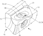
Fig. 3 A is the exploded view according to the cutting tip of the cutting element of the embodiment of the invention;
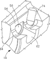
Fig. 3 B is the perspective view according to the cutting tip of Fig. 3 A according to some embodiments of the invention;
Fig. 3 C is the perspective view of the cutting tip among Fig. 3 A, comprises bite spare and sleeve, and wherein bite spare and sleeve are partly cut away;
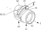
Fig. 4 is the perspective view according to the sleeve of the cutting tip among Fig. 3 A-C of the embodiment of the invention;
Fig. 5 A is the perspective view of the cutting tip of cutting element according to other embodiments of the present invention;
Fig. 5 B is the exploded view of the cutting tip among Fig. 5 A of some other embodiment according to the present invention;
Fig. 6 is the perspective view according to the cutter spare recess of the embodiment of the invention;
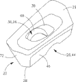
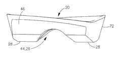
Fig. 7 A is the perspective view according to the bite spare of the embodiment of the invention;
Fig. 7 B is the side view of the bite spare among Fig. 7 A;
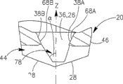
Fig. 7 C is the top view of the bite spare among Fig. 7 A; And
Fig. 7 D is the sectional view of the bite spare among Fig. 7 A of A-A along the line intercepting.
Will be appreciated that for the sake of simplicity and the purpose of signal clearly that element illustrated in the accompanying drawings is unnecessary to be drawn in proportion.For example, for the sake of clarity, the size of some elements can be amplified with respect to other element, perhaps can comprise several physical units in a functional block or element.In addition, in situation about seeing fit, but repeat reference numerals in the accompanying drawings, to indicate correspondence or like.
The specific embodiment
In following description, various aspects of the present invention will be described.For illustrative purposes, set forth concrete configuration and details, in order to provide for thorough understanding of the present invention.Yet, also should it is evident that for those skilled in the art, in the situation that does not depart from detail shown in this article, can implement the present invention.In addition, known features can be economized except or be simplified so that so that the present invention be easily understood.
Although some accompanying drawings herein show rotary cutting tool (for example, grinding tool), the present invention is not limited to this aspect.For example, some embodiments of the present invention can relate to other cutting element that maintains therein one or more releasable bite spares, and described cutting element comprises such as grinding tool, cutting tool or has the one or more any metal-cutting machine tools that discharge bite spare that keep therein.
Referring now to Fig. 1 and Fig. 2, show cutting element 10 according to some embodiments of the invention.Cutting element 10 has front end 12, rear end 14 and rotation R.Cutting element 10 comprises one or more cutting tips 16, and wherein each cutting tip 16 comprises cutter spare recess 18, keeps releasedly therein bite spare 20.
In certain embodiments, bite spare 20 is positioned in the cutter spare recess 18, and for example bite spare 20 is contained on the screwing element 22, with in abutting connection with its top area 24.In this position, the ledge 34 that will be described in more detail below and/or the other parts of screwing element 22 are inserted in respectively in one or more complementary shape parts of the groove 26 that forms at least basal surface 28 of bite spare 20, for example will be described in more detail below.This tangential clamping allows the more finer pitch of cutting element 10,, allows the relative tight spacing of the bite spare 20 in cutting element 10 that is.For example, cutting element 10 can have ten bite spares 20, is when having the grinding tool of 80 mm dias at cutting element 10 for example; Perhaps can have 13 bite spares 20, for example when cutting element 10 has 100 millimeters diameter.
In some non-limiting examples, and as will be described in more detail below, for example with reference to Fig. 3 A-4, screwing element 22 for example comprises differential screw 30 and sleeve 32(mounted thereto, as shown in Figure 3A), sleeve 32 has the ledge 34 in the forming hole 36 that is inserted into groove 26.After fastening differential screw 30, ledge 34 is held in the inner surface 38 one of two of abutting to that bite spare 20 forms by forming hole 36.By this bite spare 20 is clamped in the cutter spare recess 18 in abutting connection with inner surface 38.
In other non-limiting example, for example with reference to Fig. 5 A-5B, screwing element 22 comprises other parts alternatively, and for example clamp screws 40.After being positioned at bite spare 20 in the cutter spare recess 18, the part of the head of screw 42 of clamp screws 40 is inserted in the groove 26, so that thread head 42 is in abutting connection with inner surface.Therefore, when clamp screws 40 was fastened, it was clamped in bite spare 20 in the cutter spare recess 18, as will be described in more detail below.
In certain embodiments, the replacing of bite spare 20 or displacement (indexing) can comprise that the progression for example unscrewing or partly open screwing element 22 is to the predetermined extent of restriction, its permission removes bite spare 20 and/or be inserted into the cutter spare recess 18 from cutter spare recess 18, and does not need to remove screwing element 22 fully from cutter spare recess 18.Therefore, for example, changing bite spare 20 can be performed within the relatively short time period by relatively little power by this.
Referring now to Fig. 3 A-4, it shows cutting tip 16 according to some embodiments of the invention; With reference to Fig. 5 A and Fig. 5 B, it shows cutting tip 16 according to other embodiments of the present invention; And with reference to Fig. 6 and Fig. 7 A, it shows respectively according to the cutter spare recess 18 of the embodiment of the invention and the perspective view of bite spare 20.
For the clear purpose of describing, in Fig. 3 A, introduce and signal right-handed Cartesian coordinate system system.This coordinate system refers to the description of following Fig. 3 A-7A.In this coordinate system, X-axis is defined as the side direction mid-plane M perpendicular to bite spare 20, is described in more detail and defines hereinafter side direction mid-plane M with reference to Fig. 7 B-7D.The forward of X-axis be defined within roughly front end 12 to the rear end 14 ' direction.The Y-axis of coordinate system is defined as the vertical mid-plane L perpendicular to bite spare 20, illustrates in more detail with reference to Fig. 7 A hereinafter and defines vertical mid-plane L.The forward of Y-axis is defined within roughly inwardly radial direction.The forward of Z axis is finished the right-handed Cartesian coordinate system system with X-axis forward and Y-axis forward.Shown in Fig. 7 C and Fig. 7 D, the first inner surface 38A comprises relevant the first neighboring region 68A, and described the first neighboring region 68A at least roughly is positioned on the first side of vertical mid-plane L and has relevant major side surface 46A.Simultaneously, the second inner surface 38B comprises relevant the second neighboring region 68B, and described the second neighboring region 68B is located substantially at least on the second relative side of vertical mid-plane L and also has relevant relative major side surface 46B.Equally as shown in these figures, the first and second neighboring region 68A, 68B are towards relative direction and each other across the non-adjacent area 69A, the 69B that exist in forming hole 36.
In certain embodiments, one or more parts of groove 26 suitable one or more parts of receiving screwing element 22 respectively.For example, the groove 44 of groove 26 can be at least basal surface 28 formation and extension between two relative major side surface 46.The top area 24 of the base portion part 48 of groove and screwing element 22 complementally is shaped and suitable being contained in this top area 24.Similarly, the forming hole 36 of groove 26 can be fitted therein and be received from the ledge 34 of sleeve 32 extensions or the head of screw 42 of clamp screws 40, as will be described in more detail below.
In certain embodiments, the major side wall 54 of cutter spare recess 18 comprises screwed hole 56, to allow receiving therein screw 30.Screw 30 can be differential screw 30 and have the first screw thread 58 and the second screw thread 60 that for example has the opposite threads rotation direction, to allow to receive respectively simultaneously the first screw thread 58 and the second screw thread 60 in screwed hole 56 and internal thread 50.Therefore, fastening or unscrew screw 30 and can be respectively sleeve 32 and major side wall 54 are furthered or be pulled away from, because sleeve 32 slides along the longitudinal axis (being referred to herein as the S axis) of screw 30.In certain embodiments, the S axis can be positioned on the X-Y plane that is limited by X-axis and Y-axis, and can have the direction that limits towards sleeve 32 from screwed hole 56.Forward S axis can form the obtuse angle with the forward X-axis, as will be described in detail below.
Sleeve 32 slides along the with groove part 62 that forms in the base wall 64 of cutter spare recess 18, with the suitable bottom section 66 of receiving screwing element 22 therein.In certain embodiments, for example with reference to Fig. 3 A, with groove part 62 is suitable receives the bottom section 66 of sleeve 32.In other embodiments, for example with reference to Fig. 5 A, with groove part 62 is suitable receives the base section of clamp screws 40, and it carries out the function of screw 30 and sleeve 32 basically.With groove part 62 roughly can have the semicircular cylinder shape, and it has the longitudinal axis with the S dead in line; The shape that perhaps can have a cylinder part perhaps has and the bottom section 66 of screwing element 22 complementary other convenient shape in shape, slides therein to allow screwing element 22.
Be positioned at bite spare 20 in the cutter spare recess 18 and after the trip bolt 30, surfaces for attachment 52 is along neighboring region 68 in abutting connection with inner surface 38, described neighboring region in abutting connection with subregion (for example can comprise two or more differences, two in abutting connection with subregion), the continuous abutment surface that perhaps can be included and extend between surface 38 and the surfaces for attachment 52.
Similarly, in some other embodiment, clamp screws 40 is received in the screwed hole 56 and has the head of screw 42 of the function of basically carrying out ledge 34.Head of screw 42 is inserted in the forming hole 36 after bite spare 20 being navigated in the cutter spare recess 18, and has the lower face 70 in abutting connection with inner surface, and it carries out the function of surfaces for attachment 52 basically.
As will be described in more detail below, geometry and the position of the corresponding component of the geometry of the mid-plane of groove 26 and direction coupling screwing element 22, to allow two or more middle in abutting connection with surfaces for attachment 52 and an inner surface 38 at neighboring region 68, to allow bite spare 20 fixed clamp in cutter spare recess 18.
For example in certain embodiments, surfaces for attachment 52 be general planar or be alternatively depression or have any convenient shape, for example with at described at least two different neighboring regions 68 in abutting connection with inner surface 38.In certain embodiments, inner surface 38 is smooth and surfaces for attachment 52 caves in a little, and perhaps vice versa, to allow by this adjacency between two different different neighboring regions 68 therebetween.
In other embodiments, surfaces for attachment 52 and inner surface 38 are smooth, and therefore abut against the continuous part top of neighboring region 68, namely abut against whole abutment surface top.Other embodiment can comprise other convenient scheme, to form described at least two different neighboring regions 68 between surfaces for attachment 52 and the inner surface.
Owing to the fastening of screw 30 and owing to institute's externally applied forces during operation cutting element 10, inner surface 38 and surfaces for attachment 52 apply power towards each other.Inner surface 38 and surfaces for attachment 52 adjacency in two or more neighboring regions 68 for example allows applied force to distribute between described two or more neighboring regions 68, and reduces by this pressure on neighboring region 68.Therefore, inner surface 38 and surfaces for attachment 52 are durable to apply thereon relative large power with tolerance.
Be positioned at bite spare 10 in the cutter spare recess 18 and after the trip bolt 30, surfaces for attachment 52 promotes inner surface and therefore promotes bite spare 20 integrally against cutter spare recess 18, thereby a plurality of surfaces of clamping bite spare 20 on a plurality of respective wall of cutter spare recess 18, as will be described in more detail below.Similarly, with reference to Fig. 5 A, and after fastening clamp screw 40, lower face 70 is in abutting connection with inner surface 38 and promote inner surface 38 and therefore promote bite spare 20 integrally against a plurality of walls of cutter spare recess 18, with clamping bite spare 20 securely therein.
In certain embodiments, the separately longitudinal axis of clamp screws 40, screwed hole 56 and with groove part 62 is referred to herein as the T axis along common axis T() coaxially alignment, described T axis has the direction that limits towards head of screw 42 from screwed hole 56.Forward T axis can form acute angle with the forward z axis.In addition, the projection of T axis in X-Y plane can with the S dead in line.Therefore, after fastening clamp screw 40, lower face 70 promotes bite spare 20 downwards and inwardly, being about to basal surface 28, major side surface 46 and inferior side surface 72 promotes against diapire 64, major side wall 54 and the inferior sidewall 74 of cutter spare recess 18 respectively, so that bite spare 20 is fastened firmly in the cutter spare recess 18, as will be hereinafter with reference to other embodiment in greater detail.
In certain embodiments, screwed hole 56, internal thread 50 and screw 30 longitudinal axis separately can coaxially align with the S axis and overlap.Surfaces for attachment 52 can form sharp angle α with negative S axis when having flat shape.For example, sharp angle α can be about 75 degree or about 72 degree or be not more than 80 degree or other convenient acute angles.In addition, positive S axis can form obtuse angles beta with positive X-axis.For example, obtuse angles beta can be about 97.5 degree or about 102 degree or be not more than 90 degree or other convenient angles.
Be positioned at bite spare 20 in the cutter spare recess 18 and during trip bolt 30, applying fastening force, thereby bite spare 20 is fixed in the cutter spare recess 18.Because the geometry of cutting tip 16, more specifically since form between surfaces for attachment 52 and the negative S axis sharp angle α and since positive S axis with just forming obtuse angles beta between the X-axis, this fastening force has and is in the component of bearing S axis direction and negative Z-direction.
Therefore, the force component of fastening force inwardly and downwards promotes bite spare 20 against a plurality of walls of cutter spare recess 18, with clamping bite spare 20 securely therein.For example, the force component of fastening force respectively against major side wall 54, inferior sidewall 74 and diapire 64, and thereby is firmly fastened to bite spare 20 major side surface 46, inferior side surface 72 and basal surface 28 and be positioned in the cutter spare recess 18.Therefore, bite spare 20 keeps securely clamping and is positioned in the cutter spare recess 18, for example can tolerate during cutting operation and apply external force thereon.
Referring now to Fig. 7 B-7D, it shows the some views according to the bite spare 20 of the embodiment of the invention.Vertical mid-plane L of bite spare 20 is defined as the mid-plane of the bite spare 20 that extends through the longitudinal axis of bite spare 20 and be roughly parallel to major side surface 46.The side direction mid-plane M of bite spare 20 is defined as the mid-plane of the bite spare 20 that extends through the lateral axes of bite spare 20 and be approximately perpendicular to major side surface 46.
As mentioned above, in certain embodiments, groove 26 is suitable one or more parts of receiving screwing element 22 securely therein.In certain embodiments, such as, but be not limited to this aspect, groove 26 comprises groove 44, and the groove 44 therein suitable at least zone of receiving the base portion part, for example at least top area 24 of base portion part.Therefore in other embodiments, groove 26 only comprises forming hole 36, and ledge 34 is fitted unique part of the screwing element 22 that is contained in the groove 26.
For example in certain embodiments, groove 44 can be positioned substantially in the zone line 78 of basal surface 28.Groove 44 can be between two major side surface 46 longitudinal extension, and have the longitudinal axis that is referred to herein as the G axis.The G axis can with the S dead in line.Groove 44 can have roughly semicircular cylinder shape, the perhaps shape of a cylinder part.In certain embodiments, groove 44 can have elliptic cross-section, perhaps has the arch cross section.Alternatively, groove 44 can have other convenient shape, with the suitable top area 24 of receiving screwing element 22 securely therein, and the suitable top area 24 of receiving sleeve 32 therein for example.
The geometry of bite spare 20, more specifically groove 44 form and therein the suitable of base portion part 48 receive, allow height h relatively little and still allow surfaces for attachment 52 that bite spare 20 is clamped in the cutter spare recess 18 securely.This can cause ledge 34 relatively durable, namely can tolerate relatively large power and can not break and can not cause failing with bite spare 20 securely clamping put in place.For example this be because, because height h is relatively little, even the very large power on the ledge 34 of being applied to can cause applying the moment of torsion of thereon relatively little.For example in certain embodiments, height h can be less than the thickness of bite spare 20, for example can less than bite spare 20 thickness half or approximately be bite spare 20 thickness 45% or be not more than 40% etc. of bite spare 20 thickness.
For example, in certain embodiments, forming hole 36 extends between top surface 29 at the basically zone line 78 of basal surface 28.Forming hole 36 extends on the top surface 29 and opens to this top surface, and therefore forms the hole in top surface 29.This can be conducive to make bite spare 20.In other embodiments, forming hole 36 extends towards top surface 29 from basal surface 28, and limited by top surface, and therefore keeps top surface puncherless.
In certain embodiments, forming hole has the non-cylinder horizontal cross-section.In certain embodiments, perpendicular to side direction and vertically mid-plane M and L, described cross section can have the elongated shape of extending on the elongation axis that is referred to herein as the E axis respectively in the cross section of forming hole 36.The E axis is transverse to the S axis.In certain embodiments, in the top view of bite spare 20, forming hole 36 has along the elongated shape of E Axis Extension.
In in certain embodiments (for example, wherein inner surface 38 is plane), two inner surfaces 38 each can form with vertical mid-plane of forming hole 36 acute angle of non-zero angle, for example sharp angle α.In addition, thus the intersection of the side direction mid-plane of forming hole 36 and its horizontal cross-section can be parallel to the S axis or with the S dead in line.This allows the match surface adjacency between adjacency inner surface 38 and surfaces for attachment 52, and allows by this to mate bite spare 20 and be clamped in securely and mate in the cutter spare recess 18, as mentioned above.In other embodiments, can be formed on the coupling bite spare 20 each section between other convenient angle.
Yet in all previous embodiment, groove 26 is shaped to receive screwing element 22 via basal surface 28, is used for applying fastening force against at least one neighboring region.
Although the present invention is described with reference to one or more specific embodiments, this explanation is intended to schematically and the embodiment shown in should being considered to not limit the invention to generally.Though it being understood that but those skilled in the art can expect not specifically illustrating the various modifications that fall in the scope of the invention at this paper.
Claims (14)
1. an one-sided bite spare (20) comprising:
Basal surface (28);
Top surface (29);
Two relative major side surface (46) the inferior side surface (72) relative with two that between top surface and basal surface (29,28), extends;
Vertical mid-plane (L), described vertical mid-plane and described two side surfaces (72) and top surface and basal surface (29,28) intersect;
Side direction mid-plane (M), described side direction mid-plane and described two major side surface (46) and top surface and basal surface (29,28) intersect; And
Be formed on the groove (26) in the basal surface (28), described groove comprises the forming hole (36) that extends towards top surface (29); Wherein:
Forming hole (36) has the first inner surface (38A), and described the first inner surface comprises the first neighboring region (68A) that is positioned at least on vertical mid-plane (L) the first side;
Forming hole (36) has the second inner surface (38B), and described the second inner surface comprises the second neighboring region (68B) that is positioned at least on vertical mid-plane (L) the second side;
The first and second neighboring regions (68A, 68B) are towards relative direction; And
Groove (26) is shaped to receive screwing element (22) via basal surface (28), and at least one that is used for against the first and second neighboring regions (68A, 68B) applies fastening force; And
Wherein, groove (26) comprises groove (44), and described groove extends between described two major side surface (46) and along basal surface (28).
2. one-sided bite spare according to claim 1 (20), wherein:
The first and second neighboring regions (68A, 68B) are each other across the non-adjacent area (69A, 69B) that exists in forming hole (36).
3. one-sided bite spare according to claim 1 (20), wherein:
From the side view of bite spare (20), groove (44) has arcuate in shape.
4. one-sided bite spare according to claim 1 (20), wherein:
Forming hole (36) is opened to top surface (29), forms by this hole in top surface (29).
5. one-sided bite spare according to claim 1 (20), wherein:
In the top view of bite spare (20), forming hole (36) has the elongated shape of extending along elongating axis (E).
6. one-sided bite spare according to claim 5 (20), wherein:
The elongation axis (E) of forming hole (36) and vertical mid-plane (L) form the acute angle (α) of the first non-zero.
7. one-sided bite spare according to claim 1 (20), wherein:
Groove (26) disposes and is sized to the suitable ledge (34) of receiving screwing element (22), is used in abutting connection with the first and second neighboring regions one of the surfaces for attachment (52) of ledge (34).
8. cutting element (10) with at least one cutting tip (16), described at least one cutting tip (16) comprising:
Cutter spare recess (18), described cutter spare recess have the major side wall (54) that is provided with screwed hole (56);
Bite spare (20), described bite spare comprises basal surface (28), top surface (29), at top surface and basal surface (29, the inferior side surface (72) that two relative major side surface (46) of extending 28) are relative with two and be formed on groove (26) in the basal surface (28), described groove comprises the forming hole (36) that extends towards top surface (29), wherein:
Forming hole (36) has the first inner surface (38A), described the first inner surface comprises the first neighboring region (68A) that is positioned at least on vertical mid-plane (L) the first side, vertically mid-plane (L) and two side surfaces (72) and top surface and basal surface (29,28) intersect;
Forming hole (36) has the second inner surface (38B), and described the second inner surface comprises the second neighboring region (68B) that is positioned at least on vertical mid-plane (L) the second side;
The first and second neighboring regions (68A, 68B) are towards relative direction; And
Groove (26) comprises groove (44), described groove extends between two major side surface (46) and along basal surface (28), described groove (44) is shaped to receive screwing element (22) via basal surface (28), so that bite spare (20) is remained in the cutter spare recess (18) releasedly, described screwing element (22) comprises surfaces for attachment (52), described surfaces for attachment is at least one adjacency in the first and second neighboring regions (68A, 68B) and apply fastening force.
9. cutting element according to claim 8 (10), wherein:
The with groove part (62) that cutter spare recess (18) also comprises diapire (64) and forms in diapire (64); And
The bottom section of screwing element (22) is fitted in the with groove part (62) that is contained in cutter spare recess (18).
10. cutting element according to claim 8 (10), wherein:
Screwing element (22) comprises clamp screws (40), and described clamp screws has head of screw (42);
Clamp screws (40) is received in the screwed hole (56) of cutter spare recess (18); And
Head of screw (42) has lower face (70), described lower face as surfaces for attachment (52) and with the first and second neighboring regions (68A, 68B) at least one adjacency.
11. cutting element according to claim 8 (10), wherein:
Screwing element (22) comprises sleeve (32) and the screw with internal thread;
Sleeve (32) is installed on the screw; And
Surfaces for attachment (52) is arranged on the sleeve (32).
12. cutting element according to claim 8 (10), wherein:
Screw comprises differential screw (30), described differential screw comprises the first and second screw threads (58 with different thread rotary orientations, 60), receive in the internal thread (50) to allow simultaneously the first screw thread (58) to be received in the screwed hole (56) and with the second screw thread (60).
13. cutting element according to claim 8 (10), wherein:
Screwing element (22) comprising:
Base portion part (48), but described base portion partly is received in the screwed hole (56) of cutter spare recess (18) to the quilt turn; And
Ledge (34), described ledge extend in the groove (26) of bite spare (20), and surfaces for attachment (52) is formed on the ledge (34).
14. cutting element according to claim 13 (10), wherein:
Ledge (34) has and is no more than half height of bite spare (20) thickness.
Applications Claiming Priority (3)
| Application Number | Priority Date | Filing Date | Title |
|---|---|---|---|
| IL194924 | 2008-10-26 | ||
| IL194924A IL194924A (en) | 2008-10-26 | 2008-10-26 | Cutting tool and cutting insert therefor |
| PCT/IL2009/000979 WO2010046892A1 (en) | 2008-10-26 | 2009-10-15 | Cutting tool and cutting insert therefor |
Publications (2)
| Publication Number | Publication Date |
|---|---|
| CN102196875A CN102196875A (en) | 2011-09-21 |
| CN102196875B true CN102196875B (en) | 2013-03-13 |
Family
ID=41571530
Family Applications (1)
| Application Number | Title | Priority Date | Filing Date |
|---|---|---|---|
| CN2009801423848A Expired - Fee Related CN102196875B (en) | 2008-10-26 | 2009-10-15 | Cutting tool and cutting insert therefor |
Country Status (13)
| Country | Link |
|---|---|
| US (1) | US8356960B2 (en) |
| EP (1) | EP2342034B1 (en) |
| JP (1) | JP2012506778A (en) |
| KR (1) | KR101586521B1 (en) |
| CN (1) | CN102196875B (en) |
| BR (1) | BRPI0919900A2 (en) |
| ES (1) | ES2547540T3 (en) |
| IL (1) | IL194924A (en) |
| PL (1) | PL2342034T3 (en) |
| PT (1) | PT2342034E (en) |
| RU (1) | RU2500507C2 (en) |
| TW (1) | TW201020043A (en) |
| WO (1) | WO2010046892A1 (en) |
Families Citing this family (15)
| Publication number | Priority date | Publication date | Assignee | Title |
|---|---|---|---|---|
| EP2167260B1 (en) * | 2007-06-06 | 2013-06-05 | No Screw Ltd. | A cutting tool holder and method for mounting a cutting insert on such a holder |
| IL185048A (en) * | 2007-08-05 | 2011-07-31 | Iscar Ltd | Cutting tool and cutting insert therefor |
| IL211326A (en) * | 2011-02-21 | 2014-07-31 | Iscar Ltd | Cutting tool and cutting insert therefor |
| PL2739421T3 (en) | 2011-08-02 | 2019-10-31 | Iscar Ltd | Cutting tool and cutting insert |
| US9475131B2 (en) * | 2013-06-13 | 2016-10-25 | Kennametal Inc. | Milling cutter with stress reliefs |
| US9103418B2 (en) * | 2013-07-01 | 2015-08-11 | Iscar, Ltd. | Machine tool assembly for machining workpieces and actuator component thereof |
| US9505066B2 (en) * | 2014-08-01 | 2016-11-29 | Kennametal Inc. | Rotary cutting tool with regrindable cutting inserts |
| US10010942B2 (en) * | 2016-06-20 | 2018-07-03 | Iscar, Ltd. | Cutting tool and cutting insert having a deep blind opening |
| US11235397B2 (en) | 2016-12-16 | 2022-02-01 | Kennametal Inc. | Side-activated modular drill |
| US10207337B2 (en) | 2017-04-04 | 2019-02-19 | Kennametal Inc. | Front-loaded, side-activated modular drill |
| DE102019116160A1 (en) | 2018-06-20 | 2019-12-24 | Kennametal Inc. | Modular drill bit closed on the side with spring-assisted ejection |
| US11090736B2 (en) | 2018-12-10 | 2021-08-17 | Kennametal Inc. | Side-activated modular drill |
| US11453065B2 (en) * | 2019-05-24 | 2022-09-27 | Iscar, Ltd. | Cutting insert having lower anti-slip recess, insert holder and cutting tool |
| US11471952B2 (en) | 2020-03-19 | 2022-10-18 | Kennametal Inc. | Cutting tool having replaceable cutting head and method of securing a replaceable cutting head |
| US11883888B2 (en) | 2021-06-28 | 2024-01-30 | Kennametal Inc. | Modular drill with enhanced bump-off capability |
Citations (1)
| Publication number | Priority date | Publication date | Assignee | Title |
|---|---|---|---|---|
| EP1736263A1 (en) * | 2004-03-26 | 2006-12-27 | Mitsubishi Materials Corporation | Clamping structure for throwaway chip |
Family Cites Families (19)
| Publication number | Priority date | Publication date | Assignee | Title |
|---|---|---|---|---|
| SU593838A1 (en) * | 1973-01-08 | 1978-02-25 | Горьковский Завод Фрезерных Станков | Face-milling cutter |
| DE2741130A1 (en) * | 1977-09-13 | 1979-03-15 | Mapal Fab Praezision | CUTTING TOOL WITH ADJUSTABLE INSERT |
| DE3405211A1 (en) * | 1984-02-14 | 1985-08-14 | Walter Kieninger GmbH, 7630 Lahr | Cutting tool for machining |
| SE504205C2 (en) * | 1994-04-27 | 1996-12-09 | Sandvik Ab | Cut with grooves |
| SE505726C2 (en) * | 1995-02-27 | 1997-10-06 | Sandvik Ab | Clamping device for cutting plates |
| JPH1119808A (en) * | 1997-06-30 | 1999-01-26 | Ngk Spark Plug Co Ltd | Cutting chip and cutting tool using therewith |
| SE514032C2 (en) * | 1998-09-08 | 2000-12-11 | Seco Tools Ab | Tools and cutters for milling |
| JP2000254806A (en) | 1999-03-08 | 2000-09-19 | Toshiba Tungaloy Co Ltd | Throw away type cutting tool's clamp structure |
| SE520997C2 (en) | 2001-01-09 | 2003-09-23 | Sandvik Ab | Reversible cutter with grooved coupling surface against the holder and central material portion for fasteners |
| SE520628C2 (en) * | 2001-01-09 | 2003-08-05 | Sandvik Ab | Tools and cutting body for chip separating machining where the coupling surfaces have matching grooves and ridges |
| IL144154A0 (en) * | 2001-07-05 | 2002-05-23 | Iscar Ltd | Cutting tool and cutting insert therefor |
| US6960049B2 (en) * | 2002-06-25 | 2005-11-01 | Ngk Spark Plug Co., Ltd. | Insert, holder and cutting tool |
| US7144205B2 (en) * | 2003-05-09 | 2006-12-05 | Kennametal Inc. | Insert retention screw and tool body and insert therewith |
| SE527851C2 (en) * | 2004-02-11 | 2006-06-20 | Sandvik Intellectual Property | Cutting tools, cutting tools and parts for cutting tools with serration coupling surfaces |
| JP4364683B2 (en) | 2004-03-16 | 2009-11-18 | 株式会社タンガロイ | Throw-away cutting tool |
| GB0406664D0 (en) * | 2004-03-24 | 2004-04-28 | Samsung Electronics Co Ltd | Mobile communications |
| SE527543C2 (en) * | 2004-08-30 | 2006-04-04 | Sandvik Intellectual Property | Cutting position with grooved support surface |
| US7347650B2 (en) * | 2005-10-17 | 2008-03-25 | Vichente Tipu | Cutting tool with locking pin |
| RU2318635C1 (en) * | 2006-08-07 | 2008-03-10 | Нина Алексеевна Корюкина | Built-up milling cutter |
-
2008
- 2008-10-26 IL IL194924A patent/IL194924A/en not_active IP Right Cessation
- 2008-11-17 TW TW097144404A patent/TW201020043A/en unknown
-
2009
- 2009-10-15 ES ES09760619.8T patent/ES2547540T3/en active Active
- 2009-10-15 JP JP2011532767A patent/JP2012506778A/en active Pending
- 2009-10-15 KR KR1020117009381A patent/KR101586521B1/en active IP Right Grant
- 2009-10-15 PL PL09760619T patent/PL2342034T3/en unknown
- 2009-10-15 RU RU2011121141/02A patent/RU2500507C2/en not_active IP Right Cessation
- 2009-10-15 PT PT97606198T patent/PT2342034E/en unknown
- 2009-10-15 WO PCT/IL2009/000979 patent/WO2010046892A1/en active Application Filing
- 2009-10-15 EP EP09760619.8A patent/EP2342034B1/en not_active Not-in-force
- 2009-10-15 BR BRPI0919900A patent/BRPI0919900A2/en not_active IP Right Cessation
- 2009-10-15 CN CN2009801423848A patent/CN102196875B/en not_active Expired - Fee Related
- 2009-10-15 US US12/579,466 patent/US8356960B2/en not_active Expired - Fee Related
Patent Citations (1)
| Publication number | Priority date | Publication date | Assignee | Title |
|---|---|---|---|---|
| EP1736263A1 (en) * | 2004-03-26 | 2006-12-27 | Mitsubishi Materials Corporation | Clamping structure for throwaway chip |
Non-Patent Citations (2)
| Title |
|---|
| JP特开2000-254806A 2000.09.19 |
| JP特开2005-262329A 2005.09.29 |
Also Published As
| Publication number | Publication date |
|---|---|
| PT2342034E (en) | 2015-11-20 |
| ES2547540T3 (en) | 2015-10-07 |
| CN102196875A (en) | 2011-09-21 |
| TW201020043A (en) | 2010-06-01 |
| RU2011121141A (en) | 2012-12-10 |
| WO2010046892A1 (en) | 2010-04-29 |
| KR20110082144A (en) | 2011-07-18 |
| JP2012506778A (en) | 2012-03-22 |
| KR101586521B1 (en) | 2016-01-18 |
| BRPI0919900A2 (en) | 2016-02-16 |
| EP2342034B1 (en) | 2015-09-16 |
| RU2500507C2 (en) | 2013-12-10 |
| PL2342034T3 (en) | 2016-01-29 |
| IL194924A0 (en) | 2009-08-03 |
| EP2342034A1 (en) | 2011-07-13 |
| US8356960B2 (en) | 2013-01-22 |
| IL194924A (en) | 2013-02-28 |
| US20100104384A1 (en) | 2010-04-29 |
Similar Documents
| Publication | Publication Date | Title |
|---|---|---|
| CN102196875B (en) | Cutting tool and cutting insert therefor | |
| JP5451771B2 (en) | Cutting tool clamp mechanism | |
| US8727674B2 (en) | Tool holder with nubs for clamping a cutting insert with notches | |
| EP2945765B1 (en) | Cutting tool with cutting insert having non-abutting side flanks | |
| CN101204738B (en) | A turning tool as well as a turning insert | |
| CN102341203B (en) | Cutting inset and detachable cutting tool for cutting insert | |
| RU2121905C1 (en) | Apparatus for mounting cutting tip in holders at cutting | |
| KR100824245B1 (en) | Tool for chip-removing machining | |
| CN102239022B (en) | Tool holder for clamping an insert holder | |
| CN106488835B (en) | Tool head and method for inserting and clamping an insert, and insert | |
| CN108687385B (en) | Front loading, side activated modular drill bit | |
| EP2498937B1 (en) | Cutting tool assembly | |
| CN101543906A (en) | Insert clamping wedge and insert-detachable type cutter | |
| JP5800111B2 (en) | Cutting tool mounting device, tool body and cutting tool | |
| EP1287929A2 (en) | Tool for chip removing machining | |
| US20210379679A1 (en) | Cutting tool | |
| KR20040018408A (en) | Cutting tool with edge-on mounted inserts | |
| US20140178137A1 (en) | Tool holder with nubs for clamping a cutting insert with notches | |
| WO2022181773A1 (en) | Clamp structure of cutting insert, and cutting-edge replaceable cutting tool | |
| KR100977695B1 (en) | Cutting tool head for a metalworking tool | |
| JP2022130329A (en) | Clamp structure of cutting insert and cutting tool with replaceable blade edge | |
| JP2023120999A (en) | Cutting insert clamp structure and edge replaceable cutting tool | |
| JP2006123042A (en) | Cutting head changing type cutting tool |
Legal Events
| Date | Code | Title | Description |
|---|---|---|---|
| C06 | Publication | ||
| PB01 | Publication | ||
| C10 | Entry into substantive examination | ||
| SE01 | Entry into force of request for substantive examination | ||
| C14 | Grant of patent or utility model | ||
| GR01 | Patent grant | ||
| CF01 | Termination of patent right due to non-payment of annual fee |
Granted publication date: 20130313 Termination date: 20191015 |
|
| CF01 | Termination of patent right due to non-payment of annual fee |