JP5800111B2 - Cutting tool mounting device, tool body and cutting tool - Google Patents
Cutting tool mounting device, tool body and cutting tool Download PDFInfo
- Publication number
- JP5800111B2 JP5800111B2 JP2015515751A JP2015515751A JP5800111B2 JP 5800111 B2 JP5800111 B2 JP 5800111B2 JP 2015515751 A JP2015515751 A JP 2015515751A JP 2015515751 A JP2015515751 A JP 2015515751A JP 5800111 B2 JP5800111 B2 JP 5800111B2
- Authority
- JP
- Japan
- Prior art keywords
- wall surface
- side wall
- insert
- cutting
- cutting insert
- Prior art date
- Legal status (The legal status is an assumption and is not a legal conclusion. Google has not performed a legal analysis and makes no representation as to the accuracy of the status listed.)
- Active
Links
Images


Classifications
-
- B—PERFORMING OPERATIONS; TRANSPORTING
- B23—MACHINE TOOLS; METAL-WORKING NOT OTHERWISE PROVIDED FOR
- B23B—TURNING; BORING
- B23B27/00—Tools for turning or boring machines; Tools of a similar kind in general; Accessories therefor
- B23B27/14—Cutting tools of which the bits or tips or cutting inserts are of special material
- B23B27/16—Cutting tools of which the bits or tips or cutting inserts are of special material with exchangeable cutting bits or cutting inserts, e.g. able to be clamped
- B23B27/1662—Cutting tools of which the bits or tips or cutting inserts are of special material with exchangeable cutting bits or cutting inserts, e.g. able to be clamped with plate-like cutting inserts clamped against the walls of the recess in the shank by a clamping member acting upon the wall of a hole in the cutting insert
-
- B—PERFORMING OPERATIONS; TRANSPORTING
- B23—MACHINE TOOLS; METAL-WORKING NOT OTHERWISE PROVIDED FOR
- B23C—MILLING
- B23C5/00—Milling-cutters
- B23C5/02—Milling-cutters characterised by the shape of the cutter
- B23C5/10—Shank-type cutters, i.e. with an integral shaft
- B23C5/109—Shank-type cutters, i.e. with an integral shaft with removable cutting inserts
-
- B—PERFORMING OPERATIONS; TRANSPORTING
- B23—MACHINE TOOLS; METAL-WORKING NOT OTHERWISE PROVIDED FOR
- B23C—MILLING
- B23C5/00—Milling-cutters
- B23C5/16—Milling-cutters characterised by physical features other than shape
- B23C5/20—Milling-cutters characterised by physical features other than shape with removable cutter bits or teeth or cutting inserts
- B23C5/22—Securing arrangements for bits or teeth or cutting inserts
- B23C5/2204—Securing arrangements for bits or teeth or cutting inserts with cutting inserts clamped against the walls of the recess in the cutter body by a clamping member acting upon the wall of a hole in the insert
- B23C5/2208—Securing arrangements for bits or teeth or cutting inserts with cutting inserts clamped against the walls of the recess in the cutter body by a clamping member acting upon the wall of a hole in the insert for plate-like cutting inserts
-
- B—PERFORMING OPERATIONS; TRANSPORTING
- B23—MACHINE TOOLS; METAL-WORKING NOT OTHERWISE PROVIDED FOR
- B23B—TURNING; BORING
- B23B2205/00—Fixation of cutting inserts in holders
- B23B2205/04—Fixation screws, bolts or pins of particular form
- B23B2205/045—Fixation screws, bolts or pins of particular form orientated obliquely to the hole in the insert or to the seating surface
-
- B—PERFORMING OPERATIONS; TRANSPORTING
- B23—MACHINE TOOLS; METAL-WORKING NOT OTHERWISE PROVIDED FOR
- B23C—MILLING
- B23C2210/00—Details of milling cutters
- B23C2210/16—Fixation of inserts or cutting bits in the tool
- B23C2210/168—Seats for cutting inserts, supports for replacable cutting bits
-
- Y—GENERAL TAGGING OF NEW TECHNOLOGICAL DEVELOPMENTS; GENERAL TAGGING OF CROSS-SECTIONAL TECHNOLOGIES SPANNING OVER SEVERAL SECTIONS OF THE IPC; TECHNICAL SUBJECTS COVERED BY FORMER USPC CROSS-REFERENCE ART COLLECTIONS [XRACs] AND DIGESTS
- Y10—TECHNICAL SUBJECTS COVERED BY FORMER USPC
- Y10T—TECHNICAL SUBJECTS COVERED BY FORMER US CLASSIFICATION
- Y10T407/00—Cutters, for shaping
- Y10T407/22—Cutters, for shaping including holder having seat for inserted tool
- Y10T407/2272—Cutters, for shaping including holder having seat for inserted tool with separate means to fasten tool to holder
- Y10T407/2274—Apertured tool
- Y10T407/2276—Apertured tool with means projecting through aperture to force tool laterally against reaction surface
Description
本発明は、切削インサートを着脱自在に装着するための切削工具の装着装置、工具ボデー、および切削工具に関する。 The present invention relates to a cutting tool mounting apparatus, a tool body, and a cutting tool for detachably mounting a cutting insert.
締めつけねじを用いて工具ボデーに切削インサートを装着する切削工具の装着装置には、種々のものがある。ここで例示する装着装置は、工具ボデーのインサート取付座に、切削インサートの貫通穴に挿通された締めつけねじが螺合可能なねじ穴を有する装着構造のことを指す。 There are various cutting tool mounting apparatuses for mounting a cutting insert on a tool body using a fastening screw. The mounting device illustrated here refers to a mounting structure having a screw hole into which a fastening screw inserted through a through hole of a cutting insert can be screwed in an insert mounting seat of a tool body.
例えば特許文献1には、底壁面と2つの側壁面とを有するインサート取付座において、締めつけねじを、切削インサートの貫通穴を通して底壁面のねじ穴に螺入させることで、切削インサートが着脱自在に固定される切削工具が開示されている。この切削工具の装着装置では、インサート取付座の底壁面におけるねじ穴の中心軸線は、同底壁面の法線方向に対して傾斜する。特許文献1の記載のようにねじ穴の中心軸線が傾斜すると、締めつけねじを切削インサートの貫通穴を通して底壁面のねじ穴にねじ込むことで、切削インサートをインサート取付座の側壁面側に押しつけることができる。
For example, in
一方、締めつけねじを用いて切削インサートを固定する切削工具の装着装置において、締めつけねじに対応するねじ穴の中心軸線を切削インサートの貫通穴の中心軸線に対してインサート取付座の側壁面側に平行にずらして、ねじ穴を形成した装着装置も知られている。このようにインサート取付座のねじ穴の中心軸線を、切削インサートの貫通穴の中心軸線に対してずらして形成すると、締めつけねじを締めることで、切削インサートをインサート取付座の側壁面側に押しつけることができる。 On the other hand, in a cutting tool mounting apparatus that uses a clamping screw to fix the cutting insert, the center axis of the screw hole corresponding to the clamping screw is parallel to the side wall surface side of the insert mounting seat with respect to the center axis of the through hole of the cutting insert. There is also known a mounting device in which a screw hole is formed by shifting to the above. When the center axis of the screw hole of the insert mounting seat is shifted with respect to the center axis of the through hole of the cutting insert in this way, the cutting insert is pressed against the side wall surface of the insert mounting seat by tightening the tightening screw. Can do.
ねじ穴の中心軸線を切削インサートの貫通穴の中心軸線に対して平行にずらして形成する従来の装着装置を適用した切削工具では、締めつけねじを切削インサートの貫通穴を介してインサート取付座のねじ穴に締め付けることで、締めつけねじにそれを破断しようとする力が加わる。したがって、締めつけねじの寿命が比較的短くなり易い。これに対して、特許文献1の装着装置のように、ねじ穴の中心軸線をインサート取付座の底壁面の法線方向に対して傾斜させることは、締めつけねじの破断を抑制する一定の効果があった。
In a cutting tool to which a conventional mounting device that is formed by shifting the center axis of the screw hole parallel to the center axis of the through hole of the cutting insert, the tightening screw is inserted into the screw of the insert mounting seat through the through hole of the cutting insert. By tightening in the hole, a force is applied to the clamping screw to break it. Therefore, the life of the fastening screw tends to be relatively short. On the other hand, inclining the central axis of the screw hole with respect to the normal direction of the bottom wall surface of the insert mounting seat as in the mounting device of
ところで、近年、例えば難削材の切削加工、高速度切削などに対する需要の高まりから、切削インサートの締めつけ状態をより安定させたいという要望が高まっている。具体的には、締めつけねじを締めつけたときの切削インサートの締付安定性を高めることができると共に、締つけねじの寿命を徒に短くしないような装着装置に対する必要性がある。 By the way, in recent years, for example, demand for cutting of difficult-to-cut materials, high-speed cutting, and the like has increased, and there is an increasing demand for more stable tightening conditions of cutting inserts. Specifically, there is a need for a mounting device that can increase the clamping stability of the cutting insert when the clamping screw is tightened and does not shorten the lifetime of the clamping screw.
本発明は、上記事情に鑑みて創案されたものであり、その目的は、インサート取付座における切削インサートの締めつけ状態をより安定させることにある。 The present invention has been made in view of the above circumstances, and an object thereof is to further stabilize the tightening state of the cutting insert in the insert mounting seat.
本発明の一態様によれば、
切削インサートの貫通穴を通して締めつけねじを工具ボデーのインサート取付座のねじ穴に螺入することで該切削インサートが該インサート取付座に着脱自在に装着される切削工具に適合される装着装置であって、
インサート取付座は、底壁面と、該底壁面に交差するように延在する少なくとも2つの側壁面とを有し、
底壁面には、ねじ穴が交差し、
ねじ穴の中心軸線は、底壁面の法線方向に対して傾斜し、
インサート取付座に切削インサートが載置されたとき、底壁面を拡張するように定められる第1仮想平面上において、ねじ穴の中心軸線の第1通過点は、貫通穴の中心軸線の第2通過点から、少なくとも2つの側壁面のうちの少なくともいずれか一方側にずれていて、
第1仮想平面上においてねじ穴の中心軸線の第1通過点の貫通穴の中心軸線の第2通過点からのずれ方向を芯寄せ方向とし、かつ、第1仮想平面上にねじ穴の中心軸線を投影した仮想線の方向を傾斜方向とすると、
芯寄せ方向と傾斜方向とは異なる方向である、
装着装置が提供される。According to one aspect of the invention,
An attachment device adapted to a cutting tool in which the cutting insert is detachably attached to the insert mounting seat by screwing a tightening screw into a screw hole of the insert mounting seat of the tool body through a through hole of the cutting insert. ,
The insert mounting seat has a bottom wall surface and at least two side wall surfaces extending so as to intersect the bottom wall surface,
Screw holes intersect the bottom wall,
The central axis of the screw hole is inclined with respect to the normal direction of the bottom wall surface,
When the cutting insert is placed on the insert mounting seat, the first passage point of the central axis of the screw hole is the second passage of the central axis of the through hole on the first virtual plane that is defined to expand the bottom wall surface. The point is shifted to at least one of at least two side wall surfaces,
On the first imaginary plane, the shift direction of the center axis of the through hole of the first passage point from the second passage point on the first imaginary plane is the centering direction, and the center axis of the screw hole on the first imaginary plane If the direction of the imaginary line projected is the tilt direction,
The centering direction and the inclination direction are different directions.
A mounting device is provided.
好ましくは、ねじ穴の中心軸線を含み底壁面に略直交するように第2仮想平面を定めるとき、ねじ穴の中心軸線は、該第2仮想平面において少なくとも2つの側壁面側の底壁面の部分とインサート内鋭角をなすように、傾斜している。 Preferably, when the second imaginary plane is defined so as to include the center axis of the screw hole and substantially perpendicular to the bottom wall surface, the center axis of the screw hole is a portion of the bottom wall surface on the side of at least two side wall surfaces in the second imaginary plane. It is inclined so as to form an acute angle in the insert.
好ましくは、第1仮想平面上におけるねじ穴の中心軸線の傾斜方向は、第1通過点から少なくとも2つの側壁面側の方向である。少なくとも2つの側壁面は、主拘束面としての第1の側壁面と、副拘束面としての第2の側壁面とを含むとよい。芯寄せ方向は第1および第2の側壁面のうちで第1の側壁面側を向き、傾斜方向は芯寄せ方向と比較して第1および第2の側壁面のうちで第2の側壁面側寄りであるとよい。第1の側壁面と第2の側壁面とのそれぞれの延長により定められる交差部において、該交差部における交差角度を2等分するように第1の側壁面と第2の側壁面との間に底壁面に略直交するように延びる第3仮想平面を定めることができる。好ましくは、傾斜方向および芯寄せ方向は該第3仮想平面により境界付けられた2つの領域のうちの第1の側壁面側の領域に方向付けられることができる。幾つかの実施形態において、傾斜方向および芯寄せ方向は共に、第1の側壁面と交差するように方向付けられているとよい。第1仮想平面上において、芯寄せ方向の第3仮想平面に対する角度は、20°以上、かつ90°以下の範囲であるとよい。さらに、第1仮想平面上において、傾斜方向と芯寄せ方向との角度差は、1°以上、かつ80°以下の範囲であるとよい。例えば、切削インサートは、略三角形板状である。この場合を含めた幾つかの実施形態において、第1の側壁面と第2の側壁面とのそれぞれの延長により定められる交差部の交差角度は鋭角である。あるいは、その交差角度は鈍角でも、直角でもよい。好ましくは、締めつけねじを切削インサートの貫通穴を通してねじ穴に対してねじ込んだとき、該締めつけねじは、貫通穴を定める面にその実質的に全周で接触するとよい。 Preferably, the direction of inclination of the central axis of the screw hole on the first virtual plane is a direction on the side of at least two side wall surfaces from the first passing point. The at least two side wall surfaces may include a first side wall surface as a main constraining surface and a second side wall surface as a sub constraining surface. The centering direction faces the first side wall surface side of the first and second side wall surfaces, and the tilt direction is the second side wall surface of the first and second side wall surfaces compared to the centering direction. It should be close to the side. At the intersection defined by the respective extensions of the first and second sidewall surfaces, the intersection angle between the first sidewall surface and the second sidewall surface is divided into two equal parts. A third virtual plane extending substantially perpendicular to the bottom wall surface can be defined. Preferably, the tilt direction and the centering direction can be directed to a region on the first side wall surface side of the two regions bounded by the third virtual plane. In some embodiments, both the tilt direction and the centering direction may be oriented to intersect the first sidewall surface. On the first virtual plane, the angle of the centering direction with respect to the third virtual plane is preferably in the range of 20 ° or more and 90 ° or less. Furthermore, on the first virtual plane, the angle difference between the tilt direction and the centering direction is preferably in the range of 1 ° or more and 80 ° or less. For example, the cutting insert has a substantially triangular plate shape. In some embodiments including this case, the intersection angle of the intersection defined by the respective extensions of the first sidewall surface and the second sidewall surface is an acute angle. Alternatively, the intersection angle may be an obtuse angle or a right angle. Preferably, when the tightening screw is screwed into the screw hole through the through hole of the cutting insert, the tightening screw contacts substantially the entire circumference with the surface defining the through hole.
本発明は、上記一態様の装着装置が適用された工具ボデーにも存する。また、本発明は、上記一態様の装着装置が適用された切削工具にも存する。 The present invention also resides in a tool body to which the mounting device of the above aspect is applied. The present invention also resides in a cutting tool to which the mounting device of the above aspect is applied.
本発明の上記一態様によれば、第1仮想平面上における芯寄せ方向と傾斜方向とは異なる方向である。したがって、切削インサートの貫通穴を通して締めつけねじを工具ボデーのインサート取付座の底壁面に開口するねじ穴に螺入することでその芯寄せ方向にしたがって切削インサートをインサート取付座の所望の側壁面部分に向けて押し付けることができる。さらに、締めつけねじを締めることで、傾斜方向にしたがって、切削インサートを所望の別の側壁面部分に向けて押し付けることができる。よって、本発明の一態様によれば、切削インサートをインサート取付座により強固に固定することができ、インサート取付座における切削インサートの締めつけ状態をより安定させることができるという格別の効果がもたらされる。 According to the one aspect of the present invention, the centering direction and the inclination direction on the first virtual plane are different directions. Therefore, by inserting the tightening screw through the through hole of the cutting insert into the screw hole opened in the bottom wall surface of the insert mounting seat of the tool body, the cutting insert is placed on the desired side wall surface portion of the insert mounting seat according to the centering direction. Can be pressed toward. Furthermore, by tightening the tightening screw, the cutting insert can be pressed toward another desired side wall surface portion in accordance with the inclination direction. Therefore, according to one aspect of the present invention, the cutting insert can be firmly fixed by the insert mounting seat, and an exceptional effect that the tightening state of the cutting insert in the insert mounting seat can be further stabilized is brought about.
本発明の一実施形態について、図面を参照しながら説明する。 An embodiment of the present invention will be described with reference to the drawings.
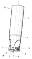
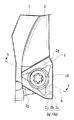
図1は、本発明の一実施形態における切削工具の斜視図である。図2は、図1の切削工具における、切削インサートおよび固定ねじを外した工具ボデーの、インサート取付座およびその周囲の拡大斜視図である。図3は、図2のインサート取付座を底壁面に対向する方向からみた拡大図である。図4は、図3と同じ方向から図1の切削工具の一部をみた拡大図である。図5は、図4のV−V線に沿った切削工具の拡大断面図である。図6は、インサート取付座へ切削インサートを装着した状態を誇張して表した模式図であり、ねじを省いた図である。 FIG. 1 is a perspective view of a cutting tool according to an embodiment of the present invention. FIG. 2 is an enlarged perspective view of the insert mounting seat and its periphery of the tool body from which the cutting insert and the fixing screw are removed in the cutting tool of FIG. FIG. 3 is an enlarged view of the insert mounting seat of FIG. 2 as viewed from the direction facing the bottom wall surface. 4 is an enlarged view of a part of the cutting tool of FIG. 1 from the same direction as FIG. FIG. 5 is an enlarged cross-sectional view of the cutting tool along the line VV in FIG. FIG. 6 is a schematic view exaggeratingly showing a state in which the cutting insert is mounted on the insert mounting seat, and is a view in which screws are omitted.
図1から図5に示すように、この実施形態の切削工具1は、切削インサート2を着脱自在に装着する回転切削工具である。切削工具1は、工具ボデー3を備える。工具ボデー3は、軸線3aを有し、軸線3aは工具ボデー3の先端部3b側から後端部3c側に延びる。工具ボデー3は、全体的にみて略円柱状の輪郭を有する。工具ボデー3には、複数(本実施形態では3つ)のインサート取付座4がある。これらインサート取付座4は、工具ボデー3の先端部3bにおいて軸線3a周りの周方向に互いから等距離に配置されている。しかし工具ボデーのインサート取付座の数は1つでも2つ以上幾つでもよい。各インサート取付座4には、切削インサート2が着脱自在に取り付けられる。したがって、切削工具1では、複数(本実施形態では3つ)の切削インサート2が用いられ、これらの各々を固定するために複数の締めつけねじ(固定ねじ)10が用いられる。
As shown in FIGS. 1 to 5, the
各切削インサート2は、略三角形板状の輪郭形状を有する。各切削インサート2は、ポジティブタイプの切削インサートであるが、ネガティブタイプの切削インサートであってもよい。切削インサート2は、2つの端面としての上面2aおよび下面2bと、上下面の間に延在する周側面2cとを備える。切削インサート2は、上下面を貫通するように延びる、各締めつけねじ10に対応する貫通穴2dを有する。貫通穴2dは、中心軸線Bを有し、その軸線Bに沿って上面側開口部に受凹部2fを有する。
Each cutting
締めつけねじ10は、その長手方向に延びる軸線(不図示)を有し、ねじ山が形成されているねじ部10aと、軸線方向においてねじ部10aの一端に配置されているヘッド部10bとからなる。ヘッド部10bはレンチなどの締付工具が係合可能に構成されていて、ここでは凹部が形成されている。ヘッド部10bは、ねじ部10aよりも直径が大きい。ここでは、ヘッド部10bの外周部のねじ部10a側部分は切頭円錐形状である。しかし、例えばヘッド部10bの外周部は部分的にまたは全体的にさらに外方に膨らむように断面円弧凸状であってもよい。切削インサート2の貫通穴2dの一端(上面側)から締めつけねじ10がそのねじ部10aを先端にして挿入されたとき、最終的に、締めつけねじ10のヘッド部10bが実質的に収容されかつヘッド部10bが当接する受凹部2fが、上記のように、貫通穴2dの上面側開口部に形成されている。
The
切削インサート2では、上面2aと周側面2cとの交差部に沿って切れ刃2gが形成されている。切削インサート2は、上面2aと周側面2cとの交差部の全周に亘って複数の(ここでは3つの)切れ刃2gを有するが、その交差部の少なくとも一部にのみ少なくとも1つの切れ刃が形成されてもよい。上面2aは略三角形形状を有し、3つのコーナ部を有する。各コーナ部に対して切れ刃2gが関係付けられているので、切削インサート2は3つの切れ刃2gを有する。各切れ刃2gは、コーナ部に沿うコーナ切れ刃2hと、このコーナ切れ刃2hから延在する第1切れ刃2iと、同コーナ切れ刃2hから第1切れ刃2iとは反対側に向けて延在する第2切れ刃2jとを含む。3つの切れ刃2gは、貫通穴2dの中心軸線Bに関して、120°回転対称に配置されている。これに対応するように、切削インサート2は、貫通穴2dの中心軸線Bに関して120°回転対称であるように形成されている。切削インサート2では、3つの切れ刃2gは互いに連続するが、互いから独立してもよい。切削工具1に装着された切削インサート2において、上面2aの一部は1つの作用切れ刃2g´のすくい面として機能するように構成されていて、周側面2cの一部は同作用切れ刃2g´の逃げ面として機能するように構成されている。切削インサート2において、種々の変更が可能であり、例えば、上面2aに正のすくい角を付与するための、すくい面としての傾斜面やこの傾斜面を含む凹部や、切削インサートの両面に切れ刃がある場合に設けられるボス面へとつづく立ち上がり壁面が設けられてよい。さらに、切れ刃は全体的にまたは部分的に傾いてよく、切れ刃の部分は直線状であっても、曲線状であってもよい。
In the
この実施形態の回転切削工具1において、複数の切削インサート2は、すべて同一形状とされる。この回転切削工具1は、切削インサート2の使用個数に応じた刃数を有する。したがって説明の簡略化のため、以降は1つの切削インサート2に関して説明するが、他のすべての切削インサート2についても同様である。また、複数の締めつけねじ10や、インサート取付座4についても、すべて同一形状とされる。以降は1つの締めつけねじ10や、インサート取付座4に関して説明するが、他のすべての締めつけねじ10や、インサート取付座4についても同様である。
In the
各インサート取付座4は、底壁面5および側壁面6を有する。インサート取付座4の底壁面5の輪郭形状は、切削インサート2の輪郭形状に対応する。この実施形態では、底壁面5の輪郭形状は、略三角形状とされる。インサート取付座4の底壁面5には、締めつけねじ10に対応するねじ穴7が交差している。つまり底壁面5には、ねじ穴7が開口している。締めつけねじ10は、ねじ穴7に螺入され得る。締めつけねじ10は、ねじ穴7の中心軸線Aに沿って進退可能にねじ穴7に係合することができる。つまり、締めつけねじ10は、ねじ穴7に対して締めつけられたり、緩められたりすることができる。切削インサート2の貫通穴2dを介して締めつけねじ10をねじ穴7に締めつけると、切削インサート2は、インサート取付座4の底壁面5および側壁面6へ押しつけられて固定される。
Each insert mounting seat 4 has a
ねじ穴7付きインサート取付座4を含む、切削インサート2を装着するための装着構造20を、ここでは装着装置と呼称する。ここでは、締めつけねじ10は、装着装置20の構成要素としている。しかし、締めつけねじ10は独立した構造体であるため、締めつけねじを除いた装着構造のことを装着装置としてもよい。
The mounting
この実施形態の工具ボデー3のインサート取付座4は、各々が底壁面5に交差するように延在する壁面である、2つの側壁面(側壁面部分)6を有する。1つは、主拘束面となる第1の側壁面6aである。もう1つは、副拘束面となる第2の側壁面6bである。主拘束面とは、切削インサート2と接触する側壁面6のうち、主体的に作用する側壁面(面部分)のことである。副拘束面とは、切削インサート2と接触する側壁面6のうち、主拘束面以外の側壁面(面部分)のことである。主拘束面は、副拘束面よりも大きく形成されることが好ましい。逆に言えば、切削インサート2と接触する複数の側壁面のうち、最も切削インサート2と接触する面積が広い側壁面を主拘束面と呼称するとよい。この実施形態は、切削インサート2の輪郭形状が略三角形板状であるため、インサート取付座4において、第1の側壁面6aは工具ボデーの基端部3c側に配置され、第2の側壁面6bは工具ボデーの先端部3b側に配置される。第1の側壁面6aは、第2の側壁面6bよりも、(底壁面に沿った幅である)横幅が広く、切削インサート2を固定するときに主体的に作用する。第2の側壁面6bは、第1の側壁面6aが切削インサート2を支持してそれを拘束することを補助する。すなわち、インサート取付座4では、第1の側壁面6aが主拘束面であり、第2の側壁面6bが副拘束面である。切削インサート2は、主拘束面である第1の側壁面6aに当接することで、その回転方向の向きの動きが拘束され、さらに、副拘束面である第2の側壁面6bと接触することで、その位置が特に定まることが好ましい。
The insert mounting seat 4 of the
インサート取付座4では、底壁面5、第1の側壁面6aおよび第2の側壁面6bはそれぞれ平面として実質的に構成されている。しかし、これら壁面には、切削インサートに対応した凹凸などが設けられてもよい。第1の側壁面6aには、底壁面5に沿った方向の途中において凹部6cが設けられている。この凹部6cは、第1の側壁面6aを2つの壁面部に分けているが、設けられなくてもよい。
In the insert mounting seat 4, the
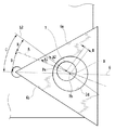
ここで、図3〜図5を用いてさらに説明する。図3および図4は、インサート取付座4の底壁面5に対向する向きからの図であり、図3および図4では底壁面5は紙面に実質的に平行である。図3および図4では、底壁面5におけるねじ穴7の中心軸線Aが投影されて仮想線として示されている。図5は、そのねじ穴7の中心軸線Aを含む平面での切削工具1の断面図である。また、図4は、インサート取付座4の底壁面5にまさに対向する位置からみた図3のインサート取付座4に切削インサート2が取り付けられた状態を示し、よって図5は底壁面5に直交する断面での図である。なお、図5では、インサート取付座4の底壁面5に直交するように延びる線L1が表され、この線L1は底壁面5を延長(拡張)するように定められる第1仮想平面P上でねじ穴7の中心軸線Aと交わる。
Here, it demonstrates further using FIGS. 3-5. 3 and 4 are views from the direction facing the
図5に示すように、ねじ穴7の中心軸線Aは、インサート取付座4の底壁面5の法線方向(つまり線L1)に対して傾斜している。図5におけるねじ穴7の中心軸線Aの底壁面5の法線方向に沿った線L1に対する傾き(以下、法線方向傾き、という)は、図5において定められる傾斜角度Fで表される。この実施形態で傾斜角度F(つまり図5において線L1と中心軸線Aとのなす角度)は、約5°である。
As shown in FIG. 5, the central axis A of the
図5において、ねじ穴7の中心軸線Aは、線L1を基準にすると、インサート取付座4の上方側で切削工具1の外側に向けて傾いている。したがって、ねじ穴7に締めつけねじ10がねじ込まれるとき、ねじ10は工具ボデー3の内側方向に進む。インサート取付座4は、2つの側壁面6a、6b側の座内側部4aと、該座内側部と異なり工具ボデー3の外方に開く座外側部4bとを有するので、換言すると、ねじ穴7の中心軸線Aは、底壁面5から穴奥側に離れるほど、座外側部4bよりも座内側部4aに寄るように、傾斜している。このように、切削工具1では、図5の断面図(第2仮想平面)において、ねじ穴7の中心軸線Aは、側壁面6側の底壁面の部分とインサート内鋭角αをなすように、傾斜している。
In FIG. 5, the central axis A of the
したがって、図3および図4において仮想線として表されたねじ穴7の中心軸線Aは所定の向きに延びている。ここで、第1仮想平面P上に中心軸線Aを投影すると、図3に示すようになる。(底壁面5に略平行な面である)第1仮想平面P上におけるねじ穴7の中心軸線Aの向き(以下、傾斜方向、という)は、狭義には、特に、第1仮想平面上におけるねじ穴7の軸線Aの通過点Paから側壁面6側の方向(図6中の矢印A1参照)とする。図3に示すように、図3におけるねじ穴7の中心軸線Aの傾斜方向は、基準線(基準面)Gに対して定められることができる。
Accordingly, the central axis A of the
ここで、第1の側壁面6aと第2の側壁面6bとの間のコーナ交差部4cは、第1の側壁面6aの延長面と、第2の側壁面6bの延長面とにより定められる交差部6d(図3参照)として近似されることができる。切削インサート2は略三角形板状であるので主として3つの側面を有し、この交差部6dの交差角度は、切削インサート2の隣り合う2つの側面間のインサート内角に相当し、鋭角である。コーナ交差部4c(つまり交差部6d)においては、このコーナ交差部の交差角度を2等分するように第1の側壁面6aと第2の側壁面6bとの間に底壁面5に略直交するように延びる基準面(第3仮想平面)が定められる。この基準面が図3において線Gとして表されている。したがって、図3において、基準線Gは、第1の側壁面6aに沿った線と第2の側壁面6bに沿った線とをそれぞれ延長して交差させたときの、これら2つの延長線の交差部の交差角度の2等分線方向に延びる。図3から明らかなように、投影されたねじ穴7の中心軸線Aは、基準線Gに平行ではなく、傾いている。図3におけるねじ穴7の中心軸線Aの基準線Gに対する傾きは、図3において定められる角度Dで表される。ただし、角度Dは、中心軸線Aと基準線Gとの交差部に対して座内側部4a側において定められる。角度Dの符号は、ここでは第2の側壁面6側bから第1の側壁面6a側に向かう方向を正として定められる。
Here, the
例えば中心軸線Aの傾斜方向の角度Dが約0°のときは、インサート取付座4のねじ穴7に切削インサート2の貫通穴2dを介して締めつけねじ10を螺入することで、第1の側壁面6aと第2の側壁面6bとに、ほぼ均等に、締めつけねじ10への締めつけ力を分散できる。一方、切削工具1の装着装置20のように角度Dが正の角度のときは、切削インサート2は、その周方向で、第1の側壁面6aで主体的に拘束されるようにできる。この実施形態では、中心軸線Aの傾斜方向の角度Dは、約30°とされる。このようにねじ穴7の中心軸線Aが法線方向傾き角度Fおよび傾斜方向傾き角度Dをもって傾斜するようにねじ穴7が形成されると、切削インサート2をインサート取付座4上に載置して締めつけねじ10を締めつけるとき、切削インサート2は、傾斜方向の先にあるインサート取付座4の側壁面6に向かって押しつけられる。
For example, when the angle D in the inclination direction of the central axis A is about 0 °, the
法線方向傾きの角度Fは、1°以上、かつ10°以下の範囲が好ましい。角度Fは、3°以上、かつ6°以下の範囲がさらに好ましい。一方、中心軸線Aの傾斜方向の角度Dは、1°以上、かつ50°以下が好ましい。中心軸線Aの傾斜方向の角度Dは、20°以上、かつ40°以下がさらに好ましい。法線方向傾きの角度Fおよび傾斜方向の角度Dがこのような角度範囲にされると、締めつけねじ10を破断させるようにそれに作用することを大幅に軽減しつつ、締めつけ力を増加する効果が最大限に得られる。そのため切削インサート2の固定が、より安定し、切削インサート2とインサート取付座4との間にすきまが生じることをより確実に防止できる。あるいは、切削中に切削インサート2が動くことをよりしっかりと防止できる。なお法線方向傾きの角度Fが10°を超えると、切削インサート2の貫通穴2dと締めつけねじ10が偏って干渉しやすくなるため好ましくない。また中心軸線Aの傾斜方向の角度Dは、50°を超えると、切削インサート2と第2の側壁面6bとの接触状態が不十分になる可能性が高まるため好ましくない。角度Fおよび角度Dは、それぞれ、切削インサート2の周方向(貫通穴2dの軸線B周囲の方向)において第1の側壁面6aを主拘束面としてかつ第2の側壁面6bを副拘束面として切削インサート2を好適に支持できるように定められるとよい。
The normal direction inclination angle F is preferably in the range of 1 ° or more and 10 ° or less. The angle F is more preferably in the range of 3 ° or more and 6 ° or less. On the other hand, the angle D in the inclination direction of the central axis A is preferably 1 ° or more and 50 ° or less. The angle D in the inclination direction of the central axis A is more preferably 20 ° or more and 40 ° or less. If the angle F of the normal direction inclination and the angle D of the inclination direction are within such an angle range, the effect of increasing the tightening force while greatly reducing the effect of acting on the tightening
さらに、図5および図6から明らかなように、ねじ穴7の中心軸線Aは、切削インサート2の貫通穴の中心軸線Bから、インサート取付座4の内側(すなわち側壁面側)に芯寄せ量Hだけずれて形成される。ただし、ねじ穴7の中心軸線Aが完全に延びる図5の断面図には、現実には、切削インサート2の貫通穴2dの中心軸線Bは表れない。しかし、2つの中心軸線A、Bのずれを表現するべく、図5では、図6に表されている貫通穴2dの中心軸線Bが参考までに投影されて示されている。なお実際の縮尺で図示すると、2つの中心軸線A、Bが互いに対してずれている状態がわかりにくい。そのため図6は、それらがずれている状態を誇張して表した模式図であり、図6を用いてさらなる説明を続ける。ただし、図3および図4と同様に、図6はインサート取付座4の底壁面5に対向する向きからの図であり、図6では底壁面5は紙面に略平行である。したがって、図6において、そこに表される切削インサート2の貫通穴2dの中心軸線Bは実質的に点である。
Further, as is apparent from FIGS. 5 and 6, the center axis A of the
前述のとおり、ねじ穴7の中心軸線Aは底壁面5に対して傾斜しているため、ねじ穴7の中心軸線Aと、インサート取付座4上の切削インサート2の貫通穴2dの中心軸線Bとは平行でない。さらに、ねじ穴7の中心軸線Aは、切削インサート2の貫通穴2dの中心軸線Bに対して、インサート取付座内側(座内側部4a側)にずらされている。そのずれ量は、ここでは芯寄せ量Hで表される。芯寄せ量Hは、インサート取付座4の底壁面5に沿った第1仮想平面P上におけるそれら中心軸線A、B間のずれ量とする。図6では、第1仮想平面Pにおけるねじ穴7の中心軸線Aの通過点Paと、第1仮想平面Pにおける切削インサート2の貫通穴2dの中心軸線Bの通過点Pbとが表されている。ただし、この場合の、貫通穴2dの位置は、インサート取付座4の壁面5、6にしっかりと当接するように載置された切削インサート2における位置である。なお、この第1仮想平面Pは、底壁面5を貫通穴内部にまで延びるように定められる、底壁面5の延長面である。さらに、第1仮想平面P上において、ねじ穴7の中心軸線Aの通過点Paが貫通穴2dの中心軸線Bの通過点Pbからずれている方向を、芯寄せ方向とする。芯寄せ方向は、図6において線L2に沿った方向である(矢印A2参照)。
As described above, since the center axis A of the
この実施形態において、ねじ穴7の中心軸線Aの芯ずれ量Hは、約0.5mmとされる。しかし、これに限定されない。この実施形態では、芯ずれ量Hが約0.5mmと大きくされるが、前述のねじ穴7の中心軸線Aの傾斜との相乗効果により、ねじ10が破断することなく、切削インサート2の固定をより安定させる効果が得られる。
In this embodiment, the misalignment amount H of the central axis A of the
芯寄せ方向は、図6における点Paと点Pbとを通る上記線L2と基準線Gとの間の角度Cで評価することができる。図6にも、図3に示された基準線Gが表されている。芯寄せ方向の角度Cは上記角度Dと同様に定められ、その符号は第2の側壁面6b側から第1の側壁面6a側に向かう方向を正として定められる。
The centering direction can be evaluated by an angle C between the line L2 passing through the point Pa and the point Pb in FIG. 6 also shows the reference line G shown in FIG. The angle C in the centering direction is determined in the same manner as the angle D, and the sign is determined with the direction from the second
芯寄せ方向の角度Cが約0°のときは、第1の側壁面6aと第2の側壁面6bとに、ほぼ均等に締めつけねじへの締めつけ力を分散できる。一方、芯寄せ方向の角度Cが正の角度のときは、切削インサート2は、締めつけねじを締めることで第1の側壁面6aに積極的に押し付けられ、その結果、第1の側壁面6aで主体的に拘束されるようにできる。切削インサート2をインサート取付座4上に載置して締めつけねじ10を締めつけると、切削インサート2は、芯寄せ方向にあるインサート取付座4の少なくとも1つの所定の側壁面6に向かって寄せられる。ただし厳密には、切削インサート2の締めつけ力を制御する要因として、締めつけねじ10の回転に起因する摩擦力の影響も無視できない。したがって、第1の側壁面6aと第2の側壁面6bとに、ほぼ均等に締めつけ力を分散できる芯寄せ方向の角度Cは、厳密には0°ではない。別の言い方をすると、例えば、芯寄せ方向の角度Cが約0°で右ねじの締めつけねじ10を用いるとしたら、第1の側壁面6aの方が第2の側壁面6bよりも切削インサート2を強く拘束する。すなわち芯寄せ方向と締めつけねじ10の回転方向との相乗効果により、第1の側壁面6aを主拘束面とする強力な締めつけ力を得られる。なお本発明は、芯寄せ方向とねじの傾斜方向とが異なる方向とされることに大きな特徴がある。つまり芯寄せ方向とねじ穴軸線の投影傾きの方向とを、それぞれ独立したパラメータとして調整することで、従来は得られなかった、切削インサート2の強固な固定が可能となる。
When the angle C in the centering direction is about 0 °, the tightening force applied to the tightening screw can be distributed almost uniformly on the first
本実施形態では、芯寄せ方向は、第1の側壁面6aに向かう方向とされている。これは、図6において、線L2が第1の側壁面6aと交差していることから明らかである。インサート取付座4の底壁面5に対向する方向からみた図6において、芯寄せ方向の角度Cは、20°以上、かつ90°以下の範囲とされることが好ましい。芯寄せ方向の角度Cは、30°以上、かつ50°以下の範囲とされることがさらに好ましい。芯寄せ方向の角度Cは、20°未満では、従来の切削工具と比較して、締めつけ力の顕著な向上効果は得難い。芯寄せ方向の角度Cが90°を超えると、ねじへの締付力は、切削インサート2を第2の側壁面6bから引き離す方向に作用するため好ましくない。この実施形態の切削工具1で、芯寄せ方向の角度Cは、約35°とされる。芯寄せ方向がこのような方向とされることで、切削インサート2の貫通穴2dを介して締めつけねじをインサート取付座4に締めつけるときに、切削インサート2が第1の側壁面6aにしっかりと押し付けられてそれに密着することができる。なお前述のとおり、この実施形態の切削工具では、締めつけねじが底壁面に対して傾斜して螺合し、その傾斜方向が第1の側壁面6a側を向いている。ねじがそのように傾斜すると、切削インサート2と締めつけねじ10との実際の接触箇所、つまり実際の芯寄せ方向は、芯寄せ方向の角度Cよりも第1の側壁面6a側に移動する。したがって、芯寄せ方向とねじの傾斜方向とのさらなる相乗効果により、第1の側壁面6aをさらに主体的に切削インサート2の支持に作用させることができる。
In the present embodiment, the centering direction is a direction toward the first
次に、ねじの傾斜方向と芯寄せ方向との角度差Eについて説明する。本発明は、芯寄せ方向(図6の矢印A2)と傾斜方向(図6の矢印A1)とが異なる方向とされることに大きな特徴がある(図6で線L2と線Aとは非平行)。角度差Eの符号は、芯寄せ方向つまり線L2を基準として、第2の側壁面6bに向かう方向を正とする。ただし角度差Eの符号を気にしない場合は、角度差Eは単にねじの傾斜方向と芯寄せ方向とのなす角度とされても構わない。切削インサート2の固定をより安定させるためには、傾斜方向を芯寄せ方向と比較して、第2の側壁面6b側に向かう方向(つまり第2の側壁面6b寄りの方向)とすることが好ましい。角度差Eは、1°以上、かつ80°以下の範囲であることが好ましい。角度差Eは、3°以上、かつ10°以下の範囲であることがさらに好ましい。この実施形態で、角度差Eは約5°とされる。角度差Eが80°を超えると、特に90°を超えると、ねじの傾斜による切削インサートの移動および芯寄せによる切削インサートの移動のいずれかが、切削インサート2を第2の側壁面6bから引き離す方向に作用するため好ましくない。
Next, the angle difference E between the screw inclination direction and the centering direction will be described. The present invention is greatly characterized in that the centering direction (arrow A2 in FIG. 6) and the inclination direction (arrow A1 in FIG. 6) are different directions (in FIG. 6, line L2 and line A are not parallel). ). The sign of the angle difference E is positive in the direction toward the second
ねじの傾斜方向および芯寄せ方向は、以上に説明したような、それぞれの方向および角度(C、D、E)とされると、切削インサート2の固定がより安定する。なぜなら、締めつけねじ10を締めつけるとき、切削インサート2は、まずは芯寄せ方向に寄せられ、主拘束面となる第1の側壁面6aと密着する。さらに締めつけねじ10を締めつけると、切削インサート2は、第1の側壁面6aと密着したまま、第2の側壁面6bとよりしっかりと接触するように第2の側壁面6b側に平行移動する。したがって切削インサート2は、第1の側壁面6aと密着したまま、第2の側壁面6bとも接触し、強固に固定される。つまり、芯寄せ方向および傾斜方向をこのように関係付けることで、インサート取付座4の2つの側壁面6は、第1の側壁面6aを主拘束面とし、第2の側壁面6bを副拘束面とするという、意図したとおりの機能および作用を発揮することができる。したがって、本実施形態によれば、切れ刃の姿勢が主拘束面である第1の側壁面6aによって主体的に定められ、切れ刃位置の再現性が高く、高精度な切削加工にも対応できる。あるいは、切削インサートの損傷が抑制される。
If the inclination direction and the centering direction of the screw are the respective directions and angles (C, D, E) as described above, the fixing of the cutting
もしもねじの傾斜だけ、または芯寄せによって切削インサートを寄せるだけの従来の切削工具の場合、あるいは傾斜方向と芯寄せ方向とが同一方向とされた場合、前述のように、切削インサート2の周側面の1つの側面(上面2aの1つの辺部に沿った側面)を第1の側壁面6aに確実に密着させながら、切削インサート2の別の側面(上面2aの別の1つの辺部に沿った側面)を第2の側壁面6bへしっかりと接触させることが難しい。なぜなら、傾斜方向と芯寄せ方向とが同一方向である場合には2つの側壁面6の両方に接触する方向へ切削インサート2を押しつけるため、切削インサートは、どちらの側壁面6に密着するかについて制御が難しく、切削インサートと側壁面との間の密着状態にばらつきが生じやすい。このため副拘束面である第2の側壁面6bへ密着して、第1の側壁面6aには傾いて接触し、結果的に固定が不安定になる場合がある。なぜなら、2つの物体である切削インサート2とインサート取付座4との接触は、製造誤差などを無視した理想状態を除いて、原則的には所謂3点支持に近い状態となるためである。したがって2つの側壁面を用いて切削インサートを支持する場合、一方の側壁面には2箇所で接触するが、他方の側壁面には1箇所しか接触できない。つまり原則的に、一方の側壁面に密着させると、他方の側壁面には密着させられない。この結果、一方の側壁面に優先的に密着するような構造をとらない限り、どちらの側壁面に密着するかは確率的なばらつきが生じる。本発明のこの実施形態では、芯寄せ方向と傾斜方向とを上述のごとく異なる方向とすることで、芯寄せ方向は、第1の側壁面6aに主体的に向かう方向とし、傾斜方向は、芯寄せ方向に比べて両方の側壁面6a、6bに向かう方向とされる。したがって、確実に切削インサート2が第1の側壁面6aに押し付けられつつ、第2の側壁面6bへもしっかりと接触することができ、よって切削インサート2が強固に固定される。
In the case of a conventional cutting tool in which the cutting insert is moved only by the inclination of the screw or by centering, or when the inclination direction and the centering direction are the same direction, as described above, the peripheral side surface of the cutting
本実施形態では、図5に示すように、締めつけねじ10は、しっかりと締め付けられたとき、切削インサートの貫通穴2dとの間に、部分的にすき間を有し得る。しかし、締めつけねじ10が締め付けられたとき、締めつけねじ10のヘッド部10bは、切削インサート2の貫通穴2dを定める面と、貫通穴2dの中心軸線Bの周囲に関して、実質的に全周で接触することが好ましい。例えば、締めつけねじ10のヘッド部10bの外周部を上で述べたように外方に膨らむように断面円弧凸状とすることで、この全周接触を達成することが可能である。代替的にあるいは付加的に、そのような全周接触を達成するように、切削インサートの受凹部2fが、さらに形付けられるとよい。このようにされると、締めつけのときに締めつけねじ10が破断することを防止する効果が最大となる。なお傾斜方向と芯寄せ方向とが上で述べたように異なるため、締めつけねじ10は、切削インサート2の貫通穴画定面と実質的に全周で接触しても、確実に切削インサート2が第1の側壁面6aに当接しつつ、第2の側壁面6bへ接触することが可能となる。
In the present embodiment, as shown in FIG. 5, the tightening
前述のとおり、この実施形態の切削インサート2は、略三角形板状とされる。しかし、本発明はこれに限定されない。本発明の切削インサートは、締めつけねじに対応する貫通穴さえ有していれば、様々な多角形板状や、円形板状などが採用できる。例えば、本発明は六角形板状の切削インサートを用いる切削工具などにも適用可能である。板状にも限定されず、様々な応用が可能である。ただし本発明は、インサート取付座4の側壁面6が主拘束面(または相当部分)および副拘束面(または相当部分)を有する場合に特に効果が高い。すなわち主拘束面となる第1の側壁面6aを主体的に機能させる場合に、本発明は特に効果が高い。この実施形態のように、略三角形板状の切削インサート2を用いる場合、インサート取付座4の側壁面6は、主に2つの壁面部分からなり、かつ2つの壁面の長さが異なるため、第1の側壁面6aおよび第2の側壁面6bを有することとなる。また略三角形板状の切削インサート2は、図1および図4に示すように切れ刃(つまり工具軸線方向に概ね延びる第1切れ刃2i)の長さを長くとれるため、切り込みの大きな切削加工が可能である。切り込みの大きな切削加工では、切削中に切削インサート2が動きやすい。したがって本発明は、略三角形板状の切削インサート2を用いる切削工具1において、特に効果が高い。
As described above, the cutting
切削インサート2の材料は、少なくともその切れ刃およびその付近において、超硬合金、サーメット、セラミックスおよび立方晶窒化ほう素、または、それら硬質材料の表面にコーティングを施された材料、またはダイヤモンドなどの焼結体材料とされるとよい。
The material of the cutting
上記切削工具1は、工作機械に装着されることにより、鋼材などの切削加工に利用できる。本発明は、上記実施形態に限定されず、旋盤用のバイトや、フライス盤などで用いられる種々の回転切削工具などに適用されることができる。本発明は、種々の工具へ適用可能であり、適用切削工具への制約がほとんどない。実施形態には回転切削工具だけを記載したが、本発明は旋盤用の種々の工具にも適用可能である。
The
本発明は、以上に説明した実施形態およびその変形例に限定されない。本発明については、請求の範囲に記載された発明の精神や範囲から離れることなしに、さまざまな改変や変更が可能であることは理解されなければならない。すなわち、本発明には、請求の範囲によって規定される本発明の思想に包含されるあらゆる変形例や応用例、均等物が含まれる。 The present invention is not limited to the embodiment described above and its modifications. It should be understood that various changes and modifications can be made to the present invention without departing from the spirit and scope of the claimed invention. That is, the present invention includes all modifications, applications, and equivalents included in the concept of the present invention defined by the claims.
Claims (11)
前記インサート取付座(4)は、底壁面(5)と、該底壁面に交差するように延在する少なくとも2つの側壁面(6)とを有し、
前記底壁面(5)には、前記ねじ穴(7)が交差し、
前記ねじ穴(7)の中心軸線(A)は、前記底壁面(5)の法線方向に対して傾斜し、
前記インサート取付座に前記切削インサートが載置されたとき、前記底壁面(5)を拡張するように定められる第1仮想平面上において、前記ねじ穴(7)の前記中心軸線(A)の第1通過点は、前記貫通穴の中心軸線(B)の第2通過点から、前記少なくとも2つの側壁面(6)のうちの少なくともいずれか一方側にずれていて、
前記第1仮想平面上において前記ねじ穴の前記中心軸線(A)の前記第1通過点の前記貫通穴の前記中心軸線(B)の前記第2通過点からのずれ方向を芯寄せ方向とし、かつ、前記第1仮想平面上に前記ねじ穴(7)の前記中心軸線(A)を投影した仮想線の方向を傾斜方向とすると、
前記芯寄せ方向と前記傾斜方向とは異なる方向である、
装着装置(20)。 By inserting the tightening screw (10) into the screw hole (7) of the insert mounting seat (4) of the tool body (3) through the through hole (2d) of the cutting insert (2), the cutting insert is inserted into the insert mounting seat. A mounting device (20) adapted to a cutting tool (1) detachably mounted on
The insert mounting seat (4) has a bottom wall surface (5) and at least two side wall surfaces (6) extending so as to intersect the bottom wall surface,
The bottom wall surface (5) intersects with the screw hole (7),
The central axis (A) of the screw hole (7) is inclined with respect to the normal direction of the bottom wall surface (5),
When the cutting insert is placed on the insert mounting seat, the first axis of the central axis (A) of the screw hole (7) on the first imaginary plane defined to expand the bottom wall surface (5). 1 pass point is shifted from the second pass point of the central axis (B) of the through hole to at least one of the at least two side wall surfaces (6),
On the first imaginary plane, the shift direction from the second passing point of the central axis (B) of the through hole of the first passing point of the central axis (A) of the screw hole is a centering direction, And when the direction of the virtual line which projected the central axis (A) of the screw hole (7) on the first virtual plane is the tilt direction,
The centering direction and the inclination direction are different directions.
Mounting device (20).
前記ねじ穴(7)の前記中心軸線(A)は、該第2仮想平面において該ねじ穴(7)よりも前記少なくとも2つの側壁面(6)側の前記底壁面の部分とインサート内鋭角をなすように、傾斜している、
請求項1に記載の装着装置(20)。 When the second virtual plane is defined so as to include the central axis (A) of the screw hole (7) and to be substantially orthogonal to the bottom wall surface,
The central axis (A) of the screw hole (7) has an acute angle in the insert and the portion of the bottom wall surface closer to the at least two side wall surfaces (6) than the screw hole (7) in the second imaginary plane. Slanted,
The mounting device (20) according to claim 1.
前記少なくとも2つの側壁面(6)は、主拘束面としての第1の側壁面(6a)と、副拘束面としての第2の側壁面(6b)とを含み、
前記芯寄せ方向は前記第1および第2の側壁面のうちで前記第1の側壁面(6a)側を向き、前記傾斜方向は前記芯寄せ方向と比較して前記第1および第2の側壁面のうちで前記第2の側壁面(6b)側寄りである、
請求項1または2に記載の装着装置(20)。 The inclination direction is a direction on the side of the at least two side wall surfaces (6) from the first passing point,
The at least two side wall surfaces (6) include a first side wall surface (6a) as a main constraining surface and a second side wall surface (6b) as a sub constraining surface,
The centering direction faces the first side wall surface (6a) side of the first and second side wall surfaces, and the inclined direction is the first and second sides compared to the centering direction. Of the wall surface, it is closer to the second side wall surface (6b) side,
The mounting device (20) according to claim 1 or 2.
前記少なくとも2つの側壁面(6)は、主拘束面としての第1の側壁面(6a)と、副拘束面としての第2の側壁面(6b)とを含み、
前記第1の側壁面(6a)と前記第2の側壁面(6b)とのそれぞれの延長により定められる交差部において、該交差部における交差角度を2等分するように前記第1の側壁面(6a)と前記第2の側壁面(6b)との間に前記底壁面(5)に略直交するように延びる第3仮想平面を定めるとき、
前記傾斜方向および前記芯寄せ方向は該第3仮想平面により境界付けられた2つの領域のうちの前記第1の側壁面(6a)側の領域へ方向付けられている、
請求項1から3のいずれか一項に記載の装着装置(20)。 The inclination direction is a direction on the side of the at least two side wall surfaces (6) from the first passing point,
The at least two side wall surfaces (6) include a first side wall surface (6a) as a main constraining surface and a second side wall surface (6b) as a sub constraining surface,
In the intersection defined by the respective extensions of the first sidewall surface (6a) and the second sidewall surface (6b), the first sidewall surface so that the intersection angle at the intersection is equally divided into two. When a third virtual plane extending so as to be substantially orthogonal to the bottom wall surface (5) is defined between (6a) and the second side wall surface (6b),
The tilt direction and the centering direction are directed to a region on the first side wall surface (6a) side of two regions bounded by the third virtual plane.
The mounting device (20) according to any one of claims 1 to 3.
請求項3または4に記載の装着装置(20)。 Both the tilt direction and the centering direction are oriented so as to intersect the first side wall surface (6a).
The mounting device (20) according to claim 3 or 4.
前記第1仮想平面上において、前記芯寄せ方向の該第3仮想平面に対する角度(C)は、20°以上、かつ90°以下の範囲である、
請求項3から5のいずれか一項に記載の装着装置(20)。 In the intersection defined by the respective extensions of the first sidewall surface (6a) and the second sidewall surface (6b), the first sidewall surface so that the intersection angle at the intersection is equally divided into two. When a third virtual plane extending so as to be substantially orthogonal to the bottom wall surface (5) is defined between (6a) and the second side wall surface (6b),
On the first virtual plane, an angle (C) of the centering direction with respect to the third virtual plane is in a range of 20 ° or more and 90 ° or less.
The mounting device (20) according to any one of claims 3 to 5.
請求項3から7のいずれか一項に記載の装着装置(20)。 The crossing angle of the crossing portion determined by the extension of the first side wall surface (6a) and the second side wall surface (6b) is an acute angle.
The mounting device (20) according to any one of claims 3 to 7.
Priority Applications (1)
| Application Number | Priority Date | Filing Date | Title |
|---|---|---|---|
| JP2015515751A JP5800111B2 (en) | 2013-09-06 | 2014-09-05 | Cutting tool mounting device, tool body and cutting tool |
Applications Claiming Priority (4)
| Application Number | Priority Date | Filing Date | Title |
|---|---|---|---|
| JP2013184554 | 2013-09-06 | ||
| JP2013184554 | 2013-09-06 | ||
| JP2015515751A JP5800111B2 (en) | 2013-09-06 | 2014-09-05 | Cutting tool mounting device, tool body and cutting tool |
| PCT/JP2014/073455 WO2015034037A1 (en) | 2013-09-06 | 2014-09-05 | Mounting device for cutting tool, tool body, and cutting tool |
Publications (2)
| Publication Number | Publication Date |
|---|---|
| JP5800111B2 true JP5800111B2 (en) | 2015-10-28 |
| JPWO2015034037A1 JPWO2015034037A1 (en) | 2017-03-02 |
Family
ID=52628498
Family Applications (1)
| Application Number | Title | Priority Date | Filing Date |
|---|---|---|---|
| JP2015515751A Active JP5800111B2 (en) | 2013-09-06 | 2014-09-05 | Cutting tool mounting device, tool body and cutting tool |
Country Status (5)
| Country | Link |
|---|---|
| US (1) | US9889505B2 (en) |
| EP (1) | EP2954964B1 (en) |
| JP (1) | JP5800111B2 (en) |
| CN (1) | CN104936731B (en) |
| WO (1) | WO2015034037A1 (en) |
Cited By (1)
| Publication number | Priority date | Publication date | Assignee | Title |
|---|---|---|---|---|
| KR20200090188A (en) * | 2017-11-30 | 2020-07-28 | 이스카 엘티디. | Single-sided 3-way indexable milling inserts with high void volume to material volume ratio and insert mills thereof |
Families Citing this family (4)
| Publication number | Priority date | Publication date | Assignee | Title |
|---|---|---|---|---|
| WO2015129770A1 (en) * | 2014-02-26 | 2015-09-03 | 株式会社タンガロイ | Cutting insert, tool body, and cutting tool |
| JP6524590B2 (en) * | 2014-06-24 | 2019-06-05 | 住友電工ハードメタル株式会社 | Cutting tool and tool body |
| CN111761111B (en) * | 2019-04-01 | 2023-03-21 | 京瓷株式会社 | End mill |
| JP6940832B1 (en) * | 2020-09-07 | 2021-09-29 | 株式会社タンガロイ | Rolling tool |
Citations (5)
| Publication number | Priority date | Publication date | Assignee | Title |
|---|---|---|---|---|
| JPH07164213A (en) * | 1993-12-13 | 1995-06-27 | Ngk Spark Plug Co Ltd | Throw-away tool |
| JPH09300110A (en) * | 1996-05-21 | 1997-11-25 | Daishowa Seiki Co Ltd | Cutting tool |
| JP2011020262A (en) * | 2003-05-09 | 2011-02-03 | Kennametal Inc | Cutting tool |
| JP2011051039A (en) * | 2009-08-31 | 2011-03-17 | Kyocera Corp | Cutting insert, cutting tool, and method for manufacturing workpiece to be cut using the same |
| WO2013027211A1 (en) * | 2011-08-22 | 2013-02-28 | Iscar Ltd. | Cutting tool and cutting insert having a clamping bore with spaced apart clamping portions |
Family Cites Families (21)
| Publication number | Priority date | Publication date | Assignee | Title |
|---|---|---|---|---|
| US3284874A (en) * | 1965-11-22 | 1966-11-15 | De Vlieg Machine Co | Cutting tool with removal cutter element |
| BE793105A (en) * | 1971-12-24 | 1973-04-16 | Walter Gmbh Montanwerke | EXCHANGEABLE CUTTING INSERT MILLING TOOL |
| US3740807A (en) * | 1972-02-25 | 1973-06-26 | Metal Cutting Tools Inc | Inserted blade cutting tool with locking pin |
| SE394606B (en) * | 1972-10-18 | 1977-07-04 | Hertel K | CUTTING TOOLS FOR CHIP SEPARATION METALWORKING |
| US4016634A (en) * | 1976-04-19 | 1977-04-12 | Empire Tool Company | Indexable insert type cutting toolholders |
| AT366306B (en) * | 1980-04-04 | 1982-04-13 | Plansee Metallwerk | CUTTING TOOL |
| EP0269918A3 (en) * | 1986-12-01 | 1989-12-06 | Carboloy Inc. | Cutting tool employing a double pin retention assembly |
| FR2608951B1 (en) * | 1986-12-30 | 1994-05-06 | Electro Metallurgie Ste Indle | DEVICE FOR DEMOUNTABLE FIXING OF A CUTTING INSERT ON A TOOL HOLDER |
| SE523655C2 (en) * | 2001-08-09 | 2004-05-04 | Sandvik Ab | Rotatable cutting tool with a cutter that is clampable with a partially flexible clamping screw. |
| JP2003127007A (en) * | 2001-08-10 | 2003-05-08 | Sumitomo Electric Ind Ltd | Throw-away tip |
| IL144855A0 (en) * | 2001-08-12 | 2002-06-30 | Iscar Ltd | Cutting tool |
| US8287213B2 (en) * | 2006-02-16 | 2012-10-16 | Remark Technologies, Inc. | Indexable cutting tool insert for cutting tools |
| JP2008006538A (en) * | 2006-06-29 | 2008-01-17 | Tungaloy Corp | Throw-away cutting tool |
| AT11470U1 (en) * | 2009-06-10 | 2010-11-15 | Ceratizit Austria Gmbh | CUTTING TOOL |
| US8573903B2 (en) * | 2009-11-03 | 2013-11-05 | Kennametal Inc. | Round cutting insert with anti-rotation feature |
| KR101067161B1 (en) * | 2010-01-06 | 2011-09-22 | 대구텍 유한회사 | Cutting inserts for internal grooving and toolholders for them |
| KR101928112B1 (en) * | 2010-12-31 | 2018-12-11 | 다이아몬드 이노베이션즈, 인크. | Method of producing holes and countersinks in polycrystalline bodies |
| CN201931144U (en) * | 2011-02-24 | 2011-08-17 | 王志刚 | Eight-edge indexable tangential blade and milling cutter |
| WO2012153737A1 (en) * | 2011-05-12 | 2012-11-15 | 株式会社タンガロイ | Clamp device for cutting insert, cutting tool, and cutting insert |
| DE102012012980B4 (en) * | 2011-07-22 | 2019-10-17 | Kennametal India Ltd. | drilling |
| KR20140020192A (en) * | 2012-08-08 | 2014-02-18 | 대구텍 유한회사 | Cutting tool assembly |
-
2014
- 2014-09-05 EP EP14841456.8A patent/EP2954964B1/en active Active
- 2014-09-05 WO PCT/JP2014/073455 patent/WO2015034037A1/en active Application Filing
- 2014-09-05 JP JP2015515751A patent/JP5800111B2/en active Active
- 2014-09-05 CN CN201480005281.8A patent/CN104936731B/en active Active
- 2014-09-05 US US14/767,118 patent/US9889505B2/en active Active
Patent Citations (5)
| Publication number | Priority date | Publication date | Assignee | Title |
|---|---|---|---|---|
| JPH07164213A (en) * | 1993-12-13 | 1995-06-27 | Ngk Spark Plug Co Ltd | Throw-away tool |
| JPH09300110A (en) * | 1996-05-21 | 1997-11-25 | Daishowa Seiki Co Ltd | Cutting tool |
| JP2011020262A (en) * | 2003-05-09 | 2011-02-03 | Kennametal Inc | Cutting tool |
| JP2011051039A (en) * | 2009-08-31 | 2011-03-17 | Kyocera Corp | Cutting insert, cutting tool, and method for manufacturing workpiece to be cut using the same |
| WO2013027211A1 (en) * | 2011-08-22 | 2013-02-28 | Iscar Ltd. | Cutting tool and cutting insert having a clamping bore with spaced apart clamping portions |
Cited By (1)
| Publication number | Priority date | Publication date | Assignee | Title |
|---|---|---|---|---|
| KR20200090188A (en) * | 2017-11-30 | 2020-07-28 | 이스카 엘티디. | Single-sided 3-way indexable milling inserts with high void volume to material volume ratio and insert mills thereof |
Also Published As
| Publication number | Publication date |
|---|---|
| EP2954964B1 (en) | 2017-12-06 |
| JPWO2015034037A1 (en) | 2017-03-02 |
| US9889505B2 (en) | 2018-02-13 |
| EP2954964A4 (en) | 2016-09-21 |
| WO2015034037A1 (en) | 2015-03-12 |
| CN104936731A (en) | 2015-09-23 |
| US20150367422A1 (en) | 2015-12-24 |
| EP2954964A1 (en) | 2015-12-16 |
| CN104936731B (en) | 2016-11-09 |
Similar Documents
| Publication | Publication Date | Title |
|---|---|---|
| JP5800111B2 (en) | Cutting tool mounting device, tool body and cutting tool | |
| JP4532120B2 (en) | Tool and cutting insert for chip removal processing provided with a connecting surface provided with curved ridges and grooves between the holder and the insert | |
| KR101064639B1 (en) | Cutting insert and the cutting tool comprising the same | |
| KR101323558B1 (en) | Insert with a mounting hole and toolholder including a cutting insert | |
| US20200368830A1 (en) | Indexable rotary cutting tool and tool body | |
| KR20180063117A (en) | Turning inserts and methods | |
| US9089908B2 (en) | Tip-replaceable cutting tool | |
| US20110116879A1 (en) | Clamping Member, Tool Holder and Indexable Cutting Tool | |
| JP6052712B2 (en) | Cutting tools | |
| JP6245564B2 (en) | Cutting tools | |
| JP2009291925A (en) | Cutting insert and insert detachable cutting tool | |
| US10286459B2 (en) | Machining tool | |
| US11298749B2 (en) | Cutting insert, holder, and cutting tool that includes cutting insert | |
| JP4661229B2 (en) | Gun drill inserts and insert type gun drills | |
| JP2011051039A (en) | Cutting insert, cutting tool, and method for manufacturing workpiece to be cut using the same | |
| JP2006224278A (en) | Insert for milling cutter | |
| JP2011110664A (en) | Throwaway type cutting tool | |
| JP2008290214A (en) | Tip for boring and boring tool using the same | |
| JP6318558B2 (en) | Cutting insert and replaceable edge drilling tool | |
| JP2006187820A (en) | Insert detachable cutting tool | |
| JP2004216495A (en) | Tool holder | |
| JP3852330B2 (en) | Throw-away tip and throw-away drill | |
| JP5272682B2 (en) | Insert detachable face mill | |
| US20180304387A1 (en) | Cutting tool and cutting insert | |
| JP2009034819A (en) | Cutting tool |
Legal Events
| Date | Code | Title | Description |
|---|---|---|---|
| TRDD | Decision of grant or rejection written | ||
| A01 | Written decision to grant a patent or to grant a registration (utility model) |
Free format text: JAPANESE INTERMEDIATE CODE: A01 Effective date: 20150728 |
|
| A61 | First payment of annual fees (during grant procedure) |
Free format text: JAPANESE INTERMEDIATE CODE: A61 Effective date: 20150810 |
|
| R150 | Certificate of patent or registration of utility model |
Ref document number: 5800111 Country of ref document: JP Free format text: JAPANESE INTERMEDIATE CODE: R150 |
|
| RD04 | Notification of resignation of power of attorney |
Free format text: JAPANESE INTERMEDIATE CODE: R3D04 |
|
| R250 | Receipt of annual fees |
Free format text: JAPANESE INTERMEDIATE CODE: R250 |
|
| R250 | Receipt of annual fees |
Free format text: JAPANESE INTERMEDIATE CODE: R250 |
|
| R250 | Receipt of annual fees |
Free format text: JAPANESE INTERMEDIATE CODE: R250 |
|
| R250 | Receipt of annual fees |
Free format text: JAPANESE INTERMEDIATE CODE: R250 |
|
| R250 | Receipt of annual fees |
Free format text: JAPANESE INTERMEDIATE CODE: R250 |
|
| R250 | Receipt of annual fees |
Free format text: JAPANESE INTERMEDIATE CODE: R250 |