EP1734327A1 - Wärmeübertrager, insbesondere Sorptions-,Reaktions- und/oder Wärmerohr - Google Patents
Wärmeübertrager, insbesondere Sorptions-,Reaktions- und/oder Wärmerohr Download PDFInfo
- Publication number
- EP1734327A1 EP1734327A1 EP06012526A EP06012526A EP1734327A1 EP 1734327 A1 EP1734327 A1 EP 1734327A1 EP 06012526 A EP06012526 A EP 06012526A EP 06012526 A EP06012526 A EP 06012526A EP 1734327 A1 EP1734327 A1 EP 1734327A1
- Authority
- EP
- European Patent Office
- Prior art keywords
- fibers
- heat exchanger
- exchanger according
- heat
- sorption
- Prior art date
- Legal status (The legal status is an assumption and is not a legal conclusion. Google has not performed a legal analysis and makes no representation as to the accuracy of the status listed.)
- Granted
Links
- 238000001179 sorption measurement Methods 0.000 title claims abstract description 23
- 238000006243 chemical reaction Methods 0.000 title claims abstract description 13
- 239000000835 fiber Substances 0.000 claims abstract description 81
- 229920000049 Carbon (fiber) Polymers 0.000 claims abstract description 9
- 229910052751 metal Inorganic materials 0.000 claims abstract description 7
- 239000002184 metal Substances 0.000 claims abstract description 7
- 239000004917 carbon fiber Substances 0.000 claims abstract description 5
- 239000011149 active material Substances 0.000 claims abstract description 4
- 238000004519 manufacturing process Methods 0.000 claims abstract 2
- 238000000034 method Methods 0.000 claims description 15
- 230000008569 process Effects 0.000 claims description 12
- 238000009833 condensation Methods 0.000 claims description 8
- 230000005494 condensation Effects 0.000 claims description 8
- 238000001704 evaporation Methods 0.000 claims description 8
- 230000008020 evaporation Effects 0.000 claims description 8
- OKTJSMMVPCPJKN-UHFFFAOYSA-N Carbon Chemical compound [C] OKTJSMMVPCPJKN-UHFFFAOYSA-N 0.000 claims description 6
- 239000011230 binding agent Substances 0.000 claims description 6
- 239000000853 adhesive Substances 0.000 claims description 5
- 230000001070 adhesive effect Effects 0.000 claims description 5
- 239000003507 refrigerant Substances 0.000 claims description 5
- 239000000126 substance Substances 0.000 claims description 4
- 238000003795 desorption Methods 0.000 claims description 3
- 238000004378 air conditioning Methods 0.000 claims description 2
- 238000005057 refrigeration Methods 0.000 claims 1
- 238000000576 coating method Methods 0.000 abstract 1
- 239000012530 fluid Substances 0.000 description 15
- 239000002594 sorbent Substances 0.000 description 8
- 239000007788 liquid Substances 0.000 description 7
- 239000002313 adhesive film Substances 0.000 description 4
- 238000010586 diagram Methods 0.000 description 4
- 238000001994 activation Methods 0.000 description 3
- 230000005484 gravity Effects 0.000 description 3
- 239000010410 layer Substances 0.000 description 3
- 239000000463 material Substances 0.000 description 3
- 230000008929 regeneration Effects 0.000 description 3
- 238000011069 regeneration method Methods 0.000 description 3
- 239000000758 substrate Substances 0.000 description 3
- RYGMFSIKBFXOCR-UHFFFAOYSA-N Copper Chemical compound [Cu] RYGMFSIKBFXOCR-UHFFFAOYSA-N 0.000 description 2
- 230000004913 activation Effects 0.000 description 2
- 230000008901 benefit Effects 0.000 description 2
- 230000008859 change Effects 0.000 description 2
- 238000001816 cooling Methods 0.000 description 2
- 229910052802 copper Inorganic materials 0.000 description 2
- 239000010949 copper Substances 0.000 description 2
- 239000002657 fibrous material Substances 0.000 description 2
- 150000003839 salts Chemical class 0.000 description 2
- 239000004753 textile Substances 0.000 description 2
- XLYOFNOQVPJJNP-UHFFFAOYSA-N water Substances O XLYOFNOQVPJJNP-UHFFFAOYSA-N 0.000 description 2
- WSWCOQWTEOXDQX-MQQKCMAXSA-M (E,E)-sorbate Chemical compound C\C=C\C=C\C([O-])=O WSWCOQWTEOXDQX-MQQKCMAXSA-M 0.000 description 1
- KXGFMDJXCMQABM-UHFFFAOYSA-N 2-methoxy-6-methylphenol Chemical compound [CH]OC1=CC=CC([CH])=C1O KXGFMDJXCMQABM-UHFFFAOYSA-N 0.000 description 1
- 229910000838 Al alloy Inorganic materials 0.000 description 1
- 229910000881 Cu alloy Inorganic materials 0.000 description 1
- UFHFLCQGNIYNRP-UHFFFAOYSA-N Hydrogen Chemical compound [H][H] UFHFLCQGNIYNRP-UHFFFAOYSA-N 0.000 description 1
- 229920000297 Rayon Polymers 0.000 description 1
- 238000010521 absorption reaction Methods 0.000 description 1
- 230000003213 activating effect Effects 0.000 description 1
- 239000013543 active substance Substances 0.000 description 1
- 239000002318 adhesion promoter Substances 0.000 description 1
- 239000012790 adhesive layer Substances 0.000 description 1
- 239000003463 adsorbent Substances 0.000 description 1
- 229910052910 alkali metal silicate Inorganic materials 0.000 description 1
- 229910052782 aluminium Inorganic materials 0.000 description 1
- XAGFODPZIPBFFR-UHFFFAOYSA-N aluminium Chemical compound [Al] XAGFODPZIPBFFR-UHFFFAOYSA-N 0.000 description 1
- 239000012298 atmosphere Substances 0.000 description 1
- 239000002585 base Substances 0.000 description 1
- 239000007833 carbon precursor Substances 0.000 description 1
- 239000003153 chemical reaction reagent Substances 0.000 description 1
- 239000002131 composite material Substances 0.000 description 1
- 150000001875 compounds Chemical class 0.000 description 1
- 238000010276 construction Methods 0.000 description 1
- 230000001419 dependent effect Effects 0.000 description 1
- 238000009792 diffusion process Methods 0.000 description 1
- 238000004090 dissolution Methods 0.000 description 1
- 230000000694 effects Effects 0.000 description 1
- 239000008394 flocculating agent Substances 0.000 description 1
- 230000004907 flux Effects 0.000 description 1
- 239000007789 gas Substances 0.000 description 1
- 230000017525 heat dissipation Effects 0.000 description 1
- 229910052739 hydrogen Inorganic materials 0.000 description 1
- 239000001257 hydrogen Substances 0.000 description 1
- 238000002844 melting Methods 0.000 description 1
- 230000008018 melting Effects 0.000 description 1
- 229910052987 metal hydride Inorganic materials 0.000 description 1
- 150000004681 metal hydrides Chemical class 0.000 description 1
- VNWKTOKETHGBQD-UHFFFAOYSA-N methane Chemical class C VNWKTOKETHGBQD-UHFFFAOYSA-N 0.000 description 1
- 239000000546 pharmaceutical excipient Substances 0.000 description 1
- 239000005011 phenolic resin Substances 0.000 description 1
- 229920001568 phenolic resin Polymers 0.000 description 1
- 238000006116 polymerization reaction Methods 0.000 description 1
- 239000011148 porous material Substances 0.000 description 1
- 230000001681 protective effect Effects 0.000 description 1
- 230000002787 reinforcement Effects 0.000 description 1
- 239000002904 solvent Substances 0.000 description 1
- 229940075554 sorbate Drugs 0.000 description 1
- 239000010935 stainless steel Substances 0.000 description 1
- 229910001220 stainless steel Inorganic materials 0.000 description 1
Images


Classifications
-
- F—MECHANICAL ENGINEERING; LIGHTING; HEATING; WEAPONS; BLASTING
- F28—HEAT EXCHANGE IN GENERAL
- F28D—HEAT-EXCHANGE APPARATUS, NOT PROVIDED FOR IN ANOTHER SUBCLASS, IN WHICH THE HEAT-EXCHANGE MEDIA DO NOT COME INTO DIRECT CONTACT
- F28D15/00—Heat-exchange apparatus with the intermediate heat-transfer medium in closed tubes passing into or through the conduit walls ; Heat-exchange apparatus employing intermediate heat-transfer medium or bodies
- F28D15/02—Heat-exchange apparatus with the intermediate heat-transfer medium in closed tubes passing into or through the conduit walls ; Heat-exchange apparatus employing intermediate heat-transfer medium or bodies in which the medium condenses and evaporates, e.g. heat pipes
- F28D15/04—Heat-exchange apparatus with the intermediate heat-transfer medium in closed tubes passing into or through the conduit walls ; Heat-exchange apparatus employing intermediate heat-transfer medium or bodies in which the medium condenses and evaporates, e.g. heat pipes with tubes having a capillary structure
- F28D15/046—Heat-exchange apparatus with the intermediate heat-transfer medium in closed tubes passing into or through the conduit walls ; Heat-exchange apparatus employing intermediate heat-transfer medium or bodies in which the medium condenses and evaporates, e.g. heat pipes with tubes having a capillary structure characterised by the material or the construction of the capillary structure
-
- F—MECHANICAL ENGINEERING; LIGHTING; HEATING; WEAPONS; BLASTING
- F25—REFRIGERATION OR COOLING; COMBINED HEATING AND REFRIGERATION SYSTEMS; HEAT PUMP SYSTEMS; MANUFACTURE OR STORAGE OF ICE; LIQUEFACTION SOLIDIFICATION OF GASES
- F25B—REFRIGERATION MACHINES, PLANTS OR SYSTEMS; COMBINED HEATING AND REFRIGERATION SYSTEMS; HEAT PUMP SYSTEMS
- F25B35/00—Boiler-absorbers, i.e. boilers usable for absorption or adsorption
- F25B35/04—Boiler-absorbers, i.e. boilers usable for absorption or adsorption using a solid as sorbent
-
- Y—GENERAL TAGGING OF NEW TECHNOLOGICAL DEVELOPMENTS; GENERAL TAGGING OF CROSS-SECTIONAL TECHNOLOGIES SPANNING OVER SEVERAL SECTIONS OF THE IPC; TECHNICAL SUBJECTS COVERED BY FORMER USPC CROSS-REFERENCE ART COLLECTIONS [XRACs] AND DIGESTS
- Y02—TECHNOLOGIES OR APPLICATIONS FOR MITIGATION OR ADAPTATION AGAINST CLIMATE CHANGE
- Y02A—TECHNOLOGIES FOR ADAPTATION TO CLIMATE CHANGE
- Y02A30/00—Adapting or protecting infrastructure or their operation
- Y02A30/27—Relating to heating, ventilation or air conditioning [HVAC] technologies
Definitions
- the invention relates to a heat exchanger, in particular a sorption, reaction and / or heat pipe, according to the preamble of claim 1.
- heat pipes In heat pipes (heat pipes), the heat transfer takes place by an axially circulating fluid which undergoes phase change.
- water is evaporated as a fluid in the heat-absorbing part and passes as water vapor through the actual - well insulated - transport part in the discharge zone, where it condenses under heat release.
- Capillary forces and, if appropriate, gravity
- Such heat pipes can transport a heat flow which is larger by 3 to 4 orders of magnitude than, for example, a copper rod of the same thickness and, in the case of gravity feedback of the condensate, additionally act like a heat valve because the heat flow can only flow in one direction.
- the heat transfer is caused by the pressure difference between evaporation and condensation zone and works even with small temperature differences.
- a sorption heat exchanger which is provided with a substrate containing a sorbent for reaction with a polar gaseous refrigerant or hydrogen.
- a stack having a plurality of heat transfer surfaces having plates is connected to a heat transfer channel, each two of these plates in the reaction space between them pick up discs from the substrate.
- a fibrous material in particular a woven or felt, may serve.
- metal salts are called, which are capable of reacting with the polar gaseous refrigerant to form a complex compound.
- a heat exchanger in particular a sorption, reaction and / or heat pipe, provided with a plurality of fibers, wherein a plurality of the fibers are attached with its one end to or in the wall. The other end of the fibers is spaced from the wall surface.
- the individual fibers are preferably arranged substantially parallel to one another.
- the fibers are preferably perpendicular or approximately perpendicular to the wall surface - and thus parallel to the heat transport direction - aligned, However, to influence a particular direction of the capillary liquid transport and / or too low achieved fiber density in the context of flocking or other attachment or introduction of the fibers may be arranged obliquely to the wall surface, which in the context of flocking, attachment or introduction of the fibers or following this can take place.
- the fibers are preferably applied to the wall surface by means of a flocking process.
- a flocking process Such methods are technically proven and existing devices can be easily adapted to the particular conditions of flocking with the corresponding fiber materials.
- each individual fiber is fastened to the wall via a thermally conductive adhesive film, there is high mechanical strength, which leads to improved durability of the adsorption bed, especially in so-called complex-compound adsorbents (salts) and metal hydrides.
- the fibers are preferably metal fibers, carbon fibers and / or partially activated and / or activated activated carbon fibers. These fibers have good thermal conductivity, so that the heat can be well dissipated or supplied from the outside. Partial activation is understood here to mean that the fiber is activated by controlling the activation process only up to a certain depth of the fiber, so that a comparatively low porosity with correspondingly greater thermal conductivity is present in the core region of the fiber.
- activated carbon fibers are used as flocking agents, there is also the advantage of a very good mass transfer to the macroscopically easily accessible fiber surface with short diffusion paths to the sorption-active centers within the fiber. By adjusting the flocking density and length of the fiber short cut can Even high occupancy densities can be achieved with a correspondingly high absorptive capacity.
- textile fibers such as viscose fibers, or made of a phenolic resin fibers can be used as flocking and coked the same after flocking in the finished composite in a known manner and possibly activated.
- This method can serve in particular to produce a different degree of activation even in the longitudinal direction of the fiber.
- the fiber for example, at the base of a low porosity with correspondingly higher thermal conductivity and at the other end have a high porosity with correspondingly reduced thermal conductivity.
- the applied fiber bed can fulfill both the function of heat conduction and the sorptive absorption of the working medium, whereby (apart from the adhesive film or the adhesive layer) no further substance is required.
- the fibers preferably have a meso and / or microporous structure formed by activating the fibers such that the fibers themselves constitute the sorbent active substance.
- the fibers are coated or impregnated with a sorption or reaction-active material, wherein in particular a combination with improved thermal conductivity is possible.
- the application of the sorption or reaction-active material can also take place in a second process step, ie after the actual flocking.
- auxiliaries solvents, binders, adhesion promoters, etc.
- the sorbents are in the subsequent application preferably in dissolved or dispersed form, wherein the excipients by evaporation, polymerization, converting, etc. after removed from the structure of the application process or converted into inert substances.
- organic or inorganic binders in particular alkali metal silicates are used.
- other temperature-resistant binders which are substantially inert to the sorbent used and sorbate and the metallic heat transfer materials (stainless steel, copper, copper alloys, aluminum, aluminum alloys) are suitable.
- the adhesive preferably contains heat-conductive substances, so that the heat dissipation or feed line is improved.
- ribs are provided on the outside of the sorption, reaction and / or heat pipe, so that the heat can be released or absorbed over a large area outside the pipe. Under certain circumstances, additional surface-enlarging or heat-transfer improving measures are possible.
- the fibers can be fixed in multiple layers.
- the one end of the fiber can be melted or cast in at least one layer. This can be achieved, for example, by means of a clad metal wall into which the fibers penetrate in the molten state and in which they are kept after cooling with good heat transfer and good mechanical stability.
- the flocking takes place here under elevated temperature and optionally a protective gas atmosphere and using a flux for Dissolution of a possibly existing oxide layer.
- the flocking with melting of one end is particularly suitable for metal fibers.
- no fibers are arranged, wherein the fibers in the different regions are preferably structured differently.
- the fibers preferably have a good adhesion to the working medium to be used in the liquid state thereof, so that capillary forces are generated at sufficiently high flocking density, can be held by the larger amounts of liquid working fluid between the fibers and also transported along the wall area by capillary forces. This effect can be used to advantage in heat pipes and the evaporation / condensation zone of sorption tubes.
- fibers are arranged in a partial region, which are arranged obliquely to the wall surface. This can in particular serve to influence a certain direction of the capillary liquid transport, that is, to increase the suction force (capillarity).
- the oblique arrangement of the fibers is preferably carried out by sliding, light pressure before the adhesive film or adhesive film is completely cured.
- Such sorption, reaction and / or heat pipes can preferably be used as part of a motor vehicle air conditioning, in particular to use existing excess energy. Even in stationary industrial and building services, there are applications in which heat must be transported or pumped with low loss.
- the heat pipe 1 shows a heat pipe 1, which contains a working medium 2.
- the heat pipe 1 is flowed around in a first region A by a first fluid A and in a second region B by a second fluid B.
- the first fluid A is air to be heated, which flows in the cold state onto the heat pipe 1 (arrow on the left, above the heat pipe 1) and flows away from the heat pipe 1 in the condition heated by the heat pipe 1 (arrow left, FIG. below the heat pipe 1) and the second fluid B to be cooled air flowing in warm condition on the heat pipe 1 (arrow on the right, above the heat pipe 1) and in the cooled by the heat pipe 1 state from the heat pipe 1 flows away (right arrow, below of the heat pipe 1).
- a plurality of ribs 3 are provided, which flow through the fluids A and B.
- the heat pipe 1 takes place in the region A as a result of cooling or heat release to the first fluid A condensation of the vaporous working fluid 2, which is reflected in the wall portion 4 of the heat pipe 1 (condensation zone).
- the wall portion 4 is shown in the enlarged view.
- the fibers 6 are fibers with good heat conductivity and high adhesiveness.
- the adhesive used is a binder, which also has a good affinity for the working medium used, but is not solved or attacked by this.
- the working medium 2 settles down, accumulates between the fibers 6 and, as shown by two black arrows in the wall portion 4 of Fig. 1, transported by capillary forces from area A to area B, for example, supported by gravity with appropriate heat pipe arrangement.
- the wall portion 4 of the second portion B is formed corresponding to the wall portion 4 of the first portion A. Due to the heat absorbed by the second fluid B evaporates in this area (evaporation zone), the liquid working fluid and passes in consequence of the pressure difference in the vapor state again in the first region A, so that a circulation system in the heat pipe 1 is formed, in which the working fluid running undergoes a change of state.
- a sorption tube 101 is provided with a working means 102 whose outer structure corresponds to that of the heat pipe 1.
- the internal structure of the area A which in the Nutz remedies the adsorption zone and in the regeneration process of Desoprtionszone also consists of a flocked fiber structure, but the Einzelfasem with a sorbent or reagent 103 are occupied (see detailed view of Fig. 4), or in which the fiber gap partially or completely with sorbent and optionally filled with a binder is filled.
- the second region B which corresponds to the evaporation zone in the utilization process and the condensation zone in the regeneration process, and the intermediate region between region A and region B differs from the construction of the heat pipe.
- a plurality of fibers 106 are provided, which according to the first embodiment are oriented essentially perpendicular to the wall surface and occupy a sorption-active layer (not shown in FIG. 1) are activated or in the case of carbon fibers themselves, ie with a pore structure.
- the area B in which the evaporation of the working medium 102 takes place during the utilization process has, in the present case, as shown enlarged in FIG. 4, a plurality of fibers 106 'which are "laid flat", i. are aligned obliquely to the wall surface.
- the region B may have a capillary structure, as known per se.
- the Soprtionsffenmenge in the area A, the fiber length, thickness and density in the area A and B, and the inclination of the fibers in the area B are coordinated so that the maximum in-adsorbable refrigerant quantity of the area A in desorption and condensation in the area B herein can be fully taken up and held by the capillary fiber spaces.
- the fiber length is preferably between 0.5 to 5 mm, in particular between 1 and 3 mm, in this case 2 mm.
- Fiber thickness and occupation density vary within relatively wide limits. Typical are fiber thicknesses in the range of 5 to 200 .mu.m, in particular 10 to 150 .mu.m, in this case 80 .mu.m. Fiber tilt angle, in combination with occupancy density and / or fiber length, can be used to tailor the ratio of capillary volume and capillary force to needs.
Landscapes
- Engineering & Computer Science (AREA)
- Life Sciences & Earth Sciences (AREA)
- Sustainable Development (AREA)
- Physics & Mathematics (AREA)
- Thermal Sciences (AREA)
- Mechanical Engineering (AREA)
- General Engineering & Computer Science (AREA)
- Sorption Type Refrigeration Machines (AREA)
- Catalysts (AREA)
Abstract
Description
- Die Erfindung betrifft einen Wärmeübertrager, insbesondere ein Sorptions-, Reaktions- und/oder Wärmerohr, gemäß dem Oberbegriff des Anspruchs 1.
- Bei Wärmerohren (heatpipes) erfolgt der Wärmetransport durch ein axial zirkulierendes Fluid das dabei Phasenwechsel durchläuft. So wird bei einem bekannten Wärmerohr Wasser als Fluid im wärmeaufnehmenden Teil verdampft und gelangt als Wasserdampf durch den eigentlichen - gut isolierten - Transportteil in die Abgabezone, wo es unter Wärmefreisetzung kondensiert. Durch Kapillarkräfte (und gegebenenfalls Schwerkraft) gelangt die Flüssigkeit in einem die Rohrinnenwand bedeckenden Metalldrahtgeflecht, dem sogenannten Docht, zum Aufnahmeteil zurück. Derartige Wärmerohre können einen um 3 bis 4 Größenordnungen größeren Wärmestrom transportieren als zum Beispiel ein Kupferstab gleicher Dicke und wirken bei Schwerkraftrückführung des Kondensats zusätzlich wie ein Wärmeventil, weil der Wärmestrom nur in eine Richtung fließen kann. Der Wärmetransport wird durch den Druckunterschied zwischen Verdampfungs- und Kondensationszone bewirkt und funktioniert auch bei kleinen Temperaturunterschieden.
- Aus der
WO 00/66954 A1 - Ein derartiger Wärmeübertrager lässt noch Wünsche offen.
- Es ist Aufgabe der Erfindung, einen verbesserten Wärmeübertrager, insbesondere ein verbessertes Sorptions-, Reaktions- und/oder Wärmerohr, zur Verfügung zu stellen.
- Diese Aufgabe wird gelöst durch einen Wärmeübertrager mit den Merkmalen des Anspruchs 1. Vorteilhafte Ausgestaltungen sind Gegenstand der Unteransprüche.
- Erfindungsgemäß ist ein Wärmeübertrager, insbesondere ein Sorptions-, Reaktions- und/oder Wärmerohr, vorgesehen, mit einer Vielzahl von Fasern, wobei eine Mehrzahl der Fasern mit ihrem einen Ende an oder in der Wand angebracht sind. Das andere Ende der Fasern ist beabstandet von der Wandoberfläche angeordnet. Dabei sind die einzelnen Fasern vorzugsweise im Wesentlichen parallel zueinander angeordnet.
- Die Fasern sind vorzugsweise senkrecht oder annähernd senkrecht zur Wandoberfläche - und somit parallel zur Wärmetransportrichtung - ausgerichtet, jedoch können zur Beeinflussung einer bestimmten Richtung des kapillaren Flüssigkeitstransports und/oder bei zu geringer erreichter Faserdichte im Rahmen der Beflockung oder anderen An- oder Einbringung der Fasern dieselben schräg zur Wandoberfläche angeordnet sein, was im Rahmen der Beflockung, An- oder Einbringung der Fasern oder im Anschluss hieran erfolgen kann.
- Die Fasern werden vorzugsweise mittels eines Beflockungsprozesses auf der Wandoberfläche angebracht. Derartige Verfahren sind technisch erprobt und vorhandene Vorrichtungen können leicht an die besonderen Bedingungen im Rahmen einer Beflockung mit den entsprechenden Fasermaterialien angepasst werden.
- Da jede einzelne Faser über einen wärmeleitenden Haftfilm an der Wand befestigt ist, besteht eine hohe mechanische Festigkeit, die vor allem bei sogenannten Complex-Compound-Adsorbentien (Salze) und Metallhydriden zu einer verbesserten Haltbarkeit des Adsorptionsbettes führt.
- Bei den Fasern handelt es sich vorzugsweise um Metallfasern, Kohlefasern und/oder teil- und/oder durchaktivierte Aktivkohlefasern. Diese Fasern sind gut wärmeleitend, so dass die Wärme gut abgeleitet oder von außen zugeleitet werden kann. Unter Teilaktivierung wird vorliegend verstanden, dass die Faser durch Steuerung des Aktivierungsprozesses nur bis zu einer bestimmten Tiefe der Faser aktiviert wird, so dass im Kembereich der Faser eine vergleichsweise geringe Porosität mit entsprechend größerer Wärmeleitfähigkeit vorliegt. Bei der Verwendung aktivierter Kohlefasern als Beflockungsmittel besteht zudem der Vorteil eines sehr guten Stofftransportes an die auch makroskopisch gut zugängliche Faseroberfläche mit kurzen Diffusionswegen zu den sorptionsaktiven Zentren innerhalb der Faser. Durch Anpassung der Beflockungsdichte und Länge des Faser-Kurzschnittes können auch hohe Belegungsdichten mit entsprechend hoher Sorptiv-Aufnahmekapazität erreicht werden.
- An Stelle von Kohlefasern können auch Vorläufersubstanzen hiervon, insbesondere Textilfasern, wie Viskosefasern, oder aus einem Phenolharz hergestellte Fasern als Beflockungsmittel verwendet werden und dieselben nach erfolgter Beflockung im fertigen Verbund auf bekannte Weise verkokt und ggf. aktiviert werden. Dieses Verfahren kann insbesondere dazu dienen, auch in Faser-Längsrichtung einen unterschiedlichen Aktivierungsgrad zu erzeugen. Dadurch kann die Faser beispielsweise am Fußpunkt eine geringe Porosität bei entsprechend höherer Wärmeleitfähigkeit und am anderen Ende eine hohe Porosität bei entsprechend verringerter Wärmeleitfähigkeit aufweisen.
- Bei der Verwendung von teil- und/oder durchaktivierte Aktivkohlefasern kann das applizierte Faserbett sowohl die Funktion der Wärmeleitung als auch der sorptiven Aufnahme des Arbeitsmittels erfüllen, wodurch (außer dem Haftfilm bzw. der Haftschicht) keine weitere Substanz erforderlich ist.
- Die Fasern weisen bevorzugt eine meso- und/oder mikroporöse Struktur auf, die durch Aktivieren der Fasern gebildet wird, so dass die Fasern selbst die sorptionsaktive Substanz darstellen. Alternativ sind die Fasern mit einem sorptions- oder reaktionsaktiven Material belegt oder imprägniert, wobei insbesondere auch eine Kombination mit verbesserter Wärmeleitfähigkeit möglich ist. Die Aufbringung des sorptions- oder reaktionsaktiven Materials kann auch in einem zweiten Prozessschritt erfolgen, d.h. nach der eigentlichen Beflockung. Hierbei können auch Hilfsstoffe (Lösungsmittel, Binder, Haftvermittler etc.) verwendet werden, um die Materialien an den Fasern anzulagern oder aufzukristallisieren. Die Sorptionsmittel liegen bei der nachträglichen Aufbringung bevorzugt in gelöster oder dispergierter Form vor, wobei die Hilfsstoffe durch Abdampfen, Polymerisieren, Umwandeln usw. nach dem Applikationsprozess wieder aus der Struktur entfernt oder in inerte Stoffe umgewandelt werden.
- Als Klebstoff für die Beflockung werden bevorzugt organische oder auch anorganische Binder, insbesondere Alkalisilikate, verwendet. Dabei sind auch andere temperaturbelastbare Binder, die gegenüber dem eingesetzten Sorpionsmittel und Sorbat sowie den metallischen Wärmeübertragermaterialien (Edelstahl, Kupfer, Kupferlegierungen, Aluminium, Aluminiumlegierungen) im Wesentlichen inert sind, geeignet.
- Der Klebstoff enthält bevorzugt wärmeleitende Stoffe, so dass die Wärmeab-oder-zuleitung verbessert wird.
- Zur Verbesserung des Wärmetransports nach bzw. von außen sind außenseitig am Sorptions-, Reaktions- und/oder Wärmerohr bevorzugt direkt oder indirekt angeordnete Rippen vorgesehen, so dass die Wärme großflächig außerhalb des Rohres abgegeben bzw. aufgenommen werden kann. Dabei sind unter Umständen zusätzliche oberflächenvergrößernde oder wärme-übergangsverbessemde Maßnahmen möglich.
- Die Fasern können mehrschichtig fixiert sein.
- Bei der Beflockung kann das eine Ende der Faser in mindestens eine Schicht eingeschmolzen oder eingegossen werden. Dies kann beispielsweise mittels einer plattierten Metallwand, in welche die Fasern im aufgeschmolzenen Zustand eindringen und in der sie nach dem Abkühlen bei gutem Wärmeübergang und guter mechanischer Stabilität gehalten werden. Die Beflockung erfolgt hierbei unter erhöhter Temperatur und gegebenenfalls einer Schutzgasatmosphäre und unter Anwendung eines Flussmittels zur Auflösung einer möglicherweise vorhandenen Oxidschicht. Die Beflockung unter Einschmelzen eines Endes ist insbesondere für Metallfasern geeignet.
- In einem Zwischenbereich, welcher eine Adsorptionszone von einer Verdampfungszone bzw. eine Desorptionszone von einer Kondensationszone trennt, sind vorzugsweise keine Fasern angeordnet, wobei die Fasern in den unterschiedlichen Bereichen bevorzugt unterschiedlich strukturiert sind.
- Die Fasern weisen vorzugsweise eine gute Adhäsion gegenüber dem einzusetzenden Arbeitsmittel im flüssigen Zustand desselben auf, so dass bei ausreichend hoher Beflockungsdichte Kapillarkräfte erzeugt werden, durch die größere Mengen an flüssigem Arbeitsmittel zwischen den Fasern gehalten und auch entlang dem Wandbereich durch Kapillarkräfte transportiert werden können. Dieser Effekt kann vorteilhaft in Wärmerohren und der Verdampfungs-/Kondensationszone von Sorptionsrohren verwendet werden.
- Bevorzugt sind in einem Teilbereich Fasern angeordnet, die schräg zur Wandoberfläche angeordnet sind. Dies kann insbesondere zur Beeinflussung einer bestimmten Richtung des kapillaren Flüssigkeitstransports dienen, d.h die Saugkraft (Kapillarität) erhöhen. Die schräge Anordnung der Fasern erfolgt bevorzugt durch gleitendes, leichtes Andrücken bevor der Klebefilm oder Haftvermittlungsfilm vollständig ausgehärtet ist.
- Derartige Sorptions-, Reaktions- und/oder Wärmerohre können bevorzugt als Teil einer Kraftfahrzeug-Klimaanlage verwendet werden, insbesondere um vorhandene überschüssige Energie zu nutzen. Auch in der stationären Industrie- und Haustechnik gibt es Anwendungsmöglichkeiten, bei denen Wärme verlustarm transportiert oder gepumpt werden muss.
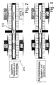
- Im Folgenden wird die Erfindung anhand zweier Ausführungsbeispiele unter Bezugnahme auf die Zeichnung im Einzelnen erläutert. In der Zeichnung zeigen:
- Fig. 1
- eine Prinzipskizze eines Wärmerohres gemäß dem ersten Ausführungsbeispiel,
- Fig. 2
- eine Prinzipskizze eines Sorptions- oder Reaktionsrohres gemäß dem zweiten Ausführungsbeispiel im Nutzprozess,
- Fig. 3
- die Prinzipskizze von Fig. 2 im Regenerationsprozess, und
- Fig. 4
- die Prinzipskizze von Fig. 2 mit Detailansichten.
- Fig. 1 zeigt ein Wärmerohr 1, welches ein Arbeitsmittel 2 enthält. Das Wärmerohr 1 wird in einem ersten Bereich A von einem ersten Fluid A und in einem zweiten Bereich B von einem zweiten Fluid B umströmt. Gemäß dem vorliegenden Ausführungsbeispiel handelt es sich beim ersten Fluid A um zu erwärmende Luft, die in kaltem Zustand auf das Wärmerohr 1 zuströmt (Pfeil links, oberhalb des Wärmerohrs 1) und im durch das Wärmerohr 1 erwärmten Zustand vom Wärmerohr 1 wegströmt (Pfeil links, unterhalb des Wärmerohrs 1) und beim zweiten Fluid B um zu kühlende Luft, die in warmem Zustand auf das Wärmerohr 1 zuströmt (Pfeil rechts, oberhalb des Wärmerohrs 1) und im durch das Wärmerohr 1 gekühlten Zustand vom Wärmerohr 1 wegströmt (Pfeil rechts, unterhalb des Wärmerohrs 1). Zur Verbesserung des Wärmeübergangs von Wärmerohr 1 zum Fluid A oder vom Fluid B zum Wärmerohr 1 sind eine Mehrzahl von Rippen 3 vorgesehen, welche die Fluide A und B durchströmen.
- Im Wärmerohr 1 erfolgt im Bereich A in Folge der Abkühlung oder Wärmeabgabe an das erste Fluid A eine Kondensation des dampfförmigen Arbeitsmittels 2, das sich im Wandbereich 4 des Wärmerohrs 1 niederschlägt (Kondensationszone). Der Wandbereich 4 ist in der vergrößerten Darstellung dargestellt.
- An der Wand 5 des Wärmerohrs 1 sind im Wesentlichen senkrecht von der Wandoberfläche abstehende Fasern 6 vorgesehen. Diese wurden gemäß dem vorliegenden Ausführungsbeispiel mittels eines herkömmlichen elektrostatischen Beflockungsverfahrens, wie es aus der Textilindustrie bekannt ist, aufgebracht und an der Wandoberfläche befestigt. Bei den Fasern 6 handelt es sich vorliegend um gut wärmeleitende Fasern mit einer hohen Adhäsivität. Als Klebstoff dient ein Binder, der ebenfalls eine gute Affinität zum verwendeten Arbeitsmittel besitzt, von diesem aber nicht gelöst oder angegriffen wird.
- An den Fasern 6 schlägt sich das Arbeitsmittel 2 nieder, sammelt sich zwischen den Fasern 6 und wird, wie durch zwei schwarze Pfeile im Wandbereich 4 von Fig. 1 dargestellt, durch Kapillarkräfte vom Bereich A in den Bereich B transportiert, beispielsweise unterstützt durch die Schwerkraft bei entsprechender Wärmerohranordnung.
- Der Wandbereich 4 des zweiten Bereichs B ist entsprechend dem Wandbereich 4 des ersten Bereichs A ausgebildet. Auf Grund der vom zweiten Fluid B aufgenommenen Wärme verdampft in diesem Bereich (Verdampfungszone) das flüssige Arbeitsmittel und gelangt in Folge der Druckdifferenz in dampfförmigem Zustand wieder in den ersten Bereich A, so dass sich ein Kreislaufsystem im Wärmerohr 1 ausbildet, in dem das Arbeitsmittel laufend einer Zustandsänderung unterzogen wird.
- Gemäß dem zweiten Ausführungsbeispiel ist ein Sorptionsrohr 101 mit einem Arbeitsmittel 102 vorgesehen, dessen äußerer Aufbau dem des Wärmerohres 1 entspricht. Die Innenstruktur des Bereichs A, welcher im Nutzprozess der Adsorptionszone und im Regenerationsprozess der Desoprtionszone entspricht, besteht ebenfalls aus einer beflockten Faserstruktur, wobei jedoch die Einzelfasem mit einem Sorptions- oder Reaktionsmittel 103 belegt sind (siehe Detailansicht von Fig. 4), oder bei welcher der Faserzwischenraum teilweise oder vollständig mit Sorptionsmittel und optional mit einem Bindemittel vermischt ausgefüllt ist. Auch der zweite Bereich B, welcher der Verdampfungszone im Nutzungsprozess und der Kondensationszone im Regenerationsprozess entspricht, und der Zwischenbereich zwischen Bereich A und Bereich B unterscheidet sich vom Aufbau des Wärmerohres.
- Im Bereich A, in welchem während des Nutzungsprozesses die Adsorption des Arbeitsmittels 102 erfolgt, sind eine Mehrzahl von Fasern 106 vorgesehen, die entsprechend dem ersten Ausführungsbeispiel im Wesentlichen senkrecht zur Wandoberfläche ausgerichtet sind und mit einer (in Fig. 1 nicht dargestellten) sorptionsaktiven Schicht belegt sind oder im Falle von Kohlefasern selbst aktiviert, d.h. mit einer Porenstruktur, versehen sind.
- In einem relativ kleinen Zwischenbereich zwischen Bereich A und Bereich B sind vorliegend keine Fasern vorgesehen, da dort ein axialer Flüssigkeitstransport unterbunden werden muss.
- Der Bereich B, in welchem während des Nutzungsprozesses die Verdampfung des Arbeitsmittels 102 erfolgt, besitzt vorliegend, wie in Fig. 4 vergrößert dargestellt, eine Mehrzahl von Fasern 106', die "flachgelegt", d.h. schräg zur Wandoberfläche ausgerichtet sind. Alternativ kann der Bereich B eine Kapillarstruktur besitzen, wie sie an sich bekannt ist.
- Die Soprtionsmittelmenge im Bereich A, die Faserlänge, -dicke und ―dichte im Bereich A und B, sowie die Neigung der Fasern im Bereich B sind so aufeinander abgestimmt, dass die maximal im Betrieb adsorbierbare Kältemittelmenge des Bereichs A bei Desorption und Kondensation in dem Bereich B hierin von den kapillaren Faserzwischenräumen vollständig aufgenommen und gehalten werden kann. Die Faserlänge beträgt vorzugsweise zwischen 0,5 bis 5 mm, insbesondere zwischen 1 und 3 mm, vorliegend 2 mm. Je nach Hauptzweck der Faserstruktur, die je nach Ausführungsform die Funktionen "mechanische Armierung eines Sorptions- oder Reaktionsbettes", "Erhöhung der von der Wand weggerichteten Wärmeleitfähigkeit", "Bildung einer Kältemittel transportierenden oder haltenden Kapillarstruktur" oder "Bildung eines aktivierten Kohlefaserbettes" können Material, Faserdicke und Belegungsdichte in relativ weiten Grenzen variieren. Typisch sind Faserdicken im Bereich von 5 bis 200 µm, insbesondere 10 bis 150 µm, vorliegend 80 µm. Der Faser-Neigungswinkel kann in Kombination mit der Belegungsdichte und/oder der Faserlänge dazu benutzt werden, um das Verhältnis von Kapillarvolumen und Kapillarkraft an die Bedürfnisse anzupassen.
Claims (16)
- Wärmeübertrager, insbesondere Sorptions-, Reaktions- und/oder Wärmerohr, mit einer Vielzahl von Fasern (6; 106), wobei eine Mehrzahl der Fasern (6; 106 und 106') mit ihrem einen Ende an oder in der Wand angebracht sind.
- Wärmeübertrager nach Anspruch 1, dadurch gekennzeichnet, dass die Fasern (6; 106) senkrecht oder annähernd senkrecht zur Wandoberfläche ausgerichtet sind.
- Wärmeübertrager nach Anspruch 1 oder 2, dadurch gekennzeichnet, dass die Fasern (6; 106) mittels eines Beflockungsprozesses auf der Wandoberfläche angebracht sind.
- Wärmeübertrager nach einem der vorhergehenden Ansprüche, dadurch gekennzeichnet, dass die Fasern (6; 106) Metallfasem, Kohlefasern und/oder teil- und/oder durchaktivierte Aktivkohlefasem sind.
- Wärmeübertrager nach einem der vorhergehenden Ansprüche, dadurch gekennzeichnet, dass die Fasern (6; 106) eine meso- und/oder mikroporöse Struktur aufweisen.
- Wärmeübertrager nach einem der vorhergehenden Ansprüche, dadurch gekennzeichnet, dass die Fasern (6; 106) am Fußpunkt eine geringe Porosität bei entsprechend höherer Wärmeleitfähigkeit und am anderen Ende eine hohe Porosität bei entsprechend verringerter Wärmeleitfähigkeit aufweisen.
- Wärmeübertrager nach einem der vorhergehenden Ansprüche, dadurch gekennzeichnet, dass die Fasern (6; 106) mit einem sorptions-oder reaktionsaktiven Material belegt oder imprägniert sind.
- Wärmeübertrager nach einem der vorhergehenden Ansprüche, dadurch gekennzeichnet, dass als Klebstoff kältemittelbeständige Binder verwendet werden.
- Wärmeübertrager nach einem der vorhergehenden Ansprüche, dadurch gekennzeichnet, dass der Klebstoff wärmeleitende Stoffe enthält.
- Wärmeübertrager nach einem der vorhergehenden Ansprüche, dadurch gekennzeichnet, dass die Fasern mehrschichtig fixiert sind.
- Wärmeübertrager nach einem der vorhergehenden Ansprüche, dadurch gekennzeichnet, dass die Fasern mit einem Ende in mindestens eine Schicht eingeschmolzen oder eingegossen sind.
- Wärmeübertrager nach einem der vorhergehenden Ansprüche, dadurch gekennzeichnet, dass in einem Zwischenbereich, welcher eine Adsorptionszone von einer Verdampfungszone bzw. eine Desorptionszone von einer Kondensationszone trennt, keine Fasern (106, 106') angeordnet sind.
- Wärmeübertrager nach einem der vorhergehenden Ansprüche, dadurch gekennzeichnet, dass in einem Bereich, insbesondere einem Teilbereich, Fasern (106') angeordnet sind, die schräg zur Wandoberfläche angeordnet sind.
- Verfahren zur Herstellung eines Wärmeübertragers, dadurch gekennzeichnet, dass Fasern (6; 106, 106') mittels eines Beflockungsverfahrens auf einer Wandoberfläche aufgebracht werden.
- Verfahren zur Herstellung eines Wärmeübertragers, dadurch gekennzeichnet, dass Fasern (6; 106, 106') in eine aufgeschmolzene Schicht mit ihrem einen Ende eingelagert werden.
- Verwendung eines Wärmeübertragers, insbesondere eines Sorptions-, Reaktions- und/oder Wärmerohrs, nach einem der Ansprüche 1 bis 13 als Teil einer Kraftfahrzeug-Klimaanlage, als Teil einer Adsorptions-Wärmepumpe oder Kälteanlage für die Industrie- oder Haustechnik.
Applications Claiming Priority (1)
| Application Number | Priority Date | Filing Date | Title |
|---|---|---|---|
| DE10528204 | 2005-06-17 |
Publications (2)
| Publication Number | Publication Date |
|---|---|
| EP1734327A1 true EP1734327A1 (de) | 2006-12-20 |
| EP1734327B1 EP1734327B1 (de) | 2010-02-24 |
Family
ID=37074637
Family Applications (1)
| Application Number | Title | Priority Date | Filing Date |
|---|---|---|---|
| EP06012526A Expired - Lifetime EP1734327B1 (de) | 2005-06-17 | 2006-06-19 | Wärmeübertrager, insbesondere Sorptions-,Reaktions- und/oder Wärmerohr |
Country Status (3)
| Country | Link |
|---|---|
| EP (1) | EP1734327B1 (de) |
| AT (1) | ATE458978T1 (de) |
| DE (1) | DE502006006218D1 (de) |
Citations (6)
| Publication number | Priority date | Publication date | Assignee | Title |
|---|---|---|---|---|
| US4759516A (en) * | 1985-09-30 | 1988-07-26 | Ronald D. Grose | Cascaded turbulence generation inhibitor |
| DE4130976A1 (de) * | 1991-09-18 | 1993-03-25 | Sippel Rudolf | Heat-pipe |
| EP0733871A1 (de) * | 1995-03-21 | 1996-09-25 | KM Europa Metal Aktiengesellschaft | Austauscherrohr für einen Wärmeaustauscher |
| US5785088A (en) * | 1997-05-08 | 1998-07-28 | Wuh Choung Industrial Co., Ltd. | Fiber pore structure incorporate with a v-shaped micro-groove for use with heat pipes |
| US6427765B1 (en) * | 1998-09-29 | 2002-08-06 | Korea Electronics Telecomm | Heat-pipe having woven-wired wick and method for manufacturing the same |
| US20040123980A1 (en) * | 2000-07-14 | 2004-07-01 | Queheillalt Douglas T. | Heat exchange foam |
-
2006
- 2006-06-19 DE DE502006006218T patent/DE502006006218D1/de not_active Expired - Lifetime
- 2006-06-19 EP EP06012526A patent/EP1734327B1/de not_active Expired - Lifetime
- 2006-06-19 AT AT06012526T patent/ATE458978T1/de active
Patent Citations (6)
| Publication number | Priority date | Publication date | Assignee | Title |
|---|---|---|---|---|
| US4759516A (en) * | 1985-09-30 | 1988-07-26 | Ronald D. Grose | Cascaded turbulence generation inhibitor |
| DE4130976A1 (de) * | 1991-09-18 | 1993-03-25 | Sippel Rudolf | Heat-pipe |
| EP0733871A1 (de) * | 1995-03-21 | 1996-09-25 | KM Europa Metal Aktiengesellschaft | Austauscherrohr für einen Wärmeaustauscher |
| US5785088A (en) * | 1997-05-08 | 1998-07-28 | Wuh Choung Industrial Co., Ltd. | Fiber pore structure incorporate with a v-shaped micro-groove for use with heat pipes |
| US6427765B1 (en) * | 1998-09-29 | 2002-08-06 | Korea Electronics Telecomm | Heat-pipe having woven-wired wick and method for manufacturing the same |
| US20040123980A1 (en) * | 2000-07-14 | 2004-07-01 | Queheillalt Douglas T. | Heat exchange foam |
Also Published As
| Publication number | Publication date |
|---|---|
| ATE458978T1 (de) | 2010-03-15 |
| EP1734327B1 (de) | 2010-02-24 |
| DE502006006218D1 (de) | 2010-04-08 |
Similar Documents
| Publication | Publication Date | Title |
|---|---|---|
| DE102006008786B4 (de) | Adsorptions-Wärmepumpe, Adsorptions-Kältemaschine und darin enthaltene Adsorberelemente auf Basis eines offenporigen wärmeleitenden Festkörpers | |
| EP2473811B1 (de) | Flächige kältemittel-zufuhr und -verteilung für einen wärmetauscher in sorptionsmaschinen | |
| AT522326B1 (de) | Kühlvorrichtung | |
| DE112019003618T5 (de) | Wärmerohre umfassend dochtstrukturen mit variabler durchlässigkeit | |
| EP3084321B1 (de) | Adsorberstruktur | |
| EP1859209B1 (de) | Verfahren zur herstellung eines adsorberwärmetauschers | |
| EP0197108A1 (de) | Wärmetauscher | |
| DE2235792A1 (de) | Vorrichtung zur uebertragung von waermeenergie | |
| DE112011103811B4 (de) | Festkörpersorptionskühlung | |
| DE102008013134A1 (de) | Wärmetauschvorrichtung und Verfahren zum Herstellen eines Wärmetauschelements für eine Wärmetauschvorrichtung | |
| WO2007073849A2 (de) | Sorptionswärmeübertragerwand und sorptionswärmeübertrager | |
| DE60126282T2 (de) | Adsorptionskältevorrichtung | |
| AT409547B (de) | Bauelement und verfahren zu dessen herstellung | |
| DE102006028372A1 (de) | Wärmeübertrager, insbesondere Sorptions-, Reaktions- und/oder Wärmerohr | |
| DE102020204498A1 (de) | Bremssattel für eine Scheibenbremse für ein Fahrzeug und Verfahren zum Herstellen eines Bremssattels | |
| DE602005005114T2 (de) | Thermochemischer Reaktor für Kühl- und/oder Heizgerät | |
| EP2418450A2 (de) | Wärmeübertrager aus einer dreidimensionalen textilen Struktur, Verfahren zu dessen Herstellung und dessen Verwendung | |
| EP1734327B1 (de) | Wärmeübertrager, insbesondere Sorptions-,Reaktions- und/oder Wärmerohr | |
| DE102022111460A1 (de) | Batterieanordnung mit Kapillaranordnungen | |
| EP1920202B1 (de) | Anordnung von wärmetauscherplatten, die in thermischem kontakt mit einem adsorbens stehen | |
| DE102015219688B4 (de) | Adsorber, verfahren zur herstellung eines adsorbers und fahrzeug mit einem adsorber | |
| WO2017016647A1 (de) | Wärmeübertragungsrohr, wärmespeicher und verfahren zum herstellen eines wärmeübertragungsrohrs | |
| DE10047503A1 (de) | Sorptionsreaktor | |
| DE102007016306A1 (de) | Verdampferbaugruppe, insbesondere für einen Verdampferbrenner eines Fahrzeugheizgerätes, und Verfahren zur Herstellung einer Verdampferbaugruppe | |
| EP1765492A1 (de) | Formkörper aus pulvern oder granalien, verfahren zu ihrer herstellung und ihre verwendung |
Legal Events
| Date | Code | Title | Description |
|---|---|---|---|
| PUAI | Public reference made under article 153(3) epc to a published international application that has entered the european phase |
Free format text: ORIGINAL CODE: 0009012 |
|
| AK | Designated contracting states |
Kind code of ref document: A1 Designated state(s): AT BE BG CH CY CZ DE DK EE ES FI FR GB GR HU IE IS IT LI LT LU LV MC NL PL PT RO SE SI SK TR |
|
| AX | Request for extension of the european patent |
Extension state: AL BA HR MK YU |
|
| 17P | Request for examination filed |
Effective date: 20070620 |
|
| 17Q | First examination report despatched |
Effective date: 20070719 |
|
| AKX | Designation fees paid |
Designated state(s): AT BE BG CH CY CZ DE DK EE ES FI FR GB GR HU IE IS IT LI LT LU LV MC NL PL PT RO SE SI SK TR |
|
| GRAP | Despatch of communication of intention to grant a patent |
Free format text: ORIGINAL CODE: EPIDOSNIGR1 |
|
| GRAS | Grant fee paid |
Free format text: ORIGINAL CODE: EPIDOSNIGR3 |
|
| GRAA | (expected) grant |
Free format text: ORIGINAL CODE: 0009210 |
|
| AK | Designated contracting states |
Kind code of ref document: B1 Designated state(s): AT BE BG CH CY CZ DE DK EE ES FI FR GB GR HU IE IS IT LI LT LU LV MC NL PL PT RO SE SI SK TR |
|
| REG | Reference to a national code |
Ref country code: GB Ref legal event code: FG4D Free format text: NOT ENGLISH |
|
| REG | Reference to a national code |
Ref country code: CH Ref legal event code: EP |
|
| REG | Reference to a national code |
Ref country code: IE Ref legal event code: FG4D Free format text: LANGUAGE OF EP DOCUMENT: GERMAN |
|
| REF | Corresponds to: |
Ref document number: 502006006218 Country of ref document: DE Date of ref document: 20100408 Kind code of ref document: P |
|
| REG | Reference to a national code |
Ref country code: NL Ref legal event code: VDEP Effective date: 20100224 |
|
| LTIE | Lt: invalidation of european patent or patent extension |
Effective date: 20100224 |
|
| PG25 | Lapsed in a contracting state [announced via postgrant information from national office to epo] |
Ref country code: IS Free format text: LAPSE BECAUSE OF FAILURE TO SUBMIT A TRANSLATION OF THE DESCRIPTION OR TO PAY THE FEE WITHIN THE PRESCRIBED TIME-LIMIT Effective date: 20100624 Ref country code: PT Free format text: LAPSE BECAUSE OF FAILURE TO SUBMIT A TRANSLATION OF THE DESCRIPTION OR TO PAY THE FEE WITHIN THE PRESCRIBED TIME-LIMIT Effective date: 20100625 Ref country code: LT Free format text: LAPSE BECAUSE OF FAILURE TO SUBMIT A TRANSLATION OF THE DESCRIPTION OR TO PAY THE FEE WITHIN THE PRESCRIBED TIME-LIMIT Effective date: 20100224 |
|
| PG25 | Lapsed in a contracting state [announced via postgrant information from national office to epo] |
Ref country code: SI Free format text: LAPSE BECAUSE OF FAILURE TO SUBMIT A TRANSLATION OF THE DESCRIPTION OR TO PAY THE FEE WITHIN THE PRESCRIBED TIME-LIMIT Effective date: 20100224 Ref country code: LV Free format text: LAPSE BECAUSE OF FAILURE TO SUBMIT A TRANSLATION OF THE DESCRIPTION OR TO PAY THE FEE WITHIN THE PRESCRIBED TIME-LIMIT Effective date: 20100224 Ref country code: FI Free format text: LAPSE BECAUSE OF FAILURE TO SUBMIT A TRANSLATION OF THE DESCRIPTION OR TO PAY THE FEE WITHIN THE PRESCRIBED TIME-LIMIT Effective date: 20100224 Ref country code: PL Free format text: LAPSE BECAUSE OF FAILURE TO SUBMIT A TRANSLATION OF THE DESCRIPTION OR TO PAY THE FEE WITHIN THE PRESCRIBED TIME-LIMIT Effective date: 20100224 |
|
| REG | Reference to a national code |
Ref country code: IE Ref legal event code: FD4D |
|
| PG25 | Lapsed in a contracting state [announced via postgrant information from national office to epo] |
Ref country code: NL Free format text: LAPSE BECAUSE OF FAILURE TO SUBMIT A TRANSLATION OF THE DESCRIPTION OR TO PAY THE FEE WITHIN THE PRESCRIBED TIME-LIMIT Effective date: 20100224 Ref country code: SE Free format text: LAPSE BECAUSE OF FAILURE TO SUBMIT A TRANSLATION OF THE DESCRIPTION OR TO PAY THE FEE WITHIN THE PRESCRIBED TIME-LIMIT Effective date: 20100224 Ref country code: CY Free format text: LAPSE BECAUSE OF FAILURE TO SUBMIT A TRANSLATION OF THE DESCRIPTION OR TO PAY THE FEE WITHIN THE PRESCRIBED TIME-LIMIT Effective date: 20100224 Ref country code: IE Free format text: LAPSE BECAUSE OF FAILURE TO SUBMIT A TRANSLATION OF THE DESCRIPTION OR TO PAY THE FEE WITHIN THE PRESCRIBED TIME-LIMIT Effective date: 20100224 Ref country code: GR Free format text: LAPSE BECAUSE OF FAILURE TO SUBMIT A TRANSLATION OF THE DESCRIPTION OR TO PAY THE FEE WITHIN THE PRESCRIBED TIME-LIMIT Effective date: 20100525 Ref country code: ES Free format text: LAPSE BECAUSE OF FAILURE TO SUBMIT A TRANSLATION OF THE DESCRIPTION OR TO PAY THE FEE WITHIN THE PRESCRIBED TIME-LIMIT Effective date: 20100604 Ref country code: EE Free format text: LAPSE BECAUSE OF FAILURE TO SUBMIT A TRANSLATION OF THE DESCRIPTION OR TO PAY THE FEE WITHIN THE PRESCRIBED TIME-LIMIT Effective date: 20100224 Ref country code: RO Free format text: LAPSE BECAUSE OF FAILURE TO SUBMIT A TRANSLATION OF THE DESCRIPTION OR TO PAY THE FEE WITHIN THE PRESCRIBED TIME-LIMIT Effective date: 20100224 |
|
| PG25 | Lapsed in a contracting state [announced via postgrant information from national office to epo] |
Ref country code: SK Free format text: LAPSE BECAUSE OF FAILURE TO SUBMIT A TRANSLATION OF THE DESCRIPTION OR TO PAY THE FEE WITHIN THE PRESCRIBED TIME-LIMIT Effective date: 20100224 Ref country code: CZ Free format text: LAPSE BECAUSE OF FAILURE TO SUBMIT A TRANSLATION OF THE DESCRIPTION OR TO PAY THE FEE WITHIN THE PRESCRIBED TIME-LIMIT Effective date: 20100224 Ref country code: BG Free format text: LAPSE BECAUSE OF FAILURE TO SUBMIT A TRANSLATION OF THE DESCRIPTION OR TO PAY THE FEE WITHIN THE PRESCRIBED TIME-LIMIT Effective date: 20100524 |
|
| PGFP | Annual fee paid to national office [announced via postgrant information from national office to epo] |
Ref country code: GB Payment date: 20100621 Year of fee payment: 5 |
|
| BERE | Be: lapsed |
Owner name: BEHR G.M.B.H. & CO. KG Effective date: 20100630 |
|
| PLBE | No opposition filed within time limit |
Free format text: ORIGINAL CODE: 0009261 |
|
| STAA | Information on the status of an ep patent application or granted ep patent |
Free format text: STATUS: NO OPPOSITION FILED WITHIN TIME LIMIT |
|
| PG25 | Lapsed in a contracting state [announced via postgrant information from national office to epo] |
Ref country code: DK Free format text: LAPSE BECAUSE OF FAILURE TO SUBMIT A TRANSLATION OF THE DESCRIPTION OR TO PAY THE FEE WITHIN THE PRESCRIBED TIME-LIMIT Effective date: 20100224 Ref country code: MC Free format text: LAPSE BECAUSE OF NON-PAYMENT OF DUE FEES Effective date: 20100630 |
|
| REG | Reference to a national code |
Ref country code: CH Ref legal event code: PL |
|
| 26N | No opposition filed |
Effective date: 20101125 |
|
| PG25 | Lapsed in a contracting state [announced via postgrant information from national office to epo] |
Ref country code: IT Free format text: LAPSE BECAUSE OF FAILURE TO SUBMIT A TRANSLATION OF THE DESCRIPTION OR TO PAY THE FEE WITHIN THE PRESCRIBED TIME-LIMIT Effective date: 20100224 |
|
| PG25 | Lapsed in a contracting state [announced via postgrant information from national office to epo] |
Ref country code: LI Free format text: LAPSE BECAUSE OF NON-PAYMENT OF DUE FEES Effective date: 20100630 Ref country code: CH Free format text: LAPSE BECAUSE OF NON-PAYMENT OF DUE FEES Effective date: 20100630 |
|
| PG25 | Lapsed in a contracting state [announced via postgrant information from national office to epo] |
Ref country code: BE Free format text: LAPSE BECAUSE OF NON-PAYMENT OF DUE FEES Effective date: 20100630 |
|
| GBPC | Gb: european patent ceased through non-payment of renewal fee |
Effective date: 20110619 |
|
| PG25 | Lapsed in a contracting state [announced via postgrant information from national office to epo] |
Ref country code: GB Free format text: LAPSE BECAUSE OF NON-PAYMENT OF DUE FEES Effective date: 20110619 |
|
| PG25 | Lapsed in a contracting state [announced via postgrant information from national office to epo] |
Ref country code: HU Free format text: LAPSE BECAUSE OF FAILURE TO SUBMIT A TRANSLATION OF THE DESCRIPTION OR TO PAY THE FEE WITHIN THE PRESCRIBED TIME-LIMIT Effective date: 20100825 Ref country code: LU Free format text: LAPSE BECAUSE OF NON-PAYMENT OF DUE FEES Effective date: 20100619 |
|
| PG25 | Lapsed in a contracting state [announced via postgrant information from national office to epo] |
Ref country code: TR Free format text: LAPSE BECAUSE OF FAILURE TO SUBMIT A TRANSLATION OF THE DESCRIPTION OR TO PAY THE FEE WITHIN THE PRESCRIBED TIME-LIMIT Effective date: 20100224 |
|
| REG | Reference to a national code |
Ref country code: AT Ref legal event code: MM01 Ref document number: 458978 Country of ref document: AT Kind code of ref document: T Effective date: 20110619 |
|
| PG25 | Lapsed in a contracting state [announced via postgrant information from national office to epo] |
Ref country code: AT Free format text: LAPSE BECAUSE OF NON-PAYMENT OF DUE FEES Effective date: 20110619 |
|
| REG | Reference to a national code |
Ref country code: DE Ref legal event code: R082 Ref document number: 502006006218 Country of ref document: DE Representative=s name: GRAUEL, ANDREAS, DIPL.-PHYS. DR. RER. NAT., DE |
|
| REG | Reference to a national code |
Ref country code: DE Ref legal event code: R082 Ref document number: 502006006218 Country of ref document: DE Representative=s name: GRAUEL, ANDREAS, DIPL.-PHYS. DR. RER. NAT., DE Effective date: 20150226 Ref country code: DE Ref legal event code: R081 Ref document number: 502006006218 Country of ref document: DE Owner name: MAHLE INTERNATIONAL GMBH, DE Free format text: FORMER OWNER: BEHR GMBH & CO. KG, 70469 STUTTGART, DE Effective date: 20150226 |
|
| REG | Reference to a national code |
Ref country code: FR Ref legal event code: PLFP Year of fee payment: 11 |
|
| REG | Reference to a national code |
Ref country code: FR Ref legal event code: PLFP Year of fee payment: 12 |
|
| REG | Reference to a national code |
Ref country code: FR Ref legal event code: PLFP Year of fee payment: 13 |
|
| PGFP | Annual fee paid to national office [announced via postgrant information from national office to epo] |
Ref country code: FR Payment date: 20190625 Year of fee payment: 14 |
|
| PGFP | Annual fee paid to national office [announced via postgrant information from national office to epo] |
Ref country code: DE Payment date: 20200831 Year of fee payment: 15 |
|
| PG25 | Lapsed in a contracting state [announced via postgrant information from national office to epo] |
Ref country code: FR Free format text: LAPSE BECAUSE OF NON-PAYMENT OF DUE FEES Effective date: 20200630 |
|
| REG | Reference to a national code |
Ref country code: DE Ref legal event code: R119 Ref document number: 502006006218 Country of ref document: DE |
|
| PG25 | Lapsed in a contracting state [announced via postgrant information from national office to epo] |
Ref country code: DE Free format text: LAPSE BECAUSE OF NON-PAYMENT OF DUE FEES Effective date: 20220101 |