EP1734197A1 - Wall element comprising vacuum insulation panel arranged between two prefabricated concrete parts - Google Patents
Wall element comprising vacuum insulation panel arranged between two prefabricated concrete parts Download PDFInfo
- Publication number
- EP1734197A1 EP1734197A1 EP06012117A EP06012117A EP1734197A1 EP 1734197 A1 EP1734197 A1 EP 1734197A1 EP 06012117 A EP06012117 A EP 06012117A EP 06012117 A EP06012117 A EP 06012117A EP 1734197 A1 EP1734197 A1 EP 1734197A1
- Authority
- EP
- European Patent Office
- Prior art keywords
- vacuum insulation
- concrete part
- precast concrete
- wall element
- insulation panel
- Prior art date
- Legal status (The legal status is an assumption and is not a legal conclusion. Google has not performed a legal analysis and makes no representation as to the accuracy of the status listed.)
- Granted
Links
- 238000009413 insulation Methods 0.000 title claims abstract description 93
- 239000004567 concrete Substances 0.000 title claims abstract description 33
- 238000007789 sealing Methods 0.000 claims abstract description 23
- 239000011178 precast concrete Substances 0.000 claims description 60
- 239000006260 foam Substances 0.000 description 8
- 238000011065 in-situ storage Methods 0.000 description 7
- 239000000463 material Substances 0.000 description 7
- 229920005830 Polyurethane Foam Polymers 0.000 description 6
- 230000004888 barrier function Effects 0.000 description 6
- 238000010276 construction Methods 0.000 description 6
- 229920003023 plastic Polymers 0.000 description 6
- 239000004033 plastic Substances 0.000 description 6
- 239000011496 polyurethane foam Substances 0.000 description 6
- 239000002984 plastic foam Substances 0.000 description 5
- 125000000484 butyl group Chemical group [H]C([*])([H])C([H])([H])C([H])([H])C([H])([H])[H] 0.000 description 4
- 239000007789 gas Substances 0.000 description 4
- 238000009415 formwork Methods 0.000 description 3
- 238000004519 manufacturing process Methods 0.000 description 3
- 229920002635 polyurethane Polymers 0.000 description 3
- 239000004814 polyurethane Substances 0.000 description 3
- 239000011148 porous material Substances 0.000 description 3
- VYPSYNLAJGMNEJ-UHFFFAOYSA-N Silicium dioxide Chemical compound O=[Si]=O VYPSYNLAJGMNEJ-UHFFFAOYSA-N 0.000 description 2
- 229910052782 aluminium Inorganic materials 0.000 description 2
- XAGFODPZIPBFFR-UHFFFAOYSA-N aluminium Chemical compound [Al] XAGFODPZIPBFFR-UHFFFAOYSA-N 0.000 description 2
- 239000004918 carbon fiber reinforced polymer Substances 0.000 description 2
- 239000002131 composite material Substances 0.000 description 2
- 239000004744 fabric Substances 0.000 description 2
- 229910052751 metal Inorganic materials 0.000 description 2
- 239000002184 metal Substances 0.000 description 2
- NIXOWILDQLNWCW-UHFFFAOYSA-M Acrylate Chemical compound [O-]C(=O)C=C NIXOWILDQLNWCW-UHFFFAOYSA-M 0.000 description 1
- 229920000049 Carbon (fiber) Polymers 0.000 description 1
- 239000004793 Polystyrene Substances 0.000 description 1
- 238000004026 adhesive bonding Methods 0.000 description 1
- 239000004917 carbon fiber Substances 0.000 description 1
- 230000006835 compression Effects 0.000 description 1
- 238000007906 compression Methods 0.000 description 1
- 230000007423 decrease Effects 0.000 description 1
- 238000009792 diffusion process Methods 0.000 description 1
- 238000005187 foaming Methods 0.000 description 1
- 239000011888 foil Substances 0.000 description 1
- 239000003365 glass fiber Substances 0.000 description 1
- 230000013011 mating Effects 0.000 description 1
- VNWKTOKETHGBQD-UHFFFAOYSA-N methane Chemical compound C VNWKTOKETHGBQD-UHFFFAOYSA-N 0.000 description 1
- 230000002093 peripheral effect Effects 0.000 description 1
- 239000012466 permeate Substances 0.000 description 1
- 229920000642 polymer Polymers 0.000 description 1
- 229920002223 polystyrene Polymers 0.000 description 1
- 239000000843 powder Substances 0.000 description 1
- 238000002360 preparation method Methods 0.000 description 1
- 239000000377 silicon dioxide Substances 0.000 description 1
- 239000007787 solid Substances 0.000 description 1
- 125000006850 spacer group Chemical group 0.000 description 1
- XLYOFNOQVPJJNP-UHFFFAOYSA-N water Chemical compound O XLYOFNOQVPJJNP-UHFFFAOYSA-N 0.000 description 1
- 239000002023 wood Substances 0.000 description 1
Images


Classifications
-
- E—FIXED CONSTRUCTIONS
- E04—BUILDING
- E04B—GENERAL BUILDING CONSTRUCTIONS; WALLS, e.g. PARTITIONS; ROOFS; FLOORS; CEILINGS; INSULATION OR OTHER PROTECTION OF BUILDINGS
- E04B1/00—Constructions in general; Structures which are not restricted either to walls, e.g. partitions, or floors or ceilings or roofs
- E04B1/02—Structures consisting primarily of load-supporting, block-shaped, or slab-shaped elements
- E04B1/14—Structures consisting primarily of load-supporting, block-shaped, or slab-shaped elements the elements being composed of two or more materials
-
- E—FIXED CONSTRUCTIONS
- E04—BUILDING
- E04B—GENERAL BUILDING CONSTRUCTIONS; WALLS, e.g. PARTITIONS; ROOFS; FLOORS; CEILINGS; INSULATION OR OTHER PROTECTION OF BUILDINGS
- E04B1/00—Constructions in general; Structures which are not restricted either to walls, e.g. partitions, or floors or ceilings or roofs
- E04B1/02—Structures consisting primarily of load-supporting, block-shaped, or slab-shaped elements
- E04B1/04—Structures consisting primarily of load-supporting, block-shaped, or slab-shaped elements the elements consisting of concrete, e.g. reinforced concrete, or other stone-like material
-
- E—FIXED CONSTRUCTIONS
- E04—BUILDING
- E04B—GENERAL BUILDING CONSTRUCTIONS; WALLS, e.g. PARTITIONS; ROOFS; FLOORS; CEILINGS; INSULATION OR OTHER PROTECTION OF BUILDINGS
- E04B1/00—Constructions in general; Structures which are not restricted either to walls, e.g. partitions, or floors or ceilings or roofs
- E04B1/62—Insulation or other protection; Elements or use of specified material therefor
- E04B1/74—Heat, sound or noise insulation, absorption, or reflection; Other building methods affording favourable thermal or acoustical conditions, e.g. accumulating of heat within walls
- E04B1/76—Heat, sound or noise insulation, absorption, or reflection; Other building methods affording favourable thermal or acoustical conditions, e.g. accumulating of heat within walls specifically with respect to heat only
- E04B1/78—Heat insulating elements
- E04B1/80—Heat insulating elements slab-shaped
- E04B1/803—Heat insulating elements slab-shaped with vacuum spaces included in the slab
-
- Y—GENERAL TAGGING OF NEW TECHNOLOGICAL DEVELOPMENTS; GENERAL TAGGING OF CROSS-SECTIONAL TECHNOLOGIES SPANNING OVER SEVERAL SECTIONS OF THE IPC; TECHNICAL SUBJECTS COVERED BY FORMER USPC CROSS-REFERENCE ART COLLECTIONS [XRACs] AND DIGESTS
- Y02—TECHNOLOGIES OR APPLICATIONS FOR MITIGATION OR ADAPTATION AGAINST CLIMATE CHANGE
- Y02A—TECHNOLOGIES FOR ADAPTATION TO CLIMATE CHANGE
- Y02A30/00—Adapting or protecting infrastructure or their operation
- Y02A30/24—Structural elements or technologies for improving thermal insulation
- Y02A30/242—Slab shaped vacuum insulation
-
- Y—GENERAL TAGGING OF NEW TECHNOLOGICAL DEVELOPMENTS; GENERAL TAGGING OF CROSS-SECTIONAL TECHNOLOGIES SPANNING OVER SEVERAL SECTIONS OF THE IPC; TECHNICAL SUBJECTS COVERED BY FORMER USPC CROSS-REFERENCE ART COLLECTIONS [XRACs] AND DIGESTS
- Y02—TECHNOLOGIES OR APPLICATIONS FOR MITIGATION OR ADAPTATION AGAINST CLIMATE CHANGE
- Y02B—CLIMATE CHANGE MITIGATION TECHNOLOGIES RELATED TO BUILDINGS, e.g. HOUSING, HOUSE APPLIANCES OR RELATED END-USER APPLICATIONS
- Y02B80/00—Architectural or constructional elements improving the thermal performance of buildings
- Y02B80/10—Insulation, e.g. vacuum or aerogel insulation
Definitions
- the invention relates to a wall element and a component which consists of a wall element according to the invention, a further component, in particular a wall element, and a sealing element.
- the wall element comprises one or more vacuum insulation panels, an outer precast concrete element and an inner precast concrete element which are interconnected by anchors.
- Such a wall element is in the priority older, not pre-published European Patent Application No. 04 029 733 described. It comprises a vacuum insulation panel, referred to as a composite thermal insulation panel in said prior application, and two concrete members provided on both sides of the vacuum insulation panel directly adjacent to the vacuum insulation panel.
- the vacuum insulation panel comprises one or more vacuum insulation panels of an evacuable, porous material of low thermal conductivity and a vacuum-tight enclosure, in particular a gas-tight and diffusion-tight enclosure.
- a vacuum-tight enclosure in particular a gas-tight and diffusion-tight enclosure.
- films made of plastic films made of metal, in particular of aluminum, or films of plastic and metal, in particular a metallized high-barrier film made of plastic.
- the vacuum insulation panels form the core of the vacuum insulation panel.
- material for the vacuum insulation panels in particular microporous silica powders or open-celled foams of polyurethane or polystyrene are suitable.
- a vacuum is sufficient because of its extremely small pore size of less than half a micron from about 1 to 10 mbar.
- the gas pressures it is advantageous or necessary for the gas pressures to be in the range from 0.1 to 1 mbar due to the coarser pores.
- the one or more vacuum insulation panels may be surrounded on both sides by plastic foam, preferably by polyurethane foam.
- the plastic foam or polyurethane foam is covered by the vacuum-tight envelope.
- the vacuum-tight envelope is preferably covered by at least one further plate which may consist of plastic foam, preferably of polyurethane foam, preferably of pressed polyurethane foam, but also of another material with low thermal conductivity.
- the further plate is preferably glued to the envelope or on the aluminum foil.
- the outer edges of the vacuum insulation panels are surrounded by a pressure-stable construction foam.
- the pressure-stable construction foam preferably surrounds the entire peripheral edge of the vacuum insulation panels. It preferably has the same thickness as the vacuum insulation panels.
- the pressure-stable construction foam made of polyurethane. To produce this advantageous development of the pressure-stable construction foam can be inserted before the two-sided foaming with plastic foam in the edge region of the vacuum insulation panels in preferably the same thickness as a spacer.
- a further advantageous development is characterized in that the outer edges of the vacuum insulation panels or the pressure-stable construction foam are surrounded by a high-barrier film.
- the high barrier film preferably acts as a diffusion barrier layer permitting gas and water vapor to permeate prevents the vacuum insulation panels. It is preferably gas-tight and diffusion-tight.
- the high barrier film is preferably made of plastic, preferably butyl. However, it can also consist of a coated fabric, in particular of a fabric coated with butyl or another suitable plastic. It is advantageous if the high barrier film is U-shaped.
- the high-barrier film rests against the vacuum-tight envelope.
- the high barrier film is preferably glued to the enclosure. It is advantageous if the high-barrier film is U-shaped and the legs of the high-barrier film bear against the casing or are glued to the casing.
- a preferably U-shaped high-barrier film can be wrapped around the outer edges of the vacuum insulation panels or the pressure-stable construction foam.
- the legs of the high barrier film can be glued to the vacuum-tight enclosure, so that the interior is well protected against ingress of gases and moisture.
- the outer edges of the vacuum insulation panels are surrounded by a pre-compressed joint sealing strip (Compriband), which in turn is surrounded by a high-barrier film, in particular a butyl tape.
- Compriband pre-compressed joint sealing strip
- a gas pressure sensor may be mounted on or in one or more or all of the vacuum insulation panels.
- the sensor can be read out via electrical supply lines.
- One or more or all vacuum insulation panels may have recesses into which anchors are or are inserted.
- the recesses may be located in the middle and / or at the edges of the vacuum insulation panels.
- the anchors are preferably made of a material with low thermal conductivity and / or high mechanical strength, preferably made of carbon fiber, glass fiber or similar materials such as Wood Composites Plastic. Particularly suitable are GRP materials and carbon fiber reinforced plastic.
- the vacuum insulation panel can be placed on a concrete slab, in particular on a freshly poured concrete slab.
- the other side of the vacuum insulation panel can also be filled with concrete, preferably in a concrete formwork.
- the anchors can enter into an intimate connection with the concrete slab and / or the concrete and / or the concrete formwork.
- the vacuum insulation plate When the vacuum insulation plate is placed with its lower side on the preferably freshly poured concrete slab, its upper side is preferably filled in the manner described in a concrete formwork with concrete.
- a further advantageous embodiment is characterized in that the vacuum insulation plate is connected to an inner plate and an outer plate made of concrete.
- the connection of the vacuum insulation panel to the inner panel and / or the outer panel is preferably by gluing.
- the inner plate and / or the outer plate are connected to the vacuum insulation plate via the protruding from the vacuum insulation plate anchor.
- the object of the invention is to improve such a wall element.
- this object is achieved in that a precast concrete part is spaced from the vacuum insulation panel and that this precast concrete part is shorter than the other precast concrete part, such that during assembly with another component, a sealing element can be introduced.
- the spaced from the vacuum insulation plate precast concrete part is shorter by such a degree than the other precast concrete part, that a gap for introducing a sealing element is formed.
- the further component preferably comprises a vacuum insulation plate.
- the further component may be a wall element, in particular a wall element comprising a vacuum insulation panel and a concrete part, in particular a precast concrete part.
- the further component may consist of a wall element comprising a vacuum insulation plate, an outer precast concrete part and an inner precast concrete part.
- the two precast concrete parts can directly adjoin the vacuum insulation panel.
- a precast concrete part is spaced from the vacuum insulation panel.
- the vacuum insulation panel and the one or more precast concrete parts are connected by anchors.
- the further component can also be a further precast concrete part, in particular an inner wall, or another structural element.
- the further component preferably runs substantially at right angles to the wall element.
- a sealing element in the region in which the wall element adjoins another component. This is particularly desirable or necessary in that area where the vacuum insulation panel of the wall element abuts the vacuum insulation panel of the other component. Characterized in that the distance from the vacuum insulation panel precast concrete of the wall element in the manner described is shorter than the other precast concrete part, a gap is created through which the sealing element can be introduced and positioned. Subsequently, in-situ concrete can be introduced into the free space between the vacuum insulation panel of the wall element and the precast concrete part spaced from the vacuum insulation panel to fill this space and to form the wall. In this case, the mentioned gap can be closed by in-situ concrete.
- both precast concrete parts are spaced from the vacuum insulation panel. In most cases, however, it is advantageous if only one of the two precast concrete elements is spaced from the vacuum insulation panel.
- the inner precast concrete part is spaced from the vacuum insulation plate. It is advantageous if in this case the outer precast concrete part is not spaced from the vacuum insulation panel.
- the invention further relates to a component consisting of a wall element according to the invention, a further component and a sealing element.
- the further component may be a wall element, in particular a wall element according to the invention. However, it may also be an inner wall or another component.
- the further component is a wall element comprising a vacuum insulation panel, an exterior precast concrete part and an interior precast concrete part.
- the wall element 13 shown in Fig. 1 comprises a vacuum insulation board (VIP) 38, an outer precast concrete part 2 and an inner precast concrete part 1, which are interconnected by anchor 14, namely GRP anchors.
- the inner precast concrete part 1 is spaced from the vacuum insulation plate 38.
- In the manufacture of the wall of the space between the vacuum insulation plate 38 and the inner precast concrete part 1 is filled by in-situ concrete 3.
- the anchors 14 are preferably made of a material with a low thermal conductivity and / or with a high mechanical strength. Particularly suitable are GRP materials and carbon fiber reinforced plastic.
- the anchors 14 may be surrounded by a respective sleeve 92.
- covers 93 may be provided which have a central opening for the passage of an armature 14, which adjoin the ends of the sleeves 92 to the outside and the adjoining the sleeves 92 areas of the vacuum insulation panels 38th cover.
- the sleeves 92 and / or the cover plates 93 are used for heat insulation of the armature 14. They help ensure that the armatures 14 do not form thermal bridges.
- the inner precast concrete part 1 is shorter than the outer precast concrete part 2.
- the vacuum insulation plate 38 is the same length as the outer precast concrete part 2. The end surfaces of the outer precast concrete 2 and the vacuum insulation plate 38 are thus aligned with each other.
- the wall element 13 shown in Fig. 1 is to be assembled with another wall element 13a to a right-angled corner.
- the further wall element 13 a comprises a vacuum insulation plate 38 a, an outer precast concrete part 2 a and a inner precast concrete 1a, which are interconnected by anchors 14. Both the outer prefabricated concrete part 2 and the inner precast concrete part 1 lie directly against the vacuum insulation plate 38.
- the thickness of the outer prefabricated concrete part 2a of the further wall element 13a agrees with the thickness of the outer prefabricated concrete part 2 of the wall element 13.
- the thickness of the inner precast concrete part 1 a of the further wall element 13 a is greater, namely by two to three times greater than the thickness of the inner precast concrete part 1 of the wall element thirteenth
- the outer precast concrete part 2a of the further structural member 13a projects beyond the outer end of the vacuum insulation panel 38a by the amount of thickness of the outer precast concrete 2 and the vacuum insulation panel 38 of the wall member 13 so that the mating end surfaces of the outer precast concrete 2 and the vacuum insulation panel 38 are at the projecting portion abut the outer precast concrete 2a.
- the end faces of the outer precast concrete part 2 and the vacuum insulation plate 38 are sealed against the superior side surface of the outer precast concrete part 2a by a Compriband 24c.
- the vacuum insulation plate 38a projects beyond the inner precast concrete part 1 a of the further wall element 13 a by the amount of the distance between the vacuum insulation plate 38 and the inner precast concrete part 1 of the wall element 13.
- the outer end face of the vacuum insulation plate 38 a abuts against a side surface of the vacuum insulation plate 38, wherein the outer surface of the Vacuum insulation plate 38 a with the end face of the vacuum insulation plate 38 is aligned.
- the corner region of the vacuum insulation plates 38, 38 a is sealed by a sealing element 20.
- the sealing element 20 consists of diffusion-tight sealing strips.
- the sealing element 20 can be positioned in the position shown in FIG. 1, the inner precast concrete part 1 of the wall element 13 is shorter than the outer precast concrete part 2, such that when assembled with the further wall element 13a the sealing element 20 can be introduced.
- the spaced apart from the vacuum insulation plate 38 inner precast concrete part 1 is shorter by such a degree than the outer precast concrete part 2 that a gap 33 is formed through which the sealing element 20 is introduced.
- the distance between the outer end face of the inner precast concrete part 1 from the end face of the outer precast concrete part 2 is greater than the combined thickness of the vacuum insulation plate 38 a and the inner precast concrete part 1 a.
- the gap between the vacuum insulation plate 38 and the inner precast concrete part 1 and the gap 33 are filled with in-situ concrete 3.
- the component shown in Fig. 3 consists of the wall element 13 shown in Fig. 1 and 2 and a further wall element 13a, which is formed symmetrically to the wall element 13, and an inner wall 4.
- the inner wall 4 is formed as a precast concrete part.
- Compribs 24a are provided for closing the joint.
- the sealing member 20 may be positioned through one of the gaps 33. Thereafter, the gaps 33 and the gap between the inner precast concrete parts 1, 1 a and the vacuum insulation plates 38, 38 a are filled by in-situ concrete 3.
- Compribands 24, 24a are preferably precompressed joint sealing strips made of open-cell plastic foam, in particular flexible polyurethane foam, with polymer impregnate or with an acrylate-based impregnate.
- Fig. 5 shows the edge region of a vacuum insulation plate 38, which comprises a vacuum insulation panel 94 which is surrounded on both sides by a respective plate 95 made of polyurethane foam or solid polyurethane.
- the outer sides of the plates 95 are covered by a diffusion-tight and gastight envelope 98.
- the outer edges of the vacuum insulation panel 94 are of a Compriband 96th surrounded, which in turn is surrounded by a Butylband 97.
- the butyl tape 97 engages the Compriband 96 and the outer ends of the plates 95 including the sheaths 98, with which it is connected, in particular glued.
- the Compriband 96 is curved. Its strength decreases from the center to the outside.
- FIG. 6 partial areas of two juxtaposed vacuum insulation plates 38, 38 'are shown.
- the vacuum insulation plates 38, 38 'each have recesses 99, 99', which lie opposite one another.
- the area between the recesses 99, 99 'and the sleeve 92 is also filled by the Comprib section 96.
Landscapes
- Engineering & Computer Science (AREA)
- Architecture (AREA)
- Physics & Mathematics (AREA)
- Electromagnetism (AREA)
- Civil Engineering (AREA)
- Structural Engineering (AREA)
- Acoustics & Sound (AREA)
- Building Environments (AREA)
Abstract
Description
Die Erfindung betrifft ein Wandelement und ein Bauteil, das aus einem erfindungsgemäßen Wandelement, einem weiteren Bauelement, insbesondere einem Wandelement, und einem Dichtungselement besteht.The invention relates to a wall element and a component which consists of a wall element according to the invention, a further component, in particular a wall element, and a sealing element.
Das Wandelement umfaßt eine oder mehrere Vakuumisolationsplatten, ein äußeres Betonfertigteil und ein inneres Betonfertigteil, die durch Anker miteinander verbunden sind.The wall element comprises one or more vacuum insulation panels, an outer precast concrete element and an inner precast concrete element which are interconnected by anchors.
Ein derartiges Wandelement wird in der prioritätsälteren, nicht vorveröffentlichten
Die Vakuumisolationsplatte umfaßt eine oder mehrere Vakuumdämmplatten aus einem evakuierbaren, porösen Material geringer Wärmeleitfähigkeit und eine vakuumdichte Umhüllung, insbesondere eine gasdichte und diffusionsdichte Umhüllung. Besonders geeignet sind Folien aus Kunststoff, Folien aus Metall, insbesondere aus Aluminium, oder Folien aus Kunststoff und Metall, insbesondere eine metallisierte Hochbarrierefolie aus Kunststoff. Die Vakuumdämmplatten bilden den Kern der Vakuumisolationsplatte. Als Material für die Vakuumdämmplatten sind insbesondere mikroporöse Kieselsäurepulver oder offenporige Schäume aus Polyurethan oder Polystyrol geeignet. Bei mikroporösen Kernen genügt aufgrund ihrer extrem kleinen Porengröße von weniger als einem halben Mikrometer ein Vakuum von etwa 1 bis 10 mbar. Bei offenporigen Schäumen ist es dagegen vorteilhaft oder erforderlich, daß die Gasdrücke aufgrund der gröberen Poren im Bereich von 0,1 bis 1 mbar liegen.The vacuum insulation panel comprises one or more vacuum insulation panels of an evacuable, porous material of low thermal conductivity and a vacuum-tight enclosure, in particular a gas-tight and diffusion-tight enclosure. Particularly suitable are films made of plastic, films made of metal, in particular of aluminum, or films of plastic and metal, in particular a metallized high-barrier film made of plastic. The vacuum insulation panels form the core of the vacuum insulation panel. As material for the vacuum insulation panels, in particular microporous silica powders or open-celled foams of polyurethane or polystyrene are suitable. For microporous cores, a vacuum is sufficient because of its extremely small pore size of less than half a micron from about 1 to 10 mbar. In the case of open-celled foams, on the other hand, it is advantageous or necessary for the gas pressures to be in the range from 0.1 to 1 mbar due to the coarser pores.
Wenn mehrere Vakuumdämmplatten von einer Umhüllung umgeben sind, liegen diese Vakuumdämmplatten vorzugsweise nebeneinander. Vorteilhaft ist es, die in der
Die vakuumdichte Umhüllung ist vorzugsweise von mindestens einer weiteren Platte abgedeckt, die aus Kunststoffschaum, vorzugsweise aus Polyurethanschaum, vorzugsweise aus gepresstem Polyurethanschaum, aber auch aus einem anderen Werkstoff mit niedriger Wärmeleitfähigkeit bestehen kann. Die weitere Platte ist vorzugsweise auf die Umhüllung bzw. auf die Aluminiumfolie aufgeklebt.The vacuum-tight envelope is preferably covered by at least one further plate which may consist of plastic foam, preferably of polyurethane foam, preferably of pressed polyurethane foam, but also of another material with low thermal conductivity. The further plate is preferably glued to the envelope or on the aluminum foil.
Nach einer weiteren vorteilhaften Weiterbildung sind die Außenkanten der Vakuumdämmplatten von einem druckstabilen Konstruktionsschaum umgeben. Der druckstabile Konstruktionsschaum umgibt vorzugsweise den gesamten umlaufenden Rand der Vakuumdämmplatten. Er weist vorzugsweise die gleiche Stärke auf wie die Vakuumdämmplatten. Vorzugsweise besteht der druckstabile Konstruktionsschaum aus Polyurethan. Zur Herstellung dieser vorteilhaften Weiterbildung kann der druckstabile Konstruktionsschaum vor dem beidseitigen Umschäumen mit Kunststoffschaum im Kantenbereich der Vakuumdämmplatten in vorzugsweise gleicher Stärke als Abstandshalter eingelegt werden.According to a further advantageous development, the outer edges of the vacuum insulation panels are surrounded by a pressure-stable construction foam. The pressure-stable construction foam preferably surrounds the entire peripheral edge of the vacuum insulation panels. It preferably has the same thickness as the vacuum insulation panels. Preferably, the pressure-stable construction foam made of polyurethane. To produce this advantageous development of the pressure-stable construction foam can be inserted before the two-sided foaming with plastic foam in the edge region of the vacuum insulation panels in preferably the same thickness as a spacer.
Eine weitere vorteilhafte Weiterbildung ist dadurch gekennzeichnet, daß die Außenkanten der Vakuumdämmplatten bzw. des druckstabilen Konstruktionsschaums von einer Hochbarrierefolie umgeben sind. Die Hochbarrierefolie wirkt vorzugsweise als Diffusionssperrschicht, die eine Permeation von Gas und Wasserdampf in die Vakuumdämmplatten verhindert. Sie ist vorzugsweise gasdicht und diffusionsdicht. Die Hochbarrierefolie ist vorzugsweise aus Kunststoff, vorzugsweise aus Butyl. Sie kann allerdings auch aus einem beschichteten Gewebe bestehen, insbesondere aus einem mit Butyl oder einem anderen geeigneten Kunststoff beschichteten Gewebe. Vorteilhaft ist es, wenn die Hochbarrierefolie U-förmig ausgestaltet ist.A further advantageous development is characterized in that the outer edges of the vacuum insulation panels or the pressure-stable construction foam are surrounded by a high-barrier film. The high barrier film preferably acts as a diffusion barrier layer permitting gas and water vapor to permeate prevents the vacuum insulation panels. It is preferably gas-tight and diffusion-tight. The high barrier film is preferably made of plastic, preferably butyl. However, it can also consist of a coated fabric, in particular of a fabric coated with butyl or another suitable plastic. It is advantageous if the high barrier film is U-shaped.
Vorteilhaft ist es, wenn die Hochbarrierefolie an der vakuumdichten Umhüllung anliegt. Die Hochbarrierefolie ist vorzugsweise mit der Umhüllung verklebt. Vorteilhaft ist es, wenn die Hochbarrierefolie U-förmig ist und die Schenkel der Hochbarrierefolie an der Umhüllung anliegen bzw. mit der Umhüllung verklebt sind.It is advantageous if the high-barrier film rests against the vacuum-tight envelope. The high barrier film is preferably glued to the enclosure. It is advantageous if the high-barrier film is U-shaped and the legs of the high-barrier film bear against the casing or are glued to the casing.
Zur Herstellung dieser vorteilhaften Weiterbildung kann um die Außenkanten der Vakuumdämmplatten bzw. des druckstabilen Konstruktionsschaums eine vorzugsweise U-förmige Hochbarrierefolie herumgelegt werden. Die Schenkel der Hochbarrierefolie können mit der vakuumdichten Umhüllung verklebt werden, so daß der Innenraum gut gegen eindringende Gase und Feuchtigkeit geschützt ist.To produce this advantageous development, a preferably U-shaped high-barrier film can be wrapped around the outer edges of the vacuum insulation panels or the pressure-stable construction foam. The legs of the high barrier film can be glued to the vacuum-tight enclosure, so that the interior is well protected against ingress of gases and moisture.
Nach einer weiteren vorteilhaften Weiterbildung sind die Außenkanten der Vakuumdämmplatten von einem vorkomprimierten Fugendichtband (Compriband) umgeben, das seinerseits von einer Hochbarrierefolie umgeben ist, insbesondere von einem Butylband.According to a further advantageous development, the outer edges of the vacuum insulation panels are surrounded by a pre-compressed joint sealing strip (Compriband), which in turn is surrounded by a high-barrier film, in particular a butyl tape.
An oder in einer oder mehreren oder allen Vakuumdämmplatten kann ein Sensor zur Überprüfung des Gasdrucks angebracht sein. Der Sensor kann über elektrische Zuleitungen ausgelesen werden.On or in one or more or all of the vacuum insulation panels, a gas pressure sensor may be mounted. The sensor can be read out via electrical supply lines.
Eine oder mehrere oder alle Vakuumdämmplatten können Aussparungen aufweisen, in die Anker eingesetzt werden oder sind. Die Aussparungen können sich in der Mitte und/oder an den Rändern der Vakuumdämmplatten befinden. Zur Herstellung dieser vorteilhaften Weiterbildung können an Stellen, an denen Aussparungen in den Vakuumdämmplatten vorhanden sind, durch die Vakuumisolationsplatte hindurch Löcher gefräst und dort Anker eingesetzt werden. Die Anker sind vorzugsweise aus einem Material mit niedriger Wärmeleitung und/oder hoher mechanischen Festigkeit hergestellt, vorzugsweise aus Kohlefaser, Glasfaser oder vergleichbaren Werkstoffen wie beispielsweise Wood Composites Plastic. Besonders geeignet sind GFK-Werkstoffe und kohlefaserverstärkter Kunststoff.One or more or all vacuum insulation panels may have recesses into which anchors are or are inserted. The recesses may be located in the middle and / or at the edges of the vacuum insulation panels. For the preparation of this advantageous development can at points where recesses in the vacuum insulation panels are present through the vacuum insulation panel Milled holes and anchors are used there. The anchors are preferably made of a material with low thermal conductivity and / or high mechanical strength, preferably made of carbon fiber, glass fiber or similar materials such as Wood Composites Plastic. Particularly suitable are GRP materials and carbon fiber reinforced plastic.
Zur Herstellung des Wandelements kann die Vakuumisolationsplatte auf eine Betonplatte, insbesondere auf eine frisch gegossene Betonplatte, gesetzt werden. Die andere Seite der Vakuumisolationsplatte kann ebenfalls mit Beton ausgefüllt werden, vorzugsweise in einer Betonschalung. Die Anker können dabei eine innige Verbindung mit der Betonplatte und/oder dem Beton und/oder der Betonschalung eingehen. Wenn die Vakuumisolationsplatte mit ihrer unteren Seite auf die vorzugsweise frisch gegossene Betonplatte gesetzt wird, wird ihre obere Seite in der beschriebenen Weise vorzugsweise in einer Betonschalung mit Beton ausgefüllt.For the production of the wall element, the vacuum insulation panel can be placed on a concrete slab, in particular on a freshly poured concrete slab. The other side of the vacuum insulation panel can also be filled with concrete, preferably in a concrete formwork. The anchors can enter into an intimate connection with the concrete slab and / or the concrete and / or the concrete formwork. When the vacuum insulation plate is placed with its lower side on the preferably freshly poured concrete slab, its upper side is preferably filled in the manner described in a concrete formwork with concrete.
Eine weitere vorteilhafte Weiterbildung ist dadurch gekennzeichnet, daß die Vakuumisolationsplatte mit einer Innenplatte und mit einer Außenplatte aus Beton verbunden ist. Die Verbindung der Vakuumisolationsplatte mit der Innenplatte und/oder der Außenplatte erfolgt vorzugsweise durch Verkleben. Die Innenplatte und/oder die Außenplatte sind mit der Vakuumisolationsplatte über die aus der Vakuumisolationsplatte herausstehenden Anker verbunden.A further advantageous embodiment is characterized in that the vacuum insulation plate is connected to an inner plate and an outer plate made of concrete. The connection of the vacuum insulation panel to the inner panel and / or the outer panel is preferably by gluing. The inner plate and / or the outer plate are connected to the vacuum insulation plate via the protruding from the vacuum insulation plate anchor.
Aufgabe der Erfindung ist es, ein derartiges Wandelement zu verbessern.The object of the invention is to improve such a wall element.
Erfindungsgemäß wird diese Aufgabe dadurch gelöst, daß ein Betonfertigteil von der Vakuumisolationsplatte beabstandet ist und daß dieses Betonfertigteil kürzer ist als das andere Betonfertigteil, derart, daß beim Zusammenbau mit einem weiteren Bauelement ein Dichtungselement einbringbar ist. Das von der Vakuumisolationsplatte beabstandete Betonfertigteil ist um ein solches Maß kürzer als das andere Betonfertigteil, daß eine Lücke zum Einbringen eines Dichtungselements entsteht.According to the invention, this object is achieved in that a precast concrete part is spaced from the vacuum insulation panel and that this precast concrete part is shorter than the other precast concrete part, such that during assembly with another component, a sealing element can be introduced. The spaced from the vacuum insulation plate precast concrete part is shorter by such a degree than the other precast concrete part, that a gap for introducing a sealing element is formed.
Das weitere Bauelement umfaßt vorzugsweise eine Vakuumisolationsplatte.The further component preferably comprises a vacuum insulation plate.
Bei dem weiteren Bauelement kann es sich um ein Wandelement handeln, insbesondere um ein Wandelement, das eine Vakuumisolationsplatte und ein Betonteil, insbesondere ein Betonfertigteil, umfaßt. Das weitere Bauelement kann aus einem Wandelement bestehen, das eine Vakuumisolationsplatte, ein äußeres Betonfertigteil und ein inneres Betonfertigteil umfaßt. Die beiden Betonfertigteile können unmittelbar an die Vakuumisolationsplatte angrenzen. Es ist allerdings auch möglich, daß ein Betonfertigteil von der Vakuumisolationsplatte beabstandet ist. Vorzugsweise sind die Vakuumisolationsplatte und das oder die Betonfertigteile durch Anker miteinander verbunden.The further component may be a wall element, in particular a wall element comprising a vacuum insulation panel and a concrete part, in particular a precast concrete part. The further component may consist of a wall element comprising a vacuum insulation plate, an outer precast concrete part and an inner precast concrete part. The two precast concrete parts can directly adjoin the vacuum insulation panel. However, it is also possible that a precast concrete part is spaced from the vacuum insulation panel. Preferably, the vacuum insulation panel and the one or more precast concrete parts are connected by anchors.
Bei dem weiteren Bauelement kann es sich allerdings auch um ein weiteres Betonfertigteil, insbesondere um eine Innenwand, oder um ein sonstiges Bauelement handeln.However, the further component can also be a further precast concrete part, in particular an inner wall, or another structural element.
Das weitere Bauelement verläuft vorzugsweise im wesentlichen rechtwinklig zu dem Wandelement.The further component preferably runs substantially at right angles to the wall element.
In bestimmten Anwendungsfällen ist es wünschenswert oder erforderlich, in dem Bereich, in dem das Wandelement an ein weiteres Bauelement angrenzt, ein Dichtungselement vorzusehen. Dies ist insbesondere in demjenigen Bereich wünschenswert oder erforderlich, in dem die Vakuumisolationsplatte des Wandelements an die Vakuumisolationsplatte des weiteren Bauelements angrenzt. Dadurch, daß das von der Vakuumisolationsplatte beabstandete Betonfertigteil des Wandelements in der beschriebenen Weise kürzer ist als das andere Betonfertigteil, wird eine Lücke geschaffen, durch die das Dichtungselement eingebracht und positioniert werden kann. Anschließend kann in den freien Raum zwischen der Vakuumisolationsplatte des Wandelements und dem von der Vakuumisolationsplatte beabstandeten Betonfertigteil Ortbeton eingebracht werden, um diesen Raum zu füllen und die Wand herzustellen. Dabei kann auch die erwähnte Lücke durch Ortbeton geschlossen werden.In certain applications, it is desirable or necessary to provide a sealing element in the region in which the wall element adjoins another component. This is particularly desirable or necessary in that area where the vacuum insulation panel of the wall element abuts the vacuum insulation panel of the other component. Characterized in that the distance from the vacuum insulation panel precast concrete of the wall element in the manner described is shorter than the other precast concrete part, a gap is created through which the sealing element can be introduced and positioned. Subsequently, in-situ concrete can be introduced into the free space between the vacuum insulation panel of the wall element and the precast concrete part spaced from the vacuum insulation panel to fill this space and to form the wall. In this case, the mentioned gap can be closed by in-situ concrete.
Es ist möglich, daß beide Betonfertigteile von der Vakuumisolationsplatte beabstandet sind. In den meisten Fällen ist es allerdings vorteilhaft, wenn nur eines der beiden Betonfertigteile von der Vakuumisolationsplatte beabstandet ist.It is possible that both precast concrete parts are spaced from the vacuum insulation panel. In most cases, however, it is advantageous if only one of the two precast concrete elements is spaced from the vacuum insulation panel.
Vorteilhaft ist es, wenn das innere Betonfertigteil von der Vakuumisolationsplatte beabstandet ist. Dabei ist es vorteilhaft, wenn in diesem Fall das äußere Betonfertigteil nicht von der Vakuumisolationsplatte beabstandet ist.It is advantageous if the inner precast concrete part is spaced from the vacuum insulation plate. It is advantageous if in this case the outer precast concrete part is not spaced from the vacuum insulation panel.
Die Erfindung betrifft ferner ein Bauteil, bestehend aus einem erfindungsgemäßen Wandelement, einem weiteren Bauelement und einem Dichtungselement. Bei dem weiteren Bauelement kann es sich um ein Wandelement, insbesondere um ein erfindungsgemäßes Wandelement handeln. Es kann sich allerdings auch um eine Innenwand oder um ein sonstiges Bauelement handeln.The invention further relates to a component consisting of a wall element according to the invention, a further component and a sealing element. The further component may be a wall element, in particular a wall element according to the invention. However, it may also be an inner wall or another component.
Insbesondere handelt es sich bei dem weiteren Bauelement um ein Wandelement, das eine Vakuumisolationsplatte, ein äußeres Betonfertigteil und ein inneres Betonfertigteil umfaßt.In particular, the further component is a wall element comprising a vacuum insulation panel, an exterior precast concrete part and an interior precast concrete part.
Ausführungsbeispiele der Erfindung werden nachstehend anhand der beigefügten Zeichnung im einzelnen erläutert. In der Zeichnung zeigt
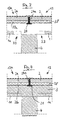
- Fig. 1
- ein Wandelement, ein weiteres Wandelement und ein Dichtungselement in einer seitlichen Schnittansicht,
- Fig. 2
- das Bauteil gemäß Fig. 1 nach dem Einbringen von Ortbeton,
- Fig. 3
- ein Wandelement, ein weiteres Wandelement, eine Innenwand und ein Dichtungselement in einer seitlichen Schnittansicht,
- Fig. 4
- das Bauteil gemäß Fig. 3 nach dem Einbringen von Ortbeton,
- Fig. 5
- den Randbereich einer Vakuumisolationsplatte in einer seitlichen Schnittansicht und
- Fig. 6
- zwei nebeneinanderliegende Vakuumisolationsplatten in einer Teilansicht von vorne.
- Fig. 1
- a wall element, a further wall element and a sealing element in a lateral sectional view,
- Fig. 2
- the component according to FIG. 1 after introduction of in-situ concrete,
- Fig. 3
- a wall element, a further wall element, an inner wall and a sealing element in a lateral sectional view,
- Fig. 4
- the component according to FIG. 3 after the introduction of in-situ concrete,
- Fig. 5
- the edge region of a vacuum insulation plate in a side sectional view and
- Fig. 6
- two juxtaposed vacuum insulation panels in a partial view from the front.
Das in Fig. 1 gezeigte Wandelement 13 umfaßt eine Vakuumisolationsplatte (VIP) 38, ein äußeres Betonfertigteil 2 und ein inneres Betonfertigteil 1, die durch Anker 14, nämlich GFK-Anker, miteinander verbunden sind. Das innere Betonfertigteil 1 ist von der Vakuumisolationsplatte 38 beabstandet. Bei der Herstellung der Wand wird der Zwischenraum zwischen der Vakuumisolationsplatte 38 und dem inneren Betonfertigteil 1 durch Ortbeton 3 gefüllt.The
Die Anker 14 sind vorzugsweise aus einem Material mit einer geringen Wärmeleitfähigkeit und/oder mit einer hohen mechanischen Festigkeit hergestellt. Besonders geeignet sind GFK-Werkstoffe und kohlefaserverstärkter Kunststoff. Die Anker 14 können von jeweils einer Hülse 92 umgeben sein. Ferner können im Bereich der Anker 14 beidseits der Vakuumisolationsplatten 38 Abdeckscheiben 93 vorgesehen sein, die eine mittige Öffnung zum Durchtritt eines Ankers 14 aufweisen, die sich an die Enden der Hülsen 92 nach außen anschließen und die die an die Hülsen 92 anschließenden Bereiche der Vakuumisolationsplatten 38 abdecken. Die Hülsen 92 und/oder die Abdeckscheiben 93 dienen zur Wärmeisolation der Anker 14. Sie tragen dazu bei, daß die Anker 14 keine Wärmebrücken bilden.The
Das innere Betonfertigteil 1 ist kürzer als das äußere Betonfertigteil 2. Die Vakuumisolationsplatte 38 ist genauso lang wie das äußere Betonfertigteil 2. Die Endflächen des äußeren Betonfertigteils 2 und der Vakuumisolationsplatte 38 fluchten also miteinander.The inner precast
Das in Fig. 1 gezeigte Wandelement 13 soll mit einem weiteren Wandelement 13a zu einer rechtwinkligen Ecke zusammengebaut werden. Das weitere Wandelement 13a umfaßt eine Vakuumisolationsplatte 38a, ein äußeres Betonfertigteil 2a und ein inneres Betonfertigteil 1a, die durch Anker 14 miteinander verbunden sind. Sowohl das äußere Betonfertigteil 2 als auch das innere Betonfertigteil 1 liegen unmittelbar an der Vakuumisolationsplatte 38 an. Die Stärke des äußeren Betonfertigteils 2a des weiteren Wandelements 13a stimmt mit der Stärke des äußeren Betonfertigteils 2 des Wandelements 13 überein. Die Stärke des inneren Betonfertigteils 1a des weiteren Wandelements 13a ist größer, und zwar um das zwei- bis dreifache größer, als die Stärke des inneren Betonfertigteils 1 des Wandelements 13.The
Das äußere Betonfertigteil 2a des weiteren Bauelements 13a überragt das äußere Ende der Vakuumisolationsplatte 38a um das Maß der Stärke des äußeren Betonfertigteils 2 und der Vakuumisolationsplatte 38 des Wandelements 13, so daß die miteinander fluchtenden Endflächen des äußeren Betonfertigteils 2 und der Vakuumisolationsplatte 38 an dem überragenden Teil des äußeren Betonfertigteils 2a anliegen. Die Stirnflächen des äußeren Betonfertigteils 2 und der Vakuumisolationsplatte 38 sind gegen die überragende Seitenfläche des äußeren Betonfertigteils 2a durch ein Compriband 24c abgedichtet.The outer precast
Die Vakuumisolationsplatte 38a überragt das innere Betonfertigteil 1 a des weiteren Wandelements 13a um das Maß des Abstandes zwischen der Vakuumisolationsplatte 38 und dem inneren Betonfertigteil 1 des Wandelements 13. Die äußere Stirnfläche der Vakuumisolationsplatte 38a liegt an einer Seitenfläche der Vakuumisolationsplatte 38 an, wobei die Außenfläche der Vakuumisolationsplatte 38a mit der Stirnfläche der Vakuumisolationsplatte 38 fluchtet. Der Eckbereich der Vakuumisolationsplatten 38, 38a ist durch ein Dichtungselement 20 abgedichtet. Das Dichtungselement 20 besteht aus diffusionsdichten Dichtungsbändern.The
Damit das Dichtungselement 20 an der Fig. 1 gezeigten Stelle positioniert werden kann, ist das innere Betonfertigteil 1 des Wandelements 13 kürzer als das äußere Betonfertigteil 2, derart, daß beim Zusammenbau mit dem weiteren Wandelement 13a das Dichtungselement 20 einbringbar ist. Das von der Vakuumisolationsplatte 38 beabstandete innere Betonfertigteil 1 ist um ein solches Maß kürzer als das äußere Betonfertigteil 2, daß eine Lücke 33 entsteht, durch die hindurch das Dichtungselement 20 einbringbar ist. Der Abstand zwischen der äußeren Stirnfläche des inneren Betonfertigteils 1 von der Stirnfläche des äußeren Betonfertigteils 2 ist größer als die kombinierte Stärke der Vakuumisolationsplatte 38a und des inneren Betonfertigteils 1 a.So that the sealing
Bei der Herstellung der in Fig. 2 gezeigten Ecke werden der Zwischenraum zwischen der Vakuumisolationsplatte 38 und dem inneren Betonfertigteil 1 sowie die Lücke 33 mit Ortbeton 3 gefüllt.In the production of the corner shown in Fig. 2, the gap between the
Das in Fig. 3 gezeigte Bauteil besteht aus dem in Fig. 1 und 2 gezeigten Wandelement 13 und einem weiteren Wandelement 13a, das zu dem Wandelement 13 symmetrisch ausgebildet ist, sowie einer Innenwand 4. Die Innenwand 4 ist als Betonfertigteil ausgebildet.The component shown in Fig. 3 consists of the
Zwischen den Stirnflächen der äußeren Betonfertigteile 2, 2a und der Vakuumisolationsplatten 38, 38a sind Compribänder 24a zum Verschließen der Fuge vorgesehen. Die unteren Enden der Compribänder 24a fluchten mit den unteren Endflächen der Vakuumisolationsplatten 38, 38a. Sie sind durch ein Dichtungselement 20 abgedeckt, das durch ein diffusionsoffenes Dichtungsband gebildet wird. Das Dichtungselement 20 kann durch eine der Lücken 33 hindurch positioniert werden. Danach werden die Lücken 33 und der Zwischenraum zwischen den inneren Betonfertigteilen 1, 1 a und den Vakuumisolationsplatten 38, 38a durch Ortbeton 3 gefüllt.Between the end faces of the outer precast
Bei den Compribändern 24, 24a handelt es sich vorzugsweise um vorkomprimierte Fugendichtbänder aus offenzelligem Kunststoffschaum, insbesondere Polyurethan-Weichschaum, mit Polymerimprägnat oder mit einem Imprägnat auf Acrylatbasis.
Fig. 5 zeigt den Randbereich einer Vakuumisolationsplatte 38, die eine Vakuumdämmplatte 94 umfaßt, die auf beiden Seiten von jeweils einer Platte 95 aus Polyurethanschaum oder aus massivem Polyurethan umgeben ist. Die Außenseiten der Platten 95 sind von einer diffusionsdichten und gasdichten Umhüllung 98 abgedeckt. Die Außenkanten der Vakuumdämmplatte 94 sind von einem Compriband 96 umgeben, das seinerseits von einem Butylband 97 umgeben ist. Das Butylband 97 übergreift das Compriband 96 und die äußeren Enden der Platten 95 einschließlich der Umhüllungen 98, mit denen es verbunden, insbesondere verklebt, ist. Das Compriband 96 ist gewölbt. Seine Stärke nimmt von der Mitte nach außen hin ab. Wenn benachbarte Vakuumisolationsplatten 38, 38' aneinandergelegt werden, werden die zugehörigen Compribänder 96 zusammengedrückt, wodurch ein Fugendichtschluß nebeneinanderliegender Vakuumisolationsplatten 38, 38' gewährleistet werden kann.Fig. 5 shows the edge region of a
In Fig. 6 sind Teilbereiche von zwei nebeneinanderliegenden Vakuumisolationsplatten 38, 38' dargestellt. Im Bereich der Ankerdurchführung, also im Bereich einer Hülse 92 für einen Anker 14, weisen die Vakuumisolationsplatten 38, 38' jeweils Aussparungen 99, 99' auf, die einander gegenüberliegen. Der Bereich zwischen den Aussparungen 99, 99' und der Hülse 92 wird ebenfalls durch die Compribänder 96 gefüllt.In Fig. 6 partial areas of two juxtaposed
Claims (3)
dadurch gekennzeichnet,
daß ein Betonfertigteil (1) von der Vakuumisolationsplatte (38) beabstandet ist und daß dieses Betonfertigteil (1) kürzer ist als das andere Betonfertigteil (2), derart, daß bei Zusammenbau mit einem weiteren Bauelement (13a, 4) ein Dichtungselement (20) einbringbar ist.Wall element comprising a vacuum insulation panel (38), an outer prefabricated concrete part (2) and an inner precast concrete part (1) which are interconnected by anchors (14),
characterized,
in that a precast concrete part (1) is spaced from the vacuum insulation panel (38) and that this prefabricated concrete part (1) is shorter than the other precast concrete part (2) such that when assembled with a further structural element (13a, 4) a sealing element (20) can be introduced.
Applications Claiming Priority (1)
| Application Number | Priority Date | Filing Date | Title |
|---|---|---|---|
| DE102005027972A DE102005027972A1 (en) | 2005-06-16 | 2005-06-16 | wall element |
Publications (2)
| Publication Number | Publication Date |
|---|---|
| EP1734197A1 true EP1734197A1 (en) | 2006-12-20 |
| EP1734197B1 EP1734197B1 (en) | 2011-09-14 |
Family
ID=37057221
Family Applications (1)
| Application Number | Title | Priority Date | Filing Date |
|---|---|---|---|
| EP06012117A Active EP1734197B1 (en) | 2005-06-16 | 2006-06-13 | Wall element comprising vacuum insulation panel arranged between two prefabricated concrete parts |
Country Status (3)
| Country | Link |
|---|---|
| EP (1) | EP1734197B1 (en) |
| AT (1) | ATE524622T1 (en) |
| DE (1) | DE102005027972A1 (en) |
Cited By (1)
| Publication number | Priority date | Publication date | Assignee | Title |
|---|---|---|---|---|
| CN112459307A (en) * | 2020-11-28 | 2021-03-09 | 青岛科瑞新型环保材料集团有限公司 | Construction method of prefabricated heat-preservation-structure integrated wall external formwork |
Families Citing this family (1)
| Publication number | Priority date | Publication date | Assignee | Title |
|---|---|---|---|---|
| CN110258874B (en) * | 2019-06-27 | 2021-11-12 | 安徽恒兴新型建材有限公司 | Rock wool outer wall external thermal insulation structure for dry-hanging curtain wall |
Citations (5)
| Publication number | Priority date | Publication date | Assignee | Title |
|---|---|---|---|---|
| DE9305488U1 (en) * | 1993-04-10 | 1993-11-25 | Hofmann Hansjoerg | Lightweight concrete wall panels with an open cross-section and integrated thermal insulation |
| EP0837194A1 (en) * | 1996-10-17 | 1998-04-22 | Lösch GmbH Betonwerke | Wall element |
| DE19826921A1 (en) * | 1998-06-17 | 2000-01-05 | Eckehard Erndwein | Wall component for house with concrete outer and inner shells |
| EP1500752A2 (en) * | 2003-07-22 | 2005-01-26 | Sto Ag | Insulating element and heat insulation system |
| EP1544367A2 (en) * | 2003-12-15 | 2005-06-22 | Va-Q-tec AG | Laminated heat insulating panel |
-
2005
- 2005-06-16 DE DE102005027972A patent/DE102005027972A1/en not_active Withdrawn
-
2006
- 2006-06-13 EP EP06012117A patent/EP1734197B1/en active Active
- 2006-06-13 AT AT06012117T patent/ATE524622T1/en active
Patent Citations (5)
| Publication number | Priority date | Publication date | Assignee | Title |
|---|---|---|---|---|
| DE9305488U1 (en) * | 1993-04-10 | 1993-11-25 | Hofmann Hansjoerg | Lightweight concrete wall panels with an open cross-section and integrated thermal insulation |
| EP0837194A1 (en) * | 1996-10-17 | 1998-04-22 | Lösch GmbH Betonwerke | Wall element |
| DE19826921A1 (en) * | 1998-06-17 | 2000-01-05 | Eckehard Erndwein | Wall component for house with concrete outer and inner shells |
| EP1500752A2 (en) * | 2003-07-22 | 2005-01-26 | Sto Ag | Insulating element and heat insulation system |
| EP1544367A2 (en) * | 2003-12-15 | 2005-06-22 | Va-Q-tec AG | Laminated heat insulating panel |
Cited By (1)
| Publication number | Priority date | Publication date | Assignee | Title |
|---|---|---|---|---|
| CN112459307A (en) * | 2020-11-28 | 2021-03-09 | 青岛科瑞新型环保材料集团有限公司 | Construction method of prefabricated heat-preservation-structure integrated wall external formwork |
Also Published As
| Publication number | Publication date |
|---|---|
| DE102005027972A1 (en) | 2006-12-21 |
| ATE524622T1 (en) | 2011-09-15 |
| EP1734197B1 (en) | 2011-09-14 |
Similar Documents
| Publication | Publication Date | Title |
|---|---|---|
| EP1544367B1 (en) | Laminated heat insulating panel | |
| DE102008064572A1 (en) | Multilayered thermal insulation board and method for building a thermal insulation facade | |
| DE202004010695U1 (en) | Vacuum insulation panels, to be locked together to form an insulation board, have a gas-tight shrouding of a thermal insulation material around the core held by an adhesive bond | |
| EP2119842B1 (en) | Insulation element and method for producing same | |
| CH631227A5 (en) | Cladding panel | |
| EP1734197B1 (en) | Wall element comprising vacuum insulation panel arranged between two prefabricated concrete parts | |
| EP1734195B1 (en) | Wall element | |
| DE102004050549B4 (en) | Foil-covered vacuum insulation panel and method of making the same | |
| DE10147409A1 (en) | Heat-insulating, load-bearing construction element for buildings comprises a multilayer structure having an outer shell of load-bearing material, an inner shell of load-bearing material, and an insulating layer arranged in between | |
| EP2803807A1 (en) | Door | |
| EP1734196A2 (en) | Penetration element for a wall element | |
| DE10250665A1 (en) | wall system | |
| DE202006008477U1 (en) | Vacuum insulating panel for insulating e.g. refrigerators comprises a plate-like evacuated support body and a two-part gas-tight foil sleeve sealed using heat sealing seals both formed on the outer and inner side | |
| EP2119841A2 (en) | Insulation element and method for producing same | |
| EP1734194A2 (en) | Wall element and associated compensation element | |
| DE102011050632A1 (en) | Honeycomb element for insulation | |
| DE19502201A1 (en) | Vacuum panel stabilised by rigid support wall | |
| DE3308941C2 (en) | Plate-shaped thermal insulation element | |
| AT515886B1 (en) | Insulating board and method for producing an insulating board | |
| WO2010121580A1 (en) | Vacuum insulation element having ceramic cover layers for use in a building shell | |
| DE19809316C2 (en) | Heat insulation body and multilayer body therefor | |
| DE102010018515A1 (en) | Wall element for thermal insulation of building facades, and for use in product line, and hence has outer layer facing outer chamber, where surface is designed to face towards building facade | |
| DE3211077C2 (en) | ||
| EP1734205A1 (en) | Transport anchor for a wall element comprising a vacuum insulation panel arranged between two prefabricated concrete parts | |
| DE202013005599U1 (en) | Wall element, façade element and facade with a vacuum insulation panel |
Legal Events
| Date | Code | Title | Description |
|---|---|---|---|
| PUAI | Public reference made under article 153(3) epc to a published international application that has entered the european phase |
Free format text: ORIGINAL CODE: 0009012 |
|
| AK | Designated contracting states |
Kind code of ref document: A1 Designated state(s): AT BE BG CH CY CZ DE DK EE ES FI FR GB GR HU IE IS IT LI LT LU LV MC NL PL PT RO SE SI SK TR |
|
| AX | Request for extension of the european patent |
Extension state: AL BA HR MK YU |
|
| 17P | Request for examination filed |
Effective date: 20070226 |
|
| 17Q | First examination report despatched |
Effective date: 20070330 |
|
| AKX | Designation fees paid |
Designated state(s): AT BE BG CH CY CZ DE DK EE ES FI FR GB GR HU IE IS IT LI LT LU LV MC NL PL PT RO SE SI SK TR |
|
| AXX | Extension fees paid |
Extension state: AL Payment date: 20060613 Extension state: YU Payment date: 20060613 Extension state: MK Payment date: 20060613 Extension state: BA Payment date: 20060613 Extension state: HR Payment date: 20060613 |
|
| RAX | Requested extension states of the european patent have changed |
Extension state: MK Payment date: 20060613 Extension state: AL Payment date: 20060613 Extension state: BA Payment date: 20060613 Extension state: HR Payment date: 20060613 Extension state: RS Payment date: 20060613 |
|
| GRAP | Despatch of communication of intention to grant a patent |
Free format text: ORIGINAL CODE: EPIDOSNIGR1 |
|
| GRAS | Grant fee paid |
Free format text: ORIGINAL CODE: EPIDOSNIGR3 |
|
| GRAA | (expected) grant |
Free format text: ORIGINAL CODE: 0009210 |
|
| RAP1 | Party data changed (applicant data changed or rights of an application transferred) |
Owner name: VARIOTEC GMBH & CO. KG |
|
| AK | Designated contracting states |
Kind code of ref document: B1 Designated state(s): AT BE BG CH CY CZ DE DK EE ES FI FR GB GR HU IE IS IT LI LT LU LV MC NL PL PT RO SE SI SK TR |
|
| AX | Request for extension of the european patent |
Extension state: AL BA HR MK RS |
|
| REG | Reference to a national code |
Ref country code: CH Ref legal event code: EP Ref country code: CH Ref legal event code: NV Representative=s name: BOVARD AG |
|
| REG | Reference to a national code |
Ref country code: IE Ref legal event code: FG4D Free format text: LANGUAGE OF EP DOCUMENT: GERMAN |
|
| REG | Reference to a national code |
Ref country code: DE Ref legal event code: R096 Ref document number: 502006010147 Country of ref document: DE Effective date: 20111201 |
|
| REG | Reference to a national code |
Ref country code: NL Ref legal event code: VDEP Effective date: 20110914 |
|
| PG25 | Lapsed in a contracting state [announced via postgrant information from national office to epo] |
Ref country code: LT Free format text: LAPSE BECAUSE OF FAILURE TO SUBMIT A TRANSLATION OF THE DESCRIPTION OR TO PAY THE FEE WITHIN THE PRESCRIBED TIME-LIMIT Effective date: 20110914 Ref country code: FI Free format text: LAPSE BECAUSE OF FAILURE TO SUBMIT A TRANSLATION OF THE DESCRIPTION OR TO PAY THE FEE WITHIN THE PRESCRIBED TIME-LIMIT Effective date: 20110914 Ref country code: SE Free format text: LAPSE BECAUSE OF FAILURE TO SUBMIT A TRANSLATION OF THE DESCRIPTION OR TO PAY THE FEE WITHIN THE PRESCRIBED TIME-LIMIT Effective date: 20110914 |
|
| LTIE | Lt: invalidation of european patent or patent extension |
Effective date: 20110914 |
|
| PG25 | Lapsed in a contracting state [announced via postgrant information from national office to epo] |
Ref country code: CY Free format text: LAPSE BECAUSE OF FAILURE TO SUBMIT A TRANSLATION OF THE DESCRIPTION OR TO PAY THE FEE WITHIN THE PRESCRIBED TIME-LIMIT Effective date: 20110914 Ref country code: LV Free format text: LAPSE BECAUSE OF FAILURE TO SUBMIT A TRANSLATION OF THE DESCRIPTION OR TO PAY THE FEE WITHIN THE PRESCRIBED TIME-LIMIT Effective date: 20110914 Ref country code: GR Free format text: LAPSE BECAUSE OF FAILURE TO SUBMIT A TRANSLATION OF THE DESCRIPTION OR TO PAY THE FEE WITHIN THE PRESCRIBED TIME-LIMIT Effective date: 20111215 Ref country code: SI Free format text: LAPSE BECAUSE OF FAILURE TO SUBMIT A TRANSLATION OF THE DESCRIPTION OR TO PAY THE FEE WITHIN THE PRESCRIBED TIME-LIMIT Effective date: 20110914 |
|
| REG | Reference to a national code |
Ref country code: IE Ref legal event code: FD4D |
|
| PG25 | Lapsed in a contracting state [announced via postgrant information from national office to epo] |
Ref country code: SK Free format text: LAPSE BECAUSE OF FAILURE TO SUBMIT A TRANSLATION OF THE DESCRIPTION OR TO PAY THE FEE WITHIN THE PRESCRIBED TIME-LIMIT Effective date: 20110914 Ref country code: IS Free format text: LAPSE BECAUSE OF FAILURE TO SUBMIT A TRANSLATION OF THE DESCRIPTION OR TO PAY THE FEE WITHIN THE PRESCRIBED TIME-LIMIT Effective date: 20120114 Ref country code: CZ Free format text: LAPSE BECAUSE OF FAILURE TO SUBMIT A TRANSLATION OF THE DESCRIPTION OR TO PAY THE FEE WITHIN THE PRESCRIBED TIME-LIMIT Effective date: 20110914 Ref country code: IE Free format text: LAPSE BECAUSE OF FAILURE TO SUBMIT A TRANSLATION OF THE DESCRIPTION OR TO PAY THE FEE WITHIN THE PRESCRIBED TIME-LIMIT Effective date: 20110914 |
|
| PG25 | Lapsed in a contracting state [announced via postgrant information from national office to epo] |
Ref country code: RO Free format text: LAPSE BECAUSE OF FAILURE TO SUBMIT A TRANSLATION OF THE DESCRIPTION OR TO PAY THE FEE WITHIN THE PRESCRIBED TIME-LIMIT Effective date: 20110914 Ref country code: EE Free format text: LAPSE BECAUSE OF FAILURE TO SUBMIT A TRANSLATION OF THE DESCRIPTION OR TO PAY THE FEE WITHIN THE PRESCRIBED TIME-LIMIT Effective date: 20110914 Ref country code: IT Free format text: LAPSE BECAUSE OF FAILURE TO SUBMIT A TRANSLATION OF THE DESCRIPTION OR TO PAY THE FEE WITHIN THE PRESCRIBED TIME-LIMIT Effective date: 20110914 Ref country code: PT Free format text: LAPSE BECAUSE OF FAILURE TO SUBMIT A TRANSLATION OF THE DESCRIPTION OR TO PAY THE FEE WITHIN THE PRESCRIBED TIME-LIMIT Effective date: 20120116 Ref country code: PL Free format text: LAPSE BECAUSE OF FAILURE TO SUBMIT A TRANSLATION OF THE DESCRIPTION OR TO PAY THE FEE WITHIN THE PRESCRIBED TIME-LIMIT Effective date: 20110914 Ref country code: NL Free format text: LAPSE BECAUSE OF FAILURE TO SUBMIT A TRANSLATION OF THE DESCRIPTION OR TO PAY THE FEE WITHIN THE PRESCRIBED TIME-LIMIT Effective date: 20110914 |
|
| PLBE | No opposition filed within time limit |
Free format text: ORIGINAL CODE: 0009261 |
|
| STAA | Information on the status of an ep patent application or granted ep patent |
Free format text: STATUS: NO OPPOSITION FILED WITHIN TIME LIMIT |
|
| PG25 | Lapsed in a contracting state [announced via postgrant information from national office to epo] |
Ref country code: DK Free format text: LAPSE BECAUSE OF FAILURE TO SUBMIT A TRANSLATION OF THE DESCRIPTION OR TO PAY THE FEE WITHIN THE PRESCRIBED TIME-LIMIT Effective date: 20110914 |
|
| 26N | No opposition filed |
Effective date: 20120615 |
|
| REG | Reference to a national code |
Ref country code: DE Ref legal event code: R097 Ref document number: 502006010147 Country of ref document: DE Effective date: 20120615 |
|
| BERE | Be: lapsed |
Owner name: VARIOTEC G.M.B.H. & CO. KG Effective date: 20120630 |
|
| PG25 | Lapsed in a contracting state [announced via postgrant information from national office to epo] |
Ref country code: MC Free format text: LAPSE BECAUSE OF NON-PAYMENT OF DUE FEES Effective date: 20120630 |
|
| REG | Reference to a national code |
Ref country code: CH Ref legal event code: PL |
|
| REG | Reference to a national code |
Ref country code: CH Ref legal event code: PL |
|
| GBPC | Gb: european patent ceased through non-payment of renewal fee |
Effective date: 20120613 |
|
| REG | Reference to a national code |
Ref country code: FR Ref legal event code: ST Effective date: 20130228 |
|
| PG25 | Lapsed in a contracting state [announced via postgrant information from national office to epo] |
Ref country code: GB Free format text: LAPSE BECAUSE OF NON-PAYMENT OF DUE FEES Effective date: 20120613 Ref country code: BE Free format text: LAPSE BECAUSE OF NON-PAYMENT OF DUE FEES Effective date: 20120630 Ref country code: DE Free format text: LAPSE BECAUSE OF NON-PAYMENT OF DUE FEES Effective date: 20130101 Ref country code: LI Free format text: LAPSE BECAUSE OF NON-PAYMENT OF DUE FEES Effective date: 20120630 Ref country code: ES Free format text: LAPSE BECAUSE OF FAILURE TO SUBMIT A TRANSLATION OF THE DESCRIPTION OR TO PAY THE FEE WITHIN THE PRESCRIBED TIME-LIMIT Effective date: 20111225 Ref country code: FR Free format text: LAPSE BECAUSE OF NON-PAYMENT OF DUE FEES Effective date: 20120702 Ref country code: CH Free format text: LAPSE BECAUSE OF NON-PAYMENT OF DUE FEES Effective date: 20120630 |
|
| REG | Reference to a national code |
Ref country code: DE Ref legal event code: R119 Ref document number: 502006010147 Country of ref document: DE Effective date: 20130101 |
|
| PG25 | Lapsed in a contracting state [announced via postgrant information from national office to epo] |
Ref country code: BG Free format text: LAPSE BECAUSE OF FAILURE TO SUBMIT A TRANSLATION OF THE DESCRIPTION OR TO PAY THE FEE WITHIN THE PRESCRIBED TIME-LIMIT Effective date: 20111214 |
|
| REG | Reference to a national code |
Ref country code: AT Ref legal event code: MM01 Ref document number: 524622 Country of ref document: AT Kind code of ref document: T Effective date: 20120613 |
|
| PG25 | Lapsed in a contracting state [announced via postgrant information from national office to epo] |
Ref country code: AT Free format text: LAPSE BECAUSE OF NON-PAYMENT OF DUE FEES Effective date: 20120613 |
|
| PG25 | Lapsed in a contracting state [announced via postgrant information from national office to epo] |
Ref country code: TR Free format text: LAPSE BECAUSE OF FAILURE TO SUBMIT A TRANSLATION OF THE DESCRIPTION OR TO PAY THE FEE WITHIN THE PRESCRIBED TIME-LIMIT Effective date: 20110914 |
|
| PG25 | Lapsed in a contracting state [announced via postgrant information from national office to epo] |
Ref country code: LU Free format text: LAPSE BECAUSE OF NON-PAYMENT OF DUE FEES Effective date: 20120613 |
|
| PG25 | Lapsed in a contracting state [announced via postgrant information from national office to epo] |
Ref country code: HU Free format text: LAPSE BECAUSE OF FAILURE TO SUBMIT A TRANSLATION OF THE DESCRIPTION OR TO PAY THE FEE WITHIN THE PRESCRIBED TIME-LIMIT Effective date: 20060613 |