EP1734098A1 - A process of production of lower olefins and aromaticas - Google Patents
A process of production of lower olefins and aromaticas Download PDFInfo
- Publication number
- EP1734098A1 EP1734098A1 EP05714812A EP05714812A EP1734098A1 EP 1734098 A1 EP1734098 A1 EP 1734098A1 EP 05714812 A EP05714812 A EP 05714812A EP 05714812 A EP05714812 A EP 05714812A EP 1734098 A1 EP1734098 A1 EP 1734098A1
- Authority
- EP
- European Patent Office
- Prior art keywords
- reaction
- reaction zone
- naphtha
- catalytic cracking
- catalyst
- Prior art date
- Legal status (The legal status is an assumption and is not a legal conclusion. Google has not performed a legal analysis and makes no representation as to the accuracy of the status listed.)
- Ceased
Links
Images



Classifications
-
- C—CHEMISTRY; METALLURGY
- C10—PETROLEUM, GAS OR COKE INDUSTRIES; TECHNICAL GASES CONTAINING CARBON MONOXIDE; FUELS; LUBRICANTS; PEAT
- C10G—CRACKING HYDROCARBON OILS; PRODUCTION OF LIQUID HYDROCARBON MIXTURES, e.g. BY DESTRUCTIVE HYDROGENATION, OLIGOMERISATION, POLYMERISATION; RECOVERY OF HYDROCARBON OILS FROM OIL-SHALE, OIL-SAND, OR GASES; REFINING MIXTURES MAINLY CONSISTING OF HYDROCARBONS; REFORMING OF NAPHTHA; MINERAL WAXES
- C10G11/00—Catalytic cracking, in the absence of hydrogen, of hydrocarbon oils
- C10G11/14—Catalytic cracking, in the absence of hydrogen, of hydrocarbon oils with preheated moving solid catalysts
- C10G11/18—Catalytic cracking, in the absence of hydrogen, of hydrocarbon oils with preheated moving solid catalysts according to the "fluidised-bed" technique
-
- C—CHEMISTRY; METALLURGY
- C10—PETROLEUM, GAS OR COKE INDUSTRIES; TECHNICAL GASES CONTAINING CARBON MONOXIDE; FUELS; LUBRICANTS; PEAT
- C10G—CRACKING HYDROCARBON OILS; PRODUCTION OF LIQUID HYDROCARBON MIXTURES, e.g. BY DESTRUCTIVE HYDROGENATION, OLIGOMERISATION, POLYMERISATION; RECOVERY OF HYDROCARBON OILS FROM OIL-SHALE, OIL-SAND, OR GASES; REFINING MIXTURES MAINLY CONSISTING OF HYDROCARBONS; REFORMING OF NAPHTHA; MINERAL WAXES
- C10G69/00—Treatment of hydrocarbon oils by at least one hydrotreatment process and at least one other conversion process
- C10G69/02—Treatment of hydrocarbon oils by at least one hydrotreatment process and at least one other conversion process plural serial stages only
- C10G69/04—Treatment of hydrocarbon oils by at least one hydrotreatment process and at least one other conversion process plural serial stages only including at least one step of catalytic cracking in the absence of hydrogen
-
- C—CHEMISTRY; METALLURGY
- C07—ORGANIC CHEMISTRY
- C07C—ACYCLIC OR CARBOCYCLIC COMPOUNDS
- C07C4/00—Preparation of hydrocarbons from hydrocarbons containing a larger number of carbon atoms
- C07C4/02—Preparation of hydrocarbons from hydrocarbons containing a larger number of carbon atoms by cracking a single hydrocarbon or a mixture of individually defined hydrocarbons or a normally gaseous hydrocarbon fraction
- C07C4/06—Catalytic processes
-
- C—CHEMISTRY; METALLURGY
- C07—ORGANIC CHEMISTRY
- C07C—ACYCLIC OR CARBOCYCLIC COMPOUNDS
- C07C5/00—Preparation of hydrocarbons from hydrocarbons containing the same number of carbon atoms
- C07C5/02—Preparation of hydrocarbons from hydrocarbons containing the same number of carbon atoms by hydrogenation
- C07C5/03—Preparation of hydrocarbons from hydrocarbons containing the same number of carbon atoms by hydrogenation of non-aromatic carbon-to-carbon double bonds
- C07C5/05—Partial hydrogenation
-
- C—CHEMISTRY; METALLURGY
- C07—ORGANIC CHEMISTRY
- C07C—ACYCLIC OR CARBOCYCLIC COMPOUNDS
- C07C5/00—Preparation of hydrocarbons from hydrocarbons containing the same number of carbon atoms
- C07C5/02—Preparation of hydrocarbons from hydrocarbons containing the same number of carbon atoms by hydrogenation
- C07C5/10—Preparation of hydrocarbons from hydrocarbons containing the same number of carbon atoms by hydrogenation of aromatic six-membered rings
- C07C5/11—Partial hydrogenation
-
- C—CHEMISTRY; METALLURGY
- C10—PETROLEUM, GAS OR COKE INDUSTRIES; TECHNICAL GASES CONTAINING CARBON MONOXIDE; FUELS; LUBRICANTS; PEAT
- C10G—CRACKING HYDROCARBON OILS; PRODUCTION OF LIQUID HYDROCARBON MIXTURES, e.g. BY DESTRUCTIVE HYDROGENATION, OLIGOMERISATION, POLYMERISATION; RECOVERY OF HYDROCARBON OILS FROM OIL-SHALE, OIL-SAND, OR GASES; REFINING MIXTURES MAINLY CONSISTING OF HYDROCARBONS; REFORMING OF NAPHTHA; MINERAL WAXES
- C10G69/00—Treatment of hydrocarbon oils by at least one hydrotreatment process and at least one other conversion process
- C10G69/02—Treatment of hydrocarbon oils by at least one hydrotreatment process and at least one other conversion process plural serial stages only
-
- C—CHEMISTRY; METALLURGY
- C10—PETROLEUM, GAS OR COKE INDUSTRIES; TECHNICAL GASES CONTAINING CARBON MONOXIDE; FUELS; LUBRICANTS; PEAT
- C10G—CRACKING HYDROCARBON OILS; PRODUCTION OF LIQUID HYDROCARBON MIXTURES, e.g. BY DESTRUCTIVE HYDROGENATION, OLIGOMERISATION, POLYMERISATION; RECOVERY OF HYDROCARBON OILS FROM OIL-SHALE, OIL-SAND, OR GASES; REFINING MIXTURES MAINLY CONSISTING OF HYDROCARBONS; REFORMING OF NAPHTHA; MINERAL WAXES
- C10G69/00—Treatment of hydrocarbon oils by at least one hydrotreatment process and at least one other conversion process
- C10G69/02—Treatment of hydrocarbon oils by at least one hydrotreatment process and at least one other conversion process plural serial stages only
- C10G69/06—Treatment of hydrocarbon oils by at least one hydrotreatment process and at least one other conversion process plural serial stages only including at least one step of thermal cracking in the absence of hydrogen
-
- C—CHEMISTRY; METALLURGY
- C10—PETROLEUM, GAS OR COKE INDUSTRIES; TECHNICAL GASES CONTAINING CARBON MONOXIDE; FUELS; LUBRICANTS; PEAT
- C10G—CRACKING HYDROCARBON OILS; PRODUCTION OF LIQUID HYDROCARBON MIXTURES, e.g. BY DESTRUCTIVE HYDROGENATION, OLIGOMERISATION, POLYMERISATION; RECOVERY OF HYDROCARBON OILS FROM OIL-SHALE, OIL-SAND, OR GASES; REFINING MIXTURES MAINLY CONSISTING OF HYDROCARBONS; REFORMING OF NAPHTHA; MINERAL WAXES
- C10G69/00—Treatment of hydrocarbon oils by at least one hydrotreatment process and at least one other conversion process
- C10G69/14—Treatment of hydrocarbon oils by at least one hydrotreatment process and at least one other conversion process plural parallel stages only
-
- C—CHEMISTRY; METALLURGY
- C10—PETROLEUM, GAS OR COKE INDUSTRIES; TECHNICAL GASES CONTAINING CARBON MONOXIDE; FUELS; LUBRICANTS; PEAT
- C10G—CRACKING HYDROCARBON OILS; PRODUCTION OF LIQUID HYDROCARBON MIXTURES, e.g. BY DESTRUCTIVE HYDROGENATION, OLIGOMERISATION, POLYMERISATION; RECOVERY OF HYDROCARBON OILS FROM OIL-SHALE, OIL-SAND, OR GASES; REFINING MIXTURES MAINLY CONSISTING OF HYDROCARBONS; REFORMING OF NAPHTHA; MINERAL WAXES
- C10G2300/00—Aspects relating to hydrocarbon processing covered by groups C10G1/00 - C10G99/00
- C10G2300/10—Feedstock materials
- C10G2300/1037—Hydrocarbon fractions
- C10G2300/1044—Heavy gasoline or naphtha having a boiling range of about 100 - 180 °C
-
- C—CHEMISTRY; METALLURGY
- C10—PETROLEUM, GAS OR COKE INDUSTRIES; TECHNICAL GASES CONTAINING CARBON MONOXIDE; FUELS; LUBRICANTS; PEAT
- C10G—CRACKING HYDROCARBON OILS; PRODUCTION OF LIQUID HYDROCARBON MIXTURES, e.g. BY DESTRUCTIVE HYDROGENATION, OLIGOMERISATION, POLYMERISATION; RECOVERY OF HYDROCARBON OILS FROM OIL-SHALE, OIL-SAND, OR GASES; REFINING MIXTURES MAINLY CONSISTING OF HYDROCARBONS; REFORMING OF NAPHTHA; MINERAL WAXES
- C10G2300/00—Aspects relating to hydrocarbon processing covered by groups C10G1/00 - C10G99/00
- C10G2300/10—Feedstock materials
- C10G2300/1037—Hydrocarbon fractions
- C10G2300/1048—Middle distillates
- C10G2300/1055—Diesel having a boiling range of about 230 - 330 °C
-
- C—CHEMISTRY; METALLURGY
- C10—PETROLEUM, GAS OR COKE INDUSTRIES; TECHNICAL GASES CONTAINING CARBON MONOXIDE; FUELS; LUBRICANTS; PEAT
- C10G—CRACKING HYDROCARBON OILS; PRODUCTION OF LIQUID HYDROCARBON MIXTURES, e.g. BY DESTRUCTIVE HYDROGENATION, OLIGOMERISATION, POLYMERISATION; RECOVERY OF HYDROCARBON OILS FROM OIL-SHALE, OIL-SAND, OR GASES; REFINING MIXTURES MAINLY CONSISTING OF HYDROCARBONS; REFORMING OF NAPHTHA; MINERAL WAXES
- C10G2300/00—Aspects relating to hydrocarbon processing covered by groups C10G1/00 - C10G99/00
- C10G2300/10—Feedstock materials
- C10G2300/107—Atmospheric residues having a boiling point of at least about 538 °C
-
- C—CHEMISTRY; METALLURGY
- C10—PETROLEUM, GAS OR COKE INDUSTRIES; TECHNICAL GASES CONTAINING CARBON MONOXIDE; FUELS; LUBRICANTS; PEAT
- C10G—CRACKING HYDROCARBON OILS; PRODUCTION OF LIQUID HYDROCARBON MIXTURES, e.g. BY DESTRUCTIVE HYDROGENATION, OLIGOMERISATION, POLYMERISATION; RECOVERY OF HYDROCARBON OILS FROM OIL-SHALE, OIL-SAND, OR GASES; REFINING MIXTURES MAINLY CONSISTING OF HYDROCARBONS; REFORMING OF NAPHTHA; MINERAL WAXES
- C10G2300/00—Aspects relating to hydrocarbon processing covered by groups C10G1/00 - C10G99/00
- C10G2300/10—Feedstock materials
- C10G2300/1074—Vacuum distillates
-
- C—CHEMISTRY; METALLURGY
- C10—PETROLEUM, GAS OR COKE INDUSTRIES; TECHNICAL GASES CONTAINING CARBON MONOXIDE; FUELS; LUBRICANTS; PEAT
- C10G—CRACKING HYDROCARBON OILS; PRODUCTION OF LIQUID HYDROCARBON MIXTURES, e.g. BY DESTRUCTIVE HYDROGENATION, OLIGOMERISATION, POLYMERISATION; RECOVERY OF HYDROCARBON OILS FROM OIL-SHALE, OIL-SAND, OR GASES; REFINING MIXTURES MAINLY CONSISTING OF HYDROCARBONS; REFORMING OF NAPHTHA; MINERAL WAXES
- C10G2300/00—Aspects relating to hydrocarbon processing covered by groups C10G1/00 - C10G99/00
- C10G2300/10—Feedstock materials
- C10G2300/1077—Vacuum residues
-
- C—CHEMISTRY; METALLURGY
- C10—PETROLEUM, GAS OR COKE INDUSTRIES; TECHNICAL GASES CONTAINING CARBON MONOXIDE; FUELS; LUBRICANTS; PEAT
- C10G—CRACKING HYDROCARBON OILS; PRODUCTION OF LIQUID HYDROCARBON MIXTURES, e.g. BY DESTRUCTIVE HYDROGENATION, OLIGOMERISATION, POLYMERISATION; RECOVERY OF HYDROCARBON OILS FROM OIL-SHALE, OIL-SAND, OR GASES; REFINING MIXTURES MAINLY CONSISTING OF HYDROCARBONS; REFORMING OF NAPHTHA; MINERAL WAXES
- C10G2300/00—Aspects relating to hydrocarbon processing covered by groups C10G1/00 - C10G99/00
- C10G2300/20—Characteristics of the feedstock or the products
- C10G2300/30—Physical properties of feedstocks or products
- C10G2300/301—Boiling range
-
- C—CHEMISTRY; METALLURGY
- C10—PETROLEUM, GAS OR COKE INDUSTRIES; TECHNICAL GASES CONTAINING CARBON MONOXIDE; FUELS; LUBRICANTS; PEAT
- C10G—CRACKING HYDROCARBON OILS; PRODUCTION OF LIQUID HYDROCARBON MIXTURES, e.g. BY DESTRUCTIVE HYDROGENATION, OLIGOMERISATION, POLYMERISATION; RECOVERY OF HYDROCARBON OILS FROM OIL-SHALE, OIL-SAND, OR GASES; REFINING MIXTURES MAINLY CONSISTING OF HYDROCARBONS; REFORMING OF NAPHTHA; MINERAL WAXES
- C10G2300/00—Aspects relating to hydrocarbon processing covered by groups C10G1/00 - C10G99/00
- C10G2300/40—Characteristics of the process deviating from typical ways of processing
- C10G2300/4006—Temperature
-
- C—CHEMISTRY; METALLURGY
- C10—PETROLEUM, GAS OR COKE INDUSTRIES; TECHNICAL GASES CONTAINING CARBON MONOXIDE; FUELS; LUBRICANTS; PEAT
- C10G—CRACKING HYDROCARBON OILS; PRODUCTION OF LIQUID HYDROCARBON MIXTURES, e.g. BY DESTRUCTIVE HYDROGENATION, OLIGOMERISATION, POLYMERISATION; RECOVERY OF HYDROCARBON OILS FROM OIL-SHALE, OIL-SAND, OR GASES; REFINING MIXTURES MAINLY CONSISTING OF HYDROCARBONS; REFORMING OF NAPHTHA; MINERAL WAXES
- C10G2300/00—Aspects relating to hydrocarbon processing covered by groups C10G1/00 - C10G99/00
- C10G2300/40—Characteristics of the process deviating from typical ways of processing
- C10G2300/4018—Spatial velocity, e.g. LHSV, WHSV
-
- C—CHEMISTRY; METALLURGY
- C10—PETROLEUM, GAS OR COKE INDUSTRIES; TECHNICAL GASES CONTAINING CARBON MONOXIDE; FUELS; LUBRICANTS; PEAT
- C10G—CRACKING HYDROCARBON OILS; PRODUCTION OF LIQUID HYDROCARBON MIXTURES, e.g. BY DESTRUCTIVE HYDROGENATION, OLIGOMERISATION, POLYMERISATION; RECOVERY OF HYDROCARBON OILS FROM OIL-SHALE, OIL-SAND, OR GASES; REFINING MIXTURES MAINLY CONSISTING OF HYDROCARBONS; REFORMING OF NAPHTHA; MINERAL WAXES
- C10G2300/00—Aspects relating to hydrocarbon processing covered by groups C10G1/00 - C10G99/00
- C10G2300/40—Characteristics of the process deviating from typical ways of processing
- C10G2300/4093—Catalyst stripping
-
- C—CHEMISTRY; METALLURGY
- C10—PETROLEUM, GAS OR COKE INDUSTRIES; TECHNICAL GASES CONTAINING CARBON MONOXIDE; FUELS; LUBRICANTS; PEAT
- C10G—CRACKING HYDROCARBON OILS; PRODUCTION OF LIQUID HYDROCARBON MIXTURES, e.g. BY DESTRUCTIVE HYDROGENATION, OLIGOMERISATION, POLYMERISATION; RECOVERY OF HYDROCARBON OILS FROM OIL-SHALE, OIL-SAND, OR GASES; REFINING MIXTURES MAINLY CONSISTING OF HYDROCARBONS; REFORMING OF NAPHTHA; MINERAL WAXES
- C10G2300/00—Aspects relating to hydrocarbon processing covered by groups C10G1/00 - C10G99/00
- C10G2300/40—Characteristics of the process deviating from typical ways of processing
- C10G2300/44—Solvents
-
- C—CHEMISTRY; METALLURGY
- C10—PETROLEUM, GAS OR COKE INDUSTRIES; TECHNICAL GASES CONTAINING CARBON MONOXIDE; FUELS; LUBRICANTS; PEAT
- C10G—CRACKING HYDROCARBON OILS; PRODUCTION OF LIQUID HYDROCARBON MIXTURES, e.g. BY DESTRUCTIVE HYDROGENATION, OLIGOMERISATION, POLYMERISATION; RECOVERY OF HYDROCARBON OILS FROM OIL-SHALE, OIL-SAND, OR GASES; REFINING MIXTURES MAINLY CONSISTING OF HYDROCARBONS; REFORMING OF NAPHTHA; MINERAL WAXES
- C10G2300/00—Aspects relating to hydrocarbon processing covered by groups C10G1/00 - C10G99/00
- C10G2300/80—Additives
- C10G2300/805—Water
- C10G2300/807—Steam
-
- C—CHEMISTRY; METALLURGY
- C10—PETROLEUM, GAS OR COKE INDUSTRIES; TECHNICAL GASES CONTAINING CARBON MONOXIDE; FUELS; LUBRICANTS; PEAT
- C10G—CRACKING HYDROCARBON OILS; PRODUCTION OF LIQUID HYDROCARBON MIXTURES, e.g. BY DESTRUCTIVE HYDROGENATION, OLIGOMERISATION, POLYMERISATION; RECOVERY OF HYDROCARBON OILS FROM OIL-SHALE, OIL-SAND, OR GASES; REFINING MIXTURES MAINLY CONSISTING OF HYDROCARBONS; REFORMING OF NAPHTHA; MINERAL WAXES
- C10G2400/00—Products obtained by processes covered by groups C10G9/00 - C10G69/14
- C10G2400/20—C2-C4 olefins
-
- C—CHEMISTRY; METALLURGY
- C10—PETROLEUM, GAS OR COKE INDUSTRIES; TECHNICAL GASES CONTAINING CARBON MONOXIDE; FUELS; LUBRICANTS; PEAT
- C10G—CRACKING HYDROCARBON OILS; PRODUCTION OF LIQUID HYDROCARBON MIXTURES, e.g. BY DESTRUCTIVE HYDROGENATION, OLIGOMERISATION, POLYMERISATION; RECOVERY OF HYDROCARBON OILS FROM OIL-SHALE, OIL-SAND, OR GASES; REFINING MIXTURES MAINLY CONSISTING OF HYDROCARBONS; REFORMING OF NAPHTHA; MINERAL WAXES
- C10G2400/00—Products obtained by processes covered by groups C10G9/00 - C10G69/14
- C10G2400/30—Aromatics
Definitions
- the present invention pertains to a process for the catalytic conversion of hydrocarbon oils in the absence of hydrogen, more particularly, it pertains to a process for converting heavy feedstocks into light olefins rich in propylene and ethylene and aromatics rich in toluene and xylene.
- Light olefins such as ethylene, propylene, etc. are important chemical feedstocks, wherein propylene is a synthetic monomer of the products such as polypropylene, acrylonitrile, etc.
- propylene is also rapidly increasing year by year, e.g., the demand of the world market for propylene already increased from 15.2 million tons of 20 years ago to 51.2 million tons of 2000 with an average annual increase rate of 6.3%. It is predicted that the demand for propylene will have attained 86 million tons by 2010 with an average annual increase rate of 5.6%.
- the process for producing propylene is mainly steam cracking and catalytic cracking (FCC), wherein steam cracking uses light oils such as naphtha, etc. as feedstocks to produce ethylene and propylene by thermal cracking with a propylene yield of only about 15% by weight, while FCC uses heavy oils such as vacuum gas oil (VGO) as feedstock.
- FCC catalytic cracking
- VGO vacuum gas oil
- propylene in the world comes from the byproducts of steam cracking for producing ethylene
- 32% comes from the byproducts of FCC of refineries for producing naphtha and diesel, and a small amount. (about 2%) is obtained from the dehydrogenation of propane and metathesis of between ethylene and butene.
- FCC is drawing increasing attention due to its advantages of wide adaptability, flexible operation, etc.
- FCC units In the United States of America, almost 50% of the demand of the market for propylene comes from FCC units.
- the development of the improved techniques of catalytic cracking for increasing the production of propylene is very rapid.
- US Pat. No. 4,980,053 discloses a conversion process for producing light olefins from hydrocarbons, wherein the feedstocks are petroleum fractions, residuum, or crude oil with different boiling ranges and the converting reaction is carried out in a fluidized bed or moving bed reactor under the conditions of a temperature between 500°C and 650°C, a pressure between 1.5x10 5 and 3x10 5 Pa, a WHSV between 0.2 h 1 and 2.0 h -1 , and a catalyst to oil ratio between 2 and 12 by using a solid acid catalyst.
- the catalyst returns to the reactor for cycle use after being regenerated by burning off coke.
- the total yield of propylene and ethylene may attain about 40%, wherein the yield of propylene is up to 26.34%.
- WO 00/31215A1 discloses a catalytic cracking process for producing olefins, which uses a catalyst with ZSM-5 and/or ZSM-11 zeolites as active components and a great amount of inert substances as substrates, and uses VGO as a feedstock.
- the yield of propylene does not exceed 20% by weight.
- US Pat. No. 6,123,830 discloses a combination process consisting of two stage catalytic cracking and two-stage hydrotreating, the objective of which is to produce as much olefins as possible and improve the quality of oil distillates and octane number of naphtha.
- the feedstock is converted into the first hydrotreated product in the first hydrotreating unit, and the first hydrotreated product enters the first catalytic cracking unit, wherein naphtha, diesel, and heavy oil are obtained by using a catalyst with a intermediate pore size zeolite as a main active component.
- the heavy oil enters the second hydrotreating unit for hydrogenation to obtain the second hydrotreated product, and the second hydrotreated product enters the second catalytic cracking unit for cracking, wherein the active component of the catalyst is mainly a intermediate pore size zeolite.
- the yield of propylene in this process is rather low.
- Aromatics are also important, chemical feedstocks, in particular, light aromatics such as BTX (benzene, toluene, and xylene), which arc used to produce synthetic materials such as chemical fibers, plastics, etc.
- BTX benzene, toluene, and xylene
- the major process for producing aromatics is catalytic reforming, wherein the feedstock should be fed to strict pretreatment because the active components of the reforming catalyst are noble metals.
- the process flow of the movement and regeneration of the reforming catalyst is complicated.
- the objective of the present invention is Lo provide several processes for simultaneously producing propylene, ethylene, and aromatics from heavy feedstocks based on the prior art, the yield of propylene in these processes being higher than 20%.
- the apparatus provided by the present invention comprise:
- the process for separating ethylene from the reaction product vapor is the same as that for separating ethylene,which is well known to the ordinary skilled in the art, and the process for separating propylene and optional butene from the reaction product vapor is the same as that for separating propylene and optional butene, which is well known to the ordinary skilled in the art.
- the process for separating aromatics from the cracking naphtha fraction of the reaction product, vapor is the same as that for separating aromatics, which is well known to the ordinary skilled in the art, i.e. extraction.
- C 5 C 8 in this naphtha may be separated first as a recycle stream.
- the preferred technical scheme may further comprise step (4): remaining gases and liquids in the reaction gas-oil except, the desired products, H 2 and CH 4 , are used as recycle streams, which comprise ethane, propane, and C 4 -C 6 .
- the extraction raffinate obtained after the solvent extraction of the naphtha, returns to the second reaction zone, and the diesel, cycle oil, and slurry return to the first reaction zone.
- the present embodiment may further comprise step (3): the remaining gases and liquids in the reaction gas-oil except the desired products, H 2 , and CH 4 , are used as recycle streams, wherein the gas recycle streams are ethane, propane, and C 4 , and the liquid recycle streams are C 5 C 6 , extraction raffinate of the naphtha, recycled oil and slurry.
- the gas recycle streams are ethane, propane, and C 4 -C 6 , and/or extraction raffinate of naphtha, diesel, cycle oil, and slurry.
- Ethane, propane, C 4 -C 6 , aforesaid extraction raffinate, diesel, or hydrotreated diesel, and slurry return to the reaction zone of step (2), and the cycle oil returns to the hydrotreating unit.
- the lower alkanes which do not participate reaction are withdrawn from the unit.
- the feedstock said is petroleum hydrocarbons and/or other mineral oils, wherein the petroleum hydrocarbon is one selected from the group consisting of VGO, AGO, CCO, DAO, VR, AR, diesel, and naphtha or mixtures thereof, and the other mineral oil is liquid products from coal liquefaction, tar sand oil, or shale oil.
- VGO, AGO, CGO, DAO, VR, AR, diesel, and naphtha are unhydrotreated or hydrotreated whole fraction or partial fraction.
- Said naphtha is one selected from catalytic cracking naphtha, straight-run naphtha, coked naphtha, steam cracking naphtha, thermal cracking naphtha, and hydrotreated naphtha, or mixtures thereof, wherein catalytic cracking naphtha may be either from the catalytic cracking process of the present invention, or from conventional catalytic cracking, straight-run naphtha, coked naphtha, steam cracking naphtha, thermal clacking naphtha, and hydrotreated naphtha are from outside of the present process.
- Said diesel is one selected from catalytic cracking LCO, catalytic cracking diesel, straight-run diesel, coked diesel, thermal cracking diesel, and hydrotreated diesel, or mixtures thereof, wherein catalytic cracking LCO may be either from the catalytic cracking process of the present invention, or from conventional catalytic cracking, straight-run diesel, coked diesel, thermal cracking diesel, and hydrotreated diesel are from outside of the present process.
- catalytic cracking LCO may be either from the catalytic cracking process of the present invention, or from conventional catalytic cracking, straight-run diesel, coked diesel, thermal cracking diesel, and hydrotreated diesel are from outside of the present process.
- the feedstock and cycle oil in step (1) may enter the hydrotreating reactor together after mixing to reduce the investment on the equipment.
- the feedstock and cycle oil come into contact with a hydrotreating catalyst and hydrogen, and reacts under the conditions of a hydrogen partial pressure between 3.0 MPa and 20.0 MPa, a reaction temperature between 300°C and 450°C, a hydrogen/oil ratio between 300 and 2000 by volume, and a LHSV between 0.1 h -1 and 3.0 h -1 .
- the reaction effluent is sequentially fed to high pressure separation, low pressure separation, and product fractionation to obtain hydrotreated product.
- hydrotreat heavy oil and cycle oil it is preferred to hydrotreat heavy oil and cycle oil to obtain the optimum reaction effect, but the high pressure reparation, low pressure separation, and product fractionation systems may be shared. Besides, the two reaction systems may use a same pressure level in order to share the compressors of fresh hydrogen and recycle hydrogen.
- the conditions in the hydrogenation of the feedstock are: hydrogen partial pressure 3.0 MPa-20.0 MPa, reaction temperature 300°C 450°C, hydrogen/oil ratio 300-2000 by volume, and LHSV 0.1 h 1 -3.0 h -1 and the conditions of the hydrotreating of the cycle oil are: hydrogen partial pressure 3.0 MPa-20.0 MPa, reaction temperature 300°C-450°C, hydrogen/oil ratio 300-2000 by volume, and LHSV 0.2 h -1 -2.0 h -1 .
- the hydrotreating catalyst used in the hydrotreating unit is a catalyst of the non-noble metals of Croup VIB and/or Group VIII supported on alumina and/or amorphous silica-alumina.
- Said nom-noble metal of Group VIB is selected from Mo and/or w and that of Group VIII is selected from Co and/or Ni. High hydrosaturation and denitrogenation activities but a low cracking activity are required for this catalyst to reserve long straight chain paraffins in the feedstock as much as possible and produce more propylene in catalytic cracking process.
- the preferred catalyst comprises of 0-10% by weight an additive, 1-9% by weight of one or more of Group VIII metals, 12-39% by weight of one or more of Group VIB metals, and balanced alumina and/or amorphous silica-alumina as supports wherein the additive is selected from non-metal elements and metal elements such as fluorine, phosphor, titanium, etc.
- said hydrotreated product contains less sulfur, nitrogen, and aromatics, and a higher content of hydrogen, favorable for enhancing the yield of propylene when used as a feedstock for the catalytic cracking unit.
- catalytic cracking catalyst, catalytic cracking reactor, and catalytic cracking operating conditions of the present technical scheme are the same as those of technical scheme 2 respectively.
- the third process for producing light olefins and aromatics present invention provided by the present invention comprises:
- the feedstock, catalytic cracking catalyst, catalytic cracking reactor, and catalytic cracking operating conditions of the present technical scheme are the same as those of technical scheme 2 respectively.
- the solvent used in solvent extraction is one selected from the group consisting of sulfolane, N-methyl pyrrolidone, diethyl glycol ether, triethyl glycol ether, tetracthyl glycol, dimethyl sulfoxide, and N formyl morpholine and mixtures thereof.
- the temperature in solvent extraction is 80-120°C, and the ratio of the solvent to the extracted feedstock is 2-6 by volume.
- the extracted oil by solvent extraction is one of the desired products, aromatics and the extraction raffinate, i.e. non-aromatics, is one of the feedstocks for steam cracking.
- the feedstocks for steam cracking are the hydrotreated C 2 0 -C 4 0 and hydrotreated naphtha of step (1) and catalytic cracking C 2 0 -C 3 0 of step (2).
- reaction conditions in steam cracking are: temperature 700°C-1000°C, residence time 0.05 s-0.6 s, and steam/oil ratio 0.1-1.0 by weight.
- the reaction product vapor is separated to obtain H 2 , CH 4 , steam cracking C 2 - -C 3 - , steam cracking C 2 0 -C 3 0 , steam cracking C 4 -C 5 , steam cracking naphtha, fuel oil, wherein the steam cracking C 2 - -C 3 - are a part of the desired products.
- the steam cracking C 2 0 -C 3 0 are recycled to the steam cracking reactor and the steam cracked C 4 -C 5 are recycled to the catalytic pyrolyzed reactor.
- the present technical scheme produces light olefins such as propylene, ethylene, etc, from heavy feedstocks as much as possible by integrating hydrotreating, catalytic cracking, steam cracking, solvent extraction, etc, wherein the yield of propylene exceeds 30%, and products aromatics such as toluene, xylene, etc. at the same time.
- the apparatus provided by the present invention comprises:
- FIG. 1 in the schematic diagram of the catalytic cracking process of technical scheme 1.
- reaction zone III and reaction zone V There are 7 reaction zones in this Figure, wherein the temperatures of both reaction zone III and reaction zone V are higher than that of reaction zone I and their WHSVs are lower than that of reaction zone I.
- Medium PS2 such as propane is injected from the pre lifting section of the catalyst P6 at the bottom of reaction zone I to carry out reaction.
- This pro-lifting section P6 can also be regarded as a reaction zone.
- reaction zone IT the C 4 hydrocarbons feedstock S2 from other catalytic cracking unit comes into contact with the catalyst and stream from reaction zone 1 and reacts under a reaction temperature between 490°C and 640°C, a WHSV between 20 h -1 and 750 h -1 , an catalyst/oil ratio between 3 and 20 by weight, and a reaction pressure between 0.12 MPa and 0.6 MPa (absolute pressure).
- the reaction product and catalyst then enter reaction zone III together.
- reaction zone III the C 4 hydrocarbons feedstock S3 from the present process comes into contact with the catalyst and stream from reaction zone II and the regenerated catalyst from pipeline P2 and reacts under a reaction temperature between 510°C and 660°C, a WHSV between 2 h -1 and 150 h 1 , an catalyst/oil ratio between 3 and 20 by weight, and a reaction pressure between 0.12 MPa and 0.6 MPa (absolute pressure).
- the reaction product and catalyst then enter reaction zone IV together.
- reaction zone IV the C 5 hydrocarbons feedstock S4 from the present process comes into contact with the catalyst and stream from reaction zone III and reacts under a reaction temperature between 490°C and 640°C, a WHSV between 20 h -1 and 750 h -1 , an catalyst/oil ratio between 3 and 20 by weight, and a reaction pressure between 0.12 MPa and 0.6 MPa (absolute pressure).
- the reaction product and catalyst then enter reaction zone V together.
- reaction zone V a part of feedstock and C 5 hydrocarbons feedstock S5 from the present process come into contact and mix with the catalyst and stream from reaction zone IV, spent catalyst C5 from pipeline P5, regenerated catalyst C4 from pipeline P4, and the catalyst and reaction product after regenerated catalyst C3 from pipeline P3 contacts and reacts with propane PS3, and react under a reaction temperature between 510°C and 700°C, a WHSV between 1 h -1 and 100 h 1 , an catalyst/oil ratio between 3 and 50 by weight, and a reaction pressure between 0.12 MPa and 0.5 MPa (absolute pressure).
- the reaction product and catalyst then enter reaction zone VI together.
- reaction zone VI C 6 feedstock S6 from the present process comes into contact and mixes with the catalyst and stream from reaction zone V and reacts under a reaction temperature between 510°C and 700°C, a WHSV between 20 h -1 and 700 h -1 , an catalyst/oil ratio between 3 and 50 by weight, and a reaction pressure between 0.12 MPa and 0.6 MPa (absolute pressure).
- the reaction product and catalyst then enter reaction zone VII together.
- reaction zone VII water or steam S7 comes into contact and mixes with the catalyst and stream from reaction zone VI and reacts under a reaction temperature between 450°C and 700°C, a WHSV between 20 h -1 and 700 h -1 , an catalyst/oil ratio between 3 and 50 by weight, and a reaction pressure between 0.12 MPa and 0.6 MPa (absolute pressure).
- the reaction products vapor and catalyst then enter the catalyst/products vapor separation system.
- the separated product vapor enters the product vapor separation system and the catalyst enters the regenerator for generation optionally after being stripped.
- Figure 2 is the schematic diagram of a preferred catalytic cracking process of technical scheme 1.
- the catalytic cracking reactor 40 consists of the first reaction zone, i.e. riser A, the second reaction zone, i.e. fluidized bed B in series.
- the difference between the reaction temperature of the second reaction zone and that of the first reaction zone is 10°C-200°C, preferably 20°C-100°C, and the ratio of the WHSV of the second reaction zone to that of the first reaction zone is 1:1.1-1-750, preferably 1:1.1-1:300.
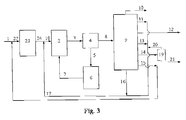
- FIG. 1 is the schematic principle flowsheet of the process of technical scheme 2
- the feedstock mixes through pipeline 1 with the cycle oil from pipeline 15, then enters hydrotreating unit 23 through pipeline 22, comes into contact with the hydrotreating catalyst and hydrogen, and reacts under the conditions of a hydrogen partial pressure between 3.0 MPa and 20.0 MPa, a reaction temperature between 300°C and 450°C:, a hydrogen/oil ratio between 300 and 2000 by volume, and a LHSV between 0.1 h 1 and 3.0 h -1 .
- the oil produced in the hydrotreating unit mixes through pipeline 24 with the recycle stream from pipeline 17, then enters catalytic cracking reactor 2, comes into contact with catalytic cracking and steam, and reacts under the conditions of a temperature between 500°C and 700°C, a pressure between 0.15-0.4 MPa (absolute pressure) a ratio of the catalytic cracking catalyst to catalytic cracking feedstock between 5 and 50 by weight, a ratio of steam to catalytic cracking feedstock between 0.05 and 1.0 by weight.
- the coked spent catalyst and reaction product vapor enters catalyst/oil separator 4 through pipeline 3, the separated spent catalyst enters regenerator 6 through pipeline 5.
- the catalyst regenerated by burning off coke possesses higher activity and selectivity, which returns to reactor 2 through pipeline 7, and the reaction product vapor enters product separator 9.
- the separated ethylene and propylene are withdrawn through pipeline 12, and the cracked naphtha from which C 5 -C 6 is removed enters solvent extraction unit 19.
- the obtained aromatics are withdrawn through pipeline 21, hydrogen and methane are withdrawn through pipeline 10, ethane and propane are withdrawn through pipeline 11, C 4 -C 6 are withdrawn through pipeline 13, the cycle oil is withdrawn through pipeline 15, and the slurry is withdrawn through pipeline 16.
- Ethane and propane, C 4 -C 6 , the extraction raffinate of naphtha, and slurry are all or partly return to catalytic cracking reactor 2 sequentially through pipelines 17 and 18, and the cycle oil return to hydrotreating unit 23 sequentially through pipelines 15 and 22.
- Figure 4 is the schematic principle flowsheet of the process and apparatus of technical scheme 3.
- feedstock mixes through pipeline 1 with diesel from pipeline 11 then enters hydrogenation unit A.
- H 2 , CH 4 , hydrotreated C 2 0 -C 4 0 , hydrotreated naphtha, and hydrotreated product obtained by hydrotreating are withdrawn from pipelines 2, 3, 4, and 5 respectively.
- the hydrotreated C 2 0 -C 4 0 and hydrotreated naphtha mixes respectively through pipelines 3 and 4 then enters steam cracking unit E sequentially through pipelines 23 and 24.
- the hydrotreated product as a feedstock tor catalytic cracking mixes with C 4 -C 5 from pipeline 26, then enters catalytic cracking unit B and reacts under the conditions of a temperature between 500°C and 700°C, a pressure between 0.15-0.4 MPa (absolute pressure), a ratio of the catalytic cracking catalyst to catalytic cracking feedstock between 5 and 50 hy weight, a ratio of steam to catalytic cracking feedstock between 0.05 and 1.0 by weight.
- the catalytic franking C 4 -C 5 mixes through pipeline 9 with steam cracking C 4 -C 5 from pipeline 18 then returns to catalytic cracking unit B sequentially through pipelines 26 and 27.
- the catalytic cracking naphtha mixes with stream cracking naphtha from pipeline 19 then enters selective hydrogenation unit C through pipeline 25.
- the diesel returns to hydrogenation unit A sequentially through pipelines 11 and 28.
- the cycle oil returns to catalytic cracking unit B through pipeline 12.
- the stream from selective hydrogenation unit C enters solvent extraction unit D.
- the BTX obtained in solvent extraction unit D are withdrawn from pipeline 14 as desired products, and the extraction raffinate enters steam cracking unit E sequentially through pipelines 13, 22, and 24.
- hydrotreated C 2 0 -C 4 0 , hydrotreated naphtha, catalytic cracking C 2 0 -C 3 0 , and extraction raffinate first mix respectively through pipelines 3, 4, 8, and 13, and then enter steam cracking unit E through pipeline 24.
- the refinery can produce light olefins such as propylene, ethylene, etc. to maximum, wherein the yield of propylene exceeds 20% by weight, preferably exceeds 25%, and more preferably exceeds 30%, and can also produce joint products, aromatics rich in toluene, xylene, etc. Therefore, a technical breakthrough of the refinery concept is realized, i.c., a conversion of the refinery from conventional fuel and fuel-lubricant production mode into chemical industry mode and a development and extension of the refinery from single oil refining to the production of downstream products with high added values. This conversion not only solves the problem of the shortage of the chemical feedstocks, but also increases the benefit of the refinery.
- the feedstock used in the examples is VGO, the properties are shown in Table 1, and the solvent used in the examples is sulfolane.
- the process for preparing the hydrotreating catalyst used in the examples is briefly described as follows: Ammonium metatungstate ((NH 4 W 4 O 13 ⁇ 18H 2 O, chemically pure) and nickel nitrate (Ni(NO 3 ) 2 -6H 2 O, chemically pure) were dissolved in water to prepare 200 ml of solution. 50 g of alumina support was added to the solution and impregnated at room temperature for 3 hours. During impregnation, the impregnating solution was treated with an ultrasonic instrument for 30 min, and then cooled, filtered and dried in a microwave oven for about 15 min. The composition of the catalyst was 30% by weight of WO 3 , 3.1% by weight of NiO, and balanced Alumina.
- the process for preparing the hydrotreating catalyst used in the examples is briefly described as follows: Ammonium metatungstate ((NH 4 W 4 O 13 ⁇ 18H 2 O, chemically pure) and nickel nitrate (Ni(NO 3 ) 2 ⁇ 6H 2 O, chemically pure) were dissolved in water to prepare 200 mL of solution. 100 g of alumina support was added to the solution and impregnated at room temperature for 4 hours. After separation, the wet catalyst was dried in a oven for 4 hours and calcined in a tube furnace with blowing air at 500°C for 4 hours. The composition of the catalyst was 25.3% by weight of WO 3 , 2.3% by weight of NiO, and balanced alumina.
- the experiment of the present example was carried out according to the flow in Figure 1.
- Feedstock A was directly used as the feedstock of catalytic cracking and the experiment was carried out in seven reaction zones consisting of risers and fluidized beds.
- the reaction temperatures of reaction zones I, II, III, IV, V, VI, and VII sequentially were 530°C, 520°C, 550°C, 540°C, 640°C, 620°C, and 580°C
- the WHSVs of reaction zones I, II, III, IV, V, VI, and VII sequentially were 360 h -1 , 720 h 1 , 20 h -1 , 180 h -1 , 5 h -1 , 200 h -1 , and 620 h -1 , wherein the reaction temperatures of reaction zones III and V were 20°C and 110°C higher than that of reaction zone 1 respectively, the the ratio of WHSVs of reaction zones III and V (fluidized bed) to that of reaction zone I (riser) were
- the experiment of the present example was carried out according to the flow in Figure 2.
- Feedstock B was directly used as the feedstock of catalytic cracking and the experiment was carried out in a medium-sized riser plus a fluidized bed reactor, wherein the reaction temperature of the fluidized bed was 30°C higher than that of the riser, the ratio of the WHSV of of the fluidized bed to that of the riser was 1:360, and the heat supplemented to the fluidized bed account for 22% of the reaction heat of the total reaction system.
- the products were separated, wherein only the slurry was cycled to the riser and C 4 -C 6 was cycled to the fluidized bed, but the other stream were not cycled.
- Table 2 The operating conditions of catalytic cracking and product distribution are shown in Table 2.
- the experiment of the present example was carried out according to the flow in Figure 3.
- Feedstock A was first subjected to hydrotreating, and the hydrotreated product (the content of hydrogen increased from 12.40% to 13.54% by weight and the content of aromatics decresed from 44.1% to 20.0% by weight) was used as the feedstock of catalytic cracking.
- the experiment was carried out in a medium-sized riser plus a fluidized bed reactor, wherein the reaction temperature of the fluidized bed was 40°C higher than that of the riser, the ratio of the WHSV of the fluidized bed to that of the riser was 1:30, and the heat supplemented Lo the fluidized bed account for 25% of the reaction heat of the total reaction system.
- the products were separated, wherein only the slurry was cycled to the riser, but the other stream were not cycled.
- Table 3 The operating conditions of hydrotreating and catalytic cracking and product distribution are shown in Table 3.
- the reactor for catalytic cracking is a riser plus a fluidized bed reactor in a pilot plant, wherein the reaction temperature of the fluidized bed was 40°C higher than that of the riser, the ratio of the WHSV of the fluidized bed to that of the riser was 1:30, and the heat supplemented to the fluidized bed account for 30% of the reaction heat of the total reaction system.
- the products were separated, wherein only the slurry was cycled to the riser, but the other stream were not cycled. All the hydrotreating, catalytic cracking, selective hydrogenation and solvent extraction experiments were carried out in corresponding middle-sized units.
- the feedstock used in the present example was the same as that in Example 3, i.e. feedstock A, and the operating conditions and product distribution arc shown in Table 3. It can be seen from Table 3 that the yields of propylene and ethylene are as high as 40.65% and 20.64% by weight respectively, and those of toluene and C 8 aromatics are 4.34% and 5.18% by weight respectively.
Landscapes
- Chemical & Material Sciences (AREA)
- Oil, Petroleum & Natural Gas (AREA)
- Organic Chemistry (AREA)
- Engineering & Computer Science (AREA)
- Chemical Kinetics & Catalysis (AREA)
- General Chemical & Material Sciences (AREA)
- Physics & Mathematics (AREA)
- Thermal Sciences (AREA)
- Production Of Liquid Hydrocarbon Mixture For Refining Petroleum (AREA)
- Organic Low-Molecular-Weight Compounds And Preparation Thereof (AREA)
- Catalysts (AREA)
Abstract
Description
- The present invention pertains to a process for the catalytic conversion of hydrocarbon oils in the absence of hydrogen, more particularly, it pertains to a process for converting heavy feedstocks into light olefins rich in propylene and ethylene and aromatics rich in toluene and xylene.
- Light olefins such as ethylene, propylene, etc. are important chemical feedstocks, wherein propylene is a synthetic monomer of the products such as polypropylene, acrylonitrile, etc. Along with the rapid increase of the demand for the derivatives such as polypropylene, etc. the demand for propylene is also rapidly increasing year by year, e.g., the demand of the world market for propylene already increased from 15.2 million tons of 20 years ago to 51.2 million tons of 2000 with an average annual increase rate of 6.3%. It is predicted that the demand for propylene will have attained 86 million tons by 2010 with an average annual increase rate of 5.6%.
- The process for producing propylene is mainly steam cracking and catalytic cracking (FCC), wherein steam cracking uses light oils such as naphtha, etc. as feedstocks to produce ethylene and propylene by thermal cracking with a propylene yield of only about 15% by weight, while FCC uses heavy oils such as vacuum gas oil (VGO) as feedstock. Presently, 66% propylene in the world comes from the byproducts of steam cracking for producing ethylene, 32% comes from the byproducts of FCC of refineries for producing naphtha and diesel, and a small amount. (about 2%) is obtained from the dehydrogenation of propane and metathesis of between ethylene and butene.
- If the petrochemical industry produces ethylene and propylene through the conventional steam cracking route, several restrictive factors would be faced such as shortage of light feedstocks, deficiency of the processing capacity, and high production cost.
- FCC is drawing increasing attention due to its advantages of wide adaptability, flexible operation, etc. In the United States of America, almost 50% of the demand of the market for propylene comes from FCC units. The development of the improved techniques of catalytic cracking for increasing the production of propylene is very rapid.
-
US Pat. No. 4,980,053 discloses a conversion process for producing light olefins from hydrocarbons, wherein the feedstocks are petroleum fractions, residuum, or crude oil with different boiling ranges and the converting reaction is carried out in a fluidized bed or moving bed reactor under the conditions of a temperature between 500°C and 650°C, a pressure between 1.5x10⁵ and 3x10⁵ Pa, a WHSV between 0.2 h1 and 2.0 h-1, and a catalyst to oil ratio between 2 and 12 by using a solid acid catalyst. The catalyst returns to the reactor for cycle use after being regenerated by burning off coke. By this process, the total yield of propylene and ethylene may attain about 40%, wherein the yield of propylene is up to 26.34%. -
WO 00/31215A1 -
US Pat. No. 6,123,830 discloses a combination process consisting of two stage catalytic cracking and two-stage hydrotreating, the objective of which is to produce as much olefins as possible and improve the quality of oil distillates and octane number of naphtha. The feedstock is converted into the first hydrotreated product in the first hydrotreating unit, and the first hydrotreated product enters the first catalytic cracking unit, wherein naphtha, diesel, and heavy oil are obtained by using a catalyst with a intermediate pore size zeolite as a main active component. The heavy oil enters the second hydrotreating unit for hydrogenation to obtain the second hydrotreated product, and the second hydrotreated product enters the second catalytic cracking unit for cracking, wherein the active component of the catalyst is mainly a intermediate pore size zeolite. The yield of propylene in this process is rather low. - Aromatics are also important, chemical feedstocks, in particular, light aromatics such as BTX (benzene, toluene, and xylene), which arc used to produce synthetic materials such as chemical fibers, plastics, etc. Presently, the major process for producing aromatics is catalytic reforming, wherein the feedstock should be fed to strict pretreatment because the active components of the reforming catalyst are noble metals. Besides, the process flow of the movement and regeneration of the reforming catalyst is complicated.
- The above prior arts produce propylene only as a byproduct with low yields not exceeding 30% at the same time when naphtha and diesel are produced. Some of them only can produce aromatics, but can not produce light olefins and aromatics simultaneously. In order to meet the increasing demand for the chemical feedstocks, propylene, ethylene, aromatics, etc. there is a necessity to develop a chemical industry type oil refining process for simultaneously producing large amounts of propylene, ethylene, and aromatics from heavy feedstocks.
- The objective of the present invention is Lo provide several processes for simultaneously producing propylene, ethylene, and aromatics from heavy feedstocks based on the prior art, the yield of propylene in these processes being higher than 20%.
- The process for producing light olefins and aromatics provided by the present invention comprises:
- A feedstock comes into contact with a catalytic cracking catalyst and reacts under the conditions of a reaction temperature between 400°C and 800°C, and a WHSV between 0.1 h1 and 750 h-1. The reaction is carried out in at least two reaction zones, and the reaction temperature of aL least one reaction zone among the reaction zones at the down stream side of the first reaction zone is higher than that of the first reaction zone and its WHSV is lower than that of the first reaction zone. The spent catalyst is separated from the reaction product vapor and the catalyst returns to the reactor after being regenerated. The reaction product vapor is separated to obtain the desired products, light olefins and aromatics.
- Another process for producing light olefins and aromatics provided by the present invention comprises:
- (1) A feedstock and optional cycle material come enter the hydrotreating unit, come into contact with a hydrotreating catalyst and hydrogen, and react under the conditions of a hydrogen partial pressure between 3.0 MPa and 20.0 MPa, a reaction temperature between 300°C and 450°C, a hydrogen/oil ratio between 300 and 2000 by volume, and a LHSV between 0.1 h-1 and 3.0 h1, and then the reaction effluent is separated to obtain hydrotreated product, with hydrogen being cycled for reuse;
- (2) The hydrotreated product comes into contact with a catalytic cracking catalyst and reacts under the conditions of a reaction temperature between 400°C and 800°C, and a WHSV between 0.1 h 1 and 750 h-1. The reaction is carried out in at least two reaction zones, and the reaction temperature of at least one reaction zone among the reaction zones at the down stream side of the first reaction zone is higher than that of the first reaction zone and its WHSV is lower than that of the first reaction zone. The spent catalyst is separated from the reaction product vapor and the catalyst returns to the reactor after being regenerated. The reaction product vapor is separated to obtain desired products, light olefins and aromatics.
- The third process for producing light olefins and aromatics provided by the present invention comprises:
- (1) A feedstock comes into contact with hydrogen and a hydrotreating catalyst and reacts under the conditions of a hydrogen partial pressure between 3.0 MPa and 20.0 Mpa, a reaction temperature between 300°C and 450°C, a hydrogen/oil ratio between 300 and 2000 by volume, and a LIINV between 0.1 h-1-3.0 h1, and then the reaction effluent is separated Lo obtain H2, CH4, hydrotreated C2 0-C4 0, hydrotreated naphtha, and hydrotreated product, with hydrogen being cycled for reuse;
- (2) The hydrotreated product of step (1) comes into contact with a catalytic cracking catalyst and reacts under the conditions of a reaction temperature between 400°C and 800°C and a WHSV between 0.1 h-1-750 h-1. The reaction is carried out in at least two reaction zones, and the reaction temperature of at least one reaction zone among the reaction zones at the down stream side of the first reaction zone is higher than that of the first reaction zone and its WHSV is lower than that of the first reaction zone. The spent catalyst is separated from the reaction product vapor and returns to all or a part of the reaction zones of step (2) after being stripped and regenerated. The reaction product vapor is separated to obtain H2, CH4, catalytic cracking C2 0-C3 0, catalytic cracking C2 0-C3 0, catalytic cracking C4-C5, catalytic cracking naphtha, LCO, and heavy cycle oil, wherein C2 --C3 - are a part of the desired products and catalytic cracking C4-C5 are cycled back to the catalytic cracking reactor;
- (3) The hydrotreated C2 0-C4 0 and hydrotreated naphtha of step (1) and catalytic cracking C2 0 C3 0 of step (2) come into contact with steam under a temperature between 700°C-1000°C, and the reaction product vapor is separated to obtain H2, CH4, steam cracking C2 0-C3 0, steam cracking C2 0-C4 0, steam cracking C4-C5, steam cracking naphtha, and fuel oil, wherein the steam cracking C2 --C3 - are a part of the desired products and the steam cracking C4-C5 are cycled back to the catalytic cracking reactor;
- (4) The catalytic cracking naphtha of step (2) and steam cracking naphtha of step (3) are fed to selective hydrogenation first, and then fed to solvent extraction to obtain aromatics and extraction raffinate, wherein the aromatics are a part of the desired products, and the extraction raffinate returns to step (3) as one of the feedstocks of steam cracking.
- The apparatus provided by the present invention comprise:
- (1) A hydrotreating unit, wherein H2, CH4, hydrotreated C2 0-C4 0, hydrotreated naphtha, and hydrotreated product arc obtained after a feedstock comes into contact with hydrogen and a hydrotreating catalyst;
- (2) A catalytic cracking unit, wherein the hydrotreated product comes into contact with a catalytic cracking catalyst. The reaction is carried out in at least two reaction zones, and the reaction temperature of at least one reaction zone among the reaction zones downstream of the first reaction zone is higher than that of the first reaction zone and its WHSV is lower than that of the first reaction zone. The spent catalyst is separated from the reaction product vapor, wherein the catalyst returns to all or a part of the reaction zones of step (2) after being stripped and regenerated, and the reaction product vapor is separated to obtain H2, CH4, catalytic cracking C2 - C3 -, catalytic cracking C2 0-C3 0, catalytic cracking C4-C5, catalytic cracking naphtha, LCO, and HCO. The C2 - C3 - are a part of the desired products, and the catalytic cracking C4-C5 are cycled back to the catalytic cracking reactor,
- (3) A steam cracking unit, wherein the hydrotreated C2 0-C4 0, hydrotreated naphtha, and catalytic cracking C2 0-C3 0 come into contact with steam under a temperature between 700°C and 1000°C and the reaction product vapor is separated to obtain H2, CH4, steam cracking C2 --C3 -, steam cracking C2 0-C3 0, steam cracking C4-C5, steam cracking naphtha, and fuel oil, wherein the steam cracking C2 --C3 - are a part of the desired products;
- (4) A selective hydrogenation unit, wherein the catalytic cracking naphtha and steam cranking naphtha are first fed to selective hydrogenation to obtain the selectively hydrotreated naphtha;
- (5) A solvent extraction unit, wherein the selectively hydrotreated naphtha is fed to solvent extraction to obtain aromatics and extraction raffinate. The aromatics are a part of the desired products, and the extraction raffinate returns to Lhe steam cracking unit as one of the feedstocks for steam cracking.
-
- Figure 1 is the schematic diagram of the catalytic cracking process of
technical scheme 1. - Figure 2 is the schematic diagram of a preferred catalytic cracking process of
technical scheme 1. - Figure 3 is the schematic principle flowsheet of the process of
technical scheme 2. - Figure 4 is the schematic principle flowsheet of the process and apparatus of technical scheme 3.
- The process of the present invention is particularly accomplished in the following ways :
- The process for producing light olefins and aromatics provided by the present invention comprises:
- A feedstock comes into contact with the a catalytic cracking catalyst and reacts under the conditions of a reaction temperature between 400°C and 800°C, and a WHSV between 0.1 h-1 and 750 h-1. The reaction is carried out in at least two reaction zones, and the reaction temperature of at least one reaction zone among the reaction zones downstream of the first reaction zone is higher than that of the first reaction zone and its WHSV is lower than that of the first reaction zone. The spent catalyst is separated from the reaction product vapor and the catalyst returns to the reactor after being regenerated. The reaction product vapor is separated to obtain the desired products, light olefins and aromatics.
- The present process will be described in detail as follows.
- 1) feedstock
Said feedstocks in each reaction zone in petroleum hydrocarbons and/or other mineral oils, wherein the petroleum hydrocarbon is one selected from the group consisting of vacuum gas oil (VGO), atmospheric gas oil (AGO), coked gas oil (CGO), deasphalted oil (DAO), vacuum residuum (VR), atmospheric residuum (AR), cycle oil, slurry, diesel, naphtha, hydrocarbons with 4-8 carbon atoms, alkanes with 2-3 carbon atoms or mixture thereof and the other mineral oil is liquid products from coal liquefaction, tar sand oil, or shale oil.
The preferable feedstock of the first reaction zone is one selected from the group consisting of vacuum gas oil, atmospheric gas oil, coked gas oil, deasphalted oil, vacuum residuum, atmospheric residuum, cycle oil, slurry, diesel, naphtha or mixture thereof.
The preferable, feed of reaction zones downstream of the first reaction zone is one selected from the group consisting of cycle oil, slurry, diesel, naphtha, hydrocarbons with 4-8 carbon atoms, alkanes with 2-3 carbon atoms or mixture thereof.
Wherein VGO, AGO, CGO, DAO, VR, AR, diesel, and naphtha are unhydrotreated or hydrotreated whole fraction or partial fraction.
Said naphtha is one selected from catalytic cracking naphtha, catalytic cracking naphtha, straight-run naphtha, coked naphtha, steam cracking naphtha, thermal cracking naphtha, and hydrotreated naphtha, or mixtures thereof, wherein catalytic cracking naphtha may be either from the catalytic cracking process of the present invention, or from conventional catalytic cracking, straight-run naphtha, coked naphtha, steam cracking naphtha, thermal cracking naphtha, and hydrotreated naphtha arc from outside of the present process.
Said diesel is one selected from catalytic cracking LCO, straight run diesel, coked diesel, thermal cracking diesel, and hydrotreated diesel obtained by the present process, or mixtures thereof, wherein catalytic cracking LCO may be either from the catalytic cracking process of the present invention, or from conventional catalytic cracking, straight run diesel, coked diesel, thermal cracking diesel, and hydrotreated diesel are from outside of the present process.
The hydrocarbons with 4-8 carbon atoms and alkanes with 2-3 carbon atoms can be either from the catalytic cracking process of the present invention, or from conventional catalytic cracking, coking, thermal cracking, hydrogenating, etc processes.
The feedstock of each reaction zone may be identical, or different. The feedstock of the first reaction zone prefers heavier hydrocarbons such as VCO, AGO, CGO, DAO, VR, AR, self-produced cycle oil, self-produced slurry, outside, cycle oil, outside slurry, diesel, and naphtha. The reaction zone with higher reaction temperature prefers lighter hydrocarbons such an hydrocarbons with 4-8 carbon atoms, alkanes with 2-3 carbon atoms, naphtha, and diesel. - 2) Catalytic cracking catalyst
The catalytic cracking catalyst comprises zeolite, inorganic oxide, and optional clay, which account for the following percent of the total weight of the catalyse respectively:zeolite 10%-50% by weight,inorganic oxide 5%-90% by weight, andclay 0%-70% by weight.
Wherein zeolite is an active component, which is selected from intermediate pore size zeolite and optional large pore zeolite. The intermediate pore size zeolite accounts for 25% 100%, preferably 50%-100% of the total weight of the zeolite and the large pore zeolite accounts for 0%-75%, preferably 0%-50% of the total weight of the zeolite. The intermediate pore size zeolite is selected from 2SM series zeolites and/or ZRP zeolites, or ZSM and ZRP zeolites modified with nonmetal elements such as phosphor and/or transition metal elements such as iron, cobalt, and nickel. SeeUS Pat. No. 5,232,675 for more detailed description of ZRP zeolites. The ZSM series zeolite is one selected from the group consisting of ZSM-5,ZSM 11, ZSM-12, ZSM-23, ZSM-35, ZSM-38, and ZSM-48, and other zeolites with similar structure, or mixtures thereof. Please refer toUS Pat. No. 3,702,886 for more detailed description of ZSM-5 zeolites. The large pore zeolite is one selected from the group consisting of rare-earth Y (REY), rare-earth HY(REHY), ultrastable Y and high silica Y obtained by different processes or mixtures thereof.
The inorganic oxide as a binder is selected from silica (SiO2) and/or alumina (Al2O3).
Clay as a matrix (i.e. supporter) is selected from kaolin and/or halloysite.
The catalytic crocking catalyst in each reactor may be identical or different. - 3) Catalytic cracking reactor
The cracking reactor comprises at least two, preferably 2-7, more preferably 2-3 reaction zones and each reaction zone is one selected from riser, fluidized bed, ascending transfer line, descending transfer line, and moving bed or some part thereof. The connection ways among various reaction zones are series, parallel, or series-parallel. The riser can be the conventional unidiameter, or various types of tapered risers. The structure and dimension of each reaction zone may be identical or different, wherein the velocity of the gas in the fluidized bed is between 0.1 m/s and 2.4 m/s (catalyst is neglected).
Said first reaction zone is a zone wherein a feedstock with a boiling range between 25°C and 1200°C comes into contact with the catalyst. The feedstock for the first reaction zone may also be a feedstock of the conventional catalytic cracking wherein a small amount of light hydrocarbons with boiling points lower than those of the feedstock of the conventional catalytic cracking such as C2-C6 may be incorporated. There may be other reaction zones upstream side of this reaction zone. The feedstock of the conventional catalytic cracking is one selected from the group consisting of vacuum gas oil, atmospheric gas oil, coked gas oil, deasphalted oil, vacuum residuum, atmospheric residuum, cycle oil, slurry, diesel, naphtha or mixture thereof.
The first reaction zone is preferably riser, ascending transfer line, descending transfer line, or fluidized bed, and more preferably riser or fluidized bed; the other reaction zone is preferably fluidized bed, riser, and moving bed, more preferably fluidized bed or riser. - 4) Operating conditions
The operating conditions arc as follows: reaction temperature 400°C-800°C, preferably 500°C-700°C, WHSV 0.1 h-1-750 h-1, preferably 1 h-1-500 h-1, reaction pressure 0.10 MFa-1.0 MPa (absolute pressure), ratio of catalytic cracking catalyst to feedstock 1-150 by weight. According to the common knowledge of the ordinary in the art, the reaction temperature of a tube reactor such as riser reactor means the outlet temperature, and the reaction temperature of a bed reactor such as fluidized bed reactor means the average temperature of the bed.
in order to realize the fluidized operation, a lifting medium may he injected from the bottom of the reaction zone and the lifting medium is selected from steam or dry gas with steam being preferred. The ratio of steam to the feedstock is 0.05-1.0 by weight.
The reaction temperature of at least one, preferably 1-6, and more preferably 1-2 reaction zones out of the reaction zones downstream of the first reaction zone is higher than that of the first reaction zone. The difference between the reaction temperature of the reaction zone with a higher reaction temperature and that of the first reaction zone is 10°C 200°C, preferably 20°C-100°C.
In order that the reaction temperature of at least one reaction zone out of the reaction zones downstream of the first reaction zone is higher than that of the first reaction zone, heat is supplemented to the above reaction zone by means of one or more of the ways selected form supplying hot regenerated catalyst, hot coke deposited catalyst, hot fresh catalyst, and hot feedstock to the reaction zone, or equipping heating coil pipes in the reaction zone. The total heat supplemented accounts for 10%-80%, preferably 20%-60% ot the reaction heat of the total reaction system.
The WHSV of at least one, preferably 1-6, and more preferably 1-2 reaction zones out of the reaction zones downstream of the first reaction zone is lower than that of the first reaction zone, and ratio of the WHSV of this reaction zone to that of the first reaction zone is 1:1.1-1:750, preferably 1:1.1-1:300.
The spent catalyst is separated from reaction product vapor by conventional disengaging, cyclone separation and the catalyst returns to the reactor after being regenerated by burning off coke, before which the catalyst is optionally fed to stripping. - 5) Separation of the product
Said light olefins are ethylene, propylene, and optional butene, i.e. light olefins are ethylene and propylene or ethylene, propylene, and butene. - The process for separating ethylene from the reaction product vapor is the same as that for separating ethylene,which is well known to the ordinary skilled in the art, and the process for separating propylene and optional butene from the reaction product vapor is the same as that for separating propylene and optional butene, which is well known to the ordinary skilled in the art. The process for separating aromatics from the cracking naphtha fraction of the reaction product, vapor is the same as that for separating aromatics, which is well known to the ordinary skilled in the art, i.e. extraction. Before separating aromatics from the catalytic cranking naphtha obtained by the present process, C5 C8 in this naphtha may be separated first as a recycle stream.
- The preferred technical scheme of this embodiment comprises the following steps:
- (1) the feedstock and steam enter first reaction zone, i.e. the riser, come into contact with a regenerated and/or fresh catalytic cracking catalyst and react under the conditions of a reaction temperature between 500°C and 700°C, a WHSV between 0.1 h-1 and 750 h 1, a reaction pressure between 0.1 Mpa and 1.0 Mpa (absolute pressure), a ratio of the catalytic cracking catalyst to the feedstock between 1 and 150 by weight, and a ratio of steam to the feedstock between 0.05 and 1.0 by weight;
- (2) the reaction effluent from the first reaction zone enters the second reaction zone, i.e. the fluidized bed, comes into contact with the regenerated catalytic cracking catalyst, steam, ethane, propane, C4-C8, and reacts under conditions of a reaction temperature between 500°C and 700°C, a WHSV between 0.1 h-1 and 750 h-1, a reaction pressure between 0.1 Mpa and 1.0 Mpa (absolute pressure), a ratio of the catalytic cracking catalyst to feedstock between 1 and 150 by weight, and a ratio of steam to feedstock between 0.05 and 1.0 by weight. The difference between the reaction temperature of the second reaction zone and that of the first reaction zone is 10°C-200°C, preferably 20°C-100°C, and the ratio of the WHSV of the second reaction zone to that of the first reaction zone is 1:1.1-1:750, preferably 1:1.1-1:300;
- (3) the spent catalyst in the second reaction zone is separated from the reaction product, vapor, wherein the spent catalyst enters the regenerator after stripping and returns to the first reaction zone and the second reaction zone after being regenerated by burning off coke, and the reaction product vapor is separated to obtain the desired products, light olefins and aromatics.
- The preferred technical scheme may further comprise step (4): remaining gases and liquids in the reaction gas-oil except, the desired products, H2 and CH4, are used as recycle streams, which comprise ethane, propane, and C4-C6 . The extraction raffinate obtained after the solvent extraction of the naphtha, returns to the second reaction zone, and the diesel, cycle oil, and slurry return to the first reaction zone.
- Another process for producing light olefins and aromatics present invention provided by the present invention comprises:
- (1) a feedstock and optional recycle stream enter Lhe hydrotreating unit first, comes into contact with a hydrotreating catalyst and hydrogen, and reacts under the conditions of a hydrogen partial pressure between 3.0 MPa and 20.0 MPa, a reaction temperature between 300°C and 450°C, a hydrogen/oil ratio between 300 and 2000 by volume, and a LHSV between 0.1 h-1 and 3.0 h-1. The reaction effluent is separated to obtain hydrotreated product and hydrogen is recycled for use.
- (2) the hydrotreated product comes into contact with a catalytic cracking catalyst and reacts under the conditions of a reaction temperature between 400°C and 800°C and a WHSV between 0.1 h-1-750 h1 in at least two reaction zones, wherein the reaction temperature of at least one reaction zone put of the reaction zones downstream of the first reaction zone is higher than that of the first reaction zone, and the WHSV of at least one reaction zone out of the reaction zones downstream ot the first reaction zone is lower than that of the first reaction zone. The spent catalyst is separated from the reaction product vapor. The spent catalyst is recycled for use after being regenerated and the reaction product vapor is separated to obtain the desired products, light olefins and aromatics.
- The present embodiment may further comprise step (3): the remaining gases and liquids in the reaction gas-oil except the desired products, H2, and CH4, are used as recycle streams, wherein the gas recycle streams are ethane, propane, and C4, and the liquid recycle streams are C5 C6, extraction raffinate of the naphtha, recycled oil and slurry. Ethane, propane, and C4-C6, and/or extraction raffinate of naphtha, diesel, cycle oil, and slurry. Ethane, propane, C4-C6, aforesaid extraction raffinate, diesel, or hydrotreated diesel, and slurry return to the reaction zone of step (2), and the cycle oil returns to the hydrotreating unit. The lower alkanes which do not participate reaction are withdrawn from the unit.
- The feedstock said is petroleum hydrocarbons and/or other mineral oils, wherein the petroleum hydrocarbon is one selected from the group consisting of VGO, AGO, CCO, DAO, VR, AR, diesel, and naphtha or mixtures thereof, and the other mineral oil is liquid products from coal liquefaction, tar sand oil, or shale oil.
- Wherein VGO, AGO, CGO, DAO, VR, AR, diesel, and naphtha are unhydrotreated or hydrotreated whole fraction or partial fraction.
- Said naphtha is one selected from catalytic cracking naphtha, straight-run naphtha, coked naphtha, steam cracking naphtha, thermal cracking naphtha, and hydrotreated naphtha, or mixtures thereof, wherein catalytic cracking naphtha may be either from the catalytic cracking process of the present invention, or from conventional catalytic cracking, straight-run naphtha, coked naphtha, steam cracking naphtha, thermal clacking naphtha, and hydrotreated naphtha are from outside of the present process.
- Said diesel is one selected from catalytic cracking LCO, catalytic cracking diesel, straight-run diesel, coked diesel, thermal cracking diesel, and hydrotreated diesel, or mixtures thereof, wherein catalytic cracking LCO may be either from the catalytic cracking process of the present invention, or from conventional catalytic cracking, straight-run diesel, coked diesel, thermal cracking diesel, and hydrotreated diesel are from outside of the present process.
- The feedstock and cycle oil in step (1) may enter the hydrotreating reactor together after mixing to reduce the investment on the equipment. The feedstock and cycle oil come into contact with a hydrotreating catalyst and hydrogen, and reacts under the conditions of a hydrogen partial pressure between 3.0 MPa and 20.0 MPa, a reaction temperature between 300°C and 450°C, a hydrogen/oil ratio between 300 and 2000 by volume, and a LHSV between 0.1 h-1 and 3.0 h-1. The reaction effluent is sequentially fed to high pressure separation, low pressure separation, and product fractionation to obtain hydrotreated product.
- It is preferred to hydrotreat heavy oil and cycle oil to obtain the optimum reaction effect, but the high pressure reparation, low pressure separation, and product fractionation systems may be shared. Besides, the two reaction systems may use a same pressure level in order to share the compressors of fresh hydrogen and recycle hydrogen. The conditions in the hydrogenation of the feedstock are: hydrogen partial pressure 3.0 MPa-20.0 MPa, reaction temperature 300°C 450°C, hydrogen/oil ratio 300-2000 by volume, and LHSV 0.1 h1-3.0 h-1 and the conditions of the hydrotreating of the cycle oil are: hydrogen partial pressure 3.0 MPa-20.0 MPa, reaction temperature 300°C-450°C, hydrogen/oil ratio 300-2000 by volume, and LHSV 0.2 h-1-2.0 h-1.
- The hydrotreating catalyst used in the hydrotreating unit is a catalyst of the non-noble metals of Croup VIB and/or Group VIII supported on alumina and/or amorphous silica-alumina. Said nom-noble metal of Group VIB is selected from Mo and/or w and that of Group VIII is selected from Co and/or Ni. High hydrosaturation and denitrogenation activities but a low cracking activity are required for this catalyst to reserve long straight chain paraffins in the feedstock as much as possible and produce more propylene in catalytic cracking process. The preferred catalyst comprises of 0-10% by weight an additive, 1-9% by weight of one or more of Group VIII metals, 12-39% by weight of one or more of Group VIB metals, and balanced alumina and/or amorphous silica-alumina as supports wherein the additive is selected from non-metal elements and metal elements such as fluorine, phosphor, titanium, etc.
- Compared with the feedstock, said hydrotreated product contains less sulfur, nitrogen, and aromatics, and a higher content of hydrogen, favorable for enhancing the yield of propylene when used as a feedstock for the catalytic cracking unit.
- The catalytic cracking catalyst, catalytic cracking reactor, and catalytic cracking operating conditions of the present technical scheme are the same as those of
technical scheme 2 respectively. - The third process for producing light olefins and aromatics present invention provided by the present invention comprises:
- (1) a feedstock comes into contact with hydrogen and a hydrotreating catalyst and reacts under the conditions of a hydrogen partial pressure between 3.0 MPa and 20.0 MPa, a reaction temperature between 300°C and 450°C, a hydrogen/oil ratio between 300-2000 by volume, and a LHSV between 0.1 h'-3.0 h-1, and then the reaction effluent is separated to obtain H2, CH4, hydrotreated C2 0-C4 0, hydrotreated naphtha, and hydrotreated product, the hydrotreated product, hydrogen being recycled for use;
- (2) the hydrotreated product of step (1) comes into contact with a catalytic cracking catalyst and reacts under the conditions of a reaction temperature between 400°C and 800°C and a WHSV between 0.1 h-1-750 h-1 in at least two reaction zones, wherein the reaction temperature of at least one reaction zone downstream of the first reaction zone is higher than that of the first reaction zone, and the WHSV of at least one reaction zone downstream of the first reaction zone i.s lower than that of the first reaction zone,; the spent catalyst is separated from the reaction product vapor, the spent catalyst returning to all or a part of the reaction zones of step (2) after being stripped and regenerated, and the reaction product vapor being separated to obtain H2, CH4, catalytic cracking C2 --C3 -, catalytic cracking C2 0-C3 0, catalytic cracking C4-C5, catalytic cracking naphtha, light cycle oil, heavy cycle oil, wherein the C2 --C3 - are a part of the desired products and the catalytic cracking C4-C5 are recycled to the catalytic pyrolyzed reactor;
- (3) the hydrotreated C2 0-C4 0 of step (1) and catalytic cracking C2 0-C3 0 of step (2) come into contact with steam under a temperature between 700°C-1000°C and the reaction product vapor is separated to obtain H2, CH4, steam cracking C2 0-C3 0, steam cracking C2 0-C3 0, steam cracking C4-C5, steam cracking naphtha, fuel oil, wherein the steam cracking C2 - C3 - are a part of the desired products and the steam cracking C4-C5 are recycled to the catalytic cracking reactor;
- (4) the catalytic cracking naphtha of step (2) and steam cracking naphtha of step (3) are fed to selective hydrogenation first, and then fed to solvent extraction to obtain aromatics and extraction raffinate, wherein the aromatics are a part of the desired products, the extraction raffinate returning to step (3) as one of the feedstocks of steam cracking.
- The feedstock, catalytic cracking catalyst, catalytic cracking reactor, and catalytic cracking operating conditions of the present technical scheme are the same as those of
technical scheme 2 respectively. - The solvent used in solvent extraction is one selected from the group consisting of sulfolane, N-methyl pyrrolidone, diethyl glycol ether, triethyl glycol ether, tetracthyl glycol, dimethyl sulfoxide, and N formyl morpholine and mixtures thereof. The temperature in solvent extraction is 80-120°C, and the ratio of the solvent to the extracted feedstock is 2-6 by volume. The extracted oil by solvent extraction is one of the desired products, aromatics and the extraction raffinate, i.e. non-aromatics, is one of the feedstocks for steam cracking.
- The feedstocks for steam cracking are the hydrotreated C2 0-C4 0 and hydrotreated naphtha of step (1) and catalytic cracking C2 0-C3 0 of step (2).
- The reaction conditions in steam cracking are: temperature 700°C-1000°C, residence time 0.05 s-0.6 s, and steam/oil ratio 0.1-1.0 by weight.
- The reaction product vapor is separated to obtain H2, CH4, steam cracking C2 --C3 -, steam cracking C2 0-C3 0, steam cracking C4-C5, steam cracking naphtha, fuel oil, wherein the steam cracking C2 --C3 - are a part of the desired products. The steam cracking C2 0-C3 0 are recycled to the steam cracking reactor and the steam cracked C4-C5 are recycled to the catalytic pyrolyzed reactor.
- The present technical scheme produces light olefins such as propylene, ethylene, etc, from heavy feedstocks as much as possible by integrating hydrotreating, catalytic cracking, steam cracking, solvent extraction, etc, wherein the yield of propylene exceeds 30%, and products aromatics such as toluene, xylene, etc. at the same time.
- The apparatus provided by the present invention comprises:
- (1) hydrotreating unit, wherein H2, CH4, hydrotreated C2 0-C4 0, hydrotreated naphtha, and hydrotreated product are obtained after the feedstock comes into contact with hydrogen and a hydrotreating catalyst.
- (2) Catalytic cracking unit, wherein the hydrotreated product comes into contact with a catalytic cracking catalyst and reacts under the conditions of a reaction temperature between 400°C and 800°C and a WHSV between 0.1 h1-750 h-1 in at least two reaction zones, wherein the temperature of at least one reaction zone downstream of the first reaction zone is higher than that of the first reaction zone, and the WHSV of at least one reaction zone downstream of the first reaction zone is lower than that of the first reaction zone; the spent catalyst is separated from the reaction product vapor, the spent catalyst returning to all or a part of the reaction zones of step (2) after being regenerated by stripping and the reaction product vapor being separated to obtain H2, CH4, catalytic cracking C2 --C3 -, catalytic cracking C2 0-C3 0, catalytic cracking C4-C5, catalytic cracking naphtha, light cycle oil, heavy cycle oil, wherein the C2 - C3 - are a part of the desired products and the C4-C5 are recycled to the catalytic cracking reactor;
- (3) Steam cracking unit wherein the hydrotreated C2 0-C4 0, hydrotreated naphtha, catalytic cracking C2 0-C3 0, and catalytic cracking C2 0-C3 0 come into contact with steam under a temperature between 700°C and 1000°C and the reaction product vapor is separated to obtain H2, CH4. steam cracking C2 --C3 -, steam crocking C2 0-C3 0, steam cracking C4-C5, steam cracking naphtha, fuel oil, wherein the steam cracking C2 --C3 - are a part of the desired products;
- (4) selective hydrogenation unit, wherein Lhe catalytic cracking naphtha and steam cracking naphtha are fed to selective hydrogenation to obtain the selectively hydrotreated naphtha ;
- (5) solvent extraction unit, wherein the selectively hydrotreated naphtha is fed to the solvent extraction to obtain aromatics and extraction raffinate, wherein the aromatics are a part of the desired products and the extraction raffinate returns to step (3) as one of the feedstocks of steam cracking.
- The process of the present invention will be further described bellow in combination with the drawings.
- Figure 1 in the schematic diagram of the catalytic cracking process of
technical scheme 1. - There are 7 reaction zones in this Figure, wherein the temperatures of both reaction zone III and reaction zone V are higher than that of reaction zone I and their WHSVs are lower than that of reaction zone I. Medium PS2 such as propane is injected from the pre lifting section of the catalyst P6 at the bottom of reaction zone I to carry out reaction. This pro-lifting section P6 can also be regarded as a reaction zone.
- The process flow is as follows:
- Regenerated catalyst Cl from the regenerator enters pre-lifting section of the catalyst P6 at the bottom of reaction zone I through catalyst pipeline P1, reacts with medium PS2 after being lifted by medium PSl. In reaction zone I, feedstock S1 comes into contact with the catalyst and stream from pre-lifting section P6 and reacts under a reaction temperature between 500°C and 650°C, a WHSV between 2 h-1 and 300 h-1, an catalyst/oil ratio between 3 and 20 by weight, and a reaction pressure between 0.12 MPa and 0.6 MPa (absolute pressure). The reaction product and catalyst then enter reaction zone II together.
- In reaction zone IT, the C4 hydrocarbons feedstock S2 from other catalytic cracking unit comes into contact with the catalyst and stream from
reaction zone 1 and reacts under a reaction temperature between 490°C and 640°C, a WHSV between 20 h-1 and 750 h-1, an catalyst/oil ratio between 3 and 20 by weight, and a reaction pressure between 0.12 MPa and 0.6 MPa (absolute pressure). The reaction product and catalyst then enter reaction zone III together. - Tn reaction zone III, the C4 hydrocarbons feedstock S3 from the present process comes into contact with the catalyst and stream from reaction zone II and the regenerated catalyst from pipeline P2 and reacts under a reaction temperature between 510°C and 660°C, a WHSV between 2 h-1 and 150 h1, an catalyst/oil ratio between 3 and 20 by weight, and a reaction pressure between 0.12 MPa and 0.6 MPa (absolute pressure). The reaction product and catalyst then enter reaction zone IV together.
- In reaction zone IV, the C5 hydrocarbons feedstock S4 from the present process comes into contact with the catalyst and stream from reaction zone III and reacts under a reaction temperature between 490°C and 640°C, a WHSV between 20 h-1 and 750 h-1, an catalyst/oil ratio between 3 and 20 by weight, and a reaction pressure between 0.12 MPa and 0.6 MPa (absolute pressure). The reaction product and catalyst then enter reaction zone V together.
- In reaction zone V, a part of feedstock and C5 hydrocarbons feedstock S5 from the present process come into contact and mix with the catalyst and stream from reaction zone IV, spent catalyst C5 from pipeline P5, regenerated catalyst C4 from pipeline P4, and the catalyst and reaction product after regenerated catalyst C3 from pipeline P3 contacts and reacts with propane PS3, and react under a reaction temperature between 510°C and 700°C, a WHSV between 1 h-1 and 100 h1, an catalyst/oil ratio between 3 and 50 by weight, and a reaction pressure between 0.12 MPa and 0.5 MPa (absolute pressure). The reaction product and catalyst then enter reaction zone VI together.
- In reaction zone VI, C6 feedstock S6 from the present process comes into contact and mixes with the catalyst and stream from reaction zone V and reacts under a reaction temperature between 510°C and 700°C, a WHSV between 20 h-1 and 700 h-1, an catalyst/oil ratio between 3 and 50 by weight, and a reaction pressure between 0.12 MPa and 0.6 MPa (absolute pressure). The reaction product and catalyst then enter reaction zone VII together.
- In reaction zone VII, water or steam S7 comes into contact and mixes with the catalyst and stream from reaction zone VI and reacts under a reaction temperature between 450°C and 700°C, a WHSV between 20 h-1 and 700 h-1, an catalyst/oil ratio between 3 and 50 by weight, and a reaction pressure between 0.12 MPa and 0.6 MPa (absolute pressure). The reaction products vapor and catalyst then enter the catalyst/products vapor separation system. The separated product vapor enters the product vapor separation system and the catalyst enters the regenerator for generation optionally after being stripped.
- Figure 2 is the schematic diagram of a preferred catalytic cracking process of
technical scheme 1. - In this process, the catalytic cracking
reactor 40 consists of the first reaction zone, i.e. riser A, the second reaction zone, i.e. fluidized bed B in series. The difference between the reaction temperature of the second reaction zone and that of the first reaction zone is 10°C-200°C, preferably 20°C-100°C, and the ratio of the WHSV of the second reaction zone to that of the first reaction zone is 1:1.1-1-750, preferably 1:1.1-1:300. - The process flow is as follow:
- The pre-lifting steam enters from the bottom of riser A through
pipeline 57 and the regenerated catalyst move upward along riser A with increasing velocity under the pre-lifting action of the steam. The feedstock is injected into riser A throughpipeline 5 together with atomizing steam frompipeline 39, comes into contact with the regenerated catalyst. After being lifted by the steam frompipeline 55, the regenerated catalyst frompipeline 54 enters thevertical transfer line 56 together with C2 0-C3 0 and C4-C8 frompipeline 26 and moves upward, and finally enters fluidized bed B to carry out reaction together with the product vapor and catalyst from riser A. Steam enters the bottom of fluidized bed B throughpipeline 41 to ensure the fluidization and reaction of fluidized bed B. The product vapor produced in fluidized bed B and the deactivated spent catalyst enter the cyclone indisengager 43 throughpipeline 42 to carry out the separation of the spent catalyst from the product vapor. The product vapor enterscollection chamber 44 and the catalyst fine powder returns to the disengager through the leg. The spent catalyst in the disengager flows towards strippingsection 47 and comes into contact with the steam frompipeline 48. The product vapor stripped from the spent catalyst enterschamber 44 through the cyclone. The spent catalyst after stripping entersregenerator 50 through slopedpipe 49. - Figure 3 is the schematic principle flowsheet of the process of
technical scheme 2 - The principle flow of the process after hydrotreating is briefly described as follows: the feedstock mixes through
pipeline 1 with the cycle oil frompipeline 15, then entershydrotreating unit 23 throughpipeline 22, comes into contact with the hydrotreating catalyst and hydrogen, and reacts under the conditions of a hydrogen partial pressure between 3.0 MPa and 20.0 MPa, a reaction temperature between 300°C and 450°C:, a hydrogen/oil ratio between 300 and 2000 by volume, and a LHSV between 0.1 h1 and 3.0 h-1. The oil produced in the hydrotreating unit mixes throughpipeline 24 with the recycle stream frompipeline 17, then enters catalytic crackingreactor 2, comes into contact with catalytic cracking and steam, and reacts under the conditions of a temperature between 500°C and 700°C, a pressure between 0.15-0.4 MPa (absolute pressure) a ratio of the catalytic cracking catalyst to catalytic cracking feedstock between 5 and 50 by weight, a ratio of steam to catalytic cracking feedstock between 0.05 and 1.0 by weight. The coked spent catalyst and reaction product vapor enters catalyst/oil separator 4 through pipeline 3, the separated spent catalyst entersregenerator 6 throughpipeline 5. The catalyst regenerated by burning off coke possesses higher activity and selectivity, which returns toreactor 2 throughpipeline 7, and the reaction product vapor entersproduct separator 9. The separated ethylene and propylene are withdrawn throughpipeline 12, and the cracked naphtha from which C5-C6 is removed enterssolvent extraction unit 19. The obtained aromatics are withdrawn throughpipeline 21, hydrogen and methane are withdrawn throughpipeline 10, ethane and propane are withdrawn throughpipeline 11, C4-C6 are withdrawn throughpipeline 13, the cycle oil is withdrawn throughpipeline 15, and the slurry is withdrawn throughpipeline 16. Ethane and propane, C4-C6, the extraction raffinate of naphtha, and slurry are all or partly return to catalytic crackingreactor 2 sequentially throughpipelines hydrotreating unit 23 sequentially throughpipelines - Figure 4 is the schematic principle flowsheet of the process and apparatus of technical scheme 3.
- The principle flow of the present process is as follows: feedstock mixes through
pipeline 1 with diesel frompipeline 11 then enters hydrogenation unit A. H2, CH4, hydrotreated C2 0-C4 0, hydrotreated naphtha, and hydrotreated product obtained by hydrotreating are withdrawn frompipelines pipelines 3 and 4 then enters steam cracking unit E sequentially throughpipelines pipeline 26, then enters catalytic cracking unit B and reacts under the conditions of a temperature between 500°C and 700°C, a pressure between 0.15-0.4 MPa (absolute pressure), a ratio of the catalytic cracking catalyst to catalytic cracking feedstock between 5 and 50 hy weight, a ratio of steam to catalytic cracking feedstock between 0.05 and 1.0 by weight. H2, CH4, catalytic cracking C2 --C3, catalytic cracking C2 0-C4 0, catalytic cracking C4-C5, catalytic cracking naphtha, diesel, cycle oil obtained in catalytic cracking unit B are withdrawn frompipelines pipelines pipeline 9 with steam cracking C4-C5 frompipeline 18 then returns to catalytic cracking unit B sequentially throughpipelines pipeline 19 then enters selective hydrogenation unit C throughpipeline 25. The diesel returns to hydrogenation unit A sequentially throughpipelines pipeline 12. The stream from selective hydrogenation unit C enters solvent extraction unit D. The BTX obtained in solvent extraction unit D are withdrawn frompipeline 14 as desired products, and the extraction raffinate enters steam cracking unit E sequentially throughpipelines - The hydrotreated C2 0-C4 0, hydrotreated naphtha, catalytic cracking C2 0-C3 0, and extraction raffinate first mix respectively through
pipelines pipeline 24. H2, CH4, steam cracked C2 --C3 -, steam cracked C2 0-C3 0, steam cracked C4-C5, steam cracked naphtha, and fuel oil are withdrawn respectively throughpipelines pipeline 16 as one of the desired products, the steam cracked C2 0-C3 0 returns to steam cracking unit E throughpipeline 17, the steam cracked C4-C5 enters catalytic cracking unit R sequentially throughpipelines pipeline 19. - By using the several processes provided hy the present invention, the refinery can produce light olefins such as propylene, ethylene, etc. to maximum, wherein the yield of propylene exceeds 20% by weight, preferably exceeds 25%, and more preferably exceeds 30%, and can also produce joint products, aromatics rich in toluene, xylene, etc. Therefore, a technical breakthrough of the refinery concept is realized, i.c., a conversion of the refinery from conventional fuel and fuel-lubricant production mode into chemical industry mode and a development and extension of the refinery from single oil refining to the production of downstream products with high added values. This conversion not only solves the problem of the shortage of the chemical feedstocks, but also increases the benefit of the refinery.
- The following examples will further describe the present invention but not limit it.
- The feedstock used in the examples is VGO, the properties are shown in Table 1, and the solvent used in the examples is sulfolane.
- The process for preparing the catalytic cracking catalyst used in the examples is briefly described as follows:
- 1) 20 g of NH4Cl was dissolved in 1000 g of water, whereto 100 g (dry basis) ot crystallized product ZRP-1 zeolite (produced in the catalyst Plant of Qilu Petrochemicals Co., SiO2/Al2O3=30, content of race earths RE2O3=4.0% by weight) was added, and a filter cake was obtained after exchanging at 90°C for 0.5 hour and filtration. The filter cake was impregnated with a solution of 4.0 g of H3PO4 (with a concentration of 85%) and 4.5 g of Fe(NO3)3 in 90 g of water and then dried. The resultant solid was calcined at 550°C for 2 hours to obtain a intermediate pore size zeolite containing phosphor and iron and having the structure of MFI, the composition of which determined by element analysis was 0.1Na2O·5. 1Al2O4·2.4P3O5·1.5Fe2O3·8.8RE2O3·88.1SiO2.
- 2) 75.4 kg of halloysite (Product of Suzhou Porcelain Clay Co., solid content 71.6% by weight) was slurried with 250 kg of cation-removed water and 54.8 kg of pseudo-boehmite (industrial product of Shandong Alumina Plant, solid content 63% by weight) was added. PH is adjusted at 2-4 with hydrochloric acid, the slurry was uniformly stirred, and laid aside for aging at 60-70°C for 1 hour. The temperature was lowered down to below 60°C while maintaining the pII at 2 4, and then 4.5 kg of alumina sol (industrial product of Shandong Alumina Plant, Al2O3 content 21.7% by weight) was added. A mixed slurry was obtained after stirring for 40 min.
- 3) The intermediate pore size zeolite containing phosphor and iron and having the structure of MFI prepared in step 1) (
dry basis 45 kg) and DASY zeolite (industrial product of the Catalyst Plant of Qilu Petrochemicals Co., unit cell size 2.445-2.448 nm, RE2O3 content 2.0%, dry basis 7.5 kg) were added to the mixed slurry obtained in step 2) and uniformly stirred. The resulted slurry was shaped by spray drying, and the product was washed with a solution of ammonium dihydrogen phosphate (phosphor content 1% by weight) to remove free Na+. After drying, a sample of the catalytic cracking catalyst was obtained. The composition of the catalyst was 30% by weight of MFI structure intermediate pore size zeolite containing phosphor and iron, 5% by weight of DASY zeolite, 23% by weight of pseudo-boehmite, 6% by weight of alumina sol, and balanced kaolin. - The process for preparing the hydrotreating catalyst used in the examples is briefly described as follows: Ammonium metatungstate ((NH4W4O13·18H2O, chemically pure) and nickel nitrate (Ni(NO3)2-6H2O, chemically pure) were dissolved in water to prepare 200 ml of solution. 50 g of alumina support was added to the solution and impregnated at room temperature for 3 hours. During impregnation, the impregnating solution was treated with an ultrasonic instrument for 30 min, and then cooled, filtered and dried in a microwave oven for about 15 min. The composition of the catalyst was 30% by weight of WO3, 3.1% by weight of NiO, and balanced Alumina.
- The process for preparing the hydrotreating catalyst used in the examples is briefly described as follows: Ammonium metatungstate ((NH4W4O13·18H2O, chemically pure) and nickel nitrate (Ni(NO3)2·6H2O, chemically pure) were dissolved in water to prepare 200 mL of solution. 100 g of alumina support was added to the solution and impregnated at room temperature for 4 hours. After separation, the wet catalyst was dried in a oven for 4 hours and calcined in a tube furnace with blowing air at 500°C for 4 hours. The composition of the catalyst was 25.3% by weight of WO3, 2.3% by weight of NiO, and balanced alumina.
- The experiment of the present example was carried out according to the flow in Figure 1. Feedstock A was directly used as the feedstock of catalytic cracking and the experiment was carried out in seven reaction zones consisting of risers and fluidized beds. The reaction temperatures of reaction zones I, II, III, IV, V, VI, and VII sequentially were 530°C, 520°C, 550°C, 540°C, 640°C, 620°C, and 580°C, and the WHSVs of reaction zones I, II, III, IV, V, VI, and VII sequentially were 360 h-1, 720 h1, 20 h-1, 180 h-1, 5 h-1, 200 h-1, and 620 h-1, wherein the reaction temperatures of reaction zones III and V were 20°C and 110°C higher than that of
reaction zone 1 respectively, the the ratio of WHSVs of reaction zones III and V (fluidized bed) to that of reaction zone I (riser) were 1:18 and 1:72 respectively, and the heats supplemented to reaction zones III and V account for 11% and 60% of the reaction heat of the total reaction system respectively. Finally, the products were separated, wherein C3-C5 was cycled to the fluidized beds. The operating conditions of reaction zones I, III, and V, and product distribution are shown in Table 2. - It can be seen from Table 2 that the yields of propylene and ethylene attain as high as 35.21% and 14.56% by weight respectively, and those of toluene and xylene are 3.95% and 4.26% by weight respectively.
- The experiment of the present example was carried out according to the flow in Figure 2. Feedstock B was directly used as the feedstock of catalytic cracking and the experiment was carried out in a medium-sized riser plus a fluidized bed reactor, wherein the reaction temperature of the fluidized bed was 30°C higher than that of the riser, the ratio of the WHSV of of the fluidized bed to that of the riser was 1:360, and the heat supplemented to the fluidized bed account for 22% of the reaction heat of the total reaction system. Finally, the products were separated, wherein only the slurry was cycled to the riser and C4-C6 was cycled to the fluidized bed, but the other stream were not cycled. The operating conditions of catalytic cracking and product distribution are shown in Table 2.
- It can be seen from Table 2 that the yields of propylene and ethylene arc as high as 30.46% and 18.31% by weight respectively, and those of toluene and xylene are 2.45% and 7.38% by weight respectively.
- The experiment of the present example was carried out according to the flow in Figure 3. Feedstock A was first subjected to hydrotreating, and the hydrotreated product (the content of hydrogen increased from 12.40% to 13.54% by weight and the content of aromatics decresed from 44.1% to 20.0% by weight) was used as the feedstock of catalytic cracking. The experiment was carried out in a medium-sized riser plus a fluidized bed reactor, wherein the reaction temperature of the fluidized bed was 40°C higher than that of the riser, the ratio of the WHSV of the fluidized bed to that of the riser was 1:30, and the heat supplemented Lo the fluidized bed account for 25% of the reaction heat of the total reaction system. Finally, the products were separated, wherein only the slurry was cycled to the riser, but the other stream were not cycled. The operating conditions of hydrotreating and catalytic cracking and product distribution are shown in Table 3.
- It can he seen from Table 3 that the yields of propylene and ethylene are as high as 32.97% and 12.63% by weight respectively, and those of toluene and xylene are 1.93% and 4.05% by weight respectively.
- The experiment of the present, example was carried out according to the flow in Figure 4. The reactor for catalytic cracking is a riser plus a fluidized bed reactor in a pilot plant, wherein the reaction temperature of the fluidized bed was 40°C higher than that of the riser, the ratio of the WHSV of the fluidized bed to that of the riser was 1:30, and the heat supplemented to the fluidized bed account for 30% of the reaction heat of the total reaction system. Finally, the products were separated, wherein only the slurry was cycled to the riser, but the other stream were not cycled. All the hydrotreating, catalytic cracking, selective hydrogenation and solvent extraction experiments were carried out in corresponding middle-sized units.
- The feedstock used in the present example was the same as that in Example 3, i.e. feedstock A, and the operating conditions and product distribution arc shown in Table 3. It can be seen from Table 3 that the yields of propylene and ethylene are as high as 40.65% and 20.64% by weight respectively, and those of toluene and C8 aromatics are 4.34% and 5.18% by weight respectively.
Table 1 Examples 1, 3,4 Example 2 No. of feedstock A B Property of feedstock Density (20°c)g/cm3 0.8886 0.9134 Sulfur content, ppm 4700 5800 Nitrogen content, ppm 1600 2900 Aromatics m% 26.3 32.6 C, m% 86.46 86.23 H, m% 12.86 12.69 Boiling range (ASTM D-1160, °c IBP 312 327 10% 361 363 30 % 412 409 50% 452 450 70 % 478 482 90 % 506 504 95% 532 526 FBP 546 542 Table 2 Example1 Example 2 Example 3 No. of feedstock A B A Hydrotreating unit Operation condition Reaction temperature °C - - 370 Hydrogen partial pressure MPa - - 14.0 LHSV, h-1 - - 0.6 Hydrogen/oil ratio v/v - - 800 Product distribution, m% Gas - - 2.55 Naphtha - - 1.80 Hydrotreated product - - 96.90 Catalytic cracking unit Operation condition Riser reaction zone I Reaction temperature °c 530 650 580 Catalyst/oil ratio, m/m 8 20 12 WHSV, h-1 360 180 120 Steam injected to feed m% 20 10 15 Fluidized bed reaction zone III/V Reaction Temperature °c 550/640 680 620 Catalyst/oil ratio, m/m 10/30 45 25 WHSV, h-1 20 /5 0.5 4 Water injected to feed m% 20/ 25 60 30 Temperature difference between riser and the bed, °c 20/ 110 30 40 WHSV ratio (the fluidized bed / riser) 1:18 /1:72 1:360 1:30 Product distribution, m% H2 & CH4 5.46 6.47 4.36 Ethylene 14.56 18.31 12.63 Propylene 35.21 30.46 32.97 Ethane & propane 4.23 5.17 4.73 C4 4.54 0 18.68 C5-C6 2.53 0 1.86 Toluene 3.95 2.45 1.93 Xylene 4.26 7.38 4.05 Other single-ring aromatics 2.78 9.76 3.86 Extraction raffinate of pyrolyzed naphtha 5.59 1.84 1.09 Cycle oil 7.04 8.68 3.50 Slurry 0 0 2.28 Coke 9.85 9.48 8.06 Table 3 Example 4 Hydrotreating unit Reaction temperature, °c 370 Hydrogen partial pressure, MPa 14.0 LHSV, h-1 0.6 H2/oil ratio, v/v 800 Catalytic cracking unit Riser Reaction temperature °c 580 Catalyst/oil ratio, m/m 12 WHSV, h-1 120 Water injected (ratio to feed), m% 15 Fluidized bed Reaction temperature, °c 620 Catalyst/oil ratio, m/m 25 WHSV, h-1 4 Water injected (ratio to feed), m% 30 Temperature difference between the fluidized bed/riser °c 40 WHSV ratio (the fluidized bed/riser) 1:30 Selective hydrogenation unit Reaction temperature °c 200 Hydrogen partial pressure, MPa 4.0 LHSV, h-1 2.5 Hydrogen/oil ratio, v/v 350 Solvent extraction unit Temperature, °c 90 Solvent ratio, v/v 3.5 Yield of product, m% Methane & hydrogen 8.60 Ethylene 20.64 Propylene 40.65 Benzene 1.28 Toluene 4.34 C8 aromatics 5.18 C9 + heavy aromatics 6.03 Fuel oil 2.5 Coke 10.78
Claims (30)
- A process for producing light olefins and aromatics, which comprises reacting the feedstock by contacting with a catalytic cracking catalyst under conditions of a reaction temperature between 400°C and 800°C and a weight hourly space velocity (WHSV) between 0.1 h-1 and 750 h-1, separating the spent catalyst from the reaction product vapor, regenerating the spent catalyst and returning the regenerated catalyst to the reactor, characterized in that the reaction was carried out in at least two reaction zones, wherein the reaction temperature of at least one reaction zone among the reaction zones downstream of the first reaction zone is higher than that of the first reaction zone and its WHSV is lower than that of the first reaction zone.
- The process according to claim 1, characterized in that said first reaction zone is a reaction zone wherein a feedstock with a boiling range of 25°C-1200°C comes into contact with the catalyst.
- The process according to claim 1, characterized in that the reaction is carried out in 2-7 reaction zones, wherein the reaction temperatures of 1-6 reaction zones among the reaction zones downstream of the first reaction zone is higher than that of the first reaction zone and their WHSVs are lower than that of the first reaction zone.
- The process according to claim 1, characterized in that the reaction in carried out in 2-3 reaction zones, wherein the reaction temperatures of 1-2 reaction zones among the reaction zones downstream of the first reaction zone is higher than that of the first reaction zone and their WHSVs are Lower than that of the first reaction zone.
- The process according to claim 1, characterized in that the difference between the reaction temperature of the reaction zone with a higher reaction temperature and that of the first reaction zone is 10°C-200°C, and the ratio of the WHSV of this reaction zone to that of the first reaction zone is 1:1.1-1:/50.
- The process according to claim 1, characterized in that the difference between the reaction temperature of the reaction zone with a higher temperature and that of the first reaction zone is 20°C-100°C, and the ratio of the WHSV of this reaction zone to that of the first reaction zone is 1:1.1-1:300.
- The process according to claim 1, characterized in that the sources of the heat for the reaction zone with a higher reaction temperature is one selected from the group consisting of the hot regenerated catalyst, hot coke deposited catalyst, hot fresh catalyst, and hot feedstock, and one or more heating coil tubes are equipped in this reaction zone, or mixtures thereof.
- The process according to claim 1, characterized in that the total heat supplemented to the reaction zone with a higher reaction temperature accounts for 10%-80% of the reaction heat of the whole reaction system.
- The process according to claim 1, characterized in that the total heat supplemented to the reaction zone with a higher reaction temperature accounts for 20%-60% of the reaction heat of the whole reaction system.
- The process according to claim 1, characterized in that the conditions in each said reaction zone are: reaction temperature 500°C-700°C, WHSV 1 h1-500 h-1, reaction pressure 0.10 MPa-1.0 MPa, ratio of the catalytic cracking catalyst to the feedstock 1-150 by weight.
- The process according to claim 1, characterized in that each said reaction zone is one selected from a riser, fluidized bed, ascending transfer line, descending transfer line, and moving bed, and the connecting ways among various reaction zones are series, parallel, or mixed.
- The process according to claim 1, characterized in that said feedstock is petroleum hydrocarbons and/or other mineral oils, wherein the petroleum hydrocarbon is one selected from the group consisting of vacuum gas oil, atmospheric gas oil, coked gas oil, deasphalted oil, vacuum residuum, atmospheric residuum, cycle oil, slurry, diesel, naphtha, hydrocarbons with 4 8 carbon atoms, alkanes with 2-3 carbon atoms or mixture thereof, and the other mineral oil is liquid products from coal liquefaction, tar sand oil, or shale oil.
- The process according to claim 1, characterized in that the feedstock of the first reaction zone is one selected from the group consisting of vacuum gas oil, atmospheric gas oil, coked gas oil, deasphalted oil, vacuum residuum, atmospheric residuum, cycle oil, slurry, diesel, naphtha or mixture thereof.
- The process according to claim 1, characterized in that the feedstock of the reaction zones downstream of Lhe first reaction zone is one selected from the group consisting of cycle oil, slurry, diesel, naphtha, hydrocarbons with 4-8 carbon atoms, alkanes with 2-3 carbon atoms or mixture thereof.
- The process according to claims 12 or 13, characterized in that said vacuum gas oil, atmospheric gas oil, coked gas oil, deasphalted oil, vacuum residuum, atmospheric residuum, diesel, and naphtha are their whole fraction or partial fraction.
- The process according to any of claims 12, 13 or 14, characterized in that said naphtha is one selected from the group consisting of catalytic cracking naphtha, straight-run naphtha, coked naphtha, steam cracking naphtha, thermal cracking naphtha, and hydrotreated naphtha, or mixtures thereof.
- The process according to any of claims 12, 13 or 14, characterized in that said diesel is one selected from the group consisting of catalytic cracking light cycle oil(LCO), straight-run diesel, coked diesel, thermal cracking diesel, and hydrotreated diesel, or mixtures thereof.
- The process according to claim 1, characterized in that said catalytic cracking catalyst comprises zeolites, inorganic oxides, and optional clays, and the contents of various components in Lhe catalyst are: zeolite 10%-50% hy weight, inorganic oxide 5% 90% by weight, and clay 0%-70% by weight.
- The process according to claim 18, characterized in that said zeolite is an intermediate pore size zeolite and optional large pore zeolite, wherein the intermediate pore size zeolite accounts for 25%-100% of the total weight of the zeolite and the large pore zeolite accounts for 0% 75% by weight of the total amount of the zeolite; the intermediate pore size zeolite is selected from ZSM series zeolites and/or ZRP zeolites, and the ZSM series zeolite is one selected from group consisting ot ZSM 5, ZSM-11, ZSM-12, ZSM-23, ZSM-3b, ZSM-38, and ZSM-48, or mixtures thereof; the large pore zeolite is one selected from the group consisting of rare earth Y, rare earth HY, ultrastable Y, and high silica Y, or mixtures thereof.
- The process according to claim 18, characterized in that said inorganic oxide is selected from SiO2 and/or Al2O3, and the clay is selected from kaolin clay and/or halloysite.
- The process according to claim 1, characterized in that said low olefins is ethylene, propylene, and optional butene.
- A process for producing light olefins and aromatics, characterised in that it comprises the following steps:(1) A feedstock and optional recycle stream enter the hydrotreating unit, come into contact with a hydrotreating catalyst and hydrogen, and react under the conditions of a hydrogen partial pressure between 3.0 MPa and 20.0 MPa, a reaction temperature between 300°C and 450°C, a hydrogen/oil ratio between 300 and 2000 by volume, and a liquid hourly space velocity (LHSV) between 0.1 h-1-3.0 h-1, the reaction effluent is separated to obtain the hydrotreated product, and hydrogen is cycled for reuse;(2) The hydrotreated product is fed to catalytic cracking according to the process said in claim 1.
- A process for producing light olefins and aromatics, characterised in that it comprises:(1) A feedstock comes into contact with hydrogen and a hydrotreating catalyst and reacts under the conditions of a hydrogen partial pressure between 3.0 MPa and 20.0 MPa, a reaction temperature between 300°C and 450°C, a hydrogen/oil volume ratio between 300-2000, and a liquid hourly space velocity (LHSV) between 0.1 h-1-3.0 h-1, and then the reaction effluent is separated to obtain H2, CH4, hydrotreated C2 0-C4 0, hydrotreated naphtha, and hydrotreated product, with hydrogen being cycled for reuse;(2) The hydrotreated product of step (1) is fed to catalytic cracking according to the process said in claim 1, wherein spent catalyst is separated from the reaction product vapor, the catalyst returns to all or a part of the reaction zones of step (2) after being stripped and regenerated, and the reaction product-vapor is separated to obtain H2, CH4, catalytic cracking C2 --C3 -, catalytic cracking C2 0-C3 0, catalytic cracking C4-C5, catalytic cracking naphtha, LCO, and heavy cycle oil (HCO), wherein the C2 0-C3 0 are a part of the desired products and the C4-C5 are cycled back to the catalytic cracking reactor;(3) The hydrotreated C2 0-C4 0 and hydrogenated naphtha of step (1) and catalytic cracking C2 0-C3 0 ot step (2) come into contact with steam under a temperature between 700°C-1000°C and the reaction product vapor is separated to obtain H2, CH4, steam cracking C2 --C3 -, steam cracking C2 0-C3 0, steam cracking C4-C5, steam cracking naphtha, and fuel oil, wherein the steam cracking C2 +-C3 - are a part of the desired products and the steam cracking C4-C5 are cycled to the catalytic cracking reactor;(4) The catalytic cracking naphtha of step (2) and steam cracking naphtha of step (3) arc fed to selective hydrogenation first, and then ted to solvent extraction to obtain aromatics and extraction raffinate, wherein the aromatics arc a part of the desired products, and the extraction raffinate returns to step (3) as one of the feedstocks of steam cracking.
- The process according to claims 22 or 23, characterized in that the hydrotreating catalyst said in step (1) is a catalyst of a non-noble metal of VIB Group and/or Group VIII supported on alumina and/or amorphous silica-alumina.
- The process according to claim 24, characterized in that said non-noble metal of VIB Group is selected from Mo and/or W and that of Group VIII is selected from Co and/or Ni.
- The process according to claim 23, characterized in that the conditions for steam cracking in step (3) are a temperature between 700°C and 1000°C, a residence time between 0.05 seconds and 0.6 seconds, and a steam to oil ratio between 0.1-1.0 by weight.
- The process according to claim 23, characterized in that the conditions for selective hydrogenation of step (4) are a hydrogen partial pressure between 1.2 MPa and 8.0 MPa, a reaction temperature between 150°C and 300°C, a hydrogen to oil ratio between 150 and 600 by volume, and a LHSV between 1 h1 and 20 h-1.
- The process according to claim 23, characterized in that the solvent said in step (4) is one selected from the group consisting of sulfolane, N-methyl pyrrolidone, diethyl glycol ether, triethyl glycol ether, tetraethyl alcohol, dimethyl sulfoxide, and N-fnrmyl morpholine and mixtures thereof.
- The process according to claim 23, characterized in that the temperature for the solvent extraction in step (4) is 80°C-120°C and the ratio of the solvent to the feed for extraction is 2-6 by volume.
- An apparatus for producing light olefins and aromatics, characterised in that it comprises:(1) A hydrotreating unit, wherein. H2, CH4, hydrotreated C2 0-C4 0, hydrotreated naphtha, and hydrotreated product are obtained after the feedstock comes into contact with hydrogen and a hydrotreating catalyst;(2) A catalytic cracking unit, wherein the hydrotreated product fed to catalytic cracking according to the process said in claim 1, wherein spent catalyst is separated from the reaction product vapor, wherein the catalyst returns to all or a part of the reaction zones of the step (2) after being stripped and regenerated and the reaction product vapor is separated Lo obtain H2/CH4, catalytic cracking C2 --C3 -, catalytic cracking C2 0-C3 0, catalytic cracking C4-C2, catalytic cracking naphtha, LCO, and HCO, wherein the C2 --C3 - are a part of the desired products and the C4-C5 are cycled back to the catalytic pyrolyzing reactor;(3) steam cracking unit, wherein the hydrotreated C2 0 - C4 0, hydrotreated naphtha, and catalytic cracking C2 0-C3 0 come into contact with steam under a temperature between 700°C and 1000°C and the reaction product vapor is separated to obtain H2/CH4, steam cracking C2 --C3 -, steam cracking C2 0-C3 0, steam cracking C4-C5, steam cracking naphtha, and fuel oil, wherein the steam cracking C2 --C3 - are a part of the desired products;(4) Selective hydrogenation unit, wherein the catalytic cracking naphtha and steam cracking naphtha are first fed to selective hydrogenation to obtain the selectively hydrogenated naphtha;(5) Solvent extraction unit, wherein the selectively hydrogenated naphtha is fed to the solvent extraction to obtain aromatics and extraction raffinate. The aromatics are a part of the desired products and the extraction raffinate returns to step (3) as one of the feedstocks for steam cracking.
Priority Applications (1)
| Application Number | Priority Date | Filing Date | Title |
|---|---|---|---|
| EP17151967.1A EP3225678B1 (en) | 2004-03-08 | 2005-03-08 | Am fcc process with two reaction zones |
Applications Claiming Priority (3)
| Application Number | Priority Date | Filing Date | Title |
|---|---|---|---|
| CNB2004100061891A CN100487080C (en) | 2004-03-08 | 2004-03-08 | Chemical oil-refining method for preparing low carbon olefin and arene |
| CNB2004100689345A CN1333052C (en) | 2004-07-14 | 2004-07-14 | Method and device for preparing low carbon olefine and arene |
| PCT/CN2005/000281 WO2005085391A1 (en) | 2004-03-08 | 2005-03-08 | A process of production of lower olefins and aromaticas |
Related Child Applications (1)
| Application Number | Title | Priority Date | Filing Date |
|---|---|---|---|
| EP17151967.1A Division EP3225678B1 (en) | 2004-03-08 | 2005-03-08 | Am fcc process with two reaction zones |
Publications (2)
| Publication Number | Publication Date |
|---|---|
| EP1734098A1 true EP1734098A1 (en) | 2006-12-20 |
| EP1734098A4 EP1734098A4 (en) | 2012-04-04 |
Family
ID=34921082
Family Applications (2)
| Application Number | Title | Priority Date | Filing Date |
|---|---|---|---|
| EP05714812A Ceased EP1734098A4 (en) | 2004-03-08 | 2005-03-08 | PROCESS FOR PRODUCTION OF LOWER OLEFINS AND AROMATIC ELEMENTS |
| EP17151967.1A Expired - Lifetime EP3225678B1 (en) | 2004-03-08 | 2005-03-08 | Am fcc process with two reaction zones |
Family Applications After (1)
| Application Number | Title | Priority Date | Filing Date |
|---|---|---|---|
| EP17151967.1A Expired - Lifetime EP3225678B1 (en) | 2004-03-08 | 2005-03-08 | Am fcc process with two reaction zones |
Country Status (8)
| Country | Link |
|---|---|
| US (2) | US8778170B2 (en) |
| EP (2) | EP1734098A4 (en) |
| JP (1) | JP4808209B2 (en) |
| KR (1) | KR101147469B1 (en) |
| BR (1) | BRPI0508591B1 (en) |
| ES (1) | ES2913654T3 (en) |
| SA (1) | SA05260089B1 (en) |
| WO (1) | WO2005085391A1 (en) |
Cited By (10)
| Publication number | Priority date | Publication date | Assignee | Title |
|---|---|---|---|---|
| US20110207979A1 (en) * | 2008-10-07 | 2011-08-25 | Sk Innovation Co., Ltd. | Method for producing high value aromatics and olefin from light cycle oil produced by a fluidized catalytic cracking process |
| RU2497933C2 (en) * | 2008-03-13 | 2013-11-10 | Чайна Петролеум & Кемикал Корпорейшн | Method for conversion of low-grade raw feedstock to high-quality oil fuel |
| EP2773602A4 (en) * | 2011-11-01 | 2015-07-22 | Sk Innovation Co Ltd | PROCESS FOR THE PRODUCTION OF AROMATIC HYDROCARBONS AND OLEFINS FROM HYDROCARBON OILS CONTAINING LARGE AMOUNTS OF POLYCYCLIC AROMATIC COMPOUNDS |
| EP2184335A4 (en) * | 2007-08-09 | 2016-01-27 | China Petroleum & Chemical | CATALYTIC CONVERSION METHOD |
| US9260667B2 (en) | 2007-12-20 | 2016-02-16 | China Petroleum & Chemical Corporation | Combined process of hydrotreating and catalytic cracking of hydrocarbon oils |
| US9388096B2 (en) | 2011-05-24 | 2016-07-12 | Jx Nippon Oil & Energy Corporation | Producing method of monocyclic aromatic hydrocarbons and monocyclic aromatic hydrocarbon production plant |
| WO2017109639A1 (en) | 2015-12-21 | 2017-06-29 | Sabic Global Technologies B.V. | Methods and systems for producing olefins and aromatics from coker naphtha |
| EP3305748A4 (en) * | 2015-06-02 | 2019-01-23 | Dalian Institute Of Chemical Physics, Chinese Academy of Sciences | PROCESS FOR CONVERTING NAPHTHA |
| CN115957700A (en) * | 2021-10-12 | 2023-04-14 | 中国石油天然气股份有限公司 | Device and method for preparing propylene/ethylene through catalytic conversion of petroleum hydrocarbon |
| US11896963B1 (en) * | 2022-09-26 | 2024-02-13 | Saudi Arabian Oil Company | Mesoporous ZSM-5 for steam enhanced catalytic cracking of crude oil |
Families Citing this family (94)
| Publication number | Priority date | Publication date | Assignee | Title |
|---|---|---|---|---|
| KR100632571B1 (en) * | 2005-10-07 | 2006-10-09 | 에스케이 주식회사 | Process for quenching light olefin hydrocarbon compound from hydrocarbon raw material mixture through catalytic cracking process |
| CN1986505B (en) * | 2005-12-23 | 2010-04-14 | 中国石油化工股份有限公司 | A catalytic conversion method for increasing production of low-carbon olefins |
| CN101191073B (en) * | 2006-11-30 | 2012-03-07 | 中国石油化工股份有限公司 | Method for producing high octane rating low olefin gasoline |
| KR100914887B1 (en) * | 2007-11-09 | 2009-08-31 | 한국에너지기술연구원 | Tapered Regeneration Reactor Of CO2 Capture System using Dry-sorbent |
| JP5340620B2 (en) * | 2008-03-27 | 2013-11-13 | Jx日鉱日石エネルギー株式会社 | Catalyst composition and method for producing aromatic hydrocarbon |
| JP5736633B2 (en) * | 2008-04-18 | 2015-06-17 | 株式会社明電舎 | Catalyst and production method thereof |
| US9827558B2 (en) | 2010-01-20 | 2017-11-28 | Jx Nippon Oil & Energy Corporation | Catalyst for production of hydrocarbons and method of producing hydrocarbons |
| KR101790368B1 (en) * | 2010-01-20 | 2017-10-25 | 제이엑스티지 에네루기 가부시키가이샤 | Catalyst for use in production of monocyclic aromatic hydrocarbon, and process for production of monocyclic aromatic hydrocarbon |
| US8618011B2 (en) | 2010-04-09 | 2013-12-31 | Kellogg Brown & Root Llc | Systems and methods for regenerating a spent catalyst |
| US8808535B2 (en) | 2010-06-10 | 2014-08-19 | Kellogg Brown & Root Llc | Vacuum distilled DAO processing in FCC with recycle |
| KR101735108B1 (en) * | 2010-09-16 | 2017-05-15 | 에스케이이노베이션 주식회사 | The method for producing valuable aromatics and olefins from hydrocarbonaceous oils derived from coal or wood |
| US9387449B2 (en) | 2010-11-11 | 2016-07-12 | Baozhen Shi | Catalytic cracking method and apparatus |
| US8975462B2 (en) | 2010-11-25 | 2015-03-10 | Sk Innovation Co., Ltd. | Method for producing high-added-value aromatic products and olefinic products from an aromatic-compound-containing oil fraction |
| WO2012091119A1 (en) * | 2010-12-28 | 2012-07-05 | Jx日鉱日石エネルギー株式会社 | Catalyst for producing monocylic aromatic hydrocarbon and method for producing monocyclic aromatic hydrocarbon |
| CN102304382A (en) * | 2011-08-18 | 2012-01-04 | 苏州工业园区大华石油有限公司 | Process for coproducing aromatic oil, asphalt and fuel oil |
| US9238600B2 (en) * | 2011-12-14 | 2016-01-19 | Uop Llc | Dual riser catalytic cracker for increased light olefin yield |
| US20130261365A1 (en) * | 2012-04-02 | 2013-10-03 | Saudi Arabian Oil Company | Process for the Production of Xylenes and Light Olefins from Heavy Aromatics |
| US20130338418A1 (en) * | 2012-06-14 | 2013-12-19 | Saudi Arabian Oil Company | Direct catalytic cracking of crude oil by a temperature gradient process |
| FR2995610B1 (en) * | 2012-09-14 | 2014-10-10 | Seppic Sa | NOVEL METHOD FOR DRILLING GROUND CAVITIES, NOVEL ALKYLPOLYGLYCOSIDE-BASED COMPOSITIONS AND THEIR USE AS A LUBRICANT AGENT IN THE PREPARATION OF AQUEOUS DRILLING FLUIDS |
| KR102202084B1 (en) | 2013-02-21 | 2021-01-13 | 에네오스 가부시키가이샤 | Method for producing single-ring aromatic hydrocarbons |
| EP3017027B1 (en) * | 2013-07-02 | 2018-06-06 | Saudi Basic Industries Corporation | Process for the production of light olefins and aromatics from a hydrocarbon feedstock |
| CN105452423B (en) * | 2013-07-02 | 2019-04-23 | 沙特基础工业公司 | Process for producing aromatics and light olefins from hydrocarbon feedstocks |
| US20150073183A1 (en) * | 2013-09-10 | 2015-03-12 | Uop Llc | Production of olefins from a methane conversion process |
| US9079816B2 (en) | 2013-11-19 | 2015-07-14 | Uop Llc | Process for producing alkylated aromatic compounds |
| US9181500B2 (en) | 2014-03-25 | 2015-11-10 | Uop Llc | Process and apparatus for recycling cracked hydrocarbons |
| US10385279B2 (en) | 2014-03-25 | 2019-08-20 | Uop Llc | Process and apparatus for recycling cracked hydrocarbons |
| JP6258756B2 (en) * | 2014-04-04 | 2018-01-10 | 出光興産株式会社 | Method for producing fuel oil base material |
| US9228138B2 (en) | 2014-04-09 | 2016-01-05 | Uop Llc | Process and apparatus for fluid catalytic cracking and hydrocracking hydrocarbons |
| US9394496B2 (en) | 2014-04-09 | 2016-07-19 | Uop Llc | Process for fluid catalytic cracking and hydrocracking hydrocarbons |
| US9243195B2 (en) | 2014-04-09 | 2016-01-26 | Uop Llc | Process and apparatus for fluid catalytic cracking and hydrocracking hydrocarbons |
| US9399742B2 (en) | 2014-04-09 | 2016-07-26 | Uop Llc | Process for fluid catalytic cracking and hydrocracking hydrocarbons |
| US9422487B2 (en) | 2014-04-09 | 2016-08-23 | Uop Llc | Process for fluid catalytic cracking and hydrocracking hydrocarbons |
| JP6283561B2 (en) * | 2014-04-23 | 2018-02-21 | 出光興産株式会社 | Method for producing fuel oil base material |
| EP3169753B1 (en) | 2014-07-17 | 2020-06-10 | SABIC Global Technologies B.V. | Upgrading hydrogen deficient streams using hydrogen donor streams in a hydropyrolysis process |
| US9777229B2 (en) | 2015-03-10 | 2017-10-03 | Uop Llc | Process and apparatus for hydroprocessing and cracking hydrocarbons |
| US9783749B2 (en) | 2015-03-10 | 2017-10-10 | Uop Llc | Process and apparatus for cracking hydrocarbons with recycled catalyst to produce additional distillate |
| US9890338B2 (en) * | 2015-03-10 | 2018-02-13 | Uop Llc | Process and apparatus for hydroprocessing and cracking hydrocarbons |
| US9809766B2 (en) * | 2015-03-10 | 2017-11-07 | Uop Llc | Process and apparatus for producing and recycling cracked hydrocarbons |
| US9732290B2 (en) | 2015-03-10 | 2017-08-15 | Uop Llc | Process and apparatus for cracking hydrocarbons with recycled catalyst to produce additional distillate |
| US9567537B2 (en) | 2015-03-10 | 2017-02-14 | Uop Llc | Process and apparatus for producing and recycling cracked hydrocarbons |
| US10781382B2 (en) | 2015-11-12 | 2020-09-22 | Sabic Global Technologies B.V. | Methods for producing aromatics and olefins |
| JP6693826B2 (en) | 2016-07-20 | 2020-05-13 | Jxtgエネルギー株式会社 | Method for producing lower olefin and monocyclic aromatic hydrocarbon having 6 to 8 carbon atoms, production apparatus for lower olefin and monocyclic aromatic hydrocarbon having 6 to 8 carbon atoms |
| EP3555236A1 (en) * | 2016-12-19 | 2019-10-23 | SABIC Global Technologies B.V. | Process integration for cracking light paraffinic hydrocarbons |
| US10711208B2 (en) | 2017-06-20 | 2020-07-14 | Saudi Arabian Oil Company | Process scheme for the production of optimal quality distillate for olefin production |
| JP2020531603A (en) * | 2017-08-28 | 2020-11-05 | サウジ アラビアン オイル カンパニーSaudi Arabian Oil Company | Chemical loop process for catalytic hydrocarbon decomposition |
| WO2019162395A1 (en) | 2018-02-22 | 2019-08-29 | Total Research & Technology Feluy | Improved naphtha steam cracking process |
| EP3788026A1 (en) * | 2018-04-30 | 2021-03-10 | SABIC Global Technologies B.V. | Process of producing light olefins from isomerized straight run naphtha |
| EP3830222A1 (en) * | 2018-07-27 | 2021-06-09 | SABIC Global Technologies B.V. | Catalytic cracking of light naphtha over dual riser fcc reactor |
| CN112703176B (en) | 2018-09-20 | 2023-12-19 | 沙特基础工业全球技术公司 | Method for producing light olefins (ethylene + propylene) and BTX using a mixed C4 paraffin feed |
| US10954457B2 (en) | 2019-02-13 | 2021-03-23 | Saudi Arabian Oil Company | Methods including direct hydroprocessing and high-severity fluidized catalytic cracking for processing crude oil |
| EP4004152A1 (en) | 2019-07-31 | 2022-06-01 | SABIC Global Technologies, B.V. | Naphtha catalytic cracking process |
| EP3990572B1 (en) | 2019-07-31 | 2025-11-19 | SABIC Global Technologies, B.V. | Naphtha catalytic cracking process |
| US20220259505A1 (en) * | 2019-08-05 | 2022-08-18 | Sabic Global Technologies B.V. | A method for catalytic cracking of hydrocarbons to produce olefins and aromatics without steam as diluent |
| CN114207090A (en) * | 2019-08-05 | 2022-03-18 | 沙特基础工业全球技术公司 | Dense phase riser for maximizing low carbon olefin yield in naphtha catalytic cracking |
| FR3102772B1 (en) * | 2019-11-06 | 2021-12-03 | Ifp Energies Now | OLEFINS PRODUCTION PROCESS INCLUDING DESASPHALTING, HYDROCRACKING AND VAPOCRAQUAGE |
| FR3104604B1 (en) | 2019-12-16 | 2022-04-22 | Ifp Energies Now | Device and process for the production of light olefins and aromatics by catalytic cracking. |
| FR3104605B1 (en) | 2019-12-16 | 2022-04-22 | Ifp Energies Now | Device and process for the production of light olefins by catalytic cracking and steam cracking. |
| EP4127105A1 (en) | 2020-03-30 | 2023-02-08 | Hindustan Petroleum Corporation Limited | Simultaneous production of high value de-aromatized kerosene and btx from refinery hydrocarbons |
| CN111718231B (en) * | 2020-07-09 | 2023-07-04 | 青岛京润石化设计研究院有限公司 | Method and device for preparing ethylene and propylene by catalytic conversion of crude oil |
| CN114057532B (en) * | 2020-07-31 | 2023-12-12 | 中国石油化工股份有限公司 | A method for producing light aromatics and propylene |
| CN114057533B (en) * | 2020-07-31 | 2023-12-12 | 中国石油化工股份有限公司 | A method for producing light aromatics and light olefins |
| US11473022B2 (en) | 2021-01-07 | 2022-10-18 | Saudi Arabian Oil Company | Distillate hydrocracking process with an n-paraffins separation step to produce a high octane number isomerate stream and a steam pyrolysis feedstock |
| US11807818B2 (en) * | 2021-01-07 | 2023-11-07 | Saudi Arabian Oil Company | Integrated FCC and aromatic recovery complex to boost BTX and light olefin production |
| TWI882134B (en) * | 2021-01-11 | 2025-05-01 | 大陸商中國石油化工科技開發有限公司 | A fluidized catalytic conversion method for maximizing the production of propylene |
| US11820949B2 (en) | 2021-01-15 | 2023-11-21 | Saudi Arabian Oil Company | Apparatus and process for the enhanced production of aromatic compounds |
| CN115873630B (en) * | 2021-09-29 | 2025-02-11 | 中国石油化工股份有限公司 | A method for processing high aromatics feedstock oil |
| CN116083122B (en) * | 2021-11-05 | 2024-07-12 | 中国石油化工股份有限公司 | A method for producing ethylene and propylene from heavy hydrocarbons |
| CN116083121B (en) * | 2021-11-05 | 2024-07-09 | 中国石油化工股份有限公司 | A method for producing low-carbon olefins and light aromatics from heavy hydrocarbons |
| CN116144397B (en) * | 2021-11-19 | 2024-10-29 | 中国石油天然气集团有限公司 | A method and system for producing low-carbon olefins and light aromatics from heavy oil |
| CN116286077B (en) * | 2021-12-13 | 2025-06-03 | 中国海洋石油集团有限公司 | Method for directly preparing chemicals from crude oil |
| CN114686252B (en) * | 2021-12-26 | 2024-02-09 | 中海油天津化工研究设计院有限公司 | Method for preparing chemicals from crude oil |
| CN116554927B (en) * | 2022-01-28 | 2024-10-11 | 中国石油化工股份有限公司 | Method and system for producing low-carbon olefin and aromatic hydrocarbon by heavy oil |
| CN116554923B (en) * | 2022-01-28 | 2024-10-11 | 中国石油化工股份有限公司 | Method and system for producing low-carbon olefin by heavy oil |
| US11827855B1 (en) | 2022-07-06 | 2023-11-28 | Saudi Arabian Oil Company | Process and nano-ZSM-5 based catalyst formulation for cracking crude oil to produce light olefins and aromatics |
| US12012554B2 (en) | 2022-07-06 | 2024-06-18 | Saudi Arabian Oil Company | Process and catalyst formulation for cracking crude oil to produce light olefins and aromatics |
| US11866651B1 (en) | 2022-11-09 | 2024-01-09 | Saudi Arabian Oil Company | Process and catalyst formulation for cracking crude oil |
| US11866660B1 (en) | 2022-11-09 | 2024-01-09 | Saudi Arabian Oil Company | Process and catalyst formulation for cracking crude oil |
| EP4624445A4 (en) * | 2022-11-24 | 2026-01-14 | Dalian Inst Chem & Physics Cas | Fluidized bed device and method for producing aromatic hydrocarbons from naphtha |
| WO2024108511A1 (en) * | 2022-11-24 | 2024-05-30 | 中国神华煤制油化工有限公司 | Device and method for preparing aromatic hydrocarbons by coupling naphtha and methanol |
| JP2025521073A (en) * | 2022-11-24 | 2025-07-08 | 中国神▲華▼煤制油化工有限公司 | DEVICE AND METHOD FOR PRODUCING AROMATIC HYDROCARBONS FROM NAPHTHA |
| CN115738917B (en) * | 2022-11-25 | 2024-10-29 | 清华大学 | A system and synthesis process for catalytic conversion of diesel to olefins |
| US11814593B1 (en) | 2022-12-12 | 2023-11-14 | Saudi Arabian Oil Company | Processes for hydroprocessing and cracking crude oil |
| US11814594B1 (en) | 2022-12-12 | 2023-11-14 | Saudi Arabian Oil Company | Processes for hydroprocessing and cracking crude oil |
| US12163096B2 (en) | 2023-02-02 | 2024-12-10 | Saudi Arabian Oil Company | Multi-zone catalytic cracking of crude oils |
| US11866663B1 (en) | 2023-02-02 | 2024-01-09 | Saudi Arabian Oil Company | Multi-zone catalytic cracking of crude oils |
| US11866662B1 (en) | 2023-02-02 | 2024-01-09 | Saudi Arabian Oil Company | Multi-zone catalytic cracking of crude oils |
| US11905475B1 (en) | 2023-02-02 | 2024-02-20 | Saudi Arabian Oil Company | Multi-zone catalytic cracking of crude oils |
| US11866659B1 (en) | 2023-02-02 | 2024-01-09 | Saudi Arabian Oil Company | Multi-zone catalytic cracking of crude oils |
| US11898110B1 (en) | 2023-02-02 | 2024-02-13 | Saudi Arabian Oil Company | Multi-zone catalytic cracking of crude oils |
| US11866661B1 (en) | 2023-02-02 | 2024-01-09 | Saudi Arabian Oil Company | Multi-zone catalytic cracking of crude oils |
| US12209224B2 (en) | 2023-02-02 | 2025-01-28 | Saudi Arabian Oil Company | Multi-zone catalytic cracking of crude oils |
| US11939539B1 (en) | 2023-06-09 | 2024-03-26 | Saudi Arabian Oil Company | Multi-zone catalytic cracking of crude oils |
| CN119899544B (en) * | 2023-10-26 | 2026-07-14 | 中国石油化工股份有限公司 | LCO conductive carbon black method and system |
| CN119912974B (en) * | 2023-10-30 | 2025-11-14 | 中国石油化工股份有限公司 | A crude oil processing method and system for maximizing the production of chemical products and marine fuel. |
Family Cites Families (31)
| Publication number | Priority date | Publication date | Assignee | Title |
|---|---|---|---|---|
| US3702886A (en) | 1969-10-10 | 1972-11-14 | Mobil Oil Corp | Crystalline zeolite zsm-5 and method of preparing the same |
| US3862254A (en) * | 1970-10-16 | 1975-01-21 | Air Prod & Chem | Production of aromatic hydrocarbons |
| US3775290A (en) * | 1971-06-28 | 1973-11-27 | Marathon Oil Co | Integrated hydrotreating and catalytic cracking system for refining sour crude |
| US3894934A (en) * | 1972-12-19 | 1975-07-15 | Mobil Oil Corp | Conversion of hydrocarbons with mixture of small and large pore crystalline zeolite catalyst compositions to accomplish cracking cyclization, and alkylation reactions |
| US3928172A (en) * | 1973-07-02 | 1975-12-23 | Mobil Oil Corp | Catalytic cracking of FCC gasoline and virgin naphtha |
| US4090948A (en) * | 1977-01-17 | 1978-05-23 | Schwarzenbek Eugene F | Catalytic cracking process |
| US4218306A (en) | 1979-01-15 | 1980-08-19 | Mobil Oil Corporation | Method for catalytic cracking heavy oils |
| US4225418A (en) * | 1979-06-07 | 1980-09-30 | Uop Inc. | Hydroprocessing of hydrocarbons |
| US4436613A (en) * | 1982-12-03 | 1984-03-13 | Texaco Inc. | Two stage catalytic cracking process |
| CN1004878B (en) | 1987-08-08 | 1989-07-26 | 中国石油化工总公司 | Hydrocarbon catalytic conversion method for preparing low-carbon olefin |
| US4840928A (en) | 1988-01-19 | 1989-06-20 | Mobil Oil Corporation | Conversion of alkanes to alkylenes in an external catalyst cooler for the regenerator of a FCC unit |
| EP0381870B1 (en) * | 1989-02-08 | 1993-05-12 | Stone & Webster Engineering Corporation | Process for the production of olefins |
| DD287948B5 (en) | 1989-09-18 | 1996-09-05 | Buna Sow Leuna Olefinverb Gmbh | Process for the preparation of lower olefins and aromatics by pyrolysis of high boiling hydrocarbon fractions |
| US5154818A (en) * | 1990-05-24 | 1992-10-13 | Mobil Oil Corporation | Multiple zone catalytic cracking of hydrocarbons |
| CN1026225C (en) | 1991-02-28 | 1994-10-19 | 中国石油化工总公司石油化工科学研究院 | Preparation method for rare earth Y molecular sieve |
| JPH0711259A (en) * | 1993-06-22 | 1995-01-13 | Idemitsu Kosan Co Ltd | How to process heavy oil |
| CN1034586C (en) * | 1993-11-05 | 1997-04-16 | 中国石油化工总公司 | Catalytic conversion method of low-carbon olefines high-output |
| US5582714A (en) | 1995-03-20 | 1996-12-10 | Uop | Process for the removal of sulfur from petroleum fractions |
| US5685972A (en) | 1995-07-14 | 1997-11-11 | Timken; Hye Kyung C. | Production of benzene, toluene, and xylene (BTX) from FCC naphtha |
| US5773676A (en) * | 1996-08-06 | 1998-06-30 | Phillips Petroleum Company | Process for producing olefins and aromatics from non-aromatics |
| JPH1046160A (en) * | 1996-08-07 | 1998-02-17 | Nippon Oil Co Ltd | Fluid catalytic cracking of heavy oil |
| US5906728A (en) * | 1996-08-23 | 1999-05-25 | Exxon Chemical Patents Inc. | Process for increased olefin yields from heavy feedstocks |
| EP0988354A1 (en) * | 1997-06-10 | 2000-03-29 | Exxon Chemical Patents Inc. | Hydrocarbon cracking with positive reactor temperature gradient |
| CN1056595C (en) | 1997-10-20 | 2000-09-20 | 中国石油化工总公司 | Process for direct-conversion preparation olefines from multiple fed hydrocarbon |
| CN1058046C (en) * | 1997-11-11 | 2000-11-01 | 中国石油化工总公司 | Catalyst cracking method for producing in high-yield olefin and lift-leg reaction system thereof |
| US6113776A (en) * | 1998-06-08 | 2000-09-05 | Uop Llc | FCC process with high temperature cracking zone |
| CA2319263A1 (en) | 1998-11-24 | 2000-06-02 | Arthur W. Chester | Catalytic cracking for olefin production |
| US6123830A (en) * | 1998-12-30 | 2000-09-26 | Exxon Research And Engineering Co. | Integrated staged catalytic cracking and staged hydroprocessing process |
| EP1190019A1 (en) * | 2000-02-16 | 2002-03-27 | Indian Oil Corporation Limited | A multi stage selective catalytic cracking process and a system for producing high yield of middle distillate products from heavy hydrocarbon feedstocks |
| CN100572507C (en) * | 2003-03-18 | 2009-12-23 | 上海鲁齐信息科技有限公司 | The production premium is also increased production light product and the catalytic conversion process of propylene and device |
| US7128827B2 (en) * | 2004-01-14 | 2006-10-31 | Kellogg Brown & Root Llc | Integrated catalytic cracking and steam pyrolysis process for olefins |
-
2005
- 2005-03-08 KR KR1020067018080A patent/KR101147469B1/en not_active Expired - Lifetime
- 2005-03-08 ES ES17151967T patent/ES2913654T3/en not_active Expired - Lifetime
- 2005-03-08 EP EP05714812A patent/EP1734098A4/en not_active Ceased
- 2005-03-08 EP EP17151967.1A patent/EP3225678B1/en not_active Expired - Lifetime
- 2005-03-08 US US10/592,166 patent/US8778170B2/en active Active
- 2005-03-08 JP JP2007502171A patent/JP4808209B2/en not_active Expired - Lifetime
- 2005-03-08 BR BRPI0508591-8A patent/BRPI0508591B1/en active IP Right Grant
- 2005-03-08 WO PCT/CN2005/000281 patent/WO2005085391A1/en not_active Ceased
- 2005-04-12 SA SA05260089A patent/SA05260089B1/en unknown
-
2014
- 2014-06-02 US US14/292,945 patent/US9771529B2/en active Active
Cited By (15)
| Publication number | Priority date | Publication date | Assignee | Title |
|---|---|---|---|---|
| EP2184335A4 (en) * | 2007-08-09 | 2016-01-27 | China Petroleum & Chemical | CATALYTIC CONVERSION METHOD |
| US9260667B2 (en) | 2007-12-20 | 2016-02-16 | China Petroleum & Chemical Corporation | Combined process of hydrotreating and catalytic cracking of hydrocarbon oils |
| US9309467B2 (en) | 2007-12-20 | 2016-04-12 | China Petroleum And Chemical Corp. | Integrated process for hydrogenation and catalytic cracking of hydrocarbon oil |
| RU2497933C2 (en) * | 2008-03-13 | 2013-11-10 | Чайна Петролеум & Кемикал Корпорейшн | Method for conversion of low-grade raw feedstock to high-quality oil fuel |
| US8912377B2 (en) * | 2008-10-07 | 2014-12-16 | Sk Innovation Co., Ltd. | Method for producing high value aromatics and olefin from light cycle oil produced by a fluidized catalytic cracking process |
| US20110207979A1 (en) * | 2008-10-07 | 2011-08-25 | Sk Innovation Co., Ltd. | Method for producing high value aromatics and olefin from light cycle oil produced by a fluidized catalytic cracking process |
| US9388096B2 (en) | 2011-05-24 | 2016-07-12 | Jx Nippon Oil & Energy Corporation | Producing method of monocyclic aromatic hydrocarbons and monocyclic aromatic hydrocarbon production plant |
| EP2773602A4 (en) * | 2011-11-01 | 2015-07-22 | Sk Innovation Co Ltd | PROCESS FOR THE PRODUCTION OF AROMATIC HYDROCARBONS AND OLEFINS FROM HYDROCARBON OILS CONTAINING LARGE AMOUNTS OF POLYCYCLIC AROMATIC COMPOUNDS |
| US9376353B2 (en) | 2011-11-01 | 2016-06-28 | Sk Innovation Co., Ltd. | Method of producing aromatic hydrocarbons and olefin from hydrocarbonaceous oils comprising large amounts of polycyclic aromatic compounds |
| EP3305748A4 (en) * | 2015-06-02 | 2019-01-23 | Dalian Institute Of Chemical Physics, Chinese Academy of Sciences | PROCESS FOR CONVERTING NAPHTHA |
| US10538711B2 (en) | 2015-06-02 | 2020-01-21 | Sabic Global Technologies B.V. | Process for converting naphtha |
| WO2017109639A1 (en) | 2015-12-21 | 2017-06-29 | Sabic Global Technologies B.V. | Methods and systems for producing olefins and aromatics from coker naphtha |
| US10689586B2 (en) | 2015-12-21 | 2020-06-23 | Sabic Global Technologies B.V. | Methods and systems for producing olefins and aromatics from coker naphtha |
| CN115957700A (en) * | 2021-10-12 | 2023-04-14 | 中国石油天然气股份有限公司 | Device and method for preparing propylene/ethylene through catalytic conversion of petroleum hydrocarbon |
| US11896963B1 (en) * | 2022-09-26 | 2024-02-13 | Saudi Arabian Oil Company | Mesoporous ZSM-5 for steam enhanced catalytic cracking of crude oil |
Also Published As
| Publication number | Publication date |
|---|---|
| EP1734098A4 (en) | 2012-04-04 |
| WO2005085391A1 (en) | 2005-09-15 |
| KR20070023652A (en) | 2007-02-28 |
| EP3225678B1 (en) | 2022-04-27 |
| EP3225678A3 (en) | 2018-01-03 |
| ES2913654T3 (en) | 2022-06-03 |
| US20090288985A1 (en) | 2009-11-26 |
| US8778170B2 (en) | 2014-07-15 |
| JP2007527937A (en) | 2007-10-04 |
| KR101147469B1 (en) | 2012-05-21 |
| SA05260089B1 (en) | 2009-12-15 |
| US9771529B2 (en) | 2017-09-26 |
| BRPI0508591B1 (en) | 2021-03-16 |
| EP3225678A2 (en) | 2017-10-04 |
| WO2005085391A8 (en) | 2008-01-24 |
| US20140275673A1 (en) | 2014-09-18 |
| BRPI0508591A (en) | 2007-08-21 |
| SA05260089A (en) | 2005-12-03 |
| JP4808209B2 (en) | 2011-11-02 |
Similar Documents
| Publication | Publication Date | Title |
|---|---|---|
| US9771529B2 (en) | Process for producing light olefins and aromatics | |
| CN100465250C (en) | A method for producing low-carbon olefins and aromatics | |
| CN101531558B (en) | Catalytic conversion method for preparing propylene and aromatic hydrocarbons | |
| CN101747929B (en) | Catalytic conversion method for preparing lower olefins and aromatics | |
| CN101531923B (en) | Catalytic conversion method for preparing propylene and high-octane gasoline | |
| RU2464298C2 (en) | Method for catalytic conversion (versions) | |
| CN101362669B (en) | Catalytic conversion method of ethylene, propylene and aromatic hydrocarbon preparation | |
| CN101747928B (en) | Catalytic conversion method for preparing lower olefins and aromatics | |
| CN101760227B (en) | Catalytic conversion method for preparing propylene and high octane gasoline | |
| CN101760228B (en) | Catalytic conversion method for preparing propylene and high octane gasoline | |
| CN101362959A (en) | A catalytic conversion method for producing propylene and high-octane gasoline | |
| CN102344831B (en) | Petroleum hydrocarbon catalytic conversion method | |
| CN101362670B (en) | Catalytic conversion method of propylene preparation | |
| CN101362963B (en) | Catalytic conversion method for preparing propylene and simultaneously preparing aromatic hydrocarbons | |
| CN102344832A (en) | Catalytic conversion method for petroleum hydrocarbon | |
| CN1333052C (en) | Method and device for preparing low carbon olefine and arene | |
| CN102021031A (en) | Method for preparing superior fuel oil from inferior crude oil | |
| CN111040813B (en) | A kind of production method and system of propylene and high-octane gasoline | |
| CN102344830B (en) | Catalytic conversion method for petroleum hydrocarbon | |
| CN102021030B (en) | Catalytic conversion method | |
| CN101935266A (en) | A catalytic conversion method for producing propylene and high-octane gasoline | |
| CN208869552U (en) | A kind of catalytic cracking system | |
| CN111040814B (en) | Processing method and system of heavy oil raw material | |
| CN102911731B (en) | A kind of catalysis conversion method of high-sulfur wax oil | |
| CN102108309A (en) | Catalytic conversion method for producing high-octane petrol from crude oil |
Legal Events
| Date | Code | Title | Description |
|---|---|---|---|
| PUAI | Public reference made under article 153(3) epc to a published international application that has entered the european phase |
Free format text: ORIGINAL CODE: 0009012 |
|
| 17P | Request for examination filed |
Effective date: 20061006 |
|
| AK | Designated contracting states |
Kind code of ref document: A1 Designated state(s): DE ES FR NL |
|
| DAX | Request for extension of the european patent (deleted) | ||
| RBV | Designated contracting states (corrected) |
Designated state(s): DE ES FR NL |
|
| RIN1 | Information on inventor provided before grant (corrected) |
Inventor name: DA, ZHIJIAN Inventor name: XIE, CHAOGANG Inventor name: LI, DADONG Inventor name: WANG, WEI Inventor name: LONG, JUN Inventor name: WANG, XIEQING Inventor name: ZHANG, JIUSHUN Inventor name: NIE, HONG Inventor name: SHU, XINGTIAN Inventor name: ZHANG, ZHIGANG |
|
| A4 | Supplementary search report drawn up and despatched |
Effective date: 20120305 |
|
| RIC1 | Information provided on ipc code assigned before grant |
Ipc: C07C 4/06 20060101ALI20120228BHEP Ipc: C10G 11/18 20060101AFI20120228BHEP |
|
| 17Q | First examination report despatched |
Effective date: 20120809 |
|
| REG | Reference to a national code |
Ref country code: DE Ref legal event code: R003 |
|
| STAA | Information on the status of an ep patent application or granted ep patent |
Free format text: STATUS: THE APPLICATION HAS BEEN REFUSED |
|
| 18R | Application refused |
Effective date: 20161013 |