EP1733656B1 - Aufhänger - Google Patents
Aufhänger Download PDFInfo
- Publication number
- EP1733656B1 EP1733656B1 EP06253012A EP06253012A EP1733656B1 EP 1733656 B1 EP1733656 B1 EP 1733656B1 EP 06253012 A EP06253012 A EP 06253012A EP 06253012 A EP06253012 A EP 06253012A EP 1733656 B1 EP1733656 B1 EP 1733656B1
- Authority
- EP
- European Patent Office
- Prior art keywords
- hanger
- wallboard
- flat plate
- plate portion
- attachment
- Prior art date
- Legal status (The legal status is an assumption and is not a legal conclusion. Google has not performed a legal analysis and makes no representation as to the accuracy of the status listed.)
- Active
Links
Images


Classifications
-
- A—HUMAN NECESSITIES
- A47—FURNITURE; DOMESTIC ARTICLES OR APPLIANCES; COFFEE MILLS; SPICE MILLS; SUCTION CLEANERS IN GENERAL
- A47G—HOUSEHOLD OR TABLE EQUIPMENT
- A47G1/00—Mirrors; Picture frames or the like, e.g. provided with heating, lighting or ventilating means
- A47G1/16—Devices for hanging or supporting pictures, mirrors, or the like
- A47G1/20—Picture hooks; X-hooks
-
- F—MECHANICAL ENGINEERING; LIGHTING; HEATING; WEAPONS; BLASTING
- F16—ENGINEERING ELEMENTS AND UNITS; GENERAL MEASURES FOR PRODUCING AND MAINTAINING EFFECTIVE FUNCTIONING OF MACHINES OR INSTALLATIONS; THERMAL INSULATION IN GENERAL
- F16B—DEVICES FOR FASTENING OR SECURING CONSTRUCTIONAL ELEMENTS OR MACHINE PARTS TOGETHER, e.g. NAILS, BOLTS, CIRCLIPS, CLAMPS, CLIPS OR WEDGES; JOINTS OR JOINTING
- F16B45/00—Hooks; Eyes
-
- F—MECHANICAL ENGINEERING; LIGHTING; HEATING; WEAPONS; BLASTING
- F16—ENGINEERING ELEMENTS AND UNITS; GENERAL MEASURES FOR PRODUCING AND MAINTAINING EFFECTIVE FUNCTIONING OF MACHINES OR INSTALLATIONS; THERMAL INSULATION IN GENERAL
- F16B—DEVICES FOR FASTENING OR SECURING CONSTRUCTIONAL ELEMENTS OR MACHINE PARTS TOGETHER, e.g. NAILS, BOLTS, CIRCLIPS, CLAMPS, CLIPS OR WEDGES; JOINTS OR JOINTING
- F16B15/00—Nails; Staples
Definitions
- the present invention relates to a hanger for support on wall plates, preferably formed of gypsum wallboards or the like.
- the hanger is of a type which at one end is provided with attachment means intended to be hammered or forced into the wall plate, the attachment means comprises at least one, preferably three projecting attachment means.
- the hanger is provided with a hook portion. Said hook portion may for example be used for hanging pictures or the like on the wall.
- hangers for example for hanging pictures or the like on walls, wherein the hanger is attached to the wall by means of an inclined central pin.
- Such hangers are well suited for use in connection with wooden walls or a wall made of chipboards or pressed wallboards.
- Such type of hangers is less suitable, however, for use in connection with gypsum wallboards.
- CH 497 882 discloses a suspension hook suitable for supporting loads of 2 to 3kg.
- the hook includes a pair of triangular teeth that are angled with respect to the horizontal and which can be driven into the wall, a face plate arranged to lie flush against the wall, and a hook portion for suspending an object.
- a hanger for attachment to a wallboard preferably made of gypsum or the like, comprising an intermediate flat plate portion being at one end provided with attachment means intended to be forced into the wallboard, the attachment means comprises attachment tooth elements, and where the intermediate flat plate portion at its opposite end is provided with a hook shaped body for suspension of objects, the hook shaped body comprises a substantially flat and straight portion positioned adjacent the flat plate portion and a bent hook portion, wherein the hanger in unattached state has a substantially "S"-formed shape, the attachment means having a substantially straight portion, the flat plate portion forming an angle of approximately 90° with the attachment means and a blunt angle with the flat and straight portion, such that the blunt angle is straightened out during mounting or pressing the attachment means into the wallboard, wherein there are three tooth elements of which the two wing tooth elements have a sabre shape, such that the two wing tooth elements will be bended sidewise when the hanger is attached to a wallboard, and the foot of each wing tooth
- the hanger of the present invention may provide safe and proper attachment to the wall, wherein even a small hanger can carry large loads when applied in walls made of gypsum wallboards, without losing its grip in the wallboard.
- the hanger may easily be mounted and removed without leaving un-aesthetical and unattractive holes or dents in the wall.
- a hanger may be provided with small dimensions, which in attached state on a gypsum wallboard, may support bodies with a weight exceeding 25 kg without losing the grip in the gypsum wallboard, and that no un-aesthatical or detrimental marks or holes are left in the wall subsequent to removal of the hanger.
- FIG. 1 shows a preferred embodiment of a hanger 10.
- the hanger 10 comprises an attachment means 11 and a hook body 12.
- the hanger 10 is shown in a view illustrating the shape of the hanger prior to attachment to a wallboard 13.
- the hanger 10 has in such phase a more or less "S"-formed shape, obtained by giving the attachment means 11 the form of a flat fork shaped part, the fork part preferably being formed by three tooth elements 14A-14C, of which the tooth elements 14A and 14C having a sabre shape in order to provide a better grip in the gypsum wallboard; an intermediate flat portion 15 arranged perpendicular with respect to the attachment means; and a flat portion 16 formed at a blunt angle with the flat portion 15 and which at its free end is bent to form a hooked portion 17.
- the middle tooth body 14B extends beyond the end of the remaining two wing tooth elements 14A, 14C.
- the two wing tooth elements 14A,14C will be pressed sidewise and outwards when the hanger is attached to the wallboard 13. Hence, a good attachment of the hanger 10 in the wallboard 13 is obtained.
- the foot of each wing tooth element 14A,14C is provided with an indent 18.
- the indent 18 may be positioned at the foot, either on the inner or the outer side of each wing tooth element 14A,14C.
- the middle tooth element 14B may be somewhat longer than the wing tooth elements 14A,14C.
- the transition between the flat surface 15 and the flat straight surface 16 is also provided with indents, positioned at the ends of the intended bending line 19.
- the wakening bending line 19 is obtained by giving the weakened area reduced volume of material compared to the volume of material in the two adjacent areas 15,16.
- the embodiment shown in the figure is for this purpose provided with indents, the side edges of the flat plate part 15 being tapered inwards towards each other and towards the weakening bending line 19 and outwards from said line towards the straight portion 16.
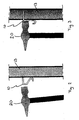
- Figure 2 shows the hanger 10 in a position prior to attachment to the wallboard 13
- Figure 3 shows the hanger subsequent to completed attachment to the wallboard 13.
- a hammer is used for the attachment process.
- the middle tooth 14B is pressed into the wallboard 13 until the two remaining wing tooth elements 14A,14C also get into contact with the wallboard 13.
- both the ends of the tooth elements 14 and the bent portion 21 between the straight part 16 and the bent part of the hook part 17 will rest against the surface of the wallboard 13. This will enhance the attachment of the hanger 10 to the wallboard 13, whereby the hammer easily may be employed for hitting the surface of the intermediate hook portion 15, forcing the tooth elements 14 into the wallboard.
- the straight part 16 with the bent hook part 17 is bent upwards, for example by applying a screw driver or similar tools, until the hanger body 10 is projecting more or less perpendicular out of the wallboard 13.
- the straightened part of the hanger body 10 may then easily pulled out by hand or applying any tool suitable for such operation.
- the weakening part 19 in the transition zone between the flat plate surface 15 and the straight part 16 may be formed by the lateral constriction of material. It should be appreciated, however, that the weakened part 19 also may be obtained in different ways, for example by making a laterally extending weakening line instead of or in addition to said constriction. It should be ensured, however, that the weakening line in the hook is dimensioned in such way that the material failure is avoided when the hook is forced into the wallboard 13 or when the hanger 10 is bent for removal.
- hanger 10 is particularly suited for use in connection with attachment to wallboards, for example made of gypsum, it should be appreciated that the hanger also may be attached to other types of wall surfaces and for other purposes than functioning as hook for pictures, paintings or the like.
Landscapes
- Engineering & Computer Science (AREA)
- General Engineering & Computer Science (AREA)
- Mechanical Engineering (AREA)
- Finishing Walls (AREA)
- Supports Or Holders For Household Use (AREA)
Claims (8)
- Aufhänger (10) zum Befestigen an einer Wandtafel (13), die vorzugsweise aus Gips oder ähnlichem hergestellt ist, umfassend einen intermediären flachen Plattenabschnitt (15), der an einem Ende mit einem Befestigungsmittel (11) versehen ist, das dazu bestimmt ist, in die Wandtafel (13) gedrückt zu werden, wobei das Befestigungsmittel (11) Befestigungszahnelemente (14A, 14B, 14C) umfasst, und wobei der intermediäre flache Plattenabschnitt (15) an seinem entgegengesetzten Ende mit einem hakenförmigen Körper (12) versehen ist, um Gegenstände aufzuhängen, wobei der hakenförmige Körper (12) einen im Wesentlichen flachen und geraden Abschnitt (16) umfasst, der angrenzend an den flachen Plattenabschnitt (15) und einen gebogenen Hakenabschnitt (17) positioniert ist, wobei der Aufhänger (10), in seinem unbefestigten Zustand, im Wesentlichen "S"-förmig ist, wobei das Befestigungsmittel (11) einen im Wesentlichen geraden Abschnitt aufweist, wobei der flache Plattenabschnitt (15) einen Winkel von ungefähr 90° mit dem Befestigungsmittel und einen stumpfen Winkel mit dem flachen und geraden Abschnitt (16) bildet, so dass der stumpfe Winkel beim Anbringen oder Pressen des Befestigungsmittels (11) an der/die Wandtafel gerade gebogen wird, dadurch gekennzeichnet, dass:drei Zahnelemente (14A, 14B, 14C) vorhanden sind, von denen die zwei seitlichen Zahnelemente (14A, 14C) säbelförmig sind, so dass die zwei seitlichen Zahnelemente (14A, 14C) seitwärts gebogen werden, wenn der Aufhänger an einer Wandtafel (13) befestigt wird, und der Fuß jedes seitlichen Zahnelements (14A, 14C) mit einer Einkerbung (18) versehen ist, um das seitwärtse Biegen der seitlichen Zahnelemente (14A, 14C) zu verbessern.
- Aufhänger (10) nach Anspruch 1, wobei der Übergang zwischen dem flachen Plattenabschnitt (15) und dem hakenförmigen Körper (12) einen geschwächten Teil (19) einschließt.
- Aufhänger (10) nach Anspruch 2, wobei der geschwächte Teil (19) konfiguriert ist, um ein Biegen des Aufhängers (10) beim Befestigen an der Wandtafel (13) zu verbessern.
- Aufhänger (10) nach Anspruch 2 oder 3, wobei der geschwächte Teil (19) durch den hakenförmigen Körper (12), der mit einem Abschnitt mit einem verjüngten Materialquerschnittsbereich gebildet wird.
- Aufhänger (10) nach einem der Ansprüche 2 bis 4; wobei der geschwächte Teil (19) die Form einer geschwächten Linie, die sich schräg in Bezug auf die Längsrichtung des Aufhängers (10) erstreckt.
- Aufhänger (10) nach einem der vorhergehenden Ansprüche, wobei der flache Plattenabschnitt (15) dazu bestimmt ist, als Prallwand zu fungieren, wenn der Aufhänger (10) an der Wandtafel (13) angebracht wird.
- Aufhänger (10) nach einem der vorhergehenden Ansprüche, wobei das mittlere Zahnelement (14B) länger ist als die übrigen zwei seitlichen Zahnelemente (14A, 14C), wodurch das mittlere Zahnelement (14B) als Führungsstift fungiert, wenn der Haken (10) an die Wandtafel (13) angebracht wird.
- Aufhänger (10) nach einem der vorhergehenden Ansprüche, wobei der Aufhänger (10) so konfiguriert ist, dass der flache Plattenabschnitt (15) mehr oder weniger parallel zu der Wandtafel (13) in der Ausgangsphase des Installationsverfahrens angeordnet ist.
Priority Applications (1)
| Application Number | Priority Date | Filing Date | Title |
|---|---|---|---|
| PL06253012T PL1733656T3 (pl) | 2005-06-15 | 2006-06-12 | Wieszak do podtrzymywania |
Applications Claiming Priority (1)
| Application Number | Priority Date | Filing Date | Title |
|---|---|---|---|
| NO20052910A NO20052910A (no) | 2005-06-15 | 2005-06-15 | Veggkrok |
Publications (2)
| Publication Number | Publication Date |
|---|---|
| EP1733656A1 EP1733656A1 (de) | 2006-12-20 |
| EP1733656B1 true EP1733656B1 (de) | 2012-06-20 |
Family
ID=35295088
Family Applications (1)
| Application Number | Title | Priority Date | Filing Date |
|---|---|---|---|
| EP06253012A Active EP1733656B1 (de) | 2005-06-15 | 2006-06-12 | Aufhänger |
Country Status (4)
| Country | Link |
|---|---|
| EP (1) | EP1733656B1 (de) |
| DK (1) | DK1733656T3 (de) |
| NO (1) | NO20052910A (de) |
| PL (1) | PL1733656T3 (de) |
Family Cites Families (8)
| Publication number | Priority date | Publication date | Assignee | Title |
|---|---|---|---|---|
| GB190928289A (en) * | 1909-12-03 | 1910-05-19 | Ivan August Mauritz Larsson | Improved Means for Hanging Pictures and the like. |
| GB191208810A (en) * | 1912-04-13 | 1913-04-10 | Howell Davis Thomas | Improved Device for Hanging Pictures and other Objects upon a Wall or other Support. |
| CH497882A (fr) * | 1969-10-31 | 1970-10-31 | Sechaud Jean Jacques | Crochet de suspension murale, notamment pour gravures et tableaux |
| US3966157A (en) * | 1973-11-06 | 1976-06-29 | Jose Corral | Heavy weight hanger |
| US4017048A (en) * | 1974-07-16 | 1977-04-12 | Coats & Clark Inc. | Method of forming a push pin article and articles produced by the method |
| US4040149A (en) * | 1974-07-16 | 1977-08-09 | Coats & Clark, Inc. | Mounting eye |
| SE431505B (sv) * | 1983-06-02 | 1984-02-13 | Sundstroem Fred | Don for upphengning av foremal pa vegg |
| NO306363B1 (no) * | 1998-03-19 | 1999-10-25 | Thor Gunnar Pettersen | Klammer |
-
2005
- 2005-06-15 NO NO20052910A patent/NO20052910A/no unknown
-
2006
- 2006-06-12 EP EP06253012A patent/EP1733656B1/de active Active
- 2006-06-12 DK DK06253012.6T patent/DK1733656T3/da active
- 2006-06-12 PL PL06253012T patent/PL1733656T3/pl unknown
Also Published As
| Publication number | Publication date |
|---|---|
| DK1733656T3 (da) | 2012-09-24 |
| PL1733656T3 (pl) | 2012-12-31 |
| NO20052910D0 (no) | 2005-06-15 |
| NO322830B1 (no) | 2006-12-11 |
| NO20052910A (no) | 2006-12-11 |
| EP1733656A1 (de) | 2006-12-20 |
Similar Documents
| Publication | Publication Date | Title |
|---|---|---|
| CA2188820C (en) | Press-on corner bead | |
| EP2302228B1 (de) | Maueranker | |
| US4500238A (en) | Hollow wall anchor | |
| ITVR20130040A1 (it) | Struttura metallica di supporto di un controsoffitto. | |
| US6119431A (en) | Method of moving heavy materials | |
| US8789810B2 (en) | Decking and plank removal tool | |
| EP1733656B1 (de) | Aufhänger | |
| US3995825A (en) | Form tie for concrete form structures | |
| JP4478514B2 (ja) | 木造建築用連結金物 | |
| US4569172A (en) | Interior corner construction for wallboard, ceiling and partition panel assemblies, and backer clips therefor | |
| US2365971A (en) | Method of making downspout hooks and article formed thereby | |
| US9440279B2 (en) | Punch for crimping tool, and crimping tool provided with such a punch | |
| EP2085531A2 (de) | Deckenrahmen zum Halten von Deckenplatten mit einer Querschiene mit lokal aufgedrücktem Ansatzteil | |
| KR20160149895A (ko) | 부채살 돌출형 기능성 앙카볼트 | |
| JP2006027809A (ja) | H鋼吊りフック | |
| KR200293493Y1 (ko) | 건축용 석재 고정장치 | |
| CA2518085A1 (en) | Wall anchor | |
| US9999914B2 (en) | Punch for crimping tool and crimping tool provided with such a punch | |
| EP2390060B1 (de) | Brechwerkzeug | |
| US799948A (en) | Securing device. | |
| KR20190002120U (ko) | 앙카 펀치 | |
| JP2001027007A (ja) | 天井吊り具とその取付方法 | |
| EP1795767A1 (de) | Ausdehnungsschraube | |
| KR20090051298A (ko) | 안전 수공구 | |
| JPS642060Y2 (de) |
Legal Events
| Date | Code | Title | Description |
|---|---|---|---|
| PUAI | Public reference made under article 153(3) epc to a published international application that has entered the european phase |
Free format text: ORIGINAL CODE: 0009012 |
|
| AK | Designated contracting states |
Kind code of ref document: A1 Designated state(s): AT BE BG CH CY CZ DE DK EE ES FI FR GB GR HU IE IS IT LI LT LU LV MC NL PL PT RO SE SI SK TR |
|
| AX | Request for extension of the european patent |
Extension state: AL BA HR MK YU |
|
| AKX | Designation fees paid | ||
| 17P | Request for examination filed |
Effective date: 20070614 |
|
| RBV | Designated contracting states (corrected) |
Designated state(s): AT BE BG CH CY CZ DE DK EE ES FI FR GB GR HU IE IS IT LI LT LU LV MC NL PL PT RO SE SI SK TR |
|
| REG | Reference to a national code |
Ref country code: DE Ref legal event code: 8566 |
|
| 17Q | First examination report despatched |
Effective date: 20101130 |
|
| GRAP | Despatch of communication of intention to grant a patent |
Free format text: ORIGINAL CODE: EPIDOSNIGR1 |
|
| GRAS | Grant fee paid |
Free format text: ORIGINAL CODE: EPIDOSNIGR3 |
|
| GRAA | (expected) grant |
Free format text: ORIGINAL CODE: 0009210 |
|
| AK | Designated contracting states |
Kind code of ref document: B1 Designated state(s): AT BE BG CH CY CZ DE DK EE ES FI FR GB GR HU IE IS IT LI LT LU LV MC NL PL PT RO SE SI SK TR |
|
| REG | Reference to a national code |
Ref country code: GB Ref legal event code: FG4D |
|
| REG | Reference to a national code |
Ref country code: CH Ref legal event code: EP |
|
| REG | Reference to a national code |
Ref country code: AT Ref legal event code: REF Ref document number: 562534 Country of ref document: AT Kind code of ref document: T Effective date: 20120715 |
|
| REG | Reference to a national code |
Ref country code: IE Ref legal event code: FG4D |
|
| REG | Reference to a national code |
Ref country code: DE Ref legal event code: R096 Ref document number: 602006030280 Country of ref document: DE Effective date: 20120823 |
|
| REG | Reference to a national code |
Ref country code: DK Ref legal event code: T3 |
|
| REG | Reference to a national code |
Ref country code: SE Ref legal event code: TRGR |
|
| REG | Reference to a national code |
Ref country code: NL Ref legal event code: T3 |
|
| PG25 | Lapsed in a contracting state [announced via postgrant information from national office to epo] |
Ref country code: LT Free format text: LAPSE BECAUSE OF FAILURE TO SUBMIT A TRANSLATION OF THE DESCRIPTION OR TO PAY THE FEE WITHIN THE PRESCRIBED TIME-LIMIT Effective date: 20120620 |
|
| REG | Reference to a national code |
Ref country code: LT Ref legal event code: MG4D Effective date: 20120620 |
|
| PG25 | Lapsed in a contracting state [announced via postgrant information from national office to epo] |
Ref country code: SI Free format text: LAPSE BECAUSE OF FAILURE TO SUBMIT A TRANSLATION OF THE DESCRIPTION OR TO PAY THE FEE WITHIN THE PRESCRIBED TIME-LIMIT Effective date: 20120620 Ref country code: LV Free format text: LAPSE BECAUSE OF FAILURE TO SUBMIT A TRANSLATION OF THE DESCRIPTION OR TO PAY THE FEE WITHIN THE PRESCRIBED TIME-LIMIT Effective date: 20120620 Ref country code: GR Free format text: LAPSE BECAUSE OF FAILURE TO SUBMIT A TRANSLATION OF THE DESCRIPTION OR TO PAY THE FEE WITHIN THE PRESCRIBED TIME-LIMIT Effective date: 20120921 |
|
| REG | Reference to a national code |
Ref country code: PL Ref legal event code: T3 |
|
| PG25 | Lapsed in a contracting state [announced via postgrant information from national office to epo] |
Ref country code: CZ Free format text: LAPSE BECAUSE OF FAILURE TO SUBMIT A TRANSLATION OF THE DESCRIPTION OR TO PAY THE FEE WITHIN THE PRESCRIBED TIME-LIMIT Effective date: 20120620 Ref country code: IS Free format text: LAPSE BECAUSE OF FAILURE TO SUBMIT A TRANSLATION OF THE DESCRIPTION OR TO PAY THE FEE WITHIN THE PRESCRIBED TIME-LIMIT Effective date: 20121020 Ref country code: EE Free format text: LAPSE BECAUSE OF FAILURE TO SUBMIT A TRANSLATION OF THE DESCRIPTION OR TO PAY THE FEE WITHIN THE PRESCRIBED TIME-LIMIT Effective date: 20120620 Ref country code: RO Free format text: LAPSE BECAUSE OF FAILURE TO SUBMIT A TRANSLATION OF THE DESCRIPTION OR TO PAY THE FEE WITHIN THE PRESCRIBED TIME-LIMIT Effective date: 20120620 Ref country code: CY Free format text: LAPSE BECAUSE OF FAILURE TO SUBMIT A TRANSLATION OF THE DESCRIPTION OR TO PAY THE FEE WITHIN THE PRESCRIBED TIME-LIMIT Effective date: 20120620 Ref country code: BE Free format text: LAPSE BECAUSE OF FAILURE TO SUBMIT A TRANSLATION OF THE DESCRIPTION OR TO PAY THE FEE WITHIN THE PRESCRIBED TIME-LIMIT Effective date: 20120620 Ref country code: SK Free format text: LAPSE BECAUSE OF FAILURE TO SUBMIT A TRANSLATION OF THE DESCRIPTION OR TO PAY THE FEE WITHIN THE PRESCRIBED TIME-LIMIT Effective date: 20120620 |
|
| PG25 | Lapsed in a contracting state [announced via postgrant information from national office to epo] |
Ref country code: PT Free format text: LAPSE BECAUSE OF FAILURE TO SUBMIT A TRANSLATION OF THE DESCRIPTION OR TO PAY THE FEE WITHIN THE PRESCRIBED TIME-LIMIT Effective date: 20121022 |
|
| PLBE | No opposition filed within time limit |
Free format text: ORIGINAL CODE: 0009261 |
|
| STAA | Information on the status of an ep patent application or granted ep patent |
Free format text: STATUS: NO OPPOSITION FILED WITHIN TIME LIMIT |
|
| PG25 | Lapsed in a contracting state [announced via postgrant information from national office to epo] |
Ref country code: ES Free format text: LAPSE BECAUSE OF FAILURE TO SUBMIT A TRANSLATION OF THE DESCRIPTION OR TO PAY THE FEE WITHIN THE PRESCRIBED TIME-LIMIT Effective date: 20121001 |
|
| 26N | No opposition filed |
Effective date: 20130321 |
|
| REG | Reference to a national code |
Ref country code: DE Ref legal event code: R097 Ref document number: 602006030280 Country of ref document: DE Effective date: 20130321 |
|
| PG25 | Lapsed in a contracting state [announced via postgrant information from national office to epo] |
Ref country code: BG Free format text: LAPSE BECAUSE OF FAILURE TO SUBMIT A TRANSLATION OF THE DESCRIPTION OR TO PAY THE FEE WITHIN THE PRESCRIBED TIME-LIMIT Effective date: 20120920 |
|
| PG25 | Lapsed in a contracting state [announced via postgrant information from national office to epo] |
Ref country code: MC Free format text: LAPSE BECAUSE OF FAILURE TO SUBMIT A TRANSLATION OF THE DESCRIPTION OR TO PAY THE FEE WITHIN THE PRESCRIBED TIME-LIMIT Effective date: 20120620 |
|
| REG | Reference to a national code |
Ref country code: CH Ref legal event code: PL |
|
| REG | Reference to a national code |
Ref country code: IE Ref legal event code: MM4A |
|
| PG25 | Lapsed in a contracting state [announced via postgrant information from national office to epo] |
Ref country code: IE Free format text: LAPSE BECAUSE OF NON-PAYMENT OF DUE FEES Effective date: 20130612 Ref country code: CH Free format text: LAPSE BECAUSE OF NON-PAYMENT OF DUE FEES Effective date: 20130630 Ref country code: LI Free format text: LAPSE BECAUSE OF NON-PAYMENT OF DUE FEES Effective date: 20130630 |
|
| PG25 | Lapsed in a contracting state [announced via postgrant information from national office to epo] |
Ref country code: TR Free format text: LAPSE BECAUSE OF FAILURE TO SUBMIT A TRANSLATION OF THE DESCRIPTION OR TO PAY THE FEE WITHIN THE PRESCRIBED TIME-LIMIT Effective date: 20120620 |
|
| PG25 | Lapsed in a contracting state [announced via postgrant information from national office to epo] |
Ref country code: LU Free format text: LAPSE BECAUSE OF NON-PAYMENT OF DUE FEES Effective date: 20130612 Ref country code: HU Free format text: LAPSE BECAUSE OF FAILURE TO SUBMIT A TRANSLATION OF THE DESCRIPTION OR TO PAY THE FEE WITHIN THE PRESCRIBED TIME-LIMIT; INVALID AB INITIO Effective date: 20060612 |
|
| REG | Reference to a national code |
Ref country code: FR Ref legal event code: PLFP Year of fee payment: 11 |
|
| REG | Reference to a national code |
Ref country code: FR Ref legal event code: PLFP Year of fee payment: 12 |
|
| REG | Reference to a national code |
Ref country code: FR Ref legal event code: PLFP Year of fee payment: 13 |
|
| P01 | Opt-out of the competence of the unified patent court (upc) registered |
Effective date: 20230330 |
|
| PGFP | Annual fee paid to national office [announced via postgrant information from national office to epo] |
Ref country code: NL Payment date: 20250520 Year of fee payment: 20 |
|
| PGFP | Annual fee paid to national office [announced via postgrant information from national office to epo] |
Ref country code: FI Payment date: 20250520 Year of fee payment: 20 |
|
| PGFP | Annual fee paid to national office [announced via postgrant information from national office to epo] |
Ref country code: PL Payment date: 20250522 Year of fee payment: 20 Ref country code: DE Payment date: 20250520 Year of fee payment: 20 |
|
| PGFP | Annual fee paid to national office [announced via postgrant information from national office to epo] |
Ref country code: GB Payment date: 20250520 Year of fee payment: 20 Ref country code: DK Payment date: 20250520 Year of fee payment: 20 |
|
| PGFP | Annual fee paid to national office [announced via postgrant information from national office to epo] |
Ref country code: IT Payment date: 20250520 Year of fee payment: 20 |
|
| PGFP | Annual fee paid to national office [announced via postgrant information from national office to epo] |
Ref country code: FR Payment date: 20250520 Year of fee payment: 20 |
|
| PGFP | Annual fee paid to national office [announced via postgrant information from national office to epo] |
Ref country code: AT Payment date: 20250522 Year of fee payment: 20 |
|
| PGFP | Annual fee paid to national office [announced via postgrant information from national office to epo] |
Ref country code: SE Payment date: 20250520 Year of fee payment: 20 |