EP1732470B1 - Systeme d'introduction d'endoprothese vasculaire - Google Patents
Systeme d'introduction d'endoprothese vasculaire Download PDFInfo
- Publication number
- EP1732470B1 EP1732470B1 EP05733174A EP05733174A EP1732470B1 EP 1732470 B1 EP1732470 B1 EP 1732470B1 EP 05733174 A EP05733174 A EP 05733174A EP 05733174 A EP05733174 A EP 05733174A EP 1732470 B1 EP1732470 B1 EP 1732470B1
- Authority
- EP
- European Patent Office
- Prior art keywords
- introducer
- stent
- kit
- catheter
- wire guide
- Prior art date
- Legal status (The legal status is an assumption and is not a legal conclusion. Google has not performed a legal analysis and makes no representation as to the accuracy of the status listed.)
- Active
Links
- 210000003484 anatomy Anatomy 0.000 claims abstract description 8
- 238000000034 method Methods 0.000 abstract description 8
- 210000003459 common hepatic duct Anatomy 0.000 description 25
- 210000001953 common bile duct Anatomy 0.000 description 20
- 210000003445 biliary tract Anatomy 0.000 description 12
- 239000000463 material Substances 0.000 description 9
- 208000031481 Pathologic Constriction Diseases 0.000 description 7
- -1 polyethylene Polymers 0.000 description 7
- 229920001343 polytetrafluoroethylene Polymers 0.000 description 6
- 239000004810 polytetrafluoroethylene Substances 0.000 description 6
- 239000004698 Polyethylene Substances 0.000 description 4
- 229920000573 polyethylene Polymers 0.000 description 4
- 239000004677 Nylon Substances 0.000 description 3
- 239000004952 Polyamide Substances 0.000 description 3
- 230000003247 decreasing effect Effects 0.000 description 3
- 239000010410 layer Substances 0.000 description 3
- 229920001778 nylon Polymers 0.000 description 3
- 229920002647 polyamide Polymers 0.000 description 3
- 229920002635 polyurethane Polymers 0.000 description 3
- 239000004814 polyurethane Substances 0.000 description 3
- 239000002356 single layer Substances 0.000 description 3
- 210000001198 duodenum Anatomy 0.000 description 2
- 210000000232 gallbladder Anatomy 0.000 description 2
- 210000001035 gastrointestinal tract Anatomy 0.000 description 2
- 210000000496 pancreas Anatomy 0.000 description 2
- 230000002792 vascular Effects 0.000 description 2
- 238000004026 adhesive bonding Methods 0.000 description 1
- RTZKZFJDLAIYFH-UHFFFAOYSA-N ether Substances CCOCC RTZKZFJDLAIYFH-UHFFFAOYSA-N 0.000 description 1
- 239000012530 fluid Substances 0.000 description 1
- 238000003780 insertion Methods 0.000 description 1
- 230000037431 insertion Effects 0.000 description 1
- 230000002787 reinforcement Effects 0.000 description 1
- 229910001220 stainless steel Inorganic materials 0.000 description 1
- 239000010935 stainless steel Substances 0.000 description 1
- 239000000126 substance Substances 0.000 description 1
Images


Classifications
-
- A—HUMAN NECESSITIES
- A61—MEDICAL OR VETERINARY SCIENCE; HYGIENE
- A61F—FILTERS IMPLANTABLE INTO BLOOD VESSELS; PROSTHESES; DEVICES PROVIDING PATENCY TO, OR PREVENTING COLLAPSING OF, TUBULAR STRUCTURES OF THE BODY, e.g. STENTS; ORTHOPAEDIC, NURSING OR CONTRACEPTIVE DEVICES; FOMENTATION; TREATMENT OR PROTECTION OF EYES OR EARS; BANDAGES, DRESSINGS OR ABSORBENT PADS; FIRST-AID KITS
- A61F2/00—Filters implantable into blood vessels; Prostheses, i.e. artificial substitutes or replacements for parts of the body; Appliances for connecting them with the body; Devices providing patency to, or preventing collapsing of, tubular structures of the body, e.g. stents
- A61F2/95—Instruments specially adapted for placement or removal of stents or stent-grafts
- A61F2/958—Inflatable balloons for placing stents or stent-grafts
-
- A—HUMAN NECESSITIES
- A61—MEDICAL OR VETERINARY SCIENCE; HYGIENE
- A61F—FILTERS IMPLANTABLE INTO BLOOD VESSELS; PROSTHESES; DEVICES PROVIDING PATENCY TO, OR PREVENTING COLLAPSING OF, TUBULAR STRUCTURES OF THE BODY, e.g. STENTS; ORTHOPAEDIC, NURSING OR CONTRACEPTIVE DEVICES; FOMENTATION; TREATMENT OR PROTECTION OF EYES OR EARS; BANDAGES, DRESSINGS OR ABSORBENT PADS; FIRST-AID KITS
- A61F2/00—Filters implantable into blood vessels; Prostheses, i.e. artificial substitutes or replacements for parts of the body; Appliances for connecting them with the body; Devices providing patency to, or preventing collapsing of, tubular structures of the body, e.g. stents
- A61F2/95—Instruments specially adapted for placement or removal of stents or stent-grafts
- A61F2/954—Instruments specially adapted for placement or removal of stents or stent-grafts for placing stents or stent-grafts in a bifurcation
-
- A—HUMAN NECESSITIES
- A61—MEDICAL OR VETERINARY SCIENCE; HYGIENE
- A61F—FILTERS IMPLANTABLE INTO BLOOD VESSELS; PROSTHESES; DEVICES PROVIDING PATENCY TO, OR PREVENTING COLLAPSING OF, TUBULAR STRUCTURES OF THE BODY, e.g. STENTS; ORTHOPAEDIC, NURSING OR CONTRACEPTIVE DEVICES; FOMENTATION; TREATMENT OR PROTECTION OF EYES OR EARS; BANDAGES, DRESSINGS OR ABSORBENT PADS; FIRST-AID KITS
- A61F2/00—Filters implantable into blood vessels; Prostheses, i.e. artificial substitutes or replacements for parts of the body; Appliances for connecting them with the body; Devices providing patency to, or preventing collapsing of, tubular structures of the body, e.g. stents
- A61F2/95—Instruments specially adapted for placement or removal of stents or stent-grafts
- A61F2/962—Instruments specially adapted for placement or removal of stents or stent-grafts having an outer sleeve
- A61F2/97—Instruments specially adapted for placement or removal of stents or stent-grafts having an outer sleeve the outer sleeve being splittable
-
- A—HUMAN NECESSITIES
- A61—MEDICAL OR VETERINARY SCIENCE; HYGIENE
- A61F—FILTERS IMPLANTABLE INTO BLOOD VESSELS; PROSTHESES; DEVICES PROVIDING PATENCY TO, OR PREVENTING COLLAPSING OF, TUBULAR STRUCTURES OF THE BODY, e.g. STENTS; ORTHOPAEDIC, NURSING OR CONTRACEPTIVE DEVICES; FOMENTATION; TREATMENT OR PROTECTION OF EYES OR EARS; BANDAGES, DRESSINGS OR ABSORBENT PADS; FIRST-AID KITS
- A61F2/00—Filters implantable into blood vessels; Prostheses, i.e. artificial substitutes or replacements for parts of the body; Appliances for connecting them with the body; Devices providing patency to, or preventing collapsing of, tubular structures of the body, e.g. stents
- A61F2/02—Prostheses implantable into the body
- A61F2/04—Hollow or tubular parts of organs, e.g. bladders, tracheae, bronchi or bile ducts
- A61F2002/041—Bile ducts
-
- A—HUMAN NECESSITIES
- A61—MEDICAL OR VETERINARY SCIENCE; HYGIENE
- A61F—FILTERS IMPLANTABLE INTO BLOOD VESSELS; PROSTHESES; DEVICES PROVIDING PATENCY TO, OR PREVENTING COLLAPSING OF, TUBULAR STRUCTURES OF THE BODY, e.g. STENTS; ORTHOPAEDIC, NURSING OR CONTRACEPTIVE DEVICES; FOMENTATION; TREATMENT OR PROTECTION OF EYES OR EARS; BANDAGES, DRESSINGS OR ABSORBENT PADS; FIRST-AID KITS
- A61F2/00—Filters implantable into blood vessels; Prostheses, i.e. artificial substitutes or replacements for parts of the body; Appliances for connecting them with the body; Devices providing patency to, or preventing collapsing of, tubular structures of the body, e.g. stents
- A61F2/02—Prostheses implantable into the body
- A61F2/04—Hollow or tubular parts of organs, e.g. bladders, tracheae, bronchi or bile ducts
- A61F2/06—Blood vessels
- A61F2002/065—Y-shaped blood vessels
- A61F2002/067—Y-shaped blood vessels modular
-
- A—HUMAN NECESSITIES
- A61—MEDICAL OR VETERINARY SCIENCE; HYGIENE
- A61F—FILTERS IMPLANTABLE INTO BLOOD VESSELS; PROSTHESES; DEVICES PROVIDING PATENCY TO, OR PREVENTING COLLAPSING OF, TUBULAR STRUCTURES OF THE BODY, e.g. STENTS; ORTHOPAEDIC, NURSING OR CONTRACEPTIVE DEVICES; FOMENTATION; TREATMENT OR PROTECTION OF EYES OR EARS; BANDAGES, DRESSINGS OR ABSORBENT PADS; FIRST-AID KITS
- A61F2250/00—Special features of prostheses classified in groups A61F2/00 - A61F2/26 or A61F2/82 or A61F9/00 or A61F11/00 or subgroups thereof
- A61F2250/0058—Additional features; Implant or prostheses properties not otherwise provided for
- A61F2250/0071—Additional features; Implant or prostheses properties not otherwise provided for breakable or frangible
Definitions
- This invention generally relates to medical devices, and more particularly to devices for delivering stents to a target anatomy.
- Stents are elongate tubes that are used to prop open occluded or narrowed vessels or body lumens. Among other things, stents are often used to maintain the patency of the biliary tree, or common bile duct.
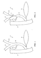
- Figure 1 is a partial, cross-sectional view of a biliary system 2 showing the common bile duct 2a, the left hepatic duct 2b, the right hepatic duct 2c, the gall bladder 2d, the pancreas 2e and the duodenum 2f.
- Figure 2 illustrates a partial cross-sectional view of the biliary system 2 having strictures 3 within the common bile duct 2a, the left hepatic duct 2b and the right hepatic duct 2c.
- One method of establishing proper drainage through the diseased ducts is to prop open the ducts by placing stents, such as self-expanding biliary stents, within the diseased ducts. Because of the branched configuration of the duct anatomy it is often necessary to place two or more stents in an overlying or side-by-side configuration.
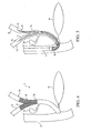
- Figure 3 illustrates the problems associated with the prior art method of placing stents in the common bile duct 2a and the left and right hepatic ducts 2b, 2c. That is, placing stent 16 within the common bile duct 2a and the left hepatic duct 2b impedes subsequent access to the stricture in the right hepatic duct 2c . This prevents placement of a stent in the right hepatic duct 2c.
- Figure 3A illustrates one problem encountered in the prior art by placing two stents sequentially. That is, once the first stent is deployed, it impedes insertion of the second introducer 20 used to deploy the second stent.
- An alternative to sequential deployment of the stents is simultaneous deployment. Simultaneous deployment, however, requires the side-by-side arrangement of two stent introducers within the working channel of an endoscope. Depending on the size of the stents to be placed and the limited size of the working channel of the endoscope, this option may be unworkable.
- a stent delivery system having a first introducer used to deploy a first stent, and a sheath or catheter used to receive a second introducer, which in turn is used to deploy a second stent.
- the first introducer and the catheter can be simultaneously deployed, for example, in a staggered configuration, through the working channel of an endoscope. Once the first stent is deployed, the catheter facilitates delivery of the second introducer to the target anatomy.
- the catheter or sheath is splittable.
- wire guides are used to guide the placement of the first introducer, the catheter, and the second introducer.
- the method includes placing a first and a second wire guide in a working channel of an endoscope.
- the first wire guide is inserted into the first branch lumen of the bifurcation.
- the second wire guide is inserted into the second branch lumen of the bifurcation.
- a first introducer and splittable catheter can then be advanced over the respective wire guides to the respective target anatomies. Once in place, the first stent can be deployed.
- a second introducer can then be introduced over the second guide wire, through the splittable catheter and to the proper target anatomy. Once the second introducer is in place, the second stent can be deployed.
- the method may further include any of the following steps: disposing the first introducer and the splittable catheter within the working channel of the endoscope such that the first introducer proximal portion is disposed adjacent to the splittable catheter and the first introducer distal portion is disposed distal to the splittable catheter while inside the working channel of the endoscope; deploying the first stent within the first branch lumen and the main lumen of the bifurcation and withdrawing the first introducer from the bifurcation; and/or splitting the splittable catheter and withdrawing the splittable catheter from the bifurcation.
- Figure 1 is a partial, cross-sectional view of a biliary system showing the common bile duct, the left hepatic duct, the right hepatic duct, the gall bladder, the pancreas and the duodenum.
- Figure 2 is a partial, cross-sectional view of the biliary system of Figure 1 showing strictures within the common bile duct, the left hepatic duct and the right hepatic duct.
- Figure 3 is a partial, cross-sectional view of the biliary system of Figure 2 illustrating a stent that has been placed in the common bile duct and the left hepatic duct.
- Figure 3A is a partial, cross-sectional view of the biliary system of Figure 1 illustrating a first stent previously placed by a first introducer in the right hepatic duct and the common bile duct that obscures the access of a second introducer attempting to place a second stent in the left hepatic duct and common bile duct.
- Figure 4 is a partial, cross-sectional view of the biliary system of Figure 2 illustrating the placement of first and second stents in the left and right hepatic ducts, respectively, and the common bile duct.
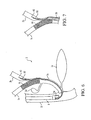
- Figure 5 is a partial, cross-sectional view of a preferred embodiment of the stent delivery system of the present invention illustrating a first introducer placed within the right hepatic duct and the common bile duct and a splittable catheter placed in the right hepatic duct and the common bile duct.
- Figure 6 is a partial, cross-sectional view of the preferred embodiment of the stent delivery system of Figure 5 illustrating a first stent deployed in the right hepatic duct and common bile duct after the first introducer has been removed and the splittable catheter placed in the right hepatic duct and the common bile duct.
- Figure 7 is a partial, cross-sectional view of the preferred embodiment of the stent delivery system of Figure 6 illustrating a first stent deployed in the right hepatic duct and common bile duct and the splittable catheter shielding a second introducer as the second introducer is advanced over a second wire guide into the common bile duct and the left hepatic duct.
- Figure 8 is a cross-sectional, end view of the stent delivery system of the present invention showing the first introducer and the splittable catheter within the working channel of an endoscope.
- Figure 9 is a partial, cross sectional, side-view of a preferred embodiment of the stent delivery system of the present invention showing the first introducer and the splittable catheter within the working channel of an endoscope.
- Figure 10 is a cross-sectional view of an embodiment of the first introducer of the stent delivery system of the present invention.
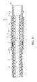
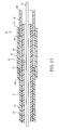
- Figure 11 is a partial, cross-sectional view of a distal portion of the first introducer of Figure 5 .
- Figure 12 is a partial, cross-sectional view of an alternate embodiment of the distal portion of the first introducer of Figure 5 .
- Figure 13 is a partial, cross-sectional view of the distal portion of the first introducer of Figure 5 showing the wire guide and wire guide lumen.
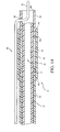
- Figure 14 is a partial, cross-sectional view of the distal portion of the first introducer of Figure 5 showing an alternate embodiment of the wire guide and the wire guide lumen.
- Figure 15 is a partial, cross-sectional view of the distal portion of the first introducer of Figure 5 showing an alternate embodiment of the wire guide and the wire guide lumen.
- FIGS 1-2 and 4 a bifurcation having a main lumen, a first branch lumen and a second branch lumen.
- FIGs 1-2 and 4 illustrate a bifurcation in the biliary system, wherein the main lumen comprises the common bile duct 2a and the first and second branch lumens comprise the left and right hepatic ducts 2b, 2c respectively.
- Figure 1 shows a normal, or healthy, biliary system without strictures.
- Figure 2 shows the biliary system with strictures 3 residing in the main lumen and in both branch lumens of the bifurcation.
- Figure 4 shows a pair of stents placed in the left and right hepatic ducts 2b, 2c, respectively, and the common bile duct 2a.
- Stent delivery system 1 includes a first introducer 10 having a first stent 16, a second introducer 20 comprising a second stent 26 and a splittable catheter 50.
- the first introducer 10 and the splittable catheter 50 are adapted to be disposed within the working channel 8a of an endoscope 8 as shown in Figures 5 , 8 and 9 .
- Figure 7 illustrates, the splittable catheter 50 comprises an inner diameter through which the second introducer is advanced.
- the stent delivery system 1 may also include first and second wire guides 32, 42 as illustrated in Figure 5 .
- the splittable catheter 50 comprises an inner diameter and an outer diameter.
- the splittable catheter 50 inner diameter is adapted to receive the second introducer 20 as best seen in Figure 7 .
- Splittable catheter 50 can be made from any suitable material known in the art including, but not limited to, PTFE, polyamide, polyurethane, polyethylene and nylon including multi-layer or single layer structures.
- the splittable catheter 50 can be constructed of a splittable material, i.e. a material that readily tears in a longitudinal direction along the length of the sheath.
- splittable material is a molecularly oriented (non-isotropic) polytetrafluoroethylene (PTFE) such as that used in the PEEL-AWAYTM Sheath (Cook Incorporated, Bloomington, Ind.).
- PTFE molecularly oriented polytetrafluoroethylene
- the splittable catheter 50 comprises a groove, pre-score, a weakened area or a pre-slit end to facilitate splitting.
- splittable catheter 50 ranges in size from about 1,67 mm (5 Fr.) to about 3 mm (9 Fr). These sizes are provided for illustrative purposes only and are not intended to be construed as a limitation of the present invention.
- the size of the splittable catheter 50 is related to the size of the second introducer 20 that is advanced through it, which in turn is related to the size of the second stent 26 in its compressed or unexpanded configuration.
- splittable catheters smaller than about 1,67 mm (5 Fr). that may become available in the future are contemplated as being within the scope of the claims of the invention.
- any introducer capable of introducing and deploying stents is contemplated.
- Non-limiting examples include biliary stent deployment delivery systems as well as the introducers described in co-pending application number US-2005-0125050 A1 .
- the first and second introducers 10, 20 may be of the same or different type and size.
- introducer 10 has a proximal end and a distal end and comprises inner and outer coaxial tubes.
- the outer coaxial tube forms an outer catheter, or sheath, 11.
- the inner coaxial tube forms a shaft 13.
- Shaft 13 has a proximal end 13a, a distal end 13b and a stent retaining area 15.
- shaft 13 may include a pusher band 17 attached to the stent retaining area 15, a distal tip 18 attached to the shaft distal end 13b and a wire guide lumen 19.
- Shaft 13 can be made from any suitable material known in the art including, but not limited to, polyethylene ether ketone (PEEK), polytetrafluoroethylene (PTFE), polyamide, polyurethane, polyethylene and nylon, including multi-layer or single layer structures and may also include reinforcement wires, braid wires, coils and or filaments.
- shaft 13 comprises a proximal portion made of a relatively rigid material such as stainless steel or any other suitable material known in the art.
- Stent retaining area 15 is preferably located on a distal portion of the shaft 13.
- the stent retaining area 15 retains a stent 16 to be deployed in the bifurcation.
- stent 16 is a self-expanding stent.
- Pusher band 17 helps to prevent the stent from proximally migrating as the outer catheter 11 is withdrawn proximally to deploy the stent.
- the pusher band 17 is located proximal to the stent 16 such that the proximal end of the stent 16 abuts the pusher band 17 as shown in Figures 10-15 .
- Distal tip 18 helps prevent fluids from entering the outer catheter 11 as the introducer 10 is navigated through the body lumens. As shown in Figures 10-15 , distal tip 18 has a proximal end 18a and a distal end 18b. The distal tip proximal end 18a has a diameter that is less than the diameter of the distal outer catheter distal end 14b and is received therein. Optionally, the distal tip 18 tapers to a smaller diameter towards its distal end 18b as shown in Figure 12 . Distal tip 18 can be made from any suitable material known in the art including, but not limited to, PEEK, PTFE, polyamide, polyurethane, polyethylene and nylon, including multi-layer or single layer structures.
- wire guide lumen 19 extends through the shaft 13, from the shaft distal end 13b to the shaft proximal end 13a.
- the shaft proximal end 13a optionally includes a luer-lock fitting 31 for releaseably fixing a wire guide 32 relative to shaft 13 as shown in Figure 10 .
- the stent delivery system 1 of the present invention includes an over-the-wire type wire guide. Such wire guides are known in the art.
- the wire guide lumen 19 may extend through the shaft 13 from the shaft distal end 13b to the shaft proximal end 13a but the wire guide 32 exits through an aperture positioned along the length of the introducer 10.
- the wire guide 32 extends through a portion of the distal tip 18 and exits through an aperture 30 positioned along the length of the distal tip 18.
- the wire guide 32 extends through the distal tip 18 and exits the introducer 10 without passing through stent 16.
- wire guide 32 may extend proximally through distal tip 18 for a distance of about I cm.
- the wire guide lumen 19 extends through the length of the shaft 13 but the wire guide 32 extends through a portion of the shaft 13 and exits through an aperture 30 positioned along the length of outer catheter 11.
- wire guide 32 extends through the distal tip 18, through a portion of the shaft 13 and passes through stent 16 before exiting introducer 10.
- wire guide 32 may extend through the distal tip 18 and through the stent retaining area 15 for a distance of about 20 cm.
- the wire guide lumen 19 may extend through a portion of shaft 13 and may exit through an aperture 30 positioned along the length of the introducer 10. Any number of apertures 30 positioned at any location along the length of the introducer 10 is contemplated.
- the wire guide lumen 19 may also comprise a channel or split.
- Aperture 30 provides the stent delivery system of the present invention with rapid-exchange capabilities.
- the delivery system can be removed from a wire guide 32 having a length substantially shorter than the length necessary if the wire guide 32 were extended through the entire length of the wire guide lumen 19.
- the sheath, or outer catheter 11 has a proximal end 11a and a distal end 11b.
- at least the distal portion of outer catheter 11 is made of any optically clear or imageable material so that the stent 16 mounted on the stent retaining area 15 of the shaft 13 can be viewed.
- the outer catheter 11 further includes a proximal outer catheter 12 having proximal and distal ends, 12a and 12b, respectively, and a distal outer catheter 14 having proximal and distal ends, 14a and 14b, respectively.
- the distal end 12b of the proximal outer catheter 12 is attached to the proximal end 14a of the distal outer catheter 14 to form outer catheter 11.
- proximal outer catheter 12 can be attached to the proximal end 14a of distal outer catheter 14 by any method known in the art including, but not limited to, heat fusing, adhesive bonding, chemical bonding or mechanical fitting.
- the proximal outer catheter 12, and the distal outer catheter 14 can be formed from of a single catheter or sheath.
- the first introducer proximal outer diameter is about 1,67 mm (5 Fr.) to about 2 mm (6 Fr.) and the first introducer distal outer diameter is about 2 mm (6 Fr.) to about 2,17 mm (6.5 Fr.) to place a first stent 16 having a compressed diameter of about 1,96 mm (0.077 inches) to about 1,98 cm (0.78 inches).
- the size of the introducer required to place a stent is related to the size of the stent to be placed, and more particularly, to the size of the compressed configuration of the stent.
- introducers having distal outer diameters less than about 2 mm (6 Fr.) used to place stents having compressed configurations less than about 1,98 cm (0.078 inches) that may become available in the future are contemplated as being within the scope of the claims of the invention.
- the first introducer 10 and the splittable catheter 50 are sized to be disposed next to each other in the working channel 8a of an endoscope 8. More particularly, the sum of the first introducer 10 outer diameter (i.e. either the proximal outer diameter or the distal outer diameter) and the splittable catheter outer diameter is less than the inner diameter of the working channel 8a of the endoscope 8.
- the first introducer 10 and the splittable catheter 50 are disposed next to each other in a staggered configuration within the working channel 8a of an endoscope 8. That is, the introducer has an increased diameter portion (the stent retaining area) and a decreased diameter portion (the proximal outer catheter). Likewise, the splittable catheter has an increased diameter portion (the stent retaining area) and a decreased diameter portion (the proximal outer catheter). When the introducer catheter are positioned in an endoscope adjacent to one another, and staggered, the respective increased and decreased diameter portions are nested together. As can be seen in Figure 9 , the sum of the first introducer proximal outer diameter and the splittable catheter 50 is less than the inner diameter of the working channel 8a of the endoscope 8.
- the first introducer 10 and the splittable catheter 50 are sized to also accommodate at least one wire guide 32, 42 within the working channel 8a of the endoscope 8.
- the sum of the first introducer proximal outer diameter, the splittable catheter outer diameter and at least one of the first and second wire guides 32, 42 is less than the inner diameter of the working channel 8a of the endoscope 8.
- the stent delivery system 1 of the present invention is used to place first and second stents 16, 26 into a bifurcation having strictures 3 in the main lumen 2a and the first and second branch lumens 2b, 2c as follows.
- a distal end of a first wire guide is advanced into the first branch lumen of the bifurcation and a distal end of a second wire guide is advanced into the second branch lumen of the bifurcation.
- the first introducer 10 and the splittable catheter 50 are inserted over the guide wire into the working channel 8a of the endoscope 8.
- the first introducer 10 is positioned within the first branch of the bifurcation and the splittable catheter 50 is positioned within the second branch lumen of the bifurcation, as shown in Figure 5 .
- the first introducer 10 and splittable catheter 50 may be positioned sequentially or simultaneously.
- the first introducer 10 is positioned such that the first stent 16 is at least partially aligned within any occlusion of narrowing of the first branch of the bifurcation. Once aligned, the first stent is deployed within the first branch of the bifurcation and the first introducer is withdrawn as shown in Figure 6 .
- a second introducer 20 is passed through the working channel 8a of the endoscope 8 and advanced over the second wire guide 42 through the splittable catheter 50.
- Figure 7 shows that the splittable catheter 50 acts as a shield to protect the second introducer 20 from being snagged, or otherwise blocked, by the deployed first stent 16.
- Figure 7 also shows the splittable catheter 50 splitting, or peeling away, as the second introducer 20 is advanced through it and into the second branch lumen 26.
- the splittable catheter 50 is removed and the second stent 26 is deployed within the second branch lumen 2b and the main lumen 2a. The resulting connfiguration is shown at Figure 4 .
Claims (14)
- Kit pour acheminer des première et deuxième endoprothèses vasculaires à une anatomie cible bifurquée, le kit comprenant :un premier dispositif d'introduction (10), comprenant :un corps tubulaire ayant une extrémité proximale, une extrémité distale et une portion de support d'endoprothèse vasculaire située entre elles ;un deuxième dispositif d'introduction (20) comprenant :un corps tubulaire ayant une extrémité proximale, une extrémité distale et une portion de support d'endoprothèse vasculaire située entre elles ;un cathéter (50) prévu pour recevoir le deuxième dispositif d'introduction, le cathéter ayant une paroi cassable ;un emballage stérile prévu pour recevoir le premier dispositif d'introduction (10), le deuxième dispositif d'introduction (20) et le cathéter (50), et caractérisé en ce que le kit comprend :un endoscope (8) comprenant un canal de travail (8a) ;le premier dispositif d'introduction (10) et le cathéter (50) étant dimensionnés de manière à être disposés l'un à côté de l'autre dans le canal de travail (8a) de l'endoscope (8).
- Kit selon la revendication 1, comprenant en outre:une première endoprothèse vasculaire (16) positionnée dans la portion de support d'endoprothèse vasculaire du premier dispositif d'introduction (10) ; etune deuxième endoprothèse vasculaire (26) positionnée dans la portion de support d'endoprothèse vasculaire du deuxième dispositif d'introduction (20).
- Kit selon la revendication 1 ou 2, comprenant en outre :un premier fil-guide (32), le premier fil-guide étant configuré pour recevoir le premier dispositif d'introduction (10), et un deuxième fil-guide (42), le deuxième fil-guide étant configuré pour recevoir le deuxième dispositif d'introduction (20), l'emballage stérile étant prévu pour recevoir les premier et deuxième fils-guides (32, 42).
- Kit selon la revendication 1 ou 2, dans lequel le premier dispositif d'introduction (10) comprend en outre :un passage s'étendant entre l'extrémité distale et un orifice (30) situé à proximité de la portion de support d'endoprothèse vasculaire, l'orifice étant prévu pour recevoir un fil-guide.
- Kit selon la revendication 1 ou 2, dans lequel le deuxième dispositif d'introduction comprend en outre :un passage s'étendant entre l'extrémité distale et un orifice (30) positionné à proximité de la portion de support d'endoprothèse vasculaire, l'orifice étant prévu pour recevoir un fil-guide.
- Kit selon la revendication 1 ou 2, dans lequel le premier dispositif d'introduction (10) comprend en outre :un passage s'étendant entre l'extrémité distale et un orifice (30) positionné à distance de la portion de support d'endoprothèse vasculaire, l'orifice (30) étant prévu pour recevoir un fil-guide.
- Kit selon la revendication 1 ou 2, dans lequel le deuxième dispositif d'introduction (20) comprend en outre :un passage s'étendant entre l'extrémité distale et un orifice (30) positionné à distance de la portion de support d'endoprothèse vasculaire, l'orifice (30) étant prévu pour recevoir un fil-guide.
- Kit selon la revendication 1, 2 ou 4 à 7, dans lequel le premier dispositif d'introduction (10) et le cathéter (50) sont prévus pour être disposés dans une configuration en partie décalée dans le canal de travail (8a) de l'endoscope (8).
- Kit selon la revendication 2, dans lequel l'endoprothèse vasculaire est auto-extensible.
- Kit selon l'une quelconque des revendications précédentes, dans lequel la paroi cassable comprend un affaiblissement structurel.
- Kit selon la revendication 10, dans lequel l'affaiblissement structurel est une entaille.
- Kit selon la revendication 10, dans lequel l'affaiblissement structurel comprend une fente longitudinale.
- Kit selon la revendication 10, dans lequel l'affaiblissement structurel comprend une fente longitudinale interrompue.
- Kit selon la revendication 10, dans lequel une première portion longitudinale de la paroi cassable a une épaisseur inférieure à l'épaisseur d'une portion adjacente de la paroi longitudinale.
Applications Claiming Priority (2)
| Application Number | Priority Date | Filing Date | Title |
|---|---|---|---|
| US55872104P | 2004-03-31 | 2004-03-31 | |
| PCT/US2005/010904 WO2005096994A1 (fr) | 2004-03-31 | 2005-03-31 | Systeme d'introduction d'endoprothese vasculaire |
Publications (2)
| Publication Number | Publication Date |
|---|---|
| EP1732470A1 EP1732470A1 (fr) | 2006-12-20 |
| EP1732470B1 true EP1732470B1 (fr) | 2010-05-26 |
Family
ID=34964750
Family Applications (1)
| Application Number | Title | Priority Date | Filing Date |
|---|---|---|---|
| EP05733174A Active EP1732470B1 (fr) | 2004-03-31 | 2005-03-31 | Systeme d'introduction d'endoprothese vasculaire |
Country Status (6)
| Country | Link |
|---|---|
| US (2) | US20050273150A1 (fr) |
| EP (1) | EP1732470B1 (fr) |
| JP (1) | JP4714736B2 (fr) |
| AT (1) | ATE468830T1 (fr) |
| DE (1) | DE602005021473D1 (fr) |
| WO (1) | WO2005096994A1 (fr) |
Families Citing this family (18)
| Publication number | Priority date | Publication date | Assignee | Title |
|---|---|---|---|---|
| US8034100B2 (en) | 1999-03-11 | 2011-10-11 | Endologix, Inc. | Graft deployment system |
| US6261316B1 (en) | 1999-03-11 | 2001-07-17 | Endologix, Inc. | Single puncture bifurcation graft deployment system |
| AU2008286878A1 (en) * | 2007-08-15 | 2009-02-19 | Wilson-Cook Medical Inc. | Deployment system for soft stents |
| WO2009105699A1 (fr) | 2008-02-22 | 2009-08-27 | Endologix, Inc. | Conception et procédé de mise en place d’un greffon ou d’un système de greffons |
| US8236040B2 (en) | 2008-04-11 | 2012-08-07 | Endologix, Inc. | Bifurcated graft deployment systems and methods |
| EP2293838B1 (fr) | 2008-07-01 | 2012-08-08 | Endologix, Inc. | Système de cathéter |
| EP2429452B1 (fr) | 2009-04-28 | 2020-01-15 | Endologix, Inc. | Système de prothèse endoluminale |
| EP2635241B1 (fr) | 2010-11-02 | 2019-02-20 | Endologix, Inc. | Appareil de disposition de greffe ou de système de greffe |
| WO2012118901A1 (fr) | 2011-03-01 | 2012-09-07 | Endologix, Inc. | Système de cathéter et ses procédés d'utilisation |
| US9113879B2 (en) | 2011-12-15 | 2015-08-25 | Ethicon Endo-Surgery, Inc. | Devices and methods for endoluminal plication |
| US9113868B2 (en) | 2011-12-15 | 2015-08-25 | Ethicon Endo-Surgery, Inc. | Devices and methods for endoluminal plication |
| US8992547B2 (en) | 2012-03-21 | 2015-03-31 | Ethicon Endo-Surgery, Inc. | Methods and devices for creating tissue plications |
| WO2014144809A1 (fr) * | 2013-03-15 | 2014-09-18 | Altura Medical, Inc. | Systèmes de pose de dispositif d'endogreffe et procédés associés |
| WO2017004265A1 (fr) | 2015-06-30 | 2017-01-05 | Endologix, Inc. | Ensemble de verrouillage pour accoupler un fil-guide à un système de distribution |
| GB201522683D0 (en) * | 2015-12-22 | 2016-02-03 | Endogi Ltd | Deployment of multiple biliary stents |
| JPWO2020013209A1 (ja) * | 2018-07-13 | 2021-07-15 | 隆夫 糸井 | ステント |
| CN109620492A (zh) * | 2019-01-31 | 2019-04-16 | 郑州大学第附属医院 | Y型胆道支架内镜下经十二指肠乳头逆行植入装置 |
| US11744694B2 (en) | 2020-01-01 | 2023-09-05 | Endo Gi Medical Ltd. | Methods and assemblies for deploying biliary stents |
Citations (1)
| Publication number | Priority date | Publication date | Assignee | Title |
|---|---|---|---|---|
| WO2005055882A1 (fr) * | 2003-12-04 | 2005-06-23 | Wilson-Cook Medical Incorporated | Systeme introducteur de stent biliaire |
Family Cites Families (165)
| Publication number | Priority date | Publication date | Assignee | Title |
|---|---|---|---|---|
| US3485234A (en) | 1966-04-13 | 1969-12-23 | Cordis Corp | Tubular products and method of making same |
| US3585707A (en) * | 1966-04-13 | 1971-06-22 | Cordis Corp | Method of making tubular products |
| US3612058A (en) | 1968-04-17 | 1971-10-12 | Electro Catheter Corp | Catheter stylets |
| US3657744A (en) * | 1970-05-08 | 1972-04-25 | Univ Minnesota | Method for fixing prosthetic implants in a living body |
| US4056854A (en) | 1976-09-28 | 1977-11-08 | The United States Of America As Represented By The Department Of Health, Education And Welfare | Aortic heart valve catheter |
| US4140126A (en) * | 1977-02-18 | 1979-02-20 | Choudhury M Hasan | Method for performing aneurysm repair |
| US4306562A (en) | 1978-12-01 | 1981-12-22 | Cook, Inc. | Tear apart cannula |
| US4516972A (en) * | 1982-01-28 | 1985-05-14 | Advanced Cardiovascular Systems, Inc. | Guiding catheter and method of manufacture |
| SE445884B (sv) * | 1982-04-30 | 1986-07-28 | Medinvent Sa | Anordning for implantation av en rorformig protes |
| US4503569A (en) * | 1983-03-03 | 1985-03-12 | Dotter Charles T | Transluminally placed expandable graft prosthesis |
| CA1232814A (fr) * | 1983-09-16 | 1988-02-16 | Hidetoshi Sakamoto | Fil directeur pour catheter |
| US4581025A (en) * | 1983-11-14 | 1986-04-08 | Cook Incorporated | Sheath |
| US5104399A (en) * | 1986-12-10 | 1992-04-14 | Endovascular Technologies, Inc. | Artificial graft and implantation method |
| US5693083A (en) * | 1983-12-09 | 1997-12-02 | Endovascular Technologies, Inc. | Thoracic graft and delivery catheter |
| US5275622A (en) * | 1983-12-09 | 1994-01-04 | Harrison Medical Technologies, Inc. | Endovascular grafting apparatus, system and method and devices for use therewith |
| JPS60126170A (ja) * | 1983-12-14 | 1985-07-05 | テルモ株式会社 | カテ−テルとその製造方法 |
| US4562596A (en) * | 1984-04-25 | 1986-01-07 | Elliot Kornberg | Aortic graft, device and method for performing an intraluminal abdominal aortic aneurysm repair |
| US4580568A (en) * | 1984-10-01 | 1986-04-08 | Cook, Incorporated | Percutaneous endovascular stent and method for insertion thereof |
| US4665771A (en) * | 1984-10-15 | 1987-05-19 | Mitchell Frank R | Hypocyclic drive |
| IT1186142B (it) * | 1984-12-05 | 1987-11-18 | Medinvent Sa | Dispositivo di impiantazione transluminale |
| US4705511A (en) | 1985-05-13 | 1987-11-10 | Bipore, Inc. | Introducer sheath assembly |
| US4733665C2 (en) * | 1985-11-07 | 2002-01-29 | Expandable Grafts Partnership | Expandable intraluminal graft and method and apparatus for implanting an expandable intraluminal graft |
| US4665918A (en) * | 1986-01-06 | 1987-05-19 | Garza Gilbert A | Prosthesis system and method |
| DE3786721D1 (de) | 1986-02-24 | 1993-09-02 | Fischell Robert | Vorrichtung zum aufweisen von blutgefaessen, sowie system zu deren einfuehrung. |
| US4676229A (en) * | 1986-04-09 | 1987-06-30 | Welch Allyn, Inc. | Biopsy channel for an endoscope |
| US4665905A (en) * | 1986-06-09 | 1987-05-19 | Brown Charles S | Dynamic elbow and knee extension brace |
| SE454482B (sv) | 1986-09-30 | 1988-05-09 | Medinvent Sa | Anordning for implantation |
| US4793348A (en) | 1986-11-15 | 1988-12-27 | Palmaz Julio C | Balloon expandable vena cava filter to prevent migration of lower extremity venous clots into the pulmonary circulation |
| JPS63238872A (ja) * | 1987-03-25 | 1988-10-04 | テルモ株式会社 | 管状器官内腔の内径確保用器具 |
| US4817613A (en) * | 1987-07-13 | 1989-04-04 | Devices For Vascular Intervention, Inc. | Guiding catheter |
| JPS6446477A (en) * | 1987-08-13 | 1989-02-20 | Terumo Corp | Catheter |
| US5201901A (en) * | 1987-10-08 | 1993-04-13 | Terumo Kabushiki Kaisha | Expansion unit and apparatus for expanding tubular organ lumen |
| FR2624747A1 (fr) * | 1987-12-18 | 1989-06-23 | Delsanti Gerard | Dispositifs endo-arteriels amovibles destines a reparer des decollements de parois des arteres |
| US4830003A (en) * | 1988-06-17 | 1989-05-16 | Wolff Rodney G | Compressive stent and delivery system |
| US4898591A (en) * | 1988-08-09 | 1990-02-06 | Mallinckrodt, Inc. | Nylon-PEBA copolymer catheter |
| US5019090A (en) * | 1988-09-01 | 1991-05-28 | Corvita Corporation | Radially expandable endoprosthesis and the like |
| SE8803444D0 (sv) * | 1988-09-28 | 1988-09-28 | Medinvent Sa | A device for transluminal implantation or extraction |
| US4994066A (en) * | 1988-10-07 | 1991-02-19 | Voss Gene A | Prostatic stent |
| US4950227A (en) * | 1988-11-07 | 1990-08-21 | Boston Scientific Corporation | Stent delivery system |
| US4985022A (en) | 1988-11-23 | 1991-01-15 | Med Institute, Inc. | Catheter having durable and flexible segments |
| US4875468A (en) | 1988-12-23 | 1989-10-24 | Welch Allyn, Inc. | Elastomer-ePTFE biopsy channel |
| US4969891A (en) | 1989-03-06 | 1990-11-13 | Gewertz Bruce L | Removable vascular filter |
| US5045072A (en) | 1989-06-13 | 1991-09-03 | Cordis Corporation | Catheter having highly radiopaque, flexible tip |
| EP0408245B1 (fr) * | 1989-07-13 | 1994-03-02 | American Medical Systems, Inc. | Dispositif d'introduction d'un dilatateur |
| US5217440A (en) * | 1989-10-06 | 1993-06-08 | C. R. Bard, Inc. | Multilaminate coiled film catheter construction |
| US5019057A (en) * | 1989-10-23 | 1991-05-28 | Cordis Corporation | Catheter having reinforcing strands |
| US5478320A (en) * | 1989-11-29 | 1995-12-26 | Cordis Corporation | Puncture resistant balloon catheter and method of manufacturing |
| US5057092A (en) | 1990-04-04 | 1991-10-15 | Webster Wilton W Jr | Braided catheter with low modulus warp |
| US5104388A (en) * | 1990-05-08 | 1992-04-14 | Fbk International Corporation | Membrane splittable tubing |
| US5064435A (en) | 1990-06-28 | 1991-11-12 | Schneider (Usa) Inc. | Self-expanding prosthesis having stable axial length |
| US5279596A (en) * | 1990-07-27 | 1994-01-18 | Cordis Corporation | Intravascular catheter with kink resistant tip |
| US5222971A (en) * | 1990-10-09 | 1993-06-29 | Scimed Life Systems, Inc. | Temporary stent and methods for use and manufacture |
| US5190520A (en) * | 1990-10-10 | 1993-03-02 | Strato Medical Corporation | Reinforced multiple lumen catheter |
| AU8850391A (en) * | 1990-10-18 | 1992-05-20 | Ho Young Song | Self-expanding endovascular stent |
| US5160341A (en) | 1990-11-08 | 1992-11-03 | Advanced Surgical Intervention, Inc. | Resorbable urethral stent and apparatus for its insertion |
| US5254107A (en) | 1991-03-06 | 1993-10-19 | Cordis Corporation | Catheter having extended braid reinforced transitional tip |
| CA2202800A1 (fr) * | 1991-04-11 | 1992-10-12 | Alec A. Piplani | Greffe endovasculaire comportant une bifurcation et appareil et methode permettant de mettre la greffe en place |
| US5195969A (en) | 1991-04-26 | 1993-03-23 | Boston Scientific Corporation | Co-extruded medical balloons and catheter using such balloons |
| US5197978B1 (en) * | 1991-04-26 | 1996-05-28 | Advanced Coronary Tech | Removable heat-recoverable tissue supporting device |
| US5221270A (en) * | 1991-06-28 | 1993-06-22 | Cook Incorporated | Soft tip guiding catheter |
| US5306252A (en) * | 1991-07-18 | 1994-04-26 | Kabushiki Kaisha Kobe Seiko Sho | Catheter guide wire and catheter |
| US5151105A (en) | 1991-10-07 | 1992-09-29 | Kwan Gett Clifford | Collapsible vessel sleeve implant |
| US5387235A (en) * | 1991-10-25 | 1995-02-07 | Cook Incorporated | Expandable transluminal graft prosthesis for repair of aneurysm |
| AU669338B2 (en) | 1991-10-25 | 1996-06-06 | Cook Incorporated | Expandable transluminal graft prosthesis for repair of aneurysm and method for implanting |
| CA2380683C (fr) * | 1991-10-28 | 2006-08-08 | Advanced Cardiovascular Systems, Inc. | Empreintes extensibles et leur methode de fabrication |
| US5290310A (en) * | 1991-10-30 | 1994-03-01 | Howmedica, Inc. | Hemostatic implant introducer |
| DE4200255A1 (de) * | 1992-01-08 | 1993-07-15 | Sueddeutsche Feinmechanik | Spaltkanuele und verfahren zur herstellung einer solchen |
| US5316023A (en) | 1992-01-08 | 1994-05-31 | Expandable Grafts Partnership | Method for bilateral intra-aortic bypass |
| US5221372A (en) * | 1992-02-13 | 1993-06-22 | Northwestern University | Fracture-tough, high hardness stainless steel and method of making same |
| US5201757A (en) * | 1992-04-03 | 1993-04-13 | Schneider (Usa) Inc. | Medial region deployment of radially self-expanding stents |
| FR2689388B1 (fr) | 1992-04-07 | 1999-07-16 | Celsa Lg | Filtre sanguin perfectionne eventuellement resorbable. |
| US5354308A (en) | 1992-05-01 | 1994-10-11 | Beth Israel Hospital Association | Metal wire stent |
| US5599300A (en) * | 1992-05-11 | 1997-02-04 | Arrow Precision Products, Inc. | Method for electrosurgically obtaining access to the biliary tree with an adjustably positionable needle-knife |
| US5314462A (en) * | 1992-05-27 | 1994-05-24 | Cardiac Pacemakers, Inc. | Positive fixation device |
| US5290295A (en) * | 1992-07-15 | 1994-03-01 | Querals & Fine, Inc. | Insertion tool for an intraluminal graft procedure |
| US5707376A (en) * | 1992-08-06 | 1998-01-13 | William Cook Europe A/S | Stent introducer and method of use |
| US5250071A (en) | 1992-09-22 | 1993-10-05 | Target Therapeutics, Inc. | Detachable embolic coil assembly using interlocking clasps and method of use |
| ES2089342T3 (es) * | 1992-10-31 | 1996-10-01 | Schneider Europ Ag | Disposicion de introduccion de una endoprotesis autoexpansible. |
| CA2149887A1 (fr) | 1992-12-30 | 1994-07-21 | Steven J. Healy | Appareil pour la pose d'extenseurs implantables |
| US5318586A (en) * | 1993-01-19 | 1994-06-07 | Erkan Ereren | Laparoscopic and thoracoscopic expandable instruments |
| US5474563A (en) | 1993-03-25 | 1995-12-12 | Myler; Richard | Cardiovascular stent and retrieval apparatus |
| WO1994023786A1 (fr) * | 1993-04-13 | 1994-10-27 | Boston Scientific Corporation | Dispositif d'application d'une prothese |
| US5480423A (en) * | 1993-05-20 | 1996-01-02 | Boston Scientific Corporation | Prosthesis delivery |
| US5391172A (en) * | 1993-05-24 | 1995-02-21 | Advanced Cardiovascular Systems, Inc. | Stent delivery system with coaxial catheter handle |
| IL105828A (en) | 1993-05-28 | 1999-06-20 | Medinol Ltd | Medical stent |
| US5464449A (en) | 1993-07-08 | 1995-11-07 | Thomas J. Fogarty | Internal graft prosthesis and delivery system |
| DE4428914C2 (de) | 1993-08-18 | 2000-09-28 | Scimed Life Systems Inc | Dünnwandiger mehrschichtiger Katheter |
| US5639278A (en) * | 1993-10-21 | 1997-06-17 | Corvita Corporation | Expandable supportive bifurcated endoluminal grafts |
| US5571135A (en) | 1993-10-22 | 1996-11-05 | Scimed Life Systems Inc. | Stent delivery apparatus and method |
| US5456695A (en) | 1993-10-25 | 1995-10-10 | United States Surgical Corporation | Multi-tool surgical apparatus |
| EP0657147B1 (fr) * | 1993-11-04 | 1999-08-04 | C.R. Bard, Inc. | Prothèse vasculaire non migrante |
| JPH07178176A (ja) | 1993-12-24 | 1995-07-18 | Terumo Corp | カテーテル |
| JP2703510B2 (ja) * | 1993-12-28 | 1998-01-26 | アドヴァンスド カーディオヴァスキュラー システムズ インコーポレーテッド | 拡大可能なステント及びその製造方法 |
| US5538510A (en) * | 1994-01-31 | 1996-07-23 | Cordis Corporation | Catheter having coextruded tubing |
| US5417708A (en) * | 1994-03-09 | 1995-05-23 | Cook Incorporated | Intravascular treatment system and percutaneous release mechanism therefor |
| US5449373A (en) | 1994-03-17 | 1995-09-12 | Medinol Ltd. | Articulated stent |
| US5415664A (en) * | 1994-03-30 | 1995-05-16 | Corvita Corporation | Method and apparatus for introducing a stent or a stent-graft |
| JP2660318B2 (ja) * | 1994-04-15 | 1997-10-08 | 株式会社エヌアンドエム | 胆道狭窄部の内瘻用アッセンブリ |
| US5498240A (en) * | 1994-05-27 | 1996-03-12 | Advanced Cardiovascular Systems, Inc. | Intravascular catheter with a replaceable shaft section |
| US5683451A (en) * | 1994-06-08 | 1997-11-04 | Cardiovascular Concepts, Inc. | Apparatus and methods for deployment release of intraluminal prostheses |
| ATE240694T1 (de) * | 1994-06-13 | 2003-06-15 | Endomed Inc | Expandierbares endovaskuläres transplantat und verfahren zu seiner herstellung |
| US5653743A (en) * | 1994-09-09 | 1997-08-05 | Martin; Eric C. | Hypogastric artery bifurcation graft and method of implantation |
| AU708360B2 (en) * | 1994-09-15 | 1999-08-05 | C.R. Bard Inc. | Hooked endoprosthesis |
| US5702419A (en) | 1994-09-21 | 1997-12-30 | Wake Forest University | Expandable, intraluminal stents |
| EP0788332B1 (fr) | 1994-10-27 | 2000-11-08 | Boston Scientific Limited | Systeme de mise en place d'une prothese endovasculaire |
| AU4242996A (en) * | 1994-11-23 | 1996-06-17 | Navarre Biomedical, Ltd. | Flexible catheter |
| US5591197A (en) * | 1995-03-14 | 1997-01-07 | Advanced Cardiovascular Systems, Inc. | Expandable stent forming projecting barbs and method for deploying |
| US5647857A (en) * | 1995-03-16 | 1997-07-15 | Endotex Interventional Systems, Inc. | Protective intraluminal sheath |
| US5605530A (en) * | 1995-03-23 | 1997-02-25 | Fischell; Robert E. | System for safe implantation of radioisotope stents |
| US5571168A (en) | 1995-04-05 | 1996-11-05 | Scimed Lifesystems Inc | Pull back stent delivery system |
| WO1996032078A1 (fr) * | 1995-04-14 | 1996-10-17 | Schneider (Usa) Inc. | Dispositif d'introduction d'un extenseur a membrane a enroulement |
| US5534007A (en) * | 1995-05-18 | 1996-07-09 | Scimed Life Systems, Inc. | Stent deployment catheter with collapsible sheath |
| JPH10503411A (ja) | 1995-05-25 | 1998-03-31 | メドトロニック・インコーポレーテッド | ステントアッセンブリ及びその使用方法 |
| US5700269A (en) | 1995-06-06 | 1997-12-23 | Corvita Corporation | Endoluminal prosthesis deployment device for use with prostheses of variable length and having retraction ability |
| US5863366A (en) * | 1995-06-07 | 1999-01-26 | Heartport, Inc. | Method of manufacture of a cannula for a medical device |
| US5601600A (en) * | 1995-09-08 | 1997-02-11 | Conceptus, Inc. | Endoluminal coil delivery system having a mechanical release mechanism |
| US5702418A (en) | 1995-09-12 | 1997-12-30 | Boston Scientific Corporation | Stent delivery system |
| US6099558A (en) * | 1995-10-10 | 2000-08-08 | Edwards Lifesciences Corp. | Intraluminal grafting of a bifuricated artery |
| US5669924A (en) | 1995-10-26 | 1997-09-23 | Shaknovich; Alexander | Y-shuttle stent assembly for bifurcating vessels and method of using the same |
| US5628788A (en) * | 1995-11-07 | 1997-05-13 | Corvita Corporation | Self-expanding endoluminal stent-graft |
| DE69508592T2 (de) * | 1995-11-14 | 1999-09-16 | Schneider Europ Gmbh | Vorrichtung zur Stentimplantierung |
| US5665103A (en) | 1996-03-07 | 1997-09-09 | Scimed Life Systems, Inc. | Stent locating device |
| US8728143B2 (en) * | 1996-06-06 | 2014-05-20 | Biosensors International Group, Ltd. | Endoprosthesis deployment system for treating vascular bifurcations |
| US5697971A (en) | 1996-06-11 | 1997-12-16 | Fischell; Robert E. | Multi-cell stent with cells having differing characteristics |
| US5776140A (en) * | 1996-07-16 | 1998-07-07 | Cordis Corporation | Stent delivery system |
| US5755781A (en) * | 1996-08-06 | 1998-05-26 | Iowa-India Investments Company Limited | Embodiments of multiple interconnected stents |
| US5800517A (en) | 1996-08-19 | 1998-09-01 | Scimed Life Systems, Inc. | Stent delivery system with storage sleeve |
| US5968068A (en) * | 1996-09-12 | 1999-10-19 | Baxter International Inc. | Endovascular delivery system |
| US5772669A (en) * | 1996-09-27 | 1998-06-30 | Scimed Life Systems, Inc. | Stent deployment catheter with retractable sheath |
| US6027508A (en) * | 1996-10-03 | 2000-02-22 | Scimed Life Systems, Inc. | Stent retrieval device |
| US6596020B2 (en) * | 1996-11-04 | 2003-07-22 | Advanced Stent Technologies, Inc. | Method of delivering a stent with a side opening |
| US5843090A (en) | 1996-11-05 | 1998-12-01 | Schneider (Usa) Inc. | Stent delivery device |
| US6395017B1 (en) * | 1996-11-15 | 2002-05-28 | C. R. Bard, Inc. | Endoprosthesis delivery catheter with sequential stage control |
| DE69737208T2 (de) * | 1996-11-15 | 2007-11-08 | Cook Inc., Bloomington | Stentanbringungsvorrichtung mit einer auftrennbaren hülle |
| US5968052A (en) * | 1996-11-27 | 1999-10-19 | Scimed Life Systems Inc. | Pull back stent delivery system with pistol grip retraction handle |
| US5720735A (en) * | 1997-02-12 | 1998-02-24 | Dorros; Gerald | Bifurcated endovascular catheter |
| US5735859A (en) * | 1997-02-14 | 1998-04-07 | Cathco, Inc. | Distally attachable and releasable sheath for a stent delivery system |
| US5792144A (en) | 1997-03-31 | 1998-08-11 | Cathco, Inc. | Stent delivery catheter system |
| US6165195A (en) * | 1997-08-13 | 2000-12-26 | Advanced Cardiovascylar Systems, Inc. | Stent and catheter assembly and method for treating bifurcations |
| EP0951310B1 (fr) | 1997-11-07 | 2005-05-18 | Ave Connaught | Catheter a ballonnets pour la reparation de vaisseaux bifurques |
| US5938697A (en) | 1998-03-04 | 1999-08-17 | Scimed Life Systems, Inc. | Stent having variable properties |
| US6099497A (en) * | 1998-03-05 | 2000-08-08 | Scimed Life Systems, Inc. | Dilatation and stent delivery system for bifurcation lesions |
| US6425898B1 (en) * | 1998-03-13 | 2002-07-30 | Cordis Corporation | Delivery apparatus for a self-expanding stent |
| US6019778A (en) * | 1998-03-13 | 2000-02-01 | Cordis Corporation | Delivery apparatus for a self-expanding stent |
| US6520983B1 (en) * | 1998-03-31 | 2003-02-18 | Scimed Life Systems, Inc. | Stent delivery system |
| US6033413A (en) * | 1998-04-20 | 2000-03-07 | Endocare, Inc. | Stent delivery system |
| US6146389A (en) | 1998-04-23 | 2000-11-14 | Boston Scientific Corporation | Stent deployment device and method for deploying a stent |
| US7022131B1 (en) * | 1998-05-29 | 2006-04-04 | By-Pass Inc. | Methods and devices for vascular surgery |
| US6117140A (en) * | 1998-06-26 | 2000-09-12 | Scimed Life Systems, Inc. | Stent delivery device |
| US6544278B1 (en) * | 1998-11-06 | 2003-04-08 | Scimed Life Systems, Inc. | Rolling membrane stent delivery system |
| US6254609B1 (en) * | 1999-01-11 | 2001-07-03 | Scimed Life Systems, Inc. | Self-expanding stent delivery system with two sheaths |
| EP1152711B1 (fr) * | 1999-01-27 | 2005-07-06 | Boston Scientific Limited | Systeme de pose d'extenseur pour bifurcation |
| US6379365B1 (en) * | 1999-03-29 | 2002-04-30 | Alexis Diaz | Stent delivery catheter system having grooved shaft |
| US6287329B1 (en) | 1999-06-28 | 2001-09-11 | Nitinol Development Corporation | Stent keeper for a self-expanding stent delivery system |
| US6454744B1 (en) | 1999-12-23 | 2002-09-24 | Tfx Medical, Inc. | Peelable PTFE sheaths and methods for manufacture of same |
| US6942688B2 (en) * | 2000-02-29 | 2005-09-13 | Cordis Corporation | Stent delivery system having delivery catheter member with a clear transition zone |
| US6562049B1 (en) * | 2000-03-01 | 2003-05-13 | Cook Vascular Incorporated | Medical introducer apparatus |
| US6908477B2 (en) * | 2000-10-13 | 2005-06-21 | Rex Medical, L.P. | Methods of implanting covered stents with side branch |
| US6592549B2 (en) * | 2001-03-14 | 2003-07-15 | Scimed Life Systems, Inc. | Rapid exchange stent delivery system and associated components |
| US6620122B2 (en) * | 2001-04-26 | 2003-09-16 | Scimed Life Systems, Inc. | Gastric pseudocyst drainage and stent delivery system for use therein |
| US6746411B2 (en) * | 2002-02-06 | 2004-06-08 | The University Of Medicine And Dentistry Of New Jersey | Exitable lumen guide wire sheath and method of use |
| AU2003223749A1 (en) * | 2002-04-25 | 2003-11-10 | The Board Of Trustees Of The Leland Stanford Junior University | Expandable guide sheath and apparatus and methods using such sheaths |
| US7993389B2 (en) * | 2002-06-13 | 2011-08-09 | Existent Inc. | Guidewire system |
| JP2006500997A (ja) * | 2002-09-27 | 2006-01-12 | メドロジックス デバイス コーポレイション | 端部を改変された移植可能なステント |
| US7641684B2 (en) * | 2003-10-16 | 2010-01-05 | Minvasys, Sa | Catheter system for stenting bifurcated vessels |
-
2005
- 2005-03-31 US US11/095,208 patent/US20050273150A1/en not_active Abandoned
- 2005-03-31 WO PCT/US2005/010904 patent/WO2005096994A1/fr not_active Application Discontinuation
- 2005-03-31 JP JP2007506559A patent/JP4714736B2/ja not_active Expired - Fee Related
- 2005-03-31 EP EP05733174A patent/EP1732470B1/fr active Active
- 2005-03-31 DE DE602005021473T patent/DE602005021473D1/de active Active
- 2005-03-31 AT AT05733174T patent/ATE468830T1/de not_active IP Right Cessation
-
2010
- 2010-01-19 US US12/689,804 patent/US8029555B2/en not_active Expired - Fee Related
Patent Citations (1)
| Publication number | Priority date | Publication date | Assignee | Title |
|---|---|---|---|---|
| WO2005055882A1 (fr) * | 2003-12-04 | 2005-06-23 | Wilson-Cook Medical Incorporated | Systeme introducteur de stent biliaire |
Also Published As
| Publication number | Publication date |
|---|---|
| US20100121426A1 (en) | 2010-05-13 |
| EP1732470A1 (fr) | 2006-12-20 |
| US20050273150A1 (en) | 2005-12-08 |
| US8029555B2 (en) | 2011-10-04 |
| WO2005096994B1 (fr) | 2005-12-15 |
| WO2005096994A1 (fr) | 2005-10-20 |
| DE602005021473D1 (de) | 2010-07-08 |
| ATE468830T1 (de) | 2010-06-15 |
| JP4714736B2 (ja) | 2011-06-29 |
| JP2007531599A (ja) | 2007-11-08 |
Similar Documents
| Publication | Publication Date | Title |
|---|---|---|
| EP1732470B1 (fr) | Systeme d'introduction d'endoprothese vasculaire | |
| EP1694249B1 (fr) | Systeme introducteur de stent biliaire | |
| US20070250001A1 (en) | Guidewire Separator Device and Method of Use | |
| US6682536B2 (en) | Guidewire introducer sheath | |
| EP2640312B1 (fr) | Systeme de traitement des maladies vasculaires | |
| EP2165676B1 (fr) | Catheter a gaine laterale | |
| US8864812B2 (en) | Branched stent delivery system | |
| EP1894545B1 (fr) | Dispositif de mise en place d'implants multiples in vivo | |
| US20170128246A1 (en) | Apparatus and method of placement of a graft or graft system | |
| US7641685B2 (en) | System and method for delivering a bifurcated stent | |
| WO2001070299A2 (fr) | Gaine d'insertion de fil de guidage | |
| JP2008229338A (ja) | 血管x線透視装置用マーカー | |
| US20110054438A1 (en) | Stent delivery at a bifurcation, systems and methods | |
| US20040153136A1 (en) | Dual guidewire exchange catheter system | |
| US20070179586A1 (en) | Deployment catheter for medical implant devices | |
| CA2339133C (fr) | Systeme servant a appliquer un stent bifurque et mode d'utilisation | |
| CN117379667A (zh) | 双导丝递送系统和方法 | |
| ZA200208448B (en) | Guidewire introducer Sheath. |
Legal Events
| Date | Code | Title | Description |
|---|---|---|---|
| PUAI | Public reference made under article 153(3) epc to a published international application that has entered the european phase |
Free format text: ORIGINAL CODE: 0009012 |
|
| 17P | Request for examination filed |
Effective date: 20060921 |
|
| AK | Designated contracting states |
Kind code of ref document: A1 Designated state(s): AT BE BG CH CY CZ DE DK EE ES FI FR GB GR HU IE IS IT LI LT LU MC NL PL PT RO SE SI SK TR |
|
| RIN1 | Information on inventor provided before grant (corrected) |
Inventor name: CARTER, MATTHEW, P. Inventor name: HOWELL, DOUGLAS, D. Inventor name: CLARK, VICTOR, D. Inventor name: GIBBONS, WILLIAM, S. |
|
| DAX | Request for extension of the european patent (deleted) | ||
| RIN1 | Information on inventor provided before grant (corrected) |
Inventor name: CARTER, MATTHEW, P. Inventor name: HOWELL, DOUGLAS, D. Inventor name: GIBBONS, WILLIAM, S. Inventor name: CLARK, VICTOR, D. |
|
| 17Q | First examination report despatched |
Effective date: 20090115 |
|
| GRAP | Despatch of communication of intention to grant a patent |
Free format text: ORIGINAL CODE: EPIDOSNIGR1 |
|
| RIC1 | Information provided on ipc code assigned before grant |
Ipc: A61F 2/84 20060101AFI20091123BHEP Ipc: A61M 25/06 20060101ALI20091123BHEP |
|
| GRAS | Grant fee paid |
Free format text: ORIGINAL CODE: EPIDOSNIGR3 |
|
| GRAA | (expected) grant |
Free format text: ORIGINAL CODE: 0009210 |
|
| AK | Designated contracting states |
Kind code of ref document: B1 Designated state(s): AT BE BG CH CY CZ DE DK EE ES FI FR GB GR HU IE IS IT LI LT LU MC NL PL PT RO SE SI SK TR |
|
| REG | Reference to a national code |
Ref country code: GB Ref legal event code: FG4D |
|
| REG | Reference to a national code |
Ref country code: CH Ref legal event code: EP |
|
| REG | Reference to a national code |
Ref country code: IE Ref legal event code: FG4D |
|
| REF | Corresponds to: |
Ref document number: 602005021473 Country of ref document: DE Date of ref document: 20100708 Kind code of ref document: P |
|
| REG | Reference to a national code |
Ref country code: NL Ref legal event code: VDEP Effective date: 20100526 |
|
| LTIE | Lt: invalidation of european patent or patent extension |
Effective date: 20100526 |
|
| PG25 | Lapsed in a contracting state [announced via postgrant information from national office to epo] |
Ref country code: SE Free format text: LAPSE BECAUSE OF FAILURE TO SUBMIT A TRANSLATION OF THE DESCRIPTION OR TO PAY THE FEE WITHIN THE PRESCRIBED TIME-LIMIT Effective date: 20100526 Ref country code: LT Free format text: LAPSE BECAUSE OF FAILURE TO SUBMIT A TRANSLATION OF THE DESCRIPTION OR TO PAY THE FEE WITHIN THE PRESCRIBED TIME-LIMIT Effective date: 20100526 |
|
| PG25 | Lapsed in a contracting state [announced via postgrant information from national office to epo] |
Ref country code: IS Free format text: LAPSE BECAUSE OF FAILURE TO SUBMIT A TRANSLATION OF THE DESCRIPTION OR TO PAY THE FEE WITHIN THE PRESCRIBED TIME-LIMIT Effective date: 20100926 Ref country code: SI Free format text: LAPSE BECAUSE OF FAILURE TO SUBMIT A TRANSLATION OF THE DESCRIPTION OR TO PAY THE FEE WITHIN THE PRESCRIBED TIME-LIMIT Effective date: 20100526 Ref country code: AT Free format text: LAPSE BECAUSE OF FAILURE TO SUBMIT A TRANSLATION OF THE DESCRIPTION OR TO PAY THE FEE WITHIN THE PRESCRIBED TIME-LIMIT Effective date: 20100526 Ref country code: FI Free format text: LAPSE BECAUSE OF FAILURE TO SUBMIT A TRANSLATION OF THE DESCRIPTION OR TO PAY THE FEE WITHIN THE PRESCRIBED TIME-LIMIT Effective date: 20100526 |
|
| PG25 | Lapsed in a contracting state [announced via postgrant information from national office to epo] |
Ref country code: PL Free format text: LAPSE BECAUSE OF FAILURE TO SUBMIT A TRANSLATION OF THE DESCRIPTION OR TO PAY THE FEE WITHIN THE PRESCRIBED TIME-LIMIT Effective date: 20100526 Ref country code: GR Free format text: LAPSE BECAUSE OF FAILURE TO SUBMIT A TRANSLATION OF THE DESCRIPTION OR TO PAY THE FEE WITHIN THE PRESCRIBED TIME-LIMIT Effective date: 20100827 Ref country code: CY Free format text: LAPSE BECAUSE OF FAILURE TO SUBMIT A TRANSLATION OF THE DESCRIPTION OR TO PAY THE FEE WITHIN THE PRESCRIBED TIME-LIMIT Effective date: 20100526 |
|
| PG25 | Lapsed in a contracting state [announced via postgrant information from national office to epo] |
Ref country code: PT Free format text: LAPSE BECAUSE OF FAILURE TO SUBMIT A TRANSLATION OF THE DESCRIPTION OR TO PAY THE FEE WITHIN THE PRESCRIBED TIME-LIMIT Effective date: 20100927 Ref country code: DK Free format text: LAPSE BECAUSE OF FAILURE TO SUBMIT A TRANSLATION OF THE DESCRIPTION OR TO PAY THE FEE WITHIN THE PRESCRIBED TIME-LIMIT Effective date: 20100526 Ref country code: NL Free format text: LAPSE BECAUSE OF FAILURE TO SUBMIT A TRANSLATION OF THE DESCRIPTION OR TO PAY THE FEE WITHIN THE PRESCRIBED TIME-LIMIT Effective date: 20100526 Ref country code: EE Free format text: LAPSE BECAUSE OF FAILURE TO SUBMIT A TRANSLATION OF THE DESCRIPTION OR TO PAY THE FEE WITHIN THE PRESCRIBED TIME-LIMIT Effective date: 20100526 |
|
| PG25 | Lapsed in a contracting state [announced via postgrant information from national office to epo] |
Ref country code: BE Free format text: LAPSE BECAUSE OF FAILURE TO SUBMIT A TRANSLATION OF THE DESCRIPTION OR TO PAY THE FEE WITHIN THE PRESCRIBED TIME-LIMIT Effective date: 20100526 Ref country code: RO Free format text: LAPSE BECAUSE OF FAILURE TO SUBMIT A TRANSLATION OF THE DESCRIPTION OR TO PAY THE FEE WITHIN THE PRESCRIBED TIME-LIMIT Effective date: 20100526 Ref country code: CZ Free format text: LAPSE BECAUSE OF FAILURE TO SUBMIT A TRANSLATION OF THE DESCRIPTION OR TO PAY THE FEE WITHIN THE PRESCRIBED TIME-LIMIT Effective date: 20100526 Ref country code: SK Free format text: LAPSE BECAUSE OF FAILURE TO SUBMIT A TRANSLATION OF THE DESCRIPTION OR TO PAY THE FEE WITHIN THE PRESCRIBED TIME-LIMIT Effective date: 20100526 |
|
| PG25 | Lapsed in a contracting state [announced via postgrant information from national office to epo] |
Ref country code: IT Free format text: LAPSE BECAUSE OF FAILURE TO SUBMIT A TRANSLATION OF THE DESCRIPTION OR TO PAY THE FEE WITHIN THE PRESCRIBED TIME-LIMIT Effective date: 20100526 |
|
| PLBE | No opposition filed within time limit |
Free format text: ORIGINAL CODE: 0009261 |
|
| STAA | Information on the status of an ep patent application or granted ep patent |
Free format text: STATUS: NO OPPOSITION FILED WITHIN TIME LIMIT |
|
| 26N | No opposition filed |
Effective date: 20110301 |
|
| REG | Reference to a national code |
Ref country code: DE Ref legal event code: R097 Ref document number: 602005021473 Country of ref document: DE Effective date: 20110228 |
|
| PG25 | Lapsed in a contracting state [announced via postgrant information from national office to epo] |
Ref country code: MC Free format text: LAPSE BECAUSE OF NON-PAYMENT OF DUE FEES Effective date: 20110331 |
|
| REG | Reference to a national code |
Ref country code: CH Ref legal event code: PL |
|
| REG | Reference to a national code |
Ref country code: GB Ref legal event code: 732E Free format text: REGISTERED BETWEEN 20111117 AND 20111123 |
|
| REG | Reference to a national code |
Ref country code: FR Ref legal event code: ST Effective date: 20111130 |
|
| PG25 | Lapsed in a contracting state [announced via postgrant information from national office to epo] |
Ref country code: CH Free format text: LAPSE BECAUSE OF NON-PAYMENT OF DUE FEES Effective date: 20110331 Ref country code: LI Free format text: LAPSE BECAUSE OF NON-PAYMENT OF DUE FEES Effective date: 20110331 Ref country code: FR Free format text: LAPSE BECAUSE OF NON-PAYMENT OF DUE FEES Effective date: 20110331 |
|
| PG25 | Lapsed in a contracting state [announced via postgrant information from national office to epo] |
Ref country code: LU Free format text: LAPSE BECAUSE OF NON-PAYMENT OF DUE FEES Effective date: 20110331 |
|
| PG25 | Lapsed in a contracting state [announced via postgrant information from national office to epo] |
Ref country code: BG Free format text: LAPSE BECAUSE OF FAILURE TO SUBMIT A TRANSLATION OF THE DESCRIPTION OR TO PAY THE FEE WITHIN THE PRESCRIBED TIME-LIMIT Effective date: 20100826 Ref country code: TR Free format text: LAPSE BECAUSE OF FAILURE TO SUBMIT A TRANSLATION OF THE DESCRIPTION OR TO PAY THE FEE WITHIN THE PRESCRIBED TIME-LIMIT Effective date: 20100526 |
|
| PG25 | Lapsed in a contracting state [announced via postgrant information from national office to epo] |
Ref country code: HU Free format text: LAPSE BECAUSE OF FAILURE TO SUBMIT A TRANSLATION OF THE DESCRIPTION OR TO PAY THE FEE WITHIN THE PRESCRIBED TIME-LIMIT Effective date: 20100526 Ref country code: ES Free format text: LAPSE BECAUSE OF FAILURE TO SUBMIT A TRANSLATION OF THE DESCRIPTION OR TO PAY THE FEE WITHIN THE PRESCRIBED TIME-LIMIT Effective date: 20100906 |
|
| PGFP | Annual fee paid to national office [announced via postgrant information from national office to epo] |
Ref country code: IE Payment date: 20230223 Year of fee payment: 19 |
|
| PGFP | Annual fee paid to national office [announced via postgrant information from national office to epo] |
Ref country code: GB Payment date: 20230208 Year of fee payment: 19 Ref country code: DE Payment date: 20230210 Year of fee payment: 19 |
|
| P01 | Opt-out of the competence of the unified patent court (upc) registered |
Effective date: 20230602 |
|
| PGFP | Annual fee paid to national office [announced via postgrant information from national office to epo] |
Ref country code: IE Payment date: 20240226 Year of fee payment: 20 |