EP1731864A1 - Metallic heat exchanger and method for manufacturing the same - Google Patents
Metallic heat exchanger and method for manufacturing the same Download PDFInfo
- Publication number
- EP1731864A1 EP1731864A1 EP05012589A EP05012589A EP1731864A1 EP 1731864 A1 EP1731864 A1 EP 1731864A1 EP 05012589 A EP05012589 A EP 05012589A EP 05012589 A EP05012589 A EP 05012589A EP 1731864 A1 EP1731864 A1 EP 1731864A1
- Authority
- EP
- European Patent Office
- Prior art keywords
- projections
- flat tubes
- heat exchanger
- tube
- metal heat
- Prior art date
- Legal status (The legal status is an assumption and is not a legal conclusion. Google has not performed a legal analysis and makes no representation as to the accuracy of the status listed.)
- Withdrawn
Links
Images


Classifications
-
- F—MECHANICAL ENGINEERING; LIGHTING; HEATING; WEAPONS; BLASTING
- F28—HEAT EXCHANGE IN GENERAL
- F28F—DETAILS OF HEAT-EXCHANGE AND HEAT-TRANSFER APPARATUS, OF GENERAL APPLICATION
- F28F21/00—Constructions of heat-exchange apparatus characterised by the selection of particular materials
- F28F21/08—Constructions of heat-exchange apparatus characterised by the selection of particular materials of metal
- F28F21/081—Heat exchange elements made from metals or metal alloys
- F28F21/084—Heat exchange elements made from metals or metal alloys from aluminium or aluminium alloys
-
- B—PERFORMING OPERATIONS; TRANSPORTING
- B21—MECHANICAL METAL-WORKING WITHOUT ESSENTIALLY REMOVING MATERIAL; PUNCHING METAL
- B21D—WORKING OR PROCESSING OF SHEET METAL OR METAL TUBES, RODS OR PROFILES WITHOUT ESSENTIALLY REMOVING MATERIAL; PUNCHING METAL
- B21D53/00—Making other particular articles
- B21D53/02—Making other particular articles heat exchangers or parts thereof, e.g. radiators, condensers fins, headers
- B21D53/08—Making other particular articles heat exchangers or parts thereof, e.g. radiators, condensers fins, headers of both metal tubes and sheet metal
- B21D53/085—Making other particular articles heat exchangers or parts thereof, e.g. radiators, condensers fins, headers of both metal tubes and sheet metal with fins places on zig-zag tubes or parallel tubes
-
- F—MECHANICAL ENGINEERING; LIGHTING; HEATING; WEAPONS; BLASTING
- F28—HEAT EXCHANGE IN GENERAL
- F28D—HEAT-EXCHANGE APPARATUS, NOT PROVIDED FOR IN ANOTHER SUBCLASS, IN WHICH THE HEAT-EXCHANGE MEDIA DO NOT COME INTO DIRECT CONTACT
- F28D1/00—Heat-exchange apparatus having stationary conduit assemblies for one heat-exchange medium only, the media being in contact with different sides of the conduit wall, in which the other heat-exchange medium is a large body of fluid, e.g. domestic or motor car radiators
- F28D1/02—Heat-exchange apparatus having stationary conduit assemblies for one heat-exchange medium only, the media being in contact with different sides of the conduit wall, in which the other heat-exchange medium is a large body of fluid, e.g. domestic or motor car radiators with heat-exchange conduits immersed in the body of fluid
- F28D1/04—Heat-exchange apparatus having stationary conduit assemblies for one heat-exchange medium only, the media being in contact with different sides of the conduit wall, in which the other heat-exchange medium is a large body of fluid, e.g. domestic or motor car radiators with heat-exchange conduits immersed in the body of fluid with tubular conduits
- F28D1/053—Heat-exchange apparatus having stationary conduit assemblies for one heat-exchange medium only, the media being in contact with different sides of the conduit wall, in which the other heat-exchange medium is a large body of fluid, e.g. domestic or motor car radiators with heat-exchange conduits immersed in the body of fluid with tubular conduits the conduits being straight
- F28D1/0535—Heat-exchange apparatus having stationary conduit assemblies for one heat-exchange medium only, the media being in contact with different sides of the conduit wall, in which the other heat-exchange medium is a large body of fluid, e.g. domestic or motor car radiators with heat-exchange conduits immersed in the body of fluid with tubular conduits the conduits being straight the conduits having a non-circular cross-section
- F28D1/05366—Assemblies of conduits connected to common headers, e.g. core type radiators
-
- F—MECHANICAL ENGINEERING; LIGHTING; HEATING; WEAPONS; BLASTING
- F28—HEAT EXCHANGE IN GENERAL
- F28F—DETAILS OF HEAT-EXCHANGE AND HEAT-TRANSFER APPARATUS, OF GENERAL APPLICATION
- F28F13/00—Arrangements for modifying heat-transfer, e.g. increasing, decreasing
- F28F13/06—Arrangements for modifying heat-transfer, e.g. increasing, decreasing by affecting the pattern of flow of the heat-exchange media
-
- F—MECHANICAL ENGINEERING; LIGHTING; HEATING; WEAPONS; BLASTING
- F28—HEAT EXCHANGE IN GENERAL
- F28F—DETAILS OF HEAT-EXCHANGE AND HEAT-TRANSFER APPARATUS, OF GENERAL APPLICATION
- F28F3/00—Plate-like or laminated elements; Assemblies of plate-like or laminated elements
- F28F3/02—Elements or assemblies thereof with means for increasing heat-transfer area, e.g. with fins, with recesses, with corrugations
- F28F3/025—Elements or assemblies thereof with means for increasing heat-transfer area, e.g. with fins, with recesses, with corrugations the means being corrugated, plate-like elements
-
- F—MECHANICAL ENGINEERING; LIGHTING; HEATING; WEAPONS; BLASTING
- F28—HEAT EXCHANGE IN GENERAL
- F28F—DETAILS OF HEAT-EXCHANGE AND HEAT-TRANSFER APPARATUS, OF GENERAL APPLICATION
- F28F9/00—Casings; Header boxes; Auxiliary supports for elements; Auxiliary members within casings
- F28F9/001—Casings in the form of plate-like arrangements; Frames enclosing a heat exchange core
-
- F—MECHANICAL ENGINEERING; LIGHTING; HEATING; WEAPONS; BLASTING
- F28—HEAT EXCHANGE IN GENERAL
- F28F—DETAILS OF HEAT-EXCHANGE AND HEAT-TRANSFER APPARATUS, OF GENERAL APPLICATION
- F28F9/00—Casings; Header boxes; Auxiliary supports for elements; Auxiliary members within casings
- F28F9/02—Header boxes; End plates
- F28F9/0219—Arrangements for sealing end plates into casing or header box; Header box sub-elements
- F28F9/0224—Header boxes formed by sealing end plates into covers
-
- F—MECHANICAL ENGINEERING; LIGHTING; HEATING; WEAPONS; BLASTING
- F28—HEAT EXCHANGE IN GENERAL
- F28D—HEAT-EXCHANGE APPARATUS, NOT PROVIDED FOR IN ANOTHER SUBCLASS, IN WHICH THE HEAT-EXCHANGE MEDIA DO NOT COME INTO DIRECT CONTACT
- F28D21/00—Heat-exchange apparatus not covered by any of the groups F28D1/00 - F28D20/00
- F28D2021/0019—Other heat exchangers for particular applications; Heat exchange systems not otherwise provided for
- F28D2021/008—Other heat exchangers for particular applications; Heat exchange systems not otherwise provided for for vehicles
- F28D2021/0082—Charged air coolers
Definitions
- the invention relates to a whole-metal heat exchanger, consisting of flat tubes and ribs, which form a block and at least one tube plate and a collecting box, wherein preferably at edges of the collecting tank at intervals arranged projections are arranged, which serve for mounting the heat exchanger. Furthermore, a manufacturing method for whole-metal heat exchangers is proposed.
- the heat exchanger described above is for example from the DE 198 19 247 A1 known.
- the projections correspond there with openings in the tube sheets.
- a provisional cohesion of the items is provided before performing the soldering process.
- the cost of soldering auxiliary device can be significantly reduced.
- a certain disadvantage of the known heat exchanger is that there is still a clear overhang of the tube bottom over the rib-flat tube block, which could be regarded as an unnecessary space requirement.
- the ratio of the cross sections occupied by the flat tubes is not optimal in comparison with the entire cross section of the heat exchanger or its tube plates, so that improvements are possible with regard to efficient heat exchange.
- the object of the invention is to provide a heat exchanger which achieves a smaller space requirement with comparatively good thermal-technical values.
- the solution according to the invention results with respect to the all-metal heat exchanger by the use of the features of claim 1.
- the production method according to the invention is the subject of claim 14. It is envisaged that the projections in the region of the narrow sides engage in the ends of the flat tubes. The projections are preferably located on the opposite longitudinal edges of the header tank.
- embodiments may be provided, in which the projections are arranged on the longitudinal edges of the tube sheet, possibly associated with the disadvantage that the tube sheets are expensive and some other advantages do not occur.
- Another possible construction is that a metallic, frame-like additional part, which has the projections, is provided.
- the manufacturing process leads to a number of advantages.
- the plugged into the flat tube ends projections on both opposite edges of the header hold the flat tubes during the subsequent soldering process to tension, so that the risk of so-called "collapse" of the flat tubes, with the result of insufficient solder joints with the tube sheet has been substantially reduced.
- the invention therefore also allows the use of flat tubes, the broad sides of which may have larger dimensions and thus avoids the production-technically complicated use of several Flachroh marinan in the direction of the depth of the flat-tube rib block.
- heat exchangers can be made available in a much broader performance spectrum with much less modification effort.
- the flat tubes extend over the entire depth of the tubesheet, preferably even beyond, there is virtually no space that would not be available for heat exchange purposes.
- the flow-through cross-sectional area of the flat tubes is in a more favorable ratio to the total occupied by the tube sheet surface, which in turn is about equal to the relevant area, which is occupied by the entire heat exchanger.
- the proposed heat exchanger has a higher process reliability in the production, as heat exchangers, which have no tube plates but instead of the tubesheets flared flat tube ends, as for example from DE 195 43 986 A1 or from much older documents are known.
- the first-mentioned alternative is, as mentioned, preferred, because it is better to prevent the already mentioned "collapse" of the flat tubes, since in this case the Edge of the headers with the projections from the outside rests on the edge of the tube sheet and therefore because the projections against forces acting in the direction of the broad side, ie transversely to the longitudinal direction of the flat tubes, are particularly resistant. Furthermore, this alternative also appears to be more favorable in terms of creating dense connections.
- the projections each touch the narrow sides of the flat tubes from the inside and they are preferably soldered there.
- the tubesheet preferably has in a conventional manner bent edges and openings for receiving a respective flat tube end.
- the openings are proposed to extend into the bent edges.
- the tubesheets have only on the two longitudinal sides bent edges, so that they can be produced from a metal strip with any length.
- the tooling costs and the costs for conversion to different heat exchanger sizes are thereby significantly reduced.
- each collection box has frontal openings.
- each collection box turns out to be merely a sheet with two folds, which is also advantageous in terms of manufacturing technology.
- the frontal openings of the collecting tank are closed by per se known side parts, which are extended beyond the length of the flat tubes out.
- the projections are appropriately shaped so that the insertion thereof into the ends of the flat tubes is assisted.
- the all-metal heat exchanger can be used everywhere in the widest sense with advantages where a small space requirement with good heat exchange efficiency should be present.
- the inventor remembers to use such heat exchangers especially as air-cooled intercoolers in motor vehicles, but without excluding any other possible use, especially in the field of motor vehicles.
- the inventive method for producing a whole-metal heat exchanger wherein flat tubes and ribs are merged into a flat-tube fin block, after which tube plates are attached to the ends of the flat tubes and finally collecting boxes are attached with their edges to the edges of the tube sheets is characterized in that arranged on a component projections in the narrow sides of the flat tubes are inserted in the ends thereof.
- the longitudinal edges of the header are outside on the longitudinal edges of the tube sheet.
- the narrow sides of the flat tubes project over the longitudinal edges of the tube bottom, so that the protrusions located on the longitudinal edges of the collecting box can be inserted into the protruding flat tube regions. In this way, the projections hold the flat tubes in a tensioned state.
- All illustrated individual parts of the heat exchanger are made of metal, preferably of aluminum or aluminum alloys, which is expediently coated with a layer of solder.
- the items such as flat tubes 1, ribs 4, tubesheets 5, 6 manifolds and side panels 30 are made of sheets, which, however, is not excluded that, for example, the flat tubes 1 could also be produced as drawn tubes.
- the flat tubes 1 have an approximately rectangular cross-section, but the narrow sides 2 can also be curved slightly outwards.
- internal inserts are in the flat tubes 1.
- the flat tubes 1 are then stacked with the ribs 4 to to form a flat tube ribbed block.
- the webs 22 are present.
- the webs 22 may be formed profiled to increase their rigidity.
- the side parts 30 are attached, which simultaneously close the frontal openings 60 of the collecting tanks 6 .
- the side parts 30 each have at their ends a cup-shaped reshaped closure piece which fits into the opening 60 into it.
- deformable holding elements 61 which engage in a slot 62 of the side parts, the side parts 30 are pre-fixed and hold the individual parts of the heat exchanger together.
- the heat exchanger is substantially prepared to carry out the CAB brazing process. All connections are made in a single pass in a brazing furnace.
- the shape of the projections 11 is suitably adapted to the existing in the narrow sides 2 contour of the flat tubes 1 , so that both the insertion is facilitated as well as dense solder joints are provided. This also certain manufacturing tolerances are absorbed.
- the distance between the projections 11 at the edge of the manifolds 6 corresponds to the distance between the flat tubes 1 in the row or with the height of the arranged between the flat tubes 1 ribs 4.
- certain tolerances must be allowed, however, by the appropriate shape of the projections 11th can be compensated.
- the headers 6 are particularly easy to manufacture, simple shape. Only two folds are necessary to form the two longitudinal walls and a transverse wall. For example, connecting pieces 70 can be easily realized by forming processes.
- tube sheets 5 are used, which are made of endless tape and only need to be cut to the appropriate length, because they have no bevelled edges on their faces. There are therefore no expensive drawing tools needed.
- Figs. 4 and 5 There it can be seen that at the edge 10 of the collecting tank 6 with the projections 11 comparable approach 100 is present. This cooperates with the corresponding cutout 101 on the edge 20 of the tube plate 5 and ensures there dense solder joints. It can also be seen from FIG. 5 that the openings 21 in the tubesheet 5 extend into the rim 20 , which is indicated by the reference numeral 22 .
- the tubesheets 5 during assembly can also be pushed transversely to their longitudinal direction, or in the direction of the broad sides 3 of the flat tube ends, onto the same. In the prior art, this requires a movement in the longitudinal direction of the flat tubes. There is talk of "pulling up" the tubesheets.
- FIGS. 3 and 6 show, in a view of one of the side parts 30, that there are no lateral projections of the tubesheets 5 over the flat tube ribs block.
- the width of the side parts 30 corresponds approximately to the extent of the broad sides 3 of the flat tubes . 1
- the heat exchanger according to the invention allows a fairly easy access from the outside to soldering critical connections.
- Such critical connections are the flat tube tube sheet connections. If there are any leaks after the soldering process has been carried out, the corresponding points can be simply aftertreated and eliminated in a second soldering pass as they are largely accessible. In heat exchangers of the prior art, such a thing is often not possible, which is expressed by high reject rates.
- Fig. 7 shows schematically a single flat tube 1, namely a view of the flat tube end.
- Such flat tubes 1 are present in the desired number of heat exchangers.
- two projections extend 11.
- the penetration depth needs to be only a few millimeters, 10 - 15 mm is already more than enough. Practically it will be less.
- the one projection 11 is located at one edge of the collecting tank 6 and the other projection 11 at the opposite other edge 10 of the Collection box 6.
- the projections 11 are close to the narrow sides 2 of the flat tube 1 from the inside.
- an inner insert 80 as is typical in particular for charged with cooling air charge air cooler. In other applications, an indoor use is completely dispensed with.
- the projections 11 have a favorable effect on the reduction of the harmful bypass, which comes into play as a further advantage of the invention.
- the small gaps in the corners of the flat tube 1 have their cause in the representation. In practice, they are not available or are securely closed during the soldering process. The mentioned gaps will also level when inserting the projections 11 , because the projections 11 hold both broad sides 3 in the direction of the arrow under a certain tension.
- FIGS. 8 and 9 now show an alternative design, in which the projections 11 are arranged on the tubesheets 5 .
- the tubesheets 5 must be mounted in the tube longitudinal direction, at the same time the projections 11 are inserted into the flat tube ends 1 . Thereafter, the headers 6 and the side members 30 are attached and mounted.
- the invention accordingly provides an innovative product which, compared to the state of the art, leaves only little to be desired.
Abstract
Description
Die Erfindung betrifft einen Ganz-Metall-Wärmetauscher, bestehend aus Flachrohren und Rippen, die einen Block bilden und aus wenigstens einem Rohrboden und einem Sammelkasten, wobei vorzugsweise an Rändern des Sammelkastens in Abständen angeordnete Vorsprünge angeordnet sind, die der Montage des Wärmetauschers dienen. Ferner wird ein Herstellungsverfahren für Ganz-Metall-Wärmetauscher vorgeschlagen.The invention relates to a whole-metal heat exchanger, consisting of flat tubes and ribs, which form a block and at least one tube plate and a collecting box, wherein preferably at edges of the collecting tank at intervals arranged projections are arranged, which serve for mounting the heat exchanger. Furthermore, a manufacturing method for whole-metal heat exchangers is proposed.
Der vorstehend beschriebene Wärmetauscher ist beispielsweise aus der
Die Aufgabe der Erfindung besteht darin, einen Wärmetauscher zur Verfügung zu stellen, der einen geringeren Raumbedarf bei vergleichsweise guten wärmetechnischen Werten erreicht.The object of the invention is to provide a heat exchanger which achieves a smaller space requirement with comparatively good thermal-technical values.
Als Nebeneffekt kann ein herstellungsfreundliches, insbesondere auch ein flexibles Design angenommen werden.As a side effect, a production-friendly, in particular a flexible design can be assumed.
Die erfindungsgemäße Lösung ergibt sich bezüglich des Ganz-Metall-Wärmetauschers durch den Einsatz der Merkmale des Anspruchs 1. Das erfindungsgemäße Herstellungsverfahren ist Gegenstand des Anspruchs 14. Es ist vorgesehen, dass die Vorsprünge im Bereich der Schmalseiten in die Enden der Flachrohre eingreifen. Die Vorsprünge befinden sich bevorzugt an den gegenüberliegenden Längsrändern des Sammelkastens.The solution according to the invention results with respect to the all-metal heat exchanger by the use of the features of
Bevorzugt bedeutet in diesem Fall, dass Ausführungen vorgesehen sein können, bei denen die Vorsprünge an den Längsrändern des Rohrbodens angeordnet sind, möglicherweise verbunden mit dem Nachteil, dass die Rohrböden aufwendiger werden und einige andere Vorteile nicht auftreten. Eine andere mögliche Bauweise besteht darin, dass ein metallisches, rahmenartiges Zusatzteil, welches die Vorsprünge aufweist, vorgesehen wird.Preferably means in this case that embodiments may be provided, in which the projections are arranged on the longitudinal edges of the tube sheet, possibly associated with the disadvantage that the tube sheets are expensive and some other advantages do not occur. Another possible construction is that a metallic, frame-like additional part, which has the projections, is provided.
Das Herstellungsverfahren führt zu einer Reihe von Vorteilen. Die in die Flachrohrenden gesteckten Vorsprünge an beiden gegenüberliegenden Rändem des Sammelkastens halten die Flachrohre während des nachfolgenden Lötprozesses auf Spannung, sodass die Gefahr des sogenannten "Einfallens" der Flachrohre, mit der Folge ungenügender Lötverbindungen mit dem Rohrboden, wesentlich vermindert worden ist. Die Erfindung gestattet deshalb auch den Einsatz von Flachrohren, deren Breitseiten größere Abmessungen haben können und vermeidet demnach den fertigungstechnisch aufwendigen Einsatz mehrerer Flachrohreihen in Richtung der Tiefe des Flachrohr-Rippen-Blockes. Mit anderen Worten, durch die Erfindung können Wärmetauscher in einem wesentlich breiteren Leistungsspektrum mit wesentlich geringerem Änderungsaufwand zur Verfügung gestellt werden.The manufacturing process leads to a number of advantages. The plugged into the flat tube ends projections on both opposite edges of the header hold the flat tubes during the subsequent soldering process to tension, so that the risk of so-called "collapse" of the flat tubes, with the result of insufficient solder joints with the tube sheet has been substantially reduced. The invention therefore also allows the use of flat tubes, the broad sides of which may have larger dimensions and thus avoids the production-technically complicated use of several Flachrohreihen in the direction of the depth of the flat-tube rib block. In other words, with the invention, heat exchangers can be made available in a much broader performance spectrum with much less modification effort.
Darüber hinaus werden die oben erwähnten Vorteile des Standes der Technik beibehalten, d. h. insbesondere der Aufwand für Löt-Hilfsvorrichtungen wird deutlich reduziert, da die eingesteckten Vorsprünge den Zusammenhalt der montierten Einzelteile des Wärmetauschers unterstützen.In addition, the above-mentioned advantages of the prior art are retained, i. H. In particular, the cost of soldering auxiliary devices is significantly reduced, since the inserted projections support the cohesion of the mounted items of the heat exchanger.
Weil sich die Flachrohre über die gesamte Tiefe des Rohrbodens erstrecken - bevorzugt sogar darüber hinausgehen - tritt so gut wie kein Raum auf, der nicht zum Zweck des Wärmetausches zur Verfügung stehen würde. Mit anderen Worten, die durchströmte Querschnittsfläche der Flachrohre steht in einem günstigeren Verhältnis zur gesamten vom Rohrboden eingenommenen Fläche, die wiederum etwa gleich der diesbezüglichen Fläche ist, die vom gesamten Wärmetauscher eingenommen wird.Because the flat tubes extend over the entire depth of the tubesheet, preferably even beyond, there is virtually no space that would not be available for heat exchange purposes. In other words, the flow-through cross-sectional area of the flat tubes is in a more favorable ratio to the total occupied by the tube sheet surface, which in turn is about equal to the relevant area, which is occupied by the entire heat exchanger.
Außerdem weist der vorgeschlagene Wärmetauscher eine höhere Prozesssicherheit bei der Herstellung auf, als Wärmetauscher, die keine Rohrböden sondern anstelle der Rohrböden aufgeweitete Flachrohrenden besitzen, wie sie beispielsweise aus der
Entweder stehen die Flachrohre mit ihren Schmalseiten über die Breite des Rohrbodens und in dem überstehenden Bereich greifen die Vorsprünge in die Enden der Flachrohre ein. Oder die Rohrbodenbreite steht über die Schmalseiten der Flachrohre und in dem überstehenden Bereich greifen die Vorsprünge in die Enden der Flachrohre ein.Either the flat tubes are with their narrow sides over the width of the tubesheet and in the protruding region, the projections engage in the ends of the flat tubes. Or the tube plate width is beyond the narrow sides of the flat tubes and in the protruding region, the projections engage in the ends of the flat tubes.
Die zuerst genannte Alternative ist, wie erwähnt, bevorzugt, weil damit das bereits erwähnte "Einfallen" der Flachrohre besser zu verhindern ist, da in diesem Fall der Rand der Sammelkästen mit den Vorsprüngen von außen am Rand des Rohrbodens anliegt und weil deshalb die Vorsprünge gegen Kräfte, die in Richtung der Breitseite, also quer zur Längsrichtung der Flachrohre, wirken, besonders widerstandsfähig sind. Ferner scheint diese Alternative auch bezüglich der Schaffung dichter Verbindungen günstiger zu sein.The first-mentioned alternative is, as mentioned, preferred, because it is better to prevent the already mentioned "collapse" of the flat tubes, since in this case the Edge of the headers with the projections from the outside rests on the edge of the tube sheet and therefore because the projections against forces acting in the direction of the broad side, ie transversely to the longitudinal direction of the flat tubes, are particularly resistant. Furthermore, this alternative also appears to be more favorable in terms of creating dense connections.
Die Vorsprünge berühren jeweils die Schmalseiten der Flachrohre von innen und sie sind dort vorzugsweise verlötet.The projections each touch the narrow sides of the flat tubes from the inside and they are preferably soldered there.
Der Rohrboden besitzt vorzugsweise in an sich bekannter Weise abgebogene Ränder und Öffnungen zur Aufnahme je eines Flachrohrendes. Die Öffnungen erstrecken sich jedoch vorschlagsgemäß bis in die abgebogenen Ränder hinein.The tubesheet preferably has in a conventional manner bent edges and openings for receiving a respective flat tube end. The openings, however, are proposed to extend into the bent edges.
Die Rohrböden weisen nur an den beiden Längsseiten abgebogene Ränder auf, sodass sie aus einem Blechstreifen mit beliebiger Länge herstellbar sind. Die Werkzeugkosten und die Kosten zur Umstellung auf verschiedene Wärmetauschergrößen werden dadurch deutlich reduziert.The tubesheets have only on the two longitudinal sides bent edges, so that they can be produced from a metal strip with any length. The tooling costs and the costs for conversion to different heat exchanger sizes are thereby significantly reduced.
Der Sammelkasten weist stirnseitige Öffnungen auf. Somit stellt sich jeder Sammelkasten als lediglich ein Blech mit zwei Abkantungen dar, was fertigungstechnisch ebenfalls von Vorteil ist.The collecting box has frontal openings. Thus, each collection box turns out to be merely a sheet with two folds, which is also advantageous in terms of manufacturing technology.
Die stirnseitigen Öffnungen des Sammelkastens werden durch an sich bekannte Seitenteile verschlossen, die über die Länge der Flachrohre hinaus verlängert sind.The frontal openings of the collecting tank are closed by per se known side parts, which are extended beyond the length of the flat tubes out.
Die Vorsprünge sind in zweckmäßiger Weise geformt, sodass das Einführen derselben in die Enden der Flachrohre unterstützt wird.The projections are appropriately shaped so that the insertion thereof into the ends of the flat tubes is assisted.
Der Ganz-Metall-Wärmetauscher ist im breitesten Sinn überall mit Vorteilen einsetzbar, wo ein geringer Raumbedarf bei gleichzeitig guter Wärmetauscheffizienz vorhanden sein soll. Der Erfinder denkt daran, solche Wärmetauscher speziell als luftgekühlte Ladeluftkühler in Kraftfahrzeugen einzusetzen, ohne dabei jedoch irgendeine andere Einsatzmöglichkeit, speziell im Bereich Kraftfahrzeuge, auszuschließen.The all-metal heat exchanger can be used everywhere in the widest sense with advantages where a small space requirement with good heat exchange efficiency should be present. The inventor remembers to use such heat exchangers especially as air-cooled intercoolers in motor vehicles, but without excluding any other possible use, especially in the field of motor vehicles.
Das erfindungsgemäße Verfahren zur Herstellung eines Ganz-Metall-Wärmetauscher, wobei Flachrohre und Rippen zu einem Flachrohr-Rippen -Block zusammengelegt werden, wonach Rohrböden an den Enden der Flachrohre angesetzt werden und schließlich Sammelkästen mit ihren Rändern an die Ränder der Rohrböden angesetzt werden, ist dadurch gekennzeichnet, dass an einem Bauteil angeordnete Vorsprünge im Bereich der Schmalseiten der Flachrohre in deren Enden gesteckt werden.The inventive method for producing a whole-metal heat exchanger, wherein flat tubes and ribs are merged into a flat-tube fin block, after which tube plates are attached to the ends of the flat tubes and finally collecting boxes are attached with their edges to the edges of the tube sheets is characterized in that arranged on a component projections in the narrow sides of the flat tubes are inserted in the ends thereof.
Vorzugsweise liegen die Längsränder des Sammelkastens außen an den Längsrändern des Rohrbodens an. Die Schmalseiten der Flachrohre stehen über die Längsränder des Rohrbodens über, sodass die an den Längsrändern des Sammelkastens befindlichen Vorsprünge in die überstehenden Flachrohrbereiche gesteckt werden können. Auf diese Weise halten die Vorsprünge die Flachrohre in einem gespannten Zustand.Preferably, the longitudinal edges of the header are outside on the longitudinal edges of the tube sheet. The narrow sides of the flat tubes project over the longitudinal edges of the tube bottom, so that the protrusions located on the longitudinal edges of the collecting box can be inserted into the protruding flat tube regions. In this way, the projections hold the flat tubes in a tensioned state.
Die Erfindung wird nachfolgend in zwei Ausführungsbeispielen unter Bezugnahme auf die beiliegenden Zeichnungen beschrieben.
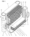
- Fig. 1 zeigt eine Explosionsdarstellung des erfindungsgemäßen Wärmetauschers;
- Fig. 2 zeigt eine Frontansicht,
- Fig. 3 zeigt eine Draufsicht;
- Fig. 4 und 5 zeigen perspektivische Ansichten eines Teils des Wärmetauschers;
- Fig. 6 zeigt eine perspektivische Gesamtansicht des Wärmetauschers;
- Fig. 7 zeigt eine Einzelheit des Flachrohres;
- Fig. 8 und 9 zeigen eine alternative Ausführung;
- Fig. 1 shows an exploded view of the heat exchanger according to the invention;
- 2 shows a front view,
- Fig. 3 is a plan view;
- Figs. 4 and 5 are perspective views of a part of the heat exchanger;
- Fig. 6 is an overall perspective view of the heat exchanger;
- Fig. 7 shows a detail of the flat tube;
- Figs. 8 and 9 show an alternative embodiment;
Sämtliche dargestellten Einzelteile des Wärmetauschers bestehen aus Metall, vorzugsweise aus Aluminium oder Aluminiumlegierungen, welches zweckmäßig mit einer Lotschicht überzogen ist. Die Einzelteile, wie Flachrohre 1, Rippen 4, Rohrböden 5, Sammelkästen 6 und Seitenteile 30 werden aus Blechen hergestellt, wodurch jedoch nicht ausgeschlossen ist, dass beispielsweise die Flachrohre 1 auch als gezogene Rohre hergestellt werden könnten. Die Flachrohre 1 haben einen etwa rechteckigen Querschnitt, wobei jedoch die Schmalseiten 2 auch etwas nach außen gewölbt sein können. Im gezeigten Ausführungsfall befinden sich Inneneinsätze in den Flachrohren 1. Die Flachrohre 1 werden dann mit den Rippen 4 gestapelt, um einen Flachrohr - Rippen - Block zu bilden. An den Enden der Flachrohre 1 werden Rohrböden 5 angesetzt, wobei sich die Enden der Flachrohre 1 in Öffnungen 21 der Rohrböden 5 befinden, wo später eine dichte Lötverbindung ausgebildet wird. Dann werden die Sammelkästen 6 aufgesetzt, und zwar, wie insbesondere die Fig. 4 erkennen lässt, werden dabei die Vorsprünge 11 an den Rändern 10 der Sammelkästen 6 in die Randbereiche der Flachrohre 1, die durch die geringfügig über die Ränder 20 des Rohrbodens 5 überstehenden Schmalseiten 2 der Flachrohre 1 gebildet sind, eingesteckt. Am Rand der Öffnungen 21 in den Rohrböden 5 befinden sich vorzugsweise Durchzüge, (nicht dargestellt) die vorzugsweise vom Sammelkasten 6 weg weisen, sodass die Flachrohrenden nicht nach innen überstehen, um für geringen Druckverlust des in die Flachrohre 1 einströmenden Mediums zu sorgen. Zwischen den Öffnungen 21 in den Rohrböden 5 sind Stege 22 vorhanden. Die Stege 22 können profiliert ausgebildet werden, um deren Steifigkeit zu erhöhen. Schließlich werden die Seitenteile 30 angesetzt, die gleichzeitig die stirnseitigen Öffnungen 60 der Sammelkästen 6 verschließen. Die Seitenteile 30 besitzen dazu an ihren Enden je ein napfartig umgeformtes Verschlussstück, das in die Öffnung 60 hinein passt. Mittels umformbarer Halteelemente 61, die in einen Schlitz 62 der Seitenteile eingreifen, werden die Seitenteile 30 vorfixiert und halten die Einzelteile des Wärmetauschers zusammen. In dieser Form ist der Wärmetauscher für die Durchführung des CAB - Hartlötprozesses im Wesentlichen vorbereitet. Sämtliche Verbindungen werden in einem Arbeitsgang im Lötofen hergestellt.All illustrated individual parts of the heat exchanger are made of metal, preferably of aluminum or aluminum alloys, which is expediently coated with a layer of solder. The items such as
Die Form der Vorsprünge 11 wird zweckmäßig an die im Bereich der Schmalseiten 2 vorhandene Kontur der Flachrohre 1 angepasst, sodass sowohl das Einführen erleichtert ist als auch dichte Lötverbindungen zur Verfügung gestellt werden. Damit werden auch gewisse Fertigungstoleranzen aufgefangen. Der Abstand der Vorsprünge 11 am Rand der Sammelkästen 6 korrespondiert mit dem Abstand der Flachrohre 1 in der Reihe bzw. mit der Höhe der zwischen den Flachrohren 1 angeordneten Rippen 4. Hier müssen gewisse Toleranzen zulässig sein, die jedoch durch die zweckmäßige Form der Vorsprünge 11 kompensiert werden können.The shape of the
Die Sammelkästen 6 sind von besonders herstellungsfreundlicher, einfacher Gestalt. Lediglich zwei Abkantungen sind notwendig, um die beiden Längswände und eine Querwand auszubilden. Beispielsweise Anschlussstutzen 70 lassen sich durch Umformverfahren leicht realisieren.The
Es sollen auch besonders herstellungsfreundliche Rohrböden 5 zum Einsatz kommen, die aus endlosem Band gefertigt und lediglich noch auf die passende Länge geschnitten werden müssen, weil diese an ihren Stirnseiten keine abgekanteten Ränder besitzen. Es werden demnach keine teuren Ziehwerkzeuge benötigt. Hier bietet sich ein Hinweis auf die Fig. 4 und 5 an. Dort ist zu sehen, dass am Rand 10 des Sammelkastens 6 ein mit den Vorsprüngen 11 vergleichbarer Ansatz 100 vorhanden ist. Dieser wirkt mit dem korrespondierenden Ausschnitt 101 am Rand 20 des Rohrbodens 5 zusammen und sorgt dort für dichte Lötverbindungen. Aus der Fig. 5 kann ferner entnommen werden, dass sich die Öffnungen 21 im Rohrboden 5 bis in den Rand 20 hinein erstrecken, was mit dem Bezugszeichen 22 kenntlich gemacht ist. Deshalb können die Rohrböden 5 bei der Montage auch quer zu ihrer Längsrichtung, bzw. in Richtung der Breitseiten 3 der Flachrohrenden, auf dieselben geschoben werden. Im Stand der Technik ist dazu eine Bewegung in Längsrichtung der Flachrohre erforderlich. Man spricht dort vom "Aufziehen" der Rohrböden.It should also be particularly production-
Insbesondere die Fig. 3 und 6 zeigen in einer Ansicht auf eines der Seitenteile 30, dass es keine seitlichen Überstände der Rohrböden 5 über den Flachrohr-Rippen Block gibt. Die Breite der Seitenteile 30 entspricht etwa dem Maß der Breitseiten 3 der Flachrohre 1. In particular, FIGS. 3 and 6 show, in a view of one of the
Es sei ferner darauf hingewiesen, dass der erfindungsgemäße Wärmetauscher einen ziemlich leichten Zugang von außen zu löttechnisch kritischen Verbindungen gestattet. Solche kritischen Verbindungen sind die Flachrohr-Rohrboden-Verbindungen. Sollten dort nach der Durchführung des Lötprozesses Undichtigkeiten vorhanden sein, so können die entsprechenden Stellen, da sie weitestgehend zugänglich sind, einfach nachbehandelt und in einem zweiten Lötdurchgang beseitigt werden. Bei Wärmetauschern aus dem Stand der Technik ist so etwas oft nicht möglich, was durch hohe Ausschussraten zum Ausdruck kommt.It should also be noted that the heat exchanger according to the invention allows a fairly easy access from the outside to soldering critical connections. Such critical connections are the flat tube tube sheet connections. If there are any leaks after the soldering process has been carried out, the corresponding points can be simply aftertreated and eliminated in a second soldering pass as they are largely accessible. In heat exchangers of the prior art, such a thing is often not possible, which is expressed by high reject rates.
Die Fig. 7 zeigt schematisch ein einzelnes Flachrohr 1, und zwar einen Blick auf das Flachrohrende. Solche Flachrohre 1 sind in dem Wärmetauscher in gewünschter Anzahl vorhanden. In jedes Flachrohr 1 erstrecken sich zwei Vorsprünge 11. Die Eindringtiefe braucht nur wenige Millimeter zu betragen, 10 - 15 mm ist schon mehr als genug. Praktisch werden es eher weniger sein. Es versteht sich, dass sich der eine Vorsprung 11 an dem einen Rand des Sammelkastens 6 befindet und der andere Vorsprung 11 an dem gegenüberliegenden anderen Rand 10 des Sammelkastens 6. Die Vorsprünge 11 liegen von innen dicht an den Schmalseiten 2 des Flachrohres 1 an. In den Flachrohren 1 befindet sich ein Inneneinsatz 80, wie es insbesondere für mit Kühlluft beaufschlagte Ladeluftkühler typisch ist. Bei anderen Einsatzfällen wird auf einen Inneneinsatz völlig verzichtet. Praktisch ist es oft schwierig, die Inneneinsätze 80 so in die Flachrohre 1 einzufügen, dass im Bereich der Schmalseiten 2 möglichst kein Bypass für die durchströmende Ladeluft entsteht, der sich nachteilig auf den Wärmeaustausch auswirkt. Wie die Fig. 7 zeigt, wirken sich die Vorsprünge 11 günstig auf die Reduzierung des schädlichen Bypasses aus, was als weiterer Vorteil der Erfindung zum Tragen kommt. Die kleinen Spalte in den Ecken des Flachrohres 1 haben ihre Ursache in der Darstellung. Praktisch sind sie nicht vorhanden oder werden sicher im Lötprozess verschlossen. Die erwähnten Spalte werden sich beim Einführen der Vorsprünge 11 auch einebnen, denn die Vorsprünge 11 halten beide Breitseiten 3 in Richtung des Pfeils unter einer gewissen Spannung.Fig. 7 shows schematically a single
Die Fig. 8 und 9 zeigen nun ein alternatives Design, bei dem die Vorsprünge 11 an den Rohrböden 5 angeordnet sind. In diesem Fall müssen die Rohrböden 5 in Rohrlängsrichtung aufgezogen werden, wobei gleichzeitig die Vorsprünge 11 in die Flachrohrenden 1 eingeführt werden. Danach werden die Sammelkästen 6 und die Seitenteile 30 angesetzt und montiert.FIGS. 8 and 9 now show an alternative design, in which the
Insgesamt stellt die Erfindung demnach ein innovatives Produkt zur Verfügung, welches, gemessen am Stand der Technik, nur wenig Wünsche offen lässt.Overall, the invention accordingly provides an innovative product which, compared to the state of the art, leaves only little to be desired.
Claims (14)
und mit in Abständen angeordneten Vorsprüngen (11),
dadurch gekennzeichnet, dass die Abstände der Vorsprünge (11) mit den Abständen der Flachrohre (1) korrespondieren, sodass die Vorsprünge (11) im Bereich der Schmalseiten (2) in die Enden der Flachrohre (1) eingreifen. 1. all-metal heat exchanger, consisting of flat tubes (1) with two narrow - and two broad sides (2, 3) and of ribs (4) which together with the flat tubes form a block, and at least one tube plate (5) and a collecting box (6), whereby edges (10) of the collecting box (6) are connected, for example soldered, to edges (20) of the tube bottom (5),
and with spaced-apart projections (11),
characterized in that the spacings of the projections (11) correspond to the spacings of the flat tubes (1), so that the projections (11) in the region of the narrow sides (2) engage in the ends of the flat tubes (1).
Priority Applications (9)
| Application Number | Priority Date | Filing Date | Title |
|---|---|---|---|
| EP05012589A EP1731864A1 (en) | 2005-06-11 | 2005-06-11 | Metallic heat exchanger and method for manufacturing the same |
| BRPI0611998-0A BRPI0611998A2 (en) | 2005-06-11 | 2006-02-18 | full metal heat exchanger and method for its production |
| DE502006000358T DE502006000358D1 (en) | 2005-06-11 | 2006-02-18 | ALL-METAL HEAT EXCHANGER AND METHOD FOR THE PRODUCTION THEREOF |
| ES06707072T ES2302323T3 (en) | 2005-06-11 | 2006-02-18 | ENTIRE METALLIC HEAT EXCHANGERS AND PROCEDURE FOR MANUFACTURING. |
| KR1020087000720A KR100957665B1 (en) | 2005-06-11 | 2006-02-18 | Fully-Metal Heat Exchanger and Method for its Production |
| EP06707072A EP1774245B1 (en) | 2005-06-11 | 2006-02-18 | Fully-metal heat exchanger and method for its production |
| PCT/EP2006/001487 WO2006133748A1 (en) | 2005-06-11 | 2006-02-18 | Fully-metal heat exchanger and method for its production |
| CNA2006800207763A CN101194140A (en) | 2005-06-11 | 2006-02-18 | Metallic heat exchanger and method for manufacturing the same |
| US11/916,459 US20080230213A1 (en) | 2005-06-11 | 2006-02-18 | Fully-Metal Heat Exchanger And Method For Its Production |
Applications Claiming Priority (1)
| Application Number | Priority Date | Filing Date | Title |
|---|---|---|---|
| EP05012589A EP1731864A1 (en) | 2005-06-11 | 2005-06-11 | Metallic heat exchanger and method for manufacturing the same |
Publications (1)
| Publication Number | Publication Date |
|---|---|
| EP1731864A1 true EP1731864A1 (en) | 2006-12-13 |
Family
ID=35124736
Family Applications (1)
| Application Number | Title | Priority Date | Filing Date |
|---|---|---|---|
| EP05012589A Withdrawn EP1731864A1 (en) | 2005-06-11 | 2005-06-11 | Metallic heat exchanger and method for manufacturing the same |
Country Status (2)
| Country | Link |
|---|---|
| EP (1) | EP1731864A1 (en) |
| CN (1) | CN101194140A (en) |
Cited By (3)
| Publication number | Priority date | Publication date | Assignee | Title |
|---|---|---|---|---|
| CN103105091A (en) * | 2013-02-20 | 2013-05-15 | 安徽天祥空调科技有限公司 | Sideboard for whole brazing full-aluminum module radiator |
| CN109405302A (en) * | 2018-11-30 | 2019-03-01 | 浙江华地电子有限公司 | A kind of stainless heat exchanger water box |
| DE102021213357A1 (en) | 2021-11-26 | 2023-06-01 | Robert Bosch Gesellschaft mit beschränkter Haftung | Cooling device for cooling electronic components |
Families Citing this family (5)
| Publication number | Priority date | Publication date | Assignee | Title |
|---|---|---|---|---|
| US9309839B2 (en) | 2010-03-18 | 2016-04-12 | Modine Manufacturing Company | Heat exchanger and method of manufacturing the same |
| AU2011201083B2 (en) | 2010-03-18 | 2013-12-05 | Modine Manufacturing Company | Heat exchanger and method of manufacturing the same |
| CN102996230A (en) * | 2012-11-19 | 2013-03-27 | 泰安鼎鑫冷却器有限公司 | Cooling tube reinforcing card applied to intercooler |
| CN106802099B (en) * | 2015-11-25 | 2020-09-29 | 浙江三花汽车零部件有限公司 | Heat exchanger |
| CN110514029A (en) * | 2019-09-02 | 2019-11-29 | 枣庄学院 | A kind of charger-air cooler |
Citations (5)
| Publication number | Priority date | Publication date | Assignee | Title |
|---|---|---|---|---|
| EP0656517A1 (en) * | 1993-12-03 | 1995-06-07 | THERMAL-WERKE Wärme-, Kälte-, Klimatechnik GmbH | Water-air heat exchanger of aluminium for motor vehicles |
| EP0704666A1 (en) * | 1994-09-29 | 1996-04-03 | Zexel Corporation | Heat exchanger |
| DE19819247A1 (en) * | 1998-04-29 | 1999-11-11 | Valeo Klimatech Gmbh & Co Kg | Vehicle heat exchanger and especially water/air heat exchanger or evaporator |
| DE19942458A1 (en) * | 1998-09-29 | 2000-03-30 | Denso Corp | Heat exchanger for air conditioning system in vehicle has slim profile with water inlet and outlet at opposite ends of top tank and with profiled inner wall to separate inlet and outlet sections |
| DE10244629A1 (en) * | 2001-09-27 | 2003-04-10 | Denso Corp | Heat exchanger used as a heating core in a vehicle air-conditioning unit comprises tubes containing fluid connected to a container having a graduated design with a first step region |
-
2005
- 2005-06-11 EP EP05012589A patent/EP1731864A1/en not_active Withdrawn
-
2006
- 2006-02-18 CN CNA2006800207763A patent/CN101194140A/en active Pending
Patent Citations (5)
| Publication number | Priority date | Publication date | Assignee | Title |
|---|---|---|---|---|
| EP0656517A1 (en) * | 1993-12-03 | 1995-06-07 | THERMAL-WERKE Wärme-, Kälte-, Klimatechnik GmbH | Water-air heat exchanger of aluminium for motor vehicles |
| EP0704666A1 (en) * | 1994-09-29 | 1996-04-03 | Zexel Corporation | Heat exchanger |
| DE19819247A1 (en) * | 1998-04-29 | 1999-11-11 | Valeo Klimatech Gmbh & Co Kg | Vehicle heat exchanger and especially water/air heat exchanger or evaporator |
| DE19942458A1 (en) * | 1998-09-29 | 2000-03-30 | Denso Corp | Heat exchanger for air conditioning system in vehicle has slim profile with water inlet and outlet at opposite ends of top tank and with profiled inner wall to separate inlet and outlet sections |
| DE10244629A1 (en) * | 2001-09-27 | 2003-04-10 | Denso Corp | Heat exchanger used as a heating core in a vehicle air-conditioning unit comprises tubes containing fluid connected to a container having a graduated design with a first step region |
Cited By (3)
| Publication number | Priority date | Publication date | Assignee | Title |
|---|---|---|---|---|
| CN103105091A (en) * | 2013-02-20 | 2013-05-15 | 安徽天祥空调科技有限公司 | Sideboard for whole brazing full-aluminum module radiator |
| CN109405302A (en) * | 2018-11-30 | 2019-03-01 | 浙江华地电子有限公司 | A kind of stainless heat exchanger water box |
| DE102021213357A1 (en) | 2021-11-26 | 2023-06-01 | Robert Bosch Gesellschaft mit beschränkter Haftung | Cooling device for cooling electronic components |
Also Published As
| Publication number | Publication date |
|---|---|
| CN101194140A (en) | 2008-06-04 |
Similar Documents
| Publication | Publication Date | Title |
|---|---|---|
| EP1774245B1 (en) | Fully-metal heat exchanger and method for its production | |
| EP0519334B1 (en) | Flat tube heat exchanger, process for manufacturing same, applications and flat tubes for heat exchanger | |
| EP1710526B1 (en) | Heat exchanger, in particular intercooler | |
| EP1281923B1 (en) | Flat tube for heat exchanger and process of fabricating the same | |
| EP0656517B1 (en) | Water-air heat exchanger of aluminium for motor vehicles | |
| EP0864838B1 (en) | Heat exchanger for automotive vehicle | |
| EP1701125A2 (en) | Heat exchanger with flat tubes and flat tube for heat exchanger | |
| DE102014005149B4 (en) | Brazed heat exchanger | |
| EP2021717B1 (en) | Heat exchanger for motor vehicles | |
| EP1731864A1 (en) | Metallic heat exchanger and method for manufacturing the same | |
| DE4305060C2 (en) | Soldered heat exchanger, especially evaporator | |
| DE10315371A1 (en) | Heat exchanger | |
| DE19722098B4 (en) | Heat exchanger for a motor vehicle | |
| EP1657512B1 (en) | Heat exchanger with open profile as housing | |
| EP1376043B1 (en) | Heat exchanger with diffuser | |
| DE3834822A1 (en) | Heat exchanger | |
| DE102017214822A1 (en) | HEAT EXCHANGERS | |
| EP1500892A2 (en) | Heat exchanger for vehicles | |
| EP1567819A1 (en) | Heat exchanger unit, in particular for a motor vehicle and method for producing said unit | |
| DE102009012509A1 (en) | Heat exchanger e.g. charge air cooler, for internal combustion engine, has tubular plate comprising four edge sides in which one of edge sides is flexible and establishes operative connection with end portion of side part at rear side | |
| EP1148312B1 (en) | Radiator for vehicles | |
| EP1771697B1 (en) | Heat exchanger, box for receiving a fluid for a heat exchanger, and method for the production of such a box | |
| DE102010040983A1 (en) | Gas cooler e.g. indirect intercooler, for motor car, has locking element connected with end edge of housing portions and completely penetrating through pipe base in region of outer pipe in direction of pipes | |
| EP1764570A1 (en) | All-metal heat exchanger | |
| DE102008036614A1 (en) | heat exchangers |
Legal Events
| Date | Code | Title | Description |
|---|---|---|---|
| PUAI | Public reference made under article 153(3) epc to a published international application that has entered the european phase |
Free format text: ORIGINAL CODE: 0009012 |
|
| AK | Designated contracting states |
Kind code of ref document: A1 Designated state(s): AT BE BG CH CY CZ DE DK EE ES FI FR GB GR HU IE IS IT LI LT LU MC NL PL PT RO SE SI SK TR |
|
| AX | Request for extension of the european patent |
Extension state: AL BA HR LV MK YU |
|
| STAA | Information on the status of an ep patent application or granted ep patent |
Free format text: STATUS: THE APPLICATION HAS BEEN WITHDRAWN |
|
| 17P | Request for examination filed |
Effective date: 20070613 |
|
| 18W | Application withdrawn |
Effective date: 20070622 |