EP1731636A2 - Support for a twin pressure roller of a drafting frame - Google Patents
Support for a twin pressure roller of a drafting frame Download PDFInfo
- Publication number
- EP1731636A2 EP1731636A2 EP06006651A EP06006651A EP1731636A2 EP 1731636 A2 EP1731636 A2 EP 1731636A2 EP 06006651 A EP06006651 A EP 06006651A EP 06006651 A EP06006651 A EP 06006651A EP 1731636 A2 EP1731636 A2 EP 1731636A2
- Authority
- EP
- European Patent Office
- Prior art keywords
- pressure roller
- twin
- roller
- rollers
- axis
- Prior art date
- Legal status (The legal status is an assumption and is not a legal conclusion. Google has not performed a legal analysis and makes no representation as to the accuracy of the status listed.)
- Withdrawn
Links
Images

Classifications
-
- D—TEXTILES; PAPER
- D01—NATURAL OR MAN-MADE THREADS OR FIBRES; SPINNING
- D01H—SPINNING OR TWISTING
- D01H5/00—Drafting machines or arrangements ; Threading of roving into drafting machine
- D01H5/18—Drafting machines or arrangements without fallers or like pinned bars
- D01H5/56—Supports for drafting elements
- D01H5/565—Top roller arms
Definitions
- the invention relates to a holder for a fixed axis and two rotatably mounted upper rollers having Druckwalzenzwilling a multiple lower rollers having drafting with at least one axis of Druckwalzenzwillings associated positioning element and at least one force application element, wherein the positioning element is arranged in the region of the center of the axis of Druckwalzenzwillings and the pressure roller twin allows oscillation about the center, and wherein the holder with the pressure roller twin of the lower rollers is lifted.
- the printing roll twin is held in the center of its axis by a positioning element and positioned with respect to the associated lower roller.
- the positioning element is adjustable in the fiber transport direction and allows the setting of a so-called curtain or rear of the top rollers.
- the axes of rotation of the upper rollers with respect to the fiber transport direction are arranged offset slightly to the rotational axes of the lower roller forward or backward.
- the axis of Druckwalzenzwillings is included in the positioning element, that a commuting around the center is made possible.
- the introduction of force of a pressing force for the load of the top rollers is integrated in the positioning element in the middle of the axis of the pressure roller twin.
- the known holder has proven very well in practice at drafting systems with relatively small pitch, for example in drafting systems for ring spinning machines. After lifting the Druckwalzenzwillings from the lower rollers, which may be necessary, for example, for troubleshooting, find the top rollers when placed on the lower rollers automatically back to their position of the set front or rear, and the pressure roller twin is directed by the pendulum back to exactly the lower roller.
- the holder with the positioning element need not be aligned parallel to the lower rollers. This is a decisive advantage, since usually a large number of components is used for fastening and loading of the holder with the pressing force, in which a good parallelism of Positions mecanices with the lower rollers can not be guaranteed by the addition of individual tolerances.
- the invention is based on the object to improve the known holder and to allow even in drafting systems with large pitches a pendulum option of Druckwalzenzwillings without incorrect positioning of the upper rollers is possible when placing the Druckwalzenzwillings.
- the object is achieved in that at least one backup bearing for coarse positioning when placed on the lower rollers is assigned to the printing roll at least.
- the pendulum option of Druckwalzenzwillings can be adjusted so that when placing the Druckwalzenzwillings a mispositioning of the two upper rollers is excluded and that nevertheless can take place during application of the pressing force parallel alignment of Druckwalzenzwillings to the lower rollers.
- the fishing camps act at least shortly before the placement of the pressure roller twin and advantageously provide a rough parallel alignment of the pressure roller twin to an extent that the top rollers of the pressure roller twin, depending on the selected setting either sit with curtain or both with the back of the lower rollers.
- the provided within the coarse parallel alignment pendulum option then allows the pressure roll twin then when applying the pressing force to be able to align exactly parallel to the lower rollers. An attachment of a top roller with curtain and the other top roller with the back is effectively prevented.
- the fishing camp can be designed in different ways.
- it acts as far as possible from the center of the axis on the twin pressure roll.
- the backup bearing should limit the pendulum movement of the pressure roller twin so far that a false placement of the top rollers is prevented, on the other hand, however, a sufficiently large pendulum must remain that under the action of the pressing force exact parallel alignment of Druckwalzenzwillings is possible.
- the safety bearing is thus designed so that it leads to the pressure roller twin until it touches the lower rollers, then but does not hinder the twin-roll twin in its pendulum alignment parallel to the lower rolls.
- the backup bearing can be assigned to a top roller of the pressure roller twin, but it has a particularly advantageous effect on the axis of the pressure roller twin, since it does not start to rotate even when placed on it.
- an advantageous embodiment of the invention is provided when two fishing camps are spaced apart and arranged in the vicinity of the top rollers. It is characterized in a simple manner a symmetrical configuration of the components, in particular the holder, possible. It is also advantageous that the force introduction element, which initiates the pressing force for the top rollers in the axis of the pressure roller twin, is integrated in the positioning element. Thus, the force is introduced together with the positioning in the middle of the axis of the pressure roller twin and the force is divided by itself evenly on both top rollers.
- the safety bearing is advantageously designed like a fork and prevents even when lifting the Druckwalzenzwillings from the lower roller that the pressure roller twin comes too much out of position.
- the drafting system 1 partially shown in Figure 1 includes a plurality of roller pairs 2, 3 and 4, 5, which transport a fiber strand 6 in the fiber transport direction A through the drafting system 1 and thereby forgiven to the desired fineness.
- the roller pair 4, 5 are assigned in a conventional manner guide straps 7 and 8. It can be provided that the drafting arrangement 1 contains further roller pairs, not shown, which precede the roller pair 4, 5 or follow the roller pair 2, 3.
- the distorted to its desired fineness fiber structure 6 is subsequently fed to the drafting a per se arbitrary twist distribution member, such as an air jet unit, where the fiber strand 6 of the spinning twist is issued.
- the upper rollers 3 and 5 are positioned and pressed by brackets 9 with respect to the drivable lower rollers 2 and 4.
- the top rollers 3 and 5 are not driven themselves, but are entrained by the movement of the lower rollers 2, 4.
- the holder 9 is acted upon in any known and known manner by load means, not shown, with a pressing force F and can be lifted with the upper roller 3 or 5 of the lower roller 2 and 4 respectively.
- the pressing force F can be applied both by pneumatic or magnetic force generating elements and by metallic springs.
- the upper rollers 3 of two adjacent spinning stations are combined with a common axle 10 to form a twin-roller 11.
- the two lower rollers 2 of these adjacent spinning stations can be designed as a single bottom rollers with separate drives. But you can as well as in Machine longitudinal direction continuous sub-cylinder be configured in the manner shown in dashed lines.
- the top rollers 3, 5 are arranged with respect to the respective bottom roller 2, 4 with a light curtain or rear.
- the arrangement of the upper roller 5 is referred to the lower roller 4, in which the upper roller 5 seen in the fiber transport direction A slightly further upstream than the lower roller 4 is arranged.
- the roller pair 2, 3 shows a curtain of the upper roller 3, in which the upper roller is arranged in the fiber transport direction A downstream of the lower roller 2.
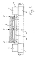
- Figure 2 shows a plan view of the pair of rollers 2, 3, wherein the holder 9 is cut along the sectional surface II-II of Figure 1.
- a positioning element 13 contained in the holder 9 is provided in the area of the center 12 of the axis 10 of the pressure roller twin 11.
- the positioning element 13 has positioning surfaces 14 which cooperate with the axis 10 and ensure the positioning of the pressure roller twin 11 with the desired curtain with respect to the lower rollers 2.
- the positioning surfaces 14 in this case have a clearance fit with the axis 10, so that the pressure roller twin 11 can perform in the direction of arrow B and C about the center 12 a pendulum motion.
- the pendulum option in the direction of arrow B and C in conjunction with the set front or rear causes an automatic alignment of Druckwalzenzwillings parallel to the lower rollers 2.
- a caused by an inclination of the upper roller 3 to the lower roller 2 uneven clamping of the fiber structure 6 with resulting uneven Delay is prevented.
- the positioning surface 14 can also be performed slightly spherical.
- the pendulum motion of the pressure roller twin 11 is so large that it is at a touchdown of the pressure roller twin 11, after this was lifted to eliminate a malfunction of the lower rollers 2 to an incorrect positioning of the pressure roller twin 11 comes.
- the axis 10 of the pressure roller twin is tilted so far that the one top roller 3 touches a curtain and the other top roller 3 with a rear surface on the respective bottom roller 2. In such a state, spinning is not possible.
- the pressure roller twin 11 to allocate at least one fishing camp 15, which when placing the Druckwalzenzwillings 11 on the lower rollers 2 for coarse positioning of the pressure roller twin 11 is used and prevents erroneous placement.
- the fishing camp 15 can be assigned to the axis 10 of the pressure rolling twin 11.
- the fishing camp 15 has at least one catching surface 16, which restricts the pressure roller twin 11 in its pendulum motion in the direction B or C, as soon as the pendulum angle exceeds a certain size.
- the fishing camp 15 is advantageously arranged as far as possible from the center 12 of the pressure rolling twin 11.
- the catching surfaces 16 are arranged at such a distance from the axis 10 of the pressure roller twin that they prevent erroneous placement of Druckwalzenzwillings on the lower rollers, but do not hinder the pendulum motion for parallel alignment of Druckwalzenzwillings. This objective is the more easily achievable, the farther the fishing camp 15 are away from the center 12.
- the pressing force F must be introduced through the holder 9 into the axis 10 of the pressure roller twin. This can be done by integrating a force introduction element into the positioning element 13. In this embodiment, not shown, the pressing force F is distributed by the axis 10 on the two top rollers 3 of the pressure roller twin 11. In the drafting system shown here with a large pitch E and compared to relatively small diameter D of the axis 10 of the pressure rolling twin 11, depending on the size of the pressing force F, the deflection of the axis 10 can become so large that a misalignment of the top rollers 3 occurs due to the deformation , which in turn affects the uniformity of the distorted fiber structure.
- the diameter D of the axis 10 is often less than one-tenth of the pitch E.
- force introduction elements 17, as shown in FIG. 3, separately from the positioning element 13.
- the force introduction element is arranged as close as possible to the top roller 3 and transmits the pressing force F from the holder 9 by pressure surfaces 18 on the axis 10.
- the pressure surfaces 18 are advantageously formed as flat surfaces, which transmit the pressing force F on the axis 10, without affecting the position of the axis 10 and without forcing the pressure roller twin in a possibly wrong position.
- the fishing camp 15 is integrated in the force introduction element 17.
- the integrated component can advantageously be designed like a fork, in which the fork base the pressure surfaces 18 and the side surfaces of the fork contain the catching surfaces 16.
- the upper roller 5 with the ceremoniessriemchen 8 can of course just like the previously described upper roller 3 may be formed as Druckwalzenzwilling 11, which is positioned in the same way by a holder 9 and loaded with a pressing force F.
Landscapes
- Engineering & Computer Science (AREA)
- Mechanical Engineering (AREA)
- Textile Engineering (AREA)
- Spinning Or Twisting Of Yarns (AREA)
- Inking, Control Or Cleaning Of Printing Machines (AREA)
Abstract
Description
Die Erfindung betrifft eine Halterung für einen eine feststehende Achse und zwei drehbar gelagerte Oberwalzen aufweisenden Druckwalzenzwilling eines mehrere Unterwalzen aufweisenden Streckwerkes mit wenigstens einem der Achse des Druckwalzenzwillings zugeordneten Positionierungselement und wenigstens einem Krafteinleitungselement, wobei das Positionierungselement im Bereich der Mitte der Achse des Druckwalzenzwillings angeordnet ist und dem Druckwalzenzwilling ein Pendeln um die Mitte ermöglicht, und wobei die Halterung mit dem Druckwalzenzwilling von den Unterwalzen abhebbar ist.The invention relates to a holder for a fixed axis and two rotatably mounted upper rollers having Druckwalzenzwilling a multiple lower rollers having drafting with at least one axis of Druckwalzenzwillings associated positioning element and at least one force application element, wherein the positioning element is arranged in the region of the center of the axis of Druckwalzenzwillings and the pressure roller twin allows oscillation about the center, and wherein the holder with the pressure roller twin of the lower rollers is lifted.
Aus der
Eine exakt parallele Ausrichtung des Druckwalzenzwillings zu den Unterwalzen ist wichtig, damit der Verzug des Faserverbandes gleichmäßig stattfinden kann. Wenn eine Oberwalze zu der ihr zugeordneten Unterwalze nicht parallel ist, dann ist die Klemmung des Faserverbandes über die Walzenbreite unterschiedlich und der Faserverband wird ungleichmäßig verzogen.An exactly parallel alignment of the pressure roller twin to the lower rollers is important so that the distortion of the fiber structure can take place evenly. If a top roll is not parallel to its associated bottom roll, then the clamping of the fiber strand over the roll width will be different and the fiber strand will be distorted unevenly.
Die Krafteinleitung einer Andrückkraft für die Belastung der Oberwalzen erfolgt integriert im Positionierungselement in der Mitte der Achse des Druckwalzenzwillings.The introduction of force of a pressing force for the load of the top rollers is integrated in the positioning element in the middle of the axis of the pressure roller twin.
Die bekannte Halterung hat sich in der Praxis bei Streckwerken mit relativ kleiner Teilung, beispielsweise bei Streckwerken für Ringspinnmaschinen, sehr gut bewährt. Nach einem Abheben des Druckwalzenzwillings von den Unterwalzen, welches beispielsweise zum Zwecke der Störungsbehebung notwendig sein kann, finden die Oberwalzen beim Aufsetzen auf die Unterwalzen wieder automatisch in ihre Position des eingestellten Vor- oder Rückhangs, und der Druckwalzenzwilling richtet sich durch die Pendelmöglichkeit wieder exakt zu der Unterwalze aus. Die Halterung mit dem Positionierungselement braucht nicht parallel zu den Unterwalzen ausgerichtet werden. Dies ist ein entscheidender Vorteil, da zur Befestigung und Belastung der Halterung mit der Andrückkraft üblicherweise eine große Anzahl von Bauteilen eingesetzt wird, bei denen durch die Addition der Einzeltoleranzen eine gute Parallelität des Positionierungslementes mit den Unterwalzen nicht gewährleistet werden kann.The known holder has proven very well in practice at drafting systems with relatively small pitch, for example in drafting systems for ring spinning machines. After lifting the Druckwalzenzwillings from the lower rollers, which may be necessary, for example, for troubleshooting, find the top rollers when placed on the lower rollers automatically back to their position of the set front or rear, and the pressure roller twin is directed by the pendulum back to exactly the lower roller. The holder with the positioning element need not be aligned parallel to the lower rollers. This is a decisive advantage, since usually a large number of components is used for fastening and loading of the holder with the pressing force, in which a good parallelism of Positionsierungslementes with the lower rollers can not be guaranteed by the addition of individual tolerances.
Bei größer werdender Teilung von über 100 mm kann es jedoch sehr leicht vorkommen, dass schon ein kleiner Pendelwinkel zu einem so großen Versatz der einen Oberwalze des Druckwalzenzwillings zu der anderen Oberwalze kommt, so dass die eine Oberwalze mit Vorhang und die andere Oberwalze des Druckwalzenzwillings mit Rückhang zur Unterwalze aufsetzt. Insbesondere bei Streckwerken für Luftspinnmaschinen, die eine große Teilung von 200 mm und mehr aufweisen können, sind solche bekannten Halterungen nicht mehr betriebssicher verwendbar. Beim Aufsetzen des Druckwalzenzwillings nach einem Abhebevorgang finden die Oberwalzen nicht von selbst in ihre Soll-Position, da der Pendelwinkel durch das Positionierungselement nicht so eingeschränkt werden kann, dass ein Aufsetzen der einen Oberwalze mit Vorhang und der anderen Oberwalze mit Rückhang dauerhaft verhindert werden kann.With increasing pitch of about 100 mm, however, it can happen very easily that even a small pendulum angle comes to such a large offset of a top roll of the pressure roller twin to the other top roll, so that the one top roll with curtain and the other top roll of Druckwalzenzwillings with Rear of the lower roller touches down. In particular, in drafting for air spinning machines, which may have a large pitch of 200 mm and more, such known brackets are no longer safe to use. When placing the Druckwalzenzwillings after a lift off the top rollers do not find themselves in their desired position, since the pendulum angle can not be limited by the positioning element so that a placement of a top roller with curtain and the other top roller with rear can be permanently prevented.
Aus der
Der Erfindung liegt die Aufgabe zu Grunde, die bekannte Halterung zu verbessern und auch bei Streckwerken mit großen Teilungen eine Pendelmöglichkeit des Druckwalzenzwillings zu ermöglichen, ohne das beim Aufsetzen des Druckwalzenzwillings eine Fehlpositionierung der Oberwalzen möglich ist.The invention is based on the object to improve the known holder and to allow even in drafting systems with large pitches a pendulum option of Druckwalzenzwillings without incorrect positioning of the upper rollers is possible when placing the Druckwalzenzwillings.
Die Aufgabe wird dadurch gelöst, dass dem Druckwalzenzwilling wenigstens ein Fanglager zur Grobpositionierung beim Aufsetzen auf die Unterwalzen zugeordnet ist.The object is achieved in that at least one backup bearing for coarse positioning when placed on the lower rollers is assigned to the printing roll at least.
Durch das Vorsehen von wenigstens einem Fanglager kann die Pendelmöglichkeit des Druckwalzenzwillings auch auf Dauer so eingestellt werden, dass beim Aufsetzen des Druckwalzenzwillings eine Fehlpositionierung der beiden Oberwalzen ausgeschlossen wird und dass trotzdem beim Aufbringen der Andrückkraft eine Parallelausrichtung des Druckwalzenzwillings zu den Unterwalzen stattfinden kann. Die Fanglager wirken dabei wenigstens kurz vor dem Aufsetzen des Druckwalzenzwillings und stellen vorteilhafterweise eine grobe Parallelausrichtung des Druckwalzenzwillings in einem Maße sicher, dass die Oberwalzen des Druckwalzenzwillings je nach gewählter Einstellung entweder beide mit Vorhang oder beide mit Rückhang auf die Unterwalzen aufsetzen. Die innerhalb der groben Parallelausrichtung vorgesehene Pendelmöglichkeit ermöglicht dem Druckwalzenzwilling dann beim Aufbringen der Andrückkraft, sich exakt parallel zu den Unterwalzen ausrichten zu können. Ein Aufsetzen einer Oberwalze mit Vorhang und der anderen Oberwalze mit Rückhang wird so wirksam verhindert.By providing at least one fishing camp, the pendulum option of Druckwalzenzwillings can be adjusted so that when placing the Druckwalzenzwillings a mispositioning of the two upper rollers is excluded and that nevertheless can take place during application of the pressing force parallel alignment of Druckwalzenzwillings to the lower rollers. The fishing camps act at least shortly before the placement of the pressure roller twin and advantageously provide a rough parallel alignment of the pressure roller twin to an extent that the top rollers of the pressure roller twin, depending on the selected setting either sit with curtain or both with the back of the lower rollers. The provided within the coarse parallel alignment pendulum option then allows the pressure roll twin then when applying the pressing force to be able to align exactly parallel to the lower rollers. An attachment of a top roller with curtain and the other top roller with the back is effectively prevented.
Das Fanglager kann auf unterschiedlicher Art und Weise ausgebildet sein. Vorteilhafterweise wirkt es in möglichst großen Abstand von der Mitte der Achse auf den Druckwalzenzwilling ein. Je weiter von der Mitte der Achse des Druckwalzenzwillings, die den Drehpunkt bei der Pendelbewegung darstellt, das Fanglager angeordnet ist, desto leichter gelingt die Sicherstellung seiner etwas widersprüchlichen Funktionen. Auf der einen Seite soll das Fanglager ja die Pendelbewegung des Druckwalzenzwillings soweit einschränken, dass ein Falschaufsetzen der Oberwalzen verhindert wird, auf der anderen Seite jedoch muss eine genügend große Pendelmöglichkeit verbleiben, dass unter Einwirkung der Andrückkraft eine exakte Parallelausrichtung des Druckwalzenzwillings ermöglicht ist. Das Fanglager ist also so ausgebildet, dass es den Druckwalzenzwilling bis zum Aufsetzen auf die Unterwalzen führt, dann aber den Druckwalzenzwilling bei seiner pendelnden Ausrichtung parallel zu den Unterwalzen nicht behindert.The fishing camp can be designed in different ways. Advantageously, it acts as far as possible from the center of the axis on the twin pressure roll. The farther from the center of the axis of the pressure roll twin, which is the pivot point in the pendulum motion, the catcher is located, the easier it is to ensure its somewhat contradictory functions. On the one hand, the backup bearing should limit the pendulum movement of the pressure roller twin so far that a false placement of the top rollers is prevented, on the other hand, however, a sufficiently large pendulum must remain that under the action of the pressing force exact parallel alignment of Druckwalzenzwillings is possible. The safety bearing is thus designed so that it leads to the pressure roller twin until it touches the lower rollers, then but does not hinder the twin-roll twin in its pendulum alignment parallel to the lower rolls.
Das Fanglager kann einer Oberwalze des Druckwalzenzwillings zugeordnet sein, besonders vorteilhaft wirkt es jedoch auf die Achse des Druckwalzenzwillings, da diese auch beim Aufsetzen nicht zu rotieren beginnt. In vorteilhafter Ausgestaltung der Erfindung ist vorgesehen, wenn zwei Fanglager voneinander beabstandet und in der Nähe der Oberwalzen angeordnet sind. Es ist dadurch in einfacher Weise eine symmetrische Ausgestaltung der Bauteile, insbesondere der Halterung, möglich. Es ist weiterhin vorteilhaft, dass das Krafteinleitungselement, welches die Andrückkraft für die Oberwalzen in die Achse des Druckwalzenzwillings einleitet, in das Positionierungselement integriert ist. So erfolgt die Krafteinleitung zusammen mit der Positionierung in der Mitte der Achse des Druckwalzenzwillings und die Kraft teilt sich von selbst gleichmäßig auf beiden Oberwalzen auf.The backup bearing can be assigned to a top roller of the pressure roller twin, but it has a particularly advantageous effect on the axis of the pressure roller twin, since it does not start to rotate even when placed on it. In an advantageous embodiment of the invention is provided when two fishing camps are spaced apart and arranged in the vicinity of the top rollers. It is characterized in a simple manner a symmetrical configuration of the components, in particular the holder, possible. It is also advantageous that the force introduction element, which initiates the pressing force for the top rollers in the axis of the pressure roller twin, is integrated in the positioning element. Thus, the force is introduced together with the positioning in the middle of the axis of the pressure roller twin and the force is divided by itself evenly on both top rollers.
Je nach benötigter Andrückkraft im Verhältnis zu dem gewählten Durchmesser der Achse des Druckwalzenzwillings kann bei Anordnung des Krafteinleitungselementes in der Mitte der Achse eine sehr große Durchbiegung der Achse auftreten. Diese Durchbiegung führt zu einer Schrägstellung der beiden Oberwalzen und einer Abweichung von der parallelen Lage. Zur Vermeidung einer zu großen Durchbiegung der Achse ist es vorteilhaft, das Krafteinleitungselement getrennt vom Positionierungselement anzuordnen. Besonders vorteilhaft ist die Anordnung von wenigstens zwei Krafteinleitungselementen jeweils in der Nähe der Oberwalzen. Hierbei ist jedoch darauf zu achten, dass durch die Krafteinleitungselemente keine Zwangspositionierung erfolgt, die die pendelnde Ausrichtung des Druckwalzenzwillings behindern würde.Depending on the required pressing force in relation to the selected diameter of the axis of Druckwalzenzwillings can occur when the force application element in the middle of the axis a very large deflection of the axis. This deflection leads to an inclination of the two top rollers and a deviation from the parallel position. To avoid excessive deflection of the axis, it is advantageous to arrange the force introduction element separately from the positioning element. Particularly advantageous is the arrangement of at least two force introduction elements in each case in the vicinity of the top rollers. In this case, however, care must be taken that no force positioning takes place by the force introduction elements, which would hinder the oscillating alignment of the pressure roller twin.
Bei vom Positionierungselement getrennt angeordneten Krafteinleitungselement kann es vorteilhaft sein, das Fanglager in dem Krafteinleitungselement zu integrieren, um so beide in der Nähe der Oberwalzen auf die Achse des Druckwalzenzwillings einwirken zu lassen.When arranged separately from the positioning element force introduction element, it may be advantageous to integrate the fishing camp in the force introduction element so as to let both act in the vicinity of the top rollers on the axis of Druckwalzenzwillings.
Das Fanglager ist vorteilhafterweise gabelartig ausgeführt und verhindert schon beim Abheben des Druckwalzenzwillings von der Unterwalze, dass der Druckwalzenzwilling zu sehr aus seiner Position kommt.The safety bearing is advantageously designed like a fork and prevents even when lifting the Druckwalzenzwillings from the lower roller that the pressure roller twin comes too much out of position.
Weitere Vorteile und Merkmale der Erfindung ergeben sich aus der nachfolgenden Beschreibung einiger Ausführungsbeispiele.Further advantages and features of the invention will become apparent from the following description of some embodiments.
Es zeigen:
- Figur 1 eine teilweise geschnittene Seitenansicht auf ein nur teilweise dargestelltes Streckwerk mit Halterungen für Druckwalzenzwillinge,
Figur 2 eine entlang der Schnittfläche II-II der Figur 1 geschnittener Ansicht einer Halterung für einen Druckwalzenzwilling,Figur 3 eine entlang der Schnittfläche III-III der Figur 1 geschnittene Ansicht einer Halterung für einen Druckwalzenzwilling.
- 1 is a partially sectioned side view of an only partially illustrated drafting with brackets for Druckwalzenzwillinge,
- FIG. 2 shows a view cut along the sectional surface II-II of FIG. 1 of a holder for a printing roll twin, FIG.
- FIG. 3 shows a view cut along the sectional surface III-III of FIG. 1 of a holder for a printing roll twin.
Das in Figur 1 teilweise dargestellte Streckwerk 1 enthält mehrere Walzenpaare 2, 3 und 4, 5, die einen Faserverband 6 in Fasertransportrichtung A durch das Streckwerk 1 transportieren und dabei auf die gewünschte Feinheit verziehen. Dem Walzenpaar 4, 5 sind in an sich bekannter Weise Führungsriemchen 7 und 8 zugeordnet. Es kann vorgesehen sein, dass das Streckwerk 1 weitere nicht dargestellte Walzenpaare enthält, die dem Walzenpaar 4, 5 vorausgehen oder dem Walzenpaar 2, 3 nachfolgen. Der auf seine gewünschte Feinheit verzogene Faserverband 6 wird nachfolgend an das Streckwerk einem an sich beliebigen Drallerteilungsorgan, beispielsweise einem Luftdüsenaggregat zugeführt, wo dem Faserverband 6 der Spinndrall erteilt wird. Die Oberwalzen 3 und 5 werden durch Halterungen 9 in Bezug auf die antreibbaren Unterwalzen 2 und 4 positioniert und angedrückt. Die Oberwalzen 3 und 5 sind dabei selbst nicht angetrieben, sondem werden durch die Bewegung der Unterwalzen 2, 4 mitgenommen.The drafting system 1 partially shown in Figure 1 includes a plurality of
Die Halterung 9 wird in an sich beliebiger und bekannter Weise durch nicht dargestellte Belastungseinrichtungen mit einer Andrückkraft F beaufschlagt und ist mit der Oberwalze 3 bzw. 5 von der Unterwalze 2 bzw. 4 abhebbar. Die Andrückkraft F kann dabei sowohl durch pneumatische oder magnetische Krafterzeugungselemente als auch durch metallische Federn aufgebracht werden.The holder 9 is acted upon in any known and known manner by load means, not shown, with a pressing force F and can be lifted with the
Wie in Figur 3 zu erkennen, sind die Oberwalzen 3 von zwei benachbarten Spinnstellen mit einer gemeinsamen Achse 10 zu einem Druckwalzenzwilling 11 zusammengefasst. Die beiden Unterwalzen 2 dieser benachbarten Spinnstellen können dabei als Einzelunterwalzen mit separaten Antrieben ausgebildet sein. Sie können aber auch genauso gut als in Maschinenlängsrichtung durchlaufende Unterzylinder in der gestrichelt dargestellten Weise ausgestaltet sein.As can be seen in FIG. 3, the
Gemäß Figur 1 sind die Oberwalzen 3, 5 in Bezug auf die jeweilige Unterwalze 2, 4 mit einem leichten Vorhang oder Rückhang angeordnet. Als Rückhang wird dabei die Anordnung der Oberwalze 5 zu der Unterwalze 4 bezeichnet, bei der die Oberwalze 5 in Fasertransportrichtung A gesehen etwas weiter stromaufwärts als die Unterwalze 4 angeordnet ist. Das Walzenpaar 2, 3 zeigt einen Vorhang der Oberwalze 3, bei dem die Oberwalze in Fasertransportrichtung A stromabwärts von der Unterwalze 2 angeordnet ist.According to Figure 1, the
Figur 2 zeigt eine Draufsicht auf das Walzenpaar 2, 3, wobei die Halterung 9 entlang der Schnittfläche II-II der Figur 1 geschnitten ist. Im Bereich der Mitte 12 der Achse 10 des Druckwalzenzwillings 11 ist ein in der Halterung 9 enthaltenes Positionierungselement 13 vorgesehen. Das Positionierungselement 13 weist Positionierflächen 14 auf, die mit der Achse 10 zusammenwirken und die Positionierung des Druckwalzenzwillings 11 mit dem gewünschten Vorhang in Bezug auf die Unterwalzen 2 gewährleisten. Die Positionierflächen 14 weisen dabei eine Spielpassung mit der Achse 10 auf, so dass der Druckwalzenzwilling 11 in Pfeilrichtung B und C um die Mitte 12 eine Pendelbewegung ausführen kann. Die Pendelmöglichkeit in Pfeilrichtung B und C in Verbindung mit dem eingestellten Vor- bzw. Rückhang bewirkt eine selbsttätige Ausrichtung des Druckwalzenzwillings parallel zu den Unterwalzen 2. Eine durch eine Schrägstellung der Oberwalze 3 zu der Unterwalze 2 verursachte ungleichmäßige Klemmung des Faserverbandes 6 mit daraus resultierenden ungleichmäßigem Verzug wird dadurch verhindert. Die Positionierfläche 14 können dabei auch leicht ballig ausgeführt werden.Figure 2 shows a plan view of the pair of
Je größer nun die Teilung E des Streckwerks 1 wird, desto größer ist der Schwenkweg den die Oberwalze 3 entlang der Fasertransportrichtung A bei gleichem Pendelwinkel der Achse 10 um die Mitte 12 ausführt. Bei Streckwerken mit großer Teilung E von über 100 mm wie sie üblicherweise bei Luftspinnmaschinen eingesetzt werden, wird die Pendelbewegung des Druckwalzenzwillings 11 so groß, dass es bei einem Aufsetzen des Druckwalzenzwillings 11, nachdem dieser zur Behebung einer Betriebsstörung von den Unterwalzen 2 abgehoben wurde, zu einem fehlerhaften Positionieren des Druckwalzenzwillings 11 kommt. Dabei kann es vorkommen, dass sich die Achse 10 des Druckwalzenzwillings soweit schrägstellt, dass die eine Oberwalze 3 mit einem Vorhang und die andere Oberwalze 3 mit einem Rückhang auf die jeweiligen Unterwalze 2 aufsetzt. In einem solchen Zustand ist ein Spinnen nicht möglich. Deshalb ist vorgesehen, dem Druckwalzenzwilling 11 wenigstens ein Fanglager 15 zuzuordnen, welches beim Aufsetzen des Druckwalzenzwillings 11 auf die Unterwalzen 2 zur Grobpositionierung des Druckwalzenzwillings 11 dient und ein fehlerhaftes Aufsetzen verhindert. Das Fanglager 15 kann dabei der Achse 10 des Druckwalzenzwillings 11 zugeordnet sein. Das Fanglager 15 weist wenigstens eine Fangfläche 16 auf, die den Druckwalzenzwilling 11 in seiner Pendelbewegung in Richtung B oder C einschränkt, sobald der Pendelwinkel eine bestimmte Größe übersteigt. Das Fanglager 15 ist vorteilhafterweise möglichst weit von der Mitte 12 des Druckwalzenzwillings 11 entfernt angeordnet. Dabei sind die Fangflächen 16 in einem derartigen Abstand von der Achse 10 des Druckwalzenzwillings angeordnet, dass sie ein fehlerhaftes Aufsetzen des Druckwalzenzwillings auf die Unterwalzen verhindern, jedoch die Pendelbewegung zur parallelen Ausrichtung des Druckwalzenzwillings nicht behindern. Diese Zielsetzung ist umso leichter erreichbar, je weiter die Fanglager 15 von der Mitte 12 entfernt sind.The larger the pitch E of the drafting system 1 becomes, the larger the pivotal travel that the
Die Andrückkraft F muss durch die Halterung 9 hindurch in die Achse 10 des Druckwalzenzwillings eingeleitet werden. Dies kann dadurch geschehen, dass ein Krafteinleitungselement in dem Positionierungselement 13 integriert ist. Bei dieser nicht dargestellten Ausführungsform wird die Andrückkraft F durch die Achse 10 auf die beiden Oberwalzen 3 des Druckwalzenzwillings 11 verteilt. Bei dem hier dargestellten Streckwerk mit großer Teilung E und im Vergleich dazu relativ kleinem Durchmesser D der Achse 10 des Druckwalzenzwillings 11 kann je nach Größe der Andrückkraft F die Durchbiegung der Achse 10 so groß werden, dass eine Schiefstellung der Oberwalzen 3 auf Grund der Verformung auftritt, die dann wiederum die Gleichmäßigkeit des verzogenen Faserverbandes beeinträchtigt. Bei Streckwerken 1 für Luftdüsenspinnmaschinen beträgt der Durchmesser D der Achse 10 oftmals weniger als ein Zehntel der Teilung E. Zur Vermeidung der nachteiligen hohen Durchbiegungen ist es deshalb vorteilhaft, Krafteinleitungselemente 17 wie in Figur 3 dargestellt, getrennt von dem Positionierungselement 13 anzuordnen. Das Krafteinleitungselement ist dabei möglichst nahe an der Oberwalze 3 angeordnet und überträgt die Andrückkraft F von der Halterung 9 durch Druckflächen 18 auf die Achse 10. So kann die Durchbiegung der Achse 10 minimiert werden. Die Druckflächen 18 sind vorteilhafterweise als ebene Flächen ausgebildet, die die Andrückkraft F auf die Achse 10 übertragen, ohne die Position der Achse 10 zu beeinflussen und ohne den Druckwalzenzwilling in eine möglicherweise falsche Position zu zwängen.The pressing force F must be introduced through the holder 9 into the
In vorteilhafter Ausgestaltung der Erfindung ist das Fanglager 15 in dem Krafteinleitungselement 17 integriert. Das integrierte Bauteil kann vorteilhafterweise gabelartig ausgestaltet sein, bei dem der Gabelgrund die Druckflächen 18 und die Seitenflächen der Gabel die Fangflächen 16 enthalten.In an advantageous embodiment of the invention, the
Bei der Ausführung gemäß Figur 3, bei der die Krafteinleitungselemente 17 vom Positionierungselement 13 getrennt angeordnet sind, ist es wichtig, dass die Halterung 9 eine Aussparung 19 im Positionierungselement 13 enthält, so dass keine Kraft auf die Mitte 12 der Achse 10 übertragen wird. Bei dieser Ausgestaltung kann es je nach verwendetem Belastungsaggregat vorteilhaft sein, statt einer in der Mitte 12 aufgebrachten Andrückkraft F zwei gestrichelt angedeutete Andrückkräfte F' genau an den Krafteinleitungselementen 17 vorzusehen.In the embodiment according to FIG. 3, in which the
Die Oberwalze 5 mit dem Führungsriemchen 8 kann selbstverständlich ebenso wie die vorher beschriebene Oberwalze 3 als Druckwalzenzwilling 11 ausgebildet sein, der in gleicher Weise durch eine Halterung 9 positioniert und mit einer Andrückkraft F belastet wird.The upper roller 5 with the
Claims (6)
Applications Claiming Priority (1)
| Application Number | Priority Date | Filing Date | Title |
|---|---|---|---|
| DE102005027194A DE102005027194A1 (en) | 2005-06-06 | 2005-06-06 | Mount for a pressure roller willing a drafting system |
Publications (2)
| Publication Number | Publication Date |
|---|---|
| EP1731636A2 true EP1731636A2 (en) | 2006-12-13 |
| EP1731636A3 EP1731636A3 (en) | 2009-04-01 |
Family
ID=36992528
Family Applications (1)
| Application Number | Title | Priority Date | Filing Date |
|---|---|---|---|
| EP06006651A Withdrawn EP1731636A3 (en) | 2005-06-06 | 2006-03-30 | Support for a twin pressure roller of a drafting frame |
Country Status (5)
| Country | Link |
|---|---|
| US (1) | US20060272131A1 (en) |
| EP (1) | EP1731636A3 (en) |
| JP (1) | JP2006342480A (en) |
| CN (1) | CN1876913A (en) |
| DE (1) | DE102005027194A1 (en) |
Cited By (1)
| Publication number | Priority date | Publication date | Assignee | Title |
|---|---|---|---|---|
| EP3020854A1 (en) * | 2014-11-13 | 2016-05-18 | Murata Machinery, Ltd. | Drafting device and spinning unit |
Families Citing this family (3)
| Publication number | Priority date | Publication date | Assignee | Title |
|---|---|---|---|---|
| CN104368795A (en) * | 2014-11-14 | 2015-02-25 | 柳州兴杜工业贸易有限公司 | Manufacturing process of industrial roller-type structural component |
| CN104368799A (en) * | 2014-11-14 | 2015-02-25 | 无锡阳工机械制造有限公司 | Machining method for press roller support |
| CN108179508A (en) * | 2018-03-15 | 2018-06-19 | 湖南宏力德成纺织有限公司 | A kind of ring spinner that drawing rollers is facilitated to remove and install roller support base |
Citations (4)
| Publication number | Priority date | Publication date | Assignee | Title |
|---|---|---|---|---|
| FR956609A (en) * | 1950-02-02 | |||
| US2890495A (en) * | 1957-07-25 | 1959-06-16 | Alsacienne Constr Meca | Textile drafting apparatus |
| DE1560284A1 (en) * | 1966-08-20 | 1970-10-15 | Schurr Stahlecker & Grill | Upper roller support arm for drafting systems of spinning machines with center-guided pressure rollers |
| US4187588A (en) * | 1975-12-26 | 1980-02-12 | Ntn Toyo Bearing Co. Ltd. | Construction of pendulum arm type high sensitivity self-aligning weighting arm |
Family Cites Families (4)
| Publication number | Priority date | Publication date | Assignee | Title |
|---|---|---|---|---|
| US2881481A (en) * | 1955-11-18 | 1959-04-14 | Whitin Machine Works | Top roll positioning and tensioning mechanism for textile drafting apparatus |
| US4127066A (en) * | 1977-05-11 | 1978-11-28 | Melvin Sharkey | Adjustable compression roller apparatus |
| US4557022A (en) * | 1983-05-20 | 1985-12-10 | Kabushiki Kaisha Toyoda Jidoshokki Seisakusho | Drafting means for textile machine such as spinning machine |
| DE19548840B4 (en) * | 1995-12-27 | 2008-04-03 | Rieter Ingolstadt Spinnereimaschinenbau Ag | Track for doubling and stretching slivers |
-
2005
- 2005-06-06 DE DE102005027194A patent/DE102005027194A1/en not_active Withdrawn
-
2006
- 2006-03-30 EP EP06006651A patent/EP1731636A3/en not_active Withdrawn
- 2006-04-28 JP JP2006125058A patent/JP2006342480A/en active Pending
- 2006-06-05 US US11/446,154 patent/US20060272131A1/en not_active Abandoned
- 2006-06-06 CN CNA2006100887947A patent/CN1876913A/en active Pending
Patent Citations (4)
| Publication number | Priority date | Publication date | Assignee | Title |
|---|---|---|---|---|
| FR956609A (en) * | 1950-02-02 | |||
| US2890495A (en) * | 1957-07-25 | 1959-06-16 | Alsacienne Constr Meca | Textile drafting apparatus |
| DE1560284A1 (en) * | 1966-08-20 | 1970-10-15 | Schurr Stahlecker & Grill | Upper roller support arm for drafting systems of spinning machines with center-guided pressure rollers |
| US4187588A (en) * | 1975-12-26 | 1980-02-12 | Ntn Toyo Bearing Co. Ltd. | Construction of pendulum arm type high sensitivity self-aligning weighting arm |
Cited By (3)
| Publication number | Priority date | Publication date | Assignee | Title |
|---|---|---|---|---|
| EP3020854A1 (en) * | 2014-11-13 | 2016-05-18 | Murata Machinery, Ltd. | Drafting device and spinning unit |
| CN105603590A (en) * | 2014-11-13 | 2016-05-25 | 村田机械株式会社 | Drafting device and spinning unit |
| CN105603590B (en) * | 2014-11-13 | 2019-09-20 | 村田机械株式会社 | Drafting system and weaving unit |
Also Published As
| Publication number | Publication date |
|---|---|
| JP2006342480A (en) | 2006-12-21 |
| CN1876913A (en) | 2006-12-13 |
| DE102005027194A1 (en) | 2006-12-07 |
| EP1731636A3 (en) | 2009-04-01 |
| US20060272131A1 (en) | 2006-12-07 |
Similar Documents
| Publication | Publication Date | Title |
|---|---|---|
| DE102007024234B4 (en) | Drafting system for warping a fiber structure | |
| EP1870500B1 (en) | Stretching unit for a preparatory spinning machine | |
| DE20210613U1 (en) | Device for needling a fleece | |
| EP1731636A2 (en) | Support for a twin pressure roller of a drafting frame | |
| EP2886689B1 (en) | Spinning machine and table holder | |
| CH675381A5 (en) | ||
| EP1975288B1 (en) | Spinning machine | |
| EP3670718B1 (en) | Ring spinning machine with drafting units | |
| DE1164889B (en) | Ring spinning machine for the presentation of cans | |
| DE2939693C2 (en) | Fleece removal device | |
| DE4221154A1 (en) | Double apron drafting system for spinning machines - has floating apron pressure roller with upper apron guide bar aligned accurately with lower apron guide bar | |
| EP3119712A1 (en) | Sliver guide for a drawing frame, and drawing frame | |
| DE3015839C2 (en) | ||
| DE844425C (en) | Single-apron drafting system | |
| EP3095898B1 (en) | Loading arm of top rollers of a drafting system | |
| EP4130361A1 (en) | Drafting arrangement and method for loading and opening the drafting frame | |
| EP4177387A1 (en) | Drawing frame for a textile machine | |
| AT214322B (en) | Spinning chair, especially with directly driven spindles | |
| DE1107570B (en) | Drafting system for spinning machines | |
| DE1043889B (en) | Double apron drafting system for spinning machines | |
| DE1123603B (en) | Two-belt drafting system for spinning machines with lower-belt deflection bridge | |
| DE102009038267A1 (en) | Fiber guide for guiding fiber bundle into inlet of roller pair in drawing frame of spinning machine, has integrated magnetic elements for pressing guide against lower roller of output roller pair of drawing frame during operation of frame | |
| DE939621C (en) | Rolling mill, in particular for rolling out sheets of dough | |
| DE1176033B (en) | Double apron stretching system | |
| DE4215004A1 (en) | Drafting system for sliver to yarn spinning machines - comprises aprons guided by cage swinging around lower roller axis on stop and holding upper rollers and aprons parallel to lower rollers |
Legal Events
| Date | Code | Title | Description |
|---|---|---|---|
| PUAI | Public reference made under article 153(3) epc to a published international application that has entered the european phase |
Free format text: ORIGINAL CODE: 0009012 |
|
| AK | Designated contracting states |
Kind code of ref document: A2 Designated state(s): AT BE BG CH CY CZ DE DK EE ES FI FR GB GR HU IE IS IT LI LT LU LV MC NL PL PT RO SE SI SK TR |
|
| AX | Request for extension of the european patent |
Extension state: AL BA HR MK YU |
|
| 17P | Request for examination filed |
Effective date: 20070223 |
|
| PUAL | Search report despatched |
Free format text: ORIGINAL CODE: 0009013 |
|
| AK | Designated contracting states |
Kind code of ref document: A3 Designated state(s): AT BE BG CH CY CZ DE DK EE ES FI FR GB GR HU IE IS IT LI LT LU LV MC NL PL PT RO SE SI SK TR |
|
| AX | Request for extension of the european patent |
Extension state: AL BA HR MK YU |
|
| STAA | Information on the status of an ep patent application or granted ep patent |
Free format text: STATUS: THE APPLICATION HAS BEEN WITHDRAWN |
|
| 18W | Application withdrawn |
Effective date: 20090519 |
|
| AKX | Designation fees paid |