EP1731343A2 - Soupape de retournement et système combiné empêchant un remplissage excessif ainsi que la formation de vide - Google Patents
Soupape de retournement et système combiné empêchant un remplissage excessif ainsi que la formation de vide Download PDFInfo
- Publication number
- EP1731343A2 EP1731343A2 EP20060252951 EP06252951A EP1731343A2 EP 1731343 A2 EP1731343 A2 EP 1731343A2 EP 20060252951 EP20060252951 EP 20060252951 EP 06252951 A EP06252951 A EP 06252951A EP 1731343 A2 EP1731343 A2 EP 1731343A2
- Authority
- EP
- European Patent Office
- Prior art keywords
- flow
- vent
- tank
- port
- vapor
- Prior art date
- Legal status (The legal status is an assumption and is not a legal conclusion. Google has not performed a legal analysis and makes no representation as to the accuracy of the status listed.)
- Withdrawn
Links
Images


Classifications
-
- F—MECHANICAL ENGINEERING; LIGHTING; HEATING; WEAPONS; BLASTING
- F02—COMBUSTION ENGINES; HOT-GAS OR COMBUSTION-PRODUCT ENGINE PLANTS
- F02M—SUPPLYING COMBUSTION ENGINES IN GENERAL WITH COMBUSTIBLE MIXTURES OR CONSTITUENTS THEREOF
- F02M25/00—Engine-pertinent apparatus for adding non-fuel substances or small quantities of secondary fuel to combustion-air, main fuel or fuel-air mixture
- F02M25/08—Engine-pertinent apparatus for adding non-fuel substances or small quantities of secondary fuel to combustion-air, main fuel or fuel-air mixture adding fuel vapours drawn from engine fuel reservoir
- F02M25/0836—Arrangement of valves controlling the admission of fuel vapour to an engine, e.g. valve being disposed between fuel tank or absorption canister and intake manifold
-
- B—PERFORMING OPERATIONS; TRANSPORTING
- B60—VEHICLES IN GENERAL
- B60K—ARRANGEMENT OR MOUNTING OF PROPULSION UNITS OR OF TRANSMISSIONS IN VEHICLES; ARRANGEMENT OR MOUNTING OF PLURAL DIVERSE PRIME-MOVERS IN VEHICLES; AUXILIARY DRIVES FOR VEHICLES; INSTRUMENTATION OR DASHBOARDS FOR VEHICLES; ARRANGEMENTS IN CONNECTION WITH COOLING, AIR INTAKE, GAS EXHAUST OR FUEL SUPPLY OF PROPULSION UNITS IN VEHICLES
- B60K15/00—Arrangement in connection with fuel supply of combustion engines or other fuel consuming energy converters, e.g. fuel cells; Mounting or construction of fuel tanks
- B60K15/03—Fuel tanks
- B60K15/035—Fuel tanks characterised by venting means
- B60K15/03504—Fuel tanks characterised by venting means adapted to avoid loss of fuel or fuel vapour, e.g. with vapour recovery systems
-
- B—PERFORMING OPERATIONS; TRANSPORTING
- B60—VEHICLES IN GENERAL
- B60K—ARRANGEMENT OR MOUNTING OF PROPULSION UNITS OR OF TRANSMISSIONS IN VEHICLES; ARRANGEMENT OR MOUNTING OF PLURAL DIVERSE PRIME-MOVERS IN VEHICLES; AUXILIARY DRIVES FOR VEHICLES; INSTRUMENTATION OR DASHBOARDS FOR VEHICLES; ARRANGEMENTS IN CONNECTION WITH COOLING, AIR INTAKE, GAS EXHAUST OR FUEL SUPPLY OF PROPULSION UNITS IN VEHICLES
- B60K15/00—Arrangement in connection with fuel supply of combustion engines or other fuel consuming energy converters, e.g. fuel cells; Mounting or construction of fuel tanks
- B60K15/03—Fuel tanks
- B60K15/035—Fuel tanks characterised by venting means
- B60K15/03519—Valve arrangements in the vent line
-
- F—MECHANICAL ENGINEERING; LIGHTING; HEATING; WEAPONS; BLASTING
- F16—ENGINEERING ELEMENTS AND UNITS; GENERAL MEASURES FOR PRODUCING AND MAINTAINING EFFECTIVE FUNCTIONING OF MACHINES OR INSTALLATIONS; THERMAL INSULATION IN GENERAL
- F16K—VALVES; TAPS; COCKS; ACTUATING-FLOATS; DEVICES FOR VENTING OR AERATING
- F16K24/00—Devices, e.g. valves, for venting or aerating enclosures
- F16K24/04—Devices, e.g. valves, for venting or aerating enclosures for venting only
- F16K24/042—Devices, e.g. valves, for venting or aerating enclosures for venting only actuated by a float
- F16K24/044—Devices, e.g. valves, for venting or aerating enclosures for venting only actuated by a float the float being rigidly connected to the valve element, the assembly of float and valve element following a substantially translational movement when actuated, e.g. also for actuating a pilot valve
-
- B—PERFORMING OPERATIONS; TRANSPORTING
- B60—VEHICLES IN GENERAL
- B60K—ARRANGEMENT OR MOUNTING OF PROPULSION UNITS OR OF TRANSMISSIONS IN VEHICLES; ARRANGEMENT OR MOUNTING OF PLURAL DIVERSE PRIME-MOVERS IN VEHICLES; AUXILIARY DRIVES FOR VEHICLES; INSTRUMENTATION OR DASHBOARDS FOR VEHICLES; ARRANGEMENTS IN CONNECTION WITH COOLING, AIR INTAKE, GAS EXHAUST OR FUEL SUPPLY OF PROPULSION UNITS IN VEHICLES
- B60K15/00—Arrangement in connection with fuel supply of combustion engines or other fuel consuming energy converters, e.g. fuel cells; Mounting or construction of fuel tanks
- B60K15/03—Fuel tanks
- B60K15/035—Fuel tanks characterised by venting means
- B60K2015/03561—Venting means working at specific times
-
- Y—GENERAL TAGGING OF NEW TECHNOLOGICAL DEVELOPMENTS; GENERAL TAGGING OF CROSS-SECTIONAL TECHNOLOGIES SPANNING OVER SEVERAL SECTIONS OF THE IPC; TECHNICAL SUBJECTS COVERED BY FORMER USPC CROSS-REFERENCE ART COLLECTIONS [XRACs] AND DIGESTS
- Y10—TECHNICAL SUBJECTS COVERED BY FORMER USPC
- Y10T—TECHNICAL SUBJECTS COVERED BY FORMER US CLASSIFICATION
- Y10T137/00—Fluid handling
- Y10T137/0753—Control by change of position or inertia of system
- Y10T137/0777—With second control
-
- Y—GENERAL TAGGING OF NEW TECHNOLOGICAL DEVELOPMENTS; GENERAL TAGGING OF CROSS-SECTIONAL TECHNOLOGIES SPANNING OVER SEVERAL SECTIONS OF THE IPC; TECHNICAL SUBJECTS COVERED BY FORMER USPC CROSS-REFERENCE ART COLLECTIONS [XRACs] AND DIGESTS
- Y10—TECHNICAL SUBJECTS COVERED BY FORMER USPC
- Y10T—TECHNICAL SUBJECTS COVERED BY FORMER US CLASSIFICATION
- Y10T137/00—Fluid handling
- Y10T137/0753—Control by change of position or inertia of system
- Y10T137/0874—Vent opening or closing on tipping container
-
- Y—GENERAL TAGGING OF NEW TECHNOLOGICAL DEVELOPMENTS; GENERAL TAGGING OF CROSS-SECTIONAL TECHNOLOGIES SPANNING OVER SEVERAL SECTIONS OF THE IPC; TECHNICAL SUBJECTS COVERED BY FORMER USPC CROSS-REFERENCE ART COLLECTIONS [XRACs] AND DIGESTS
- Y10—TECHNICAL SUBJECTS COVERED BY FORMER USPC
- Y10T—TECHNICAL SUBJECTS COVERED BY FORMER US CLASSIFICATION
- Y10T137/00—Fluid handling
- Y10T137/2931—Diverse fluid containing pressure systems
- Y10T137/3003—Fluid separating traps or vents
- Y10T137/3084—Discriminating outlet for gas
- Y10T137/309—Fluid sensing valve
- Y10T137/3099—Float responsive
-
- Y—GENERAL TAGGING OF NEW TECHNOLOGICAL DEVELOPMENTS; GENERAL TAGGING OF CROSS-SECTIONAL TECHNOLOGIES SPANNING OVER SEVERAL SECTIONS OF THE IPC; TECHNICAL SUBJECTS COVERED BY FORMER USPC CROSS-REFERENCE ART COLLECTIONS [XRACs] AND DIGESTS
- Y10—TECHNICAL SUBJECTS COVERED BY FORMER USPC
- Y10T—TECHNICAL SUBJECTS COVERED BY FORMER US CLASSIFICATION
- Y10T137/00—Fluid handling
- Y10T137/7722—Line condition change responsive valves
- Y10T137/7771—Bi-directional flow valves
- Y10T137/7772—One head and seat carried by head of another
-
- Y—GENERAL TAGGING OF NEW TECHNOLOGICAL DEVELOPMENTS; GENERAL TAGGING OF CROSS-SECTIONAL TECHNOLOGIES SPANNING OVER SEVERAL SECTIONS OF THE IPC; TECHNICAL SUBJECTS COVERED BY FORMER USPC CROSS-REFERENCE ART COLLECTIONS [XRACs] AND DIGESTS
- Y10—TECHNICAL SUBJECTS COVERED BY FORMER USPC
- Y10T—TECHNICAL SUBJECTS COVERED BY FORMER US CLASSIFICATION
- Y10T137/00—Fluid handling
- Y10T137/7722—Line condition change responsive valves
- Y10T137/7771—Bi-directional flow valves
- Y10T137/778—Axes of ports co-axial
Definitions
- a fuel tank vent unit includes a roll-over valve and a flow controller coupled to the roll-over valve.
- the flow controller comprises an air/vapor flow regulator arranged to move in a vent chamber formed in a flow-control housing.
- the air/vapor flow regulator provides a fuel tank overfill protection system, a fuel tank vacuum-relief system, and a pressure- relief system.
- the air/vapor flow regulator is adapted to communicate with other nearby fuel tank vent units that include roll-over valves so as to provide an over-fill protection, vacuum-relief system, and pressure-relief system that is "shared" among two or more fuel tank vent units.
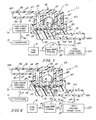
- Second roll-over valve 132 is configured to provide means in fluid-conducting passageway 15 for blocking flow of pressurized fuel vapor discharged from fuel tank vapor space 140 through fluid-conducting passageway 15 and tank port 147t to internal space 147s formed in flow-control housing 147 whenever second roll-over valve 132 is tilted at least a selected number of degrees from a normal upright position so that fuel vapor from fuel tank vapor space 140 is unable to flow through fuel-conducting passageway 15 to reach internal space 147s in flow-control housing 147.
- fuel tank 14 includes an interior region containing liquid fuel 24. Vapor space 140 is provided in that interior region above liquid fuel 24 and below top walls 141, 142 of fuel tank 14.
- a filler neck 30 is coupled to fuel tank 14 and formed to include an inlet 32 sized to receive a fuel- dispensing pump nozzle 34 coupled to fuel supply 35 after removal of a filler neck closure 36 from filler neck 30.
- Air/vapor flow regulator 112 even though located in a flow controller 111 that is remote from fuel tank 14, is configured to sense pressure and vacuum conditions in vapor space 140 of fuel tank 14. Air/vapor flow regulator 112 in flow controller 111 provides means for allowing ambient air 100 flowing From atmosphere 17 through canister 16 to pass through first and second roll-over valves 131, 132 into vapor space 140 whenever a vacuum extant in fuel tank vapor space 140 exceeds a predetermined vacuum level as suggested, for example, in Fig. 4.
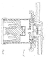
- Flow-control housing 147 also includes a cover tube 128 coupled to canister conduit 118 and formed to include a fluid-transfer passageway 146 terminating at canister port 147c and interconnecting central vent chamber 144 and canister conduit 118 in fluid communication.
- central vent chamber 144, vent passageway 124, and fluid- transfer passageway 146 cooperate to define interior space 147s of flow-control housing 147.
- first and second rings 181, 182 are included in flow-control housing 147 and in central vent chamber 144.
- First ring 181 surrounds second ring 182 and is concentric with second ring 182 to define an annular space 183 therebetween.
- First ring 181 forms an annular outer side wall of cover 126 as suggested in Fig. 2.
- One or more slots 84 are formed in second ring 182 to allow air and vapor flow from interior region 85 defined by second ring 182 and fluid-transfer passageway 146 and canister port 147c provided therein.
- Air 100 and fuel vapor 101, 102 e.g., mixture 103 can flow through slots 84 during venting activity as suggested, for example, in Figs.3 and 4.
- sealing disk 90 With very little flow, there is a pressure drop created across sealing disk 90 which will urge sealing disk 90 into contact with ball 93. If the sealing disk 90 is allowed to move too far away from ball 93, it may be that when there is a following instance of pressure sealing disk 90 may not move to the closed position for a "pressure-hold" function.
- Overfill-protection ball 93 normally remains in a port-closing position above vent port 92 as shown in Fig.2 during and after fuel tank re-fueling. Sealing disk 90 will thus remain normally in the "horizontal" orientation shown in Fig.2 owing, in part, to "stiffness" of the flexible sealing disk 90 and a “bed” of pressurized fuel vapor underneath sealing disk 90 during normal pressure/vacuum conditions.
- sealing disk 90 In contrast, should there be an unwanted vacuum in fuel tank 14, a central portion of sealing disk 90 will be drawn downwardly in open spaces provided above ribs 94 under a suction force established by a vacuum (e.g., high vacuum conditions 202) extant in vapor space 140 of fuel tank 14 as shown, for example, in Figs.1 and 4. In this event, pin 187 will function to support the weight of ball 93. A central portion of sealing disk 90 unsupported by ribs 94 will flex away from ball 93 and allow flow of ambient air 100 from atmosphere 17 past ball 93 and through annular channel 95 associated with vent port 92 and through interior port 152, vent passageway 124, etc., into fuel tank 14 to relieve unwanted vacuum conditions in fuel tank 14.
- a vacuum e.g., high vacuum conditions 202
- vent conduit 200 Any pressurized fuel vapor 103 extant in vent conduit 200 is free to pass through vent passageway 224 in base tube 222, vent port 252, central flow orifice 206 in tubular stem 205, and central aperture 291 formed in sealing disk 290 to reach the portion of vent-control chamber 204 above sealing disk 290 and below top wall 210a of lid 210.
- This pressurized fuel vapor 103 exerts a downward closing force "F CLOSE " on sealing disk 290 to retain that disk in the orifice-closing position shown in Fig.5.
- tubular stem 205 of overfill-protection device 293 is drawn downwardly to engage frustoconical seat 251 and any negative pressure from fuel tank 14 in vent conduit 200, vent passageway 224, and central flow aperture 206 is transferred through central aperture 291 in sealing disk 290 and exerts an upward opening force "F OPEN " applied to the upwardly facing surface of sealing disk 290.
- This suction force lifts sealing disk 290 upwardly as suggested diagrammatically in Fig.7 to allow air 100 to flow from fuel vapor recovery canister 16 underneath sealing disk 290 in vent-control chamber 204 through flow controller 211 to reach fuel tank 14.
- overfill-protection device 393 is a two-part device comprising a lid 310 and a lid support including an annular flange 308 and a downwardly extending tubular stem 305 terminating at a hemispherical sealing surface 307.
- Overfill-protection device 393 has a T-shaped cross section as shown, for example, in Fig.8.
- One or more stem guide posts 220a are appended to an interior surface of base 220 and arranged to extend upwardly toward lid 310 and to provide means for guiding movement of tubular stem 305 toward and away from base 220.
- Base 220 is formed to include frustoconical scat 251 for providing an opening into vent port 252 and mating with hemispherical sealing surface 307 to establish a sealed connection therebetween as suggested, for example, in Figs.8 and 10.
- 100741 Inside central vent chamber 244 in flow-control housing 247 is an overfill-protection device 393 that cooperates with sealing disk 390 normally to "close" vent port 252 to block flow of air 100 and fuel vapor 101, 102 (e.g., mixture 103) between fuel tank 14 and file1 vapor recovery canister 16 through vent port 252 into and through central vent chamber 244, fluid-transfer passageway 246, and canister conduit 11 8.
- Such blockage occurs during and after tank refueling to prevent dissipation of residual tank pressure to fuel vapor recovery canister 16 and atmosphere 17.
- each fuel tank vent unit 21, 22, 23 contains a roll-over valve and is mounted in a different "location" on fuel tank 14 to allow discharge of pressurized fuel vapor from an interior region of fuel tank 14 that is associated with that roll-over valve location as long as the roll-over valve remains “upright.”
- Such residual pressure tends to form a pressure "barrier” that limits admission of liquid fuel into fuel tank 14 during tank re-fueling after the tank has already been filled to its maximum capacity.
- Roll-over valve 40 includes a housing 50 having a ceiling 49 formed to include an annular valve seat 51 defining a vent port 52 providing a passageway for communicating air 100 and fuel vapor 101 between an interior region 53 of housing 50 and central vent chamber 44 as illustrated in Fig.12. Housing 50 also is formed to include ports 54 providing openings from interior region 53 into vapor space 26. Roll-over valve 40 further includes a buoyant float 55 located in interior region 53, a compression spring 56 interposed between float 55 and a floor 57 of housing 50 and configured to provide means for lifting float 55 away from floor 57 during a vehicle rollover or tilting event, and a vent closure 58 for closing and re-opening vent port 52.
Applications Claiming Priority (2)
| Application Number | Priority Date | Filing Date | Title |
|---|---|---|---|
| US68829105P | 2005-06-07 | 2005-06-07 | |
| US72373505P | 2005-10-05 | 2005-10-05 |
Publications (2)
| Publication Number | Publication Date |
|---|---|
| EP1731343A2 true EP1731343A2 (fr) | 2006-12-13 |
| EP1731343A3 EP1731343A3 (fr) | 2007-03-07 |
Family
ID=36992740
Family Applications (1)
| Application Number | Title | Priority Date | Filing Date |
|---|---|---|---|
| EP20060252951 Withdrawn EP1731343A3 (fr) | 2005-06-07 | 2006-06-07 | Soupape de retournement et système combiné empêchant un remplissage excessif ainsi que la formation de vide |
Country Status (2)
| Country | Link |
|---|---|
| US (1) | US8286658B2 (fr) |
| EP (1) | EP1731343A3 (fr) |
Families Citing this family (15)
| Publication number | Priority date | Publication date | Assignee | Title |
|---|---|---|---|---|
| US8950382B2 (en) * | 2004-12-16 | 2015-02-10 | Raval A.C.S. Ltd. | Vehicle fuel system and components thereof |
| JP2008538601A (ja) * | 2005-04-20 | 2008-10-30 | ビーイー・インテレクチュアル・プロパティー・インコーポレイテッド | 飲料製造装置のための通気バルブ |
| US8231110B2 (en) * | 2010-05-28 | 2012-07-31 | Stoner Dale A | Retrofit roll-over valve for carburetor float bowl vent tube |
| US8813780B2 (en) * | 2010-10-26 | 2014-08-26 | Schiller Grounds Care, Inc. | Sealed, non-permeable fuel tank for spark-ignition motors |
| DE102011116941A1 (de) | 2011-10-26 | 2013-05-02 | Kautex Textron Gmbh & Co. Kg | Entlüftungsventil |
| EP2607135B1 (fr) * | 2011-12-22 | 2014-07-02 | Volvo Car Corporation | Soupape de système de ventilation de carburant |
| US9453583B1 (en) * | 2013-07-12 | 2016-09-27 | Best Fabrications Inc. | Vent for tank |
| US9822885B2 (en) | 2014-08-29 | 2017-11-21 | Automatic Switch Company | Flow rib in valves |
| US9708808B2 (en) * | 2015-05-21 | 2017-07-18 | Jay R. Smith Manufacturing Company | Trap primer |
| JP6147810B2 (ja) * | 2015-06-22 | 2017-06-14 | 本田技研工業株式会社 | 燃料遮断構造 |
| US9939073B2 (en) * | 2016-02-04 | 2018-04-10 | FlowTech Fueling, LLC | Breather check valve |
| FR3054609A1 (fr) * | 2016-07-29 | 2018-02-02 | Plastic Omnium Advanced Innovation & Res | Regulateur de debit de ventilation pour un reservoir pressurise de vehicule. |
| JP2021032146A (ja) * | 2019-08-23 | 2021-03-01 | 豊田合成株式会社 | 燃料遮断弁 |
| DE102019008185A1 (de) * | 2019-11-26 | 2021-05-27 | Klaus Heinrichs | Entlüftungsventil, insbesondere für Getriebe |
| CN114845898A (zh) * | 2019-12-24 | 2022-08-02 | 百乐仕株式会社 | 阀装置 |
Citations (8)
| Publication number | Priority date | Publication date | Assignee | Title |
|---|---|---|---|---|
| US4735226A (en) * | 1986-03-07 | 1988-04-05 | Stant Inc. | Anti-lift roll-over valve |
| US5518018A (en) * | 1994-11-14 | 1996-05-21 | Stant Manufacturing Inc. | Fuel tank venting control assembly |
| US5535772A (en) * | 1995-05-01 | 1996-07-16 | Stant Manufacturing Inc. | Tank venting control system |
| US5566705A (en) * | 1995-06-30 | 1996-10-22 | Stant Manufacturing Inc. | Snap-closure float valve assembly |
| US5666989A (en) * | 1994-11-08 | 1997-09-16 | Stant Manufacturing Inc. | Tank venting control assembly |
| US5687778A (en) * | 1995-05-01 | 1997-11-18 | Stant Manufacturing Inc. | Dual valve tank venting system |
| US5694968A (en) * | 1996-04-15 | 1997-12-09 | Stant Manufacturing Inc. | Tank venting control system |
| US20020062861A1 (en) * | 2000-10-19 | 2002-05-30 | Jeffrey Devall | Fuel tank vent control valve |
Family Cites Families (15)
| Publication number | Priority date | Publication date | Assignee | Title |
|---|---|---|---|---|
| US4317467A (en) * | 1980-07-10 | 1982-03-02 | Illinois Tool Works Inc. | Two-way pressure relief valve |
| US4694847A (en) * | 1986-03-07 | 1987-09-22 | Stant Inc. | Roll-over valve with sealing ball |
| US4716920A (en) * | 1987-01-08 | 1988-01-05 | Stant Inc. | Roll over fuel cap |
| US4753262A (en) * | 1987-02-06 | 1988-06-28 | G.T. Products, Inc. | Fuel system vent valve having roll-over closure with improved re-opening action for venting |
| US5099880A (en) * | 1989-03-24 | 1992-03-31 | Stant Inc. | Fuel tank venting control valve assembly |
| US5054508A (en) * | 1990-01-25 | 1991-10-08 | G.T. Products, Inc. | Fuel tank vent system and diaphragm valve for such system |
| JPH06156093A (ja) * | 1992-11-24 | 1994-06-03 | Aisan Ind Co Ltd | フロート付フューエルカットオフバルブ |
| US5253668A (en) * | 1993-02-18 | 1993-10-19 | G.T. Products, Inc. | Smooth-opening, low-hysteresis ball head valve |
| US5449029A (en) * | 1994-05-11 | 1995-09-12 | Stant Manufacturing Inc. | Fill limit valve assembly |
| US5584278A (en) * | 1994-12-15 | 1996-12-17 | Nissan Motor Co., Ltd. | System for controlling fuel vapor flow discharged from a fuel tank to a canister |
| DE60025825T2 (de) * | 1999-06-01 | 2006-08-10 | Stant Manufacturing Inc., Connersville | Verfahren zum formen einer entlüftungsvorrichtung für einen kraftstofftank |
| US6237604B1 (en) * | 1999-09-07 | 2001-05-29 | Scimed Life Systems, Inc. | Systems and methods for preventing automatic identification of re-used single use devices |
| CA2334149C (fr) * | 2000-02-03 | 2005-05-10 | Stant Manufacturing Inc. | Support soudable pour composant de systemes d'alimentation en carburant |
| US6779544B2 (en) * | 2001-03-02 | 2004-08-24 | Stant Manufacturing Inc. | Tank refueling shutoff valve and vent system |
| US6481592B2 (en) * | 2001-04-23 | 2002-11-19 | Stant Manufacturing Inc. | Fuel tank vent valve |
-
2006
- 2006-05-30 US US11/420,852 patent/US8286658B2/en active Active
- 2006-06-07 EP EP20060252951 patent/EP1731343A3/fr not_active Withdrawn
Patent Citations (8)
| Publication number | Priority date | Publication date | Assignee | Title |
|---|---|---|---|---|
| US4735226A (en) * | 1986-03-07 | 1988-04-05 | Stant Inc. | Anti-lift roll-over valve |
| US5666989A (en) * | 1994-11-08 | 1997-09-16 | Stant Manufacturing Inc. | Tank venting control assembly |
| US5518018A (en) * | 1994-11-14 | 1996-05-21 | Stant Manufacturing Inc. | Fuel tank venting control assembly |
| US5535772A (en) * | 1995-05-01 | 1996-07-16 | Stant Manufacturing Inc. | Tank venting control system |
| US5687778A (en) * | 1995-05-01 | 1997-11-18 | Stant Manufacturing Inc. | Dual valve tank venting system |
| US5566705A (en) * | 1995-06-30 | 1996-10-22 | Stant Manufacturing Inc. | Snap-closure float valve assembly |
| US5694968A (en) * | 1996-04-15 | 1997-12-09 | Stant Manufacturing Inc. | Tank venting control system |
| US20020062861A1 (en) * | 2000-10-19 | 2002-05-30 | Jeffrey Devall | Fuel tank vent control valve |
Also Published As
| Publication number | Publication date |
|---|---|
| EP1731343A3 (fr) | 2007-03-07 |
| US8286658B2 (en) | 2012-10-16 |
| US20060283501A1 (en) | 2006-12-21 |
Similar Documents
| Publication | Publication Date | Title |
|---|---|---|
| US8286658B2 (en) | Roll-over valve with shared overfill protection and vacuum relief | |
| US5028244A (en) | Tank venting control valve assembly | |
| US4790349A (en) | Tank pressure control system | |
| US5666989A (en) | Tank venting control assembly | |
| US4991615A (en) | Tank pressure control apparatus | |
| US5694968A (en) | Tank venting control system | |
| US5044389A (en) | High volume fuel vapor release valve | |
| US4694847A (en) | Roll-over valve with sealing ball | |
| US6578597B2 (en) | Fuel tank vent system with liquid fuel filter | |
| US7882862B2 (en) | Fuel and vapor vent management system for filler neck | |
| US8118051B2 (en) | Valve for the venting circuit of a liquid tank | |
| US6170510B1 (en) | Tank venting control system | |
| US4760858A (en) | Fuel vapor control valve | |
| US6035884A (en) | Liquid fuel baffle for vent apparatus | |
| US7823610B2 (en) | Refueling shut-off system with fill-limit vent valve | |
| EP1415845B1 (fr) | Partie collerette mobile pour un embout de remplissage sans bouchon | |
| US5687778A (en) | Dual valve tank venting system | |
| US5535772A (en) | Tank venting control system | |
| KR100846527B1 (ko) | 롤 오버 벤트 밸브 | |
| US5044397A (en) | Tank pressure control apparatus | |
| EP1199207A2 (fr) | Soupape de commande pour ventilation de réservoir à carburant | |
| CZ20013215A3 (cs) | Odvzduąňovací překlopný ventil, zabraňující přeplňování | |
| KR20120023775A (ko) | 동적 압력 방출이 일어나는 연료 증기 벤트 밸브 | |
| US20050126633A1 (en) | Fill limit vent valve | |
| KR20060102510A (ko) | 일체형 증기 벤트/팁핑 밸브 및 증기 저장 조립체 및 그제조 방법 |
Legal Events
| Date | Code | Title | Description |
|---|---|---|---|
| PUAI | Public reference made under article 153(3) epc to a published international application that has entered the european phase |
Free format text: ORIGINAL CODE: 0009012 |
|
| AK | Designated contracting states |
Kind code of ref document: A2 Designated state(s): AT BE BG CH CY CZ DE DK EE ES FI FR GB GR HU IE IS IT LI LT LU LV MC NL PL PT RO SE SI SK TR |
|
| AX | Request for extension of the european patent |
Extension state: AL BA HR MK YU |
|
| PUAL | Search report despatched |
Free format text: ORIGINAL CODE: 0009013 |
|
| AK | Designated contracting states |
Kind code of ref document: A3 Designated state(s): AT BE BG CH CY CZ DE DK EE ES FI FR GB GR HU IE IS IT LI LT LU LV MC NL PL PT RO SE SI SK TR |
|
| AX | Request for extension of the european patent |
Extension state: AL BA HR MK YU |
|
| AKX | Designation fees paid | ||
| 17P | Request for examination filed |
Effective date: 20070907 |
|
| RBV | Designated contracting states (corrected) |
Designated state(s): AT BE BG CH CY CZ DE DK EE ES FI FR GB GR HU IE IS IT LI LT LU LV MC NL PL PT RO SE SI SK TR |
|
| 17Q | First examination report despatched |
Effective date: 20071107 |
|
| REG | Reference to a national code |
Ref country code: DE Ref legal event code: 8566 |
|
| RAP1 | Party data changed (applicant data changed or rights of an application transferred) |
Owner name: STANT MANUFACTURING INC. |
|
| RAP1 | Party data changed (applicant data changed or rights of an application transferred) |
Owner name: STANT USA CORP. |
|
| STAA | Information on the status of an ep patent application or granted ep patent |
Free format text: STATUS: THE APPLICATION IS DEEMED TO BE WITHDRAWN |
|
| 18D | Application deemed to be withdrawn |
Effective date: 20100105 |