EP1730996B1 - Elektrischer fluidheizer - Google Patents
Elektrischer fluidheizer Download PDFInfo
- Publication number
- EP1730996B1 EP1730996B1 EP05740627A EP05740627A EP1730996B1 EP 1730996 B1 EP1730996 B1 EP 1730996B1 EP 05740627 A EP05740627 A EP 05740627A EP 05740627 A EP05740627 A EP 05740627A EP 1730996 B1 EP1730996 B1 EP 1730996B1
- Authority
- EP
- European Patent Office
- Prior art keywords
- heating element
- fluid heater
- electric fluid
- electrode surfaces
- heating elements
- Prior art date
- Legal status (The legal status is an assumption and is not a legal conclusion. Google has not performed a legal analysis and makes no representation as to the accuracy of the status listed.)
- Expired - Lifetime
Links
Images

Classifications
-
- H—ELECTRICITY
- H05—ELECTRIC TECHNIQUES NOT OTHERWISE PROVIDED FOR
- H05B—ELECTRIC HEATING; ELECTRIC LIGHT SOURCES NOT OTHERWISE PROVIDED FOR; CIRCUIT ARRANGEMENTS FOR ELECTRIC LIGHT SOURCES, IN GENERAL
- H05B3/00—Ohmic-resistance heating
- H05B3/40—Heating elements having the shape of rods or tubes
- H05B3/42—Heating elements having the shape of rods or tubes non-flexible
-
- H—ELECTRICITY
- H05—ELECTRIC TECHNIQUES NOT OTHERWISE PROVIDED FOR
- H05B—ELECTRIC HEATING; ELECTRIC LIGHT SOURCES NOT OTHERWISE PROVIDED FOR; CIRCUIT ARRANGEMENTS FOR ELECTRIC LIGHT SOURCES, IN GENERAL
- H05B2203/00—Aspects relating to Ohmic resistive heating covered by group H05B3/00
- H05B2203/021—Heaters specially adapted for heating liquids
-
- H—ELECTRICITY
- H05—ELECTRIC TECHNIQUES NOT OTHERWISE PROVIDED FOR
- H05B—ELECTRIC HEATING; ELECTRIC LIGHT SOURCES NOT OTHERWISE PROVIDED FOR; CIRCUIT ARRANGEMENTS FOR ELECTRIC LIGHT SOURCES, IN GENERAL
- H05B2203/00—Aspects relating to Ohmic resistive heating covered by group H05B3/00
- H05B2203/022—Heaters specially adapted for heating gaseous material
Definitions
- the invention relates to an electrical resistance heating element for heating flowing media.
- Electrical resistance heating elements in the form of honeycomb bodies, tube bundles or multi-hole plates are frequently used for heating flowing media such as air or non-conductive liquids such as silicone oil, glycol, hydraulic oil, gasoline or diesel fuel.
- a plurality of channels or bores is generally present in the resistance element through which the medium to be heated (fluid) can flow or is pumped through.
- the volume of the resistance heating element flows through the heating current more or less homogeneously and heats up.
- heat exchange takes place between the resistive element and the fluid. How much heat per unit time is delivered to the flowing medium depends, among other things, on the temperature difference between the resistance body and the fluid, the size of the heat exchange surface, the heat capacity of the medium and its flow velocity.
- the resistance element can deliver only as much heat per unit of time to the medium to be heated, as it can implement at the available operating voltage U to electrical power P.
- honeycomb radiators or tube bundles are metallized for electrical contacting at their opposite end faces according to the prior art, for example by screen printing or rolling process. It follows that the electrode area A is equal to the end face of the honeycomb body, reduced by the sum of the cross-sectional areas of the channels through which the medium flows. The length I of the current paths is identical to the length of the channels.
- the specific resistance of the Resistor materials can not be arbitrarily reduced, especially for ceramic resistance body with PTC characteristic, the practically reached lower limit is about 5 to 10 ⁇ * cm. This results in the production of honeycomb, tube bundle or multi-channel heaters two conflicts.
- a honeycomb body is presented, which is cut parallel to the electrode surfaces in two equal halves.
- the cut surfaces are metallized, connected to a pole of the voltage source and then reassembled.
- the second pole of the voltage source is located at the same time on the two outer electrode surfaces of this sandwich arrangement.
- the honeycomb halves electrically connected in this way have a four times lower electrical resistance than the simple honeycomb by doubling the electrode area while halving the conductor length.
- Disadvantage of this arrangement is the high production cost due to the additional separation and metallization and there are now joints within the channels. As a result of heavy avoidable geometry tolerances can occur at these joints to significant disturbances of the flow.
- the invention has for its object to provide an arrangement for electrical resistance heating, which is technologically easy to implement and with the same time high power densities can be achieved. It should be possible to tailor the channel cross-section and channel length with respect to heat and fluidic issues to the particular application, without the limitations of the metallization come into play.
- an electric fluid heater made of ceramic or polymer composite, consisting of at least one, provided with at least one channel heating element, each heating element is designed as a prismatic body and those two outer surfaces, between each of which all channels are arranged side by side, with Electrode surfaces are acted upon, so that a current flow between the electrode surfaces substantially transverse to the longitudinal axes of the channels is achieved in that at least one electrode surface of each heating element has a connection surface which is arranged on the adjacent, perpendicular right outer surface of the heating element.
- the particular advantage of the arrangement according to the invention is that any number of technologically identically manufactured, each rotated by the surface normal of the electrode surfaces by 180 ° heating elements, can be strung together.
- By the rotation and joining of the heating elements these can be joined together in the form of a parallel connection via the connection surfaces to form an electric fluid heater.
- the connection can be made by clamping, gluing or soldering.
- the heating elements are aligned exactly parallel.
- the electrical connection lines can simultaneously serve for the mechanical fixing of the heating elements.
- the flow of current through the honeycomb body is transverse to the flow direction of the fluid.
- the electrode spacing results from the sum of Cell size plus double wall thickness. He is thus much shorter than at Stirnbibtechnik. However, it does not reach the critical values as in internal metallization.
- the process reliability is higher than the inner metallization, as any existing holes or weak points in individual honeycomb walls can not directly lead to short circuit or voltage breakdown.
- Low resistance values result from the parallel connection of the comparatively short current paths through the channel walls of individual segments and the additional parallel connection of the segments.
- the arrangement according to the invention makes it possible to produce profiles in the form of single-row honeycomb segments in the extrusion process. These can be precisely and inexpensively cut to length after sintering. For metallization for applying the electrode surfaces, there are proven methods of screen printing or sputtering.
- the heating element 1 consists of its essential components, the channels 2 and the two opposite electrode surfaces 3, 4.
- the first electrode surface 3 is in this case with the pad 5 in combination.
- the second electrode surface 4 is in this embodiment with no pad 5 in conjunction. However, it is readily possible to provide this second electrode surface 4 with a second connection surface, but then the first connection surface 5 exactly opposite.
- the shaped body of the heating element 1 is preferably made of PTC ceramic, which has been prepared on the basis of semiconducting barium titanate and by addition of organic binders and plasticizers to a rigid plastic mass. In the extrusion process, the prismatic molded bodies are produced from each with a series of parallel channels 2 and sintered therefrom. These are cut to length after sintering with diamond blades. By screen printing, metal spraying or Sputtering the moldings are provided with suitable structured metal electrodes, such as aluminum or silver.
- the heating elements 1 produced in this way are each rotated by 180 °, based on the surface normal of the electrode surfaces 3, 4, and lined up.
- a stack of heating elements 1 wherein in each case the first electrode surface 3 with the second electrode surface 4 of the adjacent heating element 1 come into contact.
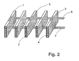
- Fig. 2 via the upper feed line 6, the contact with the first electrode surfaces 3 and thus also to the adjacent second electrode surfaces 4 via the pads 5 z. B. made by soldering.
- Via the lower supply line 7, the contact is produced analogously to the first electrode surfaces 3 and thus in turn to the second electrode surfaces 4 via the connection surfaces 5.
- the connection can be done in addition to soldering by gluing or clamping.
- a parallel connection of the heating elements 1 is realized. To avoid short circuits between the electrode surfaces 4 and the pads 5 and the leads 6, 7, it is known to provide appropriate insulation.
- a PTC ceramic material with a specific cold resistance of 10 ⁇ * cm to a heating element 1 according to Fig. 1 formed with six parallel channels 2 of 20 mm channel length and 2 x 2 mm channel cross-section and 0.4 mm wall thickness, this reaches in metallization with lateral connection electrodes according to Fig. 2 a cold resistance of about 5 ⁇ .
- the parallel connection of 5 such honeycomb segments leads to a total resistance of 1 ⁇ .
- an operating voltage of 12 V a power consumption of 144 watts is possible.
Landscapes
- Resistance Heating (AREA)
- Instantaneous Water Boilers, Portable Hot-Water Supply Apparatuses, And Control Of Portable Hot-Water Supply Apparatuses (AREA)
Description
- Die Erfindung betrifft ein elektrisches Widerstandsheizelement für die Beheizung strömender Medien.
- Elektrische Widerstandsheizelemente in Form von Wabenkörpern, Rohrbündeln oder Mehrlochplatten werden häufig zum Beheizen strömender Medien wie Luft oder nichtleitenden Flüssigkeiten wie Silikonöl, Glykol, Hydrauliköl, Benzin oder Dieselkraftstoff genutzt. Dabei ist in der Regel in dem Widerstandselement eine Vielzahl von Kanälen oder Bohrungen vorhanden, durch die das zu beheizende Medium (Fluid) hindurchströmen kann bzw. hindurchgepumpt wird. Das Volumen des Widerstandsheizelementes wird mehr oder weniger homogen vom Heizstrom durchflossen und erwärmt sich. An der Oberfläche der Kanäle oder Bohrungen findet ein Wärmeaustausch zwischen dem Widerstandselement und dem Fluid statt. Wie viel Wärme pro Zeiteinheit an das strömende Medium abgegeben wird, hängt unter anderem von der Temperaturdifferenz zwischen Widerstandskörper und Fluid, von der Größe der Wärmeaustauschfläche, von der Wärmekapazität des Mediums und von dessen Strömungsgeschwindigkeit ab. Selbstverständlich kann das Widerstandselement nur so viel Wärme pro Zeiteinheit an das zu beheizende Medium abgeben, wie es bei der verfügbaren Betriebsspannung U an elektrischer Leistung P umsetzen kann. Die Leistung P bestimmt sich aus P = U2/R. Das heißt, für hohe Heizleistungen muss das Widerstandsheizelement einen niedrigen elektrischen Widerstand R aufweisen. Der Widerstand des Heizelementes wird vom spezifischen Widerstand ρ des Materials, von der Querschnittsfläche A des Heizers und der Länge I der Strompfade bestimmt:

- Aus Gründen der einfachen technologischen Handhabung werden nach dem Stand der Technik prismatische Wabenheizkörper oder auch Rohrbündel zur elektrischen Kontaktierung an ihren gegenüberliegenden Stirnseiten metallisiert, beispielsweise im Siebdruck- oder Walzverfahren. Daraus ergibt sich, dass die Elektrodenfläche A gleich der Stirnfläche der Wabenkörper, vermindert um die Summe der Querschnittsflächen der Kanäle, durch die das Medium hindurchfließt, ist. Die Länge I der Strompfade ist identisch mit der Länge der Kanäle. Der spezifische Widerstand der Widerstandsmaterialien lässt sich nicht beliebig vermindern, insbesondere für keramische Widerstandskörper mit PTC-Charakteristik liegt die praktisch erreichte Untergrenze bei etwa 5 bis 10 Ω*cm. Daraus ergeben sich bei der Herstellung von Waben, Rohrbündel- oder Mehrkanalheizern zwei Konflikte.
- Für einen günstigen Wärmeübergang wird eine ausreichend große Kanallänge angestrebt, wodurch sich aber der elektrische Widerstand erhöht und die Heizleistung eingeschränkt wird.
- Für einen niedrigen Strömungswiderstand des Wabenheizers sollte der durchströmbare Flächenanteil der Wabe möglichst hoch sein. Das heißt aber, dass der verfügbare Flächenanteil für die Anschlusselektroden kleiner wird, was zu einer zusätzlichen Begrenzung der elektrischen Leistungsaufnahme führt.
- Zur Lösung des Konflikts wird beispielsweise durch die
DE 100 60 301 A1 vorgeschlagen, die Kanäle der Wabenkörper innen zu metallisieren, wobei benachbarte Kanäle auf unterschiedlicher Polarität liegen und die Länge der Strompfade gleich der Wandstärke der Kanäle ist. Diese Lösungsvorschläge erfordern aufwendige technologische Maßnahmen, um ausreichend breite Isolierabstände bzw. Kriechstrecken zwischen Elektroden unterschiedlicher Polarität zu gewährleisten. Außerdem kann es bei geringen Wandstärken, die eigentlich strömungstechnisch vorteilhaft sind, zu Ausfällen infolge von Spannungsdurchschlägen kommen. Zusätzlich besteht bei Wabenkörpern mit Innenmetallisierung das Problem, dass aus technologischen Gründen die Zellweite nach unten und die Kanallänge nach oben eingeschränkt wird. - In der
DE 102 01 262 A1 wird ein Wabenkörper vorgestellt, der parallel zu den Elektrodenflächen in zwei gleich große Hälften geschnitten wird. Die Schnittflächen werden metallisiert, mit einem Pol der Spannungsquelle verbunden und anschließend wieder zusammengefügt. Der zweite Pol der Spannungsquelle liegt gleichzeitig an den beiden äußeren Elektrodenflächen dieser Sandwich-Anordnung. Die auf diese Weise elektrisch parallel geschalteten Wabenhälften haben durch die Verdopplung der Elektrodenfläche bei gleichzeitiger Halbierung der Leiterlänge einen viermal geringeren elektrischen Widerstand als die einfache Wabe. Nachteil dieser Anordnung ist der hohe Herstellungsaufwand durch die zusätzlichen Trenn- und Metallisierungsschritte und es befinden sich innerhalb der Kanäle nunmehr Fügestellen. Infolge von schwer vermeidbaren Geometrietoleranzen kann es an diesen Fügestellen zu erheblichen Störungen des Strömungsverlaufes kommen. - Mit der
US 4,939,349 wird ein weiterer prinzipieller Lösungsansatz für elektrische Widerstandsheizer aufgezeigt. Zum Zweck der elektrischen Kontaktierung sind jeweils zwei Außenflächen metallisiert, so dass der elektrische Strom senkrecht zur Richtung des strömenden Mediums in den Kanälen fließen kann und die einzelnen Heizelemente in einfacher Weise von außen kontaktiert werden. Bei dieser Anordnung können die Heizelemente nur aneinander gereiht werden und somit liegen die Kanäle alle in einer Ebene. Um die lineare Ausdehnung der aneinander gereihten Heizelemente zu begrenzen, müssen die Heizelemente zwischen den Elektrodenflächen eine relativ große geometrische Ausdehnung haben, damit in den durchströmten Kanälen eine ausreichende Wärmeaustauschfläche zum strömenden Medium zur Verfügung steht. Daraus ergibt sich, dass die Strompfade zwischen den Elektrodenflächen vergleichsweise lang sind. Da der spezifische Widerstand des Keramikmaterials aus festkörperphysikalischen Gründen nicht beliebig niedrig eingestellt werden kann, ist eine solche Anordnung wegen des vergleichsweise hohen elektrischen Widerstandes in ihrer elektrischen Leistungsaufnahme eingeschränkt. - Der Erfindung liegt die Aufgabe zugrunde, eine Anordnung für elektrische Widerstandsheizelemente zu schaffen, die technologisch einfach realisierbar ist und mit der zugleich hohe Leistungsdichten erreicht werden können. Es soll möglich sein, Kanalquerschnitt und Kanallänge im Hinblick auf wärme- und strömungstechnische Belange auf den jeweiligen Anwendungsfall zuzuschneiden, ohne dass dabei die Einschränkungen der Metallisierungstechnologie zum Tragen kommen.
- Erfindungsgemäß wird diese Aufgabe bei einem elektrischer Fluidheizer aus Keramik- oder Polymerverbundwerkstoff, bestehend aus mindestens einem, mit mindestens einem Kanal versehenem Heizelement, wobei jedes Heizelement als prismatischer Körper ausgebildet ist und diejenigen zwei Außenflächen, zwischen denen jeweils alle Kanäle nebeneinander liegend angeordnet sind, mit Elektrodenflächen beaufschlagt sind, so dass ein Stromfluss zwischen den Elektrodenflächen im Wesentlichen quer zu den Längsachsen der Kanäle erfolgt, dadurch gelöst, dass mindestens eine Elektrodenfläche eines jeden Heizelementes eine Anschlussfläche aufweist, die auf der angrenzenden, senk rechten Außenfläche des Heizelementes angeordnet ist. Beim Aufbringen der Anschlussflächen ist dabei zur jeweils anderen Elektrodenfläche ein auf den jeweiligen Anwendungsfall zugeschnittener, mehr oder weniger breiter Isolationsrand einzuhalten. Der besondere Vorteil der erfindungsgemäßen Anordnung besteht darin, dass beliebig viele technologisch identisch hergestellte, jeweils um die Flächennormale der Elektrodenflächen um 180° gedrehte Heizelemente, aneinander gereiht werden können. Durch die Drehung und Aneinanderfügung der Heizelemente können diese untereinander in Form einer Parallelschaltung über die Anschlussflächen zu einem elektrischen Fluidheizer zusammengefügt werden. Die Verbindung kann dabei durch Klemmen, Kleben oder Löten erfolgen. Dabei werden die Heizelemente exakt parallel ausgerichtet. In einer vorteilhaften erfindungsgemäßen Ausführung können die elektrischen Verbindungsleitungen gleichzeitig zur mechanischen Fixierung der Heizelemente dienen. Der Stromfluss durch den Wabenkörper erfolgt quer zur Strömungsrichtung des Fluides. Der Elektrodenabstand ergibt sich aus der Summe von Zellweite plus doppelter Wandstärke. Er ist damit um ein Vielfaches kürzer als bei Stirnkontaktierung. Er erreicht aber nicht die kritischen Werte wie bei einer Innenmetallisierung.
- Die Prozesssicherheit ist gegenüber der Innenmetallisierung höher, da eventuell vorhandene Löcher oder Schwachstellen in einzelnen Wabenwänden nicht unmittelbar zu Kurzschluss oder Spannungsdurchbruch führen können. Niedrige Widerstandswerte ergeben sich aus der Parallelschaltung der vergleichsweise kurzen Strompfade durch die Kanalwände einzelner Segmente sowie der zusätzlichen Parallelschaltung der Segmente. Durch die erfindungsgemäße Anordnung ist es möglich, im Extrudierverfahren Profile in Form einreihiger Wabensegmente herzustellen. Diese können präzise und kostengünstig nach dem Sintern auf Länge geschnitten werden. Für die Metallisierung zum Aufbringen der Elektrodenflächen gibt es erprobte Verfahren der Siebdruck- oder Sputtertechnik.
- Die Erfindung soll nachstehend anhand von Ausführungsbeispielen näher erläutert werden. Die Zeichnungen zeigen:
- Fig.1
- schematische Darstellung eines Heizelements
- Fig. 2
- Explosivdarstellung des erfindungsgemäßen elektrischen Fluidheizers
- Wie aus
Fig. 1 ersichtlich, besteht das Heizelement 1 aus seinen wesentlichen Bestandteilen, den Kanälen 2 und den beiden sich gegenüberliegenden Elektrodenflächen 3, 4. Die erste Elektrodenfläche 3 steht dabei mit der Anschlussfläche 5 in Verbindung. Die zweite Elektrodenfläche 4 steht in dieser Ausführungsform mit keiner Anschlussfläche 5 in Verbindung. Es ist jedoch ohne weiteres möglich, auch diese zweite Elektrodenfläche 4 mit einer zweiten Anschlussfläche, dann jedoch der ersten Anschlussfläche 5 genau gegenüberliegendend, zu versehen. Der Formkörper des Heizelementes 1 besteht vorzugsweise aus PTC-Keramik, die auf Basis von halbleitendem Bariumtitanat und durch Zusatz organischer Bindemittel und Plastifikatoren zu einer steifplastischen Masse aufbereitet wurde. Im Extrusionsverfahren werden daraus die prismatischen Formkörper mit jeweils einer Reihe von parallelen Kanälen 2 hergestellt und gesintert. Diese werden nach dem Sintern mit Diamanttrennscheiben auf Länge geschnitten. Durch Siebdrucken, Metallspritzen oder Sputtern werden die Formkörper mit geeigneten strukturierten Metallelektroden, beispielsweise aus Aluminium oder Silber, versehen. - Die so hergestellten Heizelemente 1 werden jeweils um 180°, bezogen auf die Flächennormale der Elektrodenflächen 3, 4, gedreht und aneinander gereiht. Somit entsteht ein Stapel von Heizelementen 1, wobei jeweils die erste Elektrodenfläche 3 mit der zweiten Elektrodenfläche 4 des benachbarten Heizelementes 1 in Kontakt treten. Wie aus
Fig. 2 ersichtlich, wird über die obere Zuleitung 6 der Kontakt zu den ersten Elektrodenflächen 3 und damit auch zu den anliegenden zweiten Elektrodenflächen 4 über die Anschlussflächen 5 z. B. durch Löten hergestellt. Über die untere Zuleitung 7 wird der Kontakt analog zu den ersten Elektrodenflächen 3 und damit wiederum zu den zweiten Elektrodenflächen 4 über die Anschlussflächen 5 hergestellt. Die Verbindung kann neben dem Löten auch durch Kleben oder Klemmen erfolgen. Durch genau diesen Aufbau ist eine Parallelschaltung der Heizelemente 1 realisiert. Um Kurzschlüsse zwischen den Elektrodenflächen 4 und den Anschlussflächen 5 bzw. den Zuleitungen 6, 7 zu vermeiden, sind bekanntermaßen entsprechende Isoliermaßnahmen zu treffen. - Wird beispielsweise ein PTC-Keramikwerkstoff mit einem spezifischen Kaltwiderstand von 10 Ω*cm zu einem Heizelement 1 gemäß
Fig. 1 mit sechs parallelen Kanälen 2 von 20 mm Kanallänge und 2x2 mm Kanalquerschnitt sowie 0,4 mm Wandstärke geformt, so erreicht dieser bei Metallisierung mit seitlichen Anschlusselektroden gemäßFig. 2 einen Kaltwiderstand von etwa 5 Ω. Die Parallelschaltung von 5 derartigen Wabensegmenten führt zu einem Gesamtwiderstand von 1 Ω. Bei einer Betriebsspannung von 12 V ist damit eine Leistungsaufnahme von 144 Watt möglich. -
- 1.
- Heizelement
- 2.
- Kanal
- 3.
- erste Elektrodenfläche
- 4.
- zweite Elektrodenfläche
- 5.
- Anschlussfläche
- 6.
- obere Zuleitung
- 7.
- untere Zuleitung
Claims (7)
- Elektrischer Fluidheizer aus Keramik- oder Polymerverbundwerkstoff bestehend aus mindestens einem, mit mindestens einem Kanal (2) versehenem Heizelement (1), wobei jedes Heizelement (1) als prismatischer Körper ausgebildet ist und diejenigen zwei Außenflächen, zwischen denen jeweils alle Kanäle (2) nebeneinander liegend angeordnet sind, mit Elektrodenflächen beaufschlagt sind, so dass ein Stromfluss zwischen den Elektrodenflächen (3, 4) im Wesentlichen quer zu den Längsachsen der Kanäle (2) erfolgt, dadurch gekennzeichnet,
dass mindestens eine Elektrodenfläche (3 und/oder 4) eines jeden Heizelementes (1) eine Anschlussfläche (5) aufweist, die auf der angrenzenden, senk rechten Außenfläche des Heizelementes (1) angeordnet ist. - Elektrischer Fluidheizer nach Anspruch 1, dadurch gekennzeichnet,
dass die Heizelemente (1) als flache prismatische Körper mit jeweils mehreren parallelen Kanälen (2), deren Längsachsen in einer Ebene liegen, ausgebildet sind. - Elektrischer Fluidheizer nach Anspruch 1 und 2, dadurch gekennzeichnet,
dass die Heizelemente (1) jeweils verdreht um 180° um die Flächennormale der Elektrodenflächen (3, 4) aneinander gereiht angeordnet sind und die Anschlussflächen (5) im Klemm-, Löt- oder Klebverfahren über elektrische Zuleitungen mit dem Plus- bzw. Minuspol der Versorgungsspannung verbundbar sind. - Elektrischer Fluidheizer nach Anspruch 1 und 2, dadurch gekennzeichnet,
dass die Heizelemente (1) jeweils verdreht um 180° um die Flächennormale der Elektrodenflächen (3, 4) aneinander gereiht angeordnet sind und die Anschlussflächen (5) im Klemm-, Löt- oder Klebverfahren über elektrische Zuleitungen an Phase und Nullleiter einer Wechselspannungsquelle anschliessbar sind. - Elektrischer Fluidheizer nach Anspruch 1, dadurch gekennzeichnet,
dass die Heizelemente (1) aus einem Material bestehen, das in einem vorwählbaren Temperaturintervall einen positiven Temperaturkoeffizienten des elektrischen Widerstandes aufweist. - Elektrischer Fluidheizer nach Anspruch 1, dadurch gekennzeichnet,
dass das Heizelement (1) aus halbleitender Bariumtitanatkeramik mit positivem Temperaturkoeffizienten des elektrischen Widerstandes besteht. - Elektrischer Fluidheizer nach Anspruch 1, dadurch gekennzeichnet,
dass das Heizelement (1) aus einem Polymerverbundwerkstoff mit positivem Temperaturkoeffizienten des elektrischen Widerstandes besteht.
Applications Claiming Priority (2)
| Application Number | Priority Date | Filing Date | Title |
|---|---|---|---|
| DE102004016434A DE102004016434B4 (de) | 2004-03-31 | 2004-03-31 | Elektrischer Fluidheizer |
| PCT/DE2005/000586 WO2005096672A1 (de) | 2004-03-31 | 2005-03-31 | Elektrischer fluidheizer |
Publications (2)
| Publication Number | Publication Date |
|---|---|
| EP1730996A1 EP1730996A1 (de) | 2006-12-13 |
| EP1730996B1 true EP1730996B1 (de) | 2008-05-07 |
Family
ID=34966900
Family Applications (1)
| Application Number | Title | Priority Date | Filing Date |
|---|---|---|---|
| EP05740627A Expired - Lifetime EP1730996B1 (de) | 2004-03-31 | 2005-03-31 | Elektrischer fluidheizer |
Country Status (6)
| Country | Link |
|---|---|
| US (1) | US20070189741A1 (de) |
| EP (1) | EP1730996B1 (de) |
| AT (1) | ATE394903T1 (de) |
| DE (2) | DE102004016434B4 (de) |
| ES (1) | ES2306142T3 (de) |
| WO (1) | WO2005096672A1 (de) |
Families Citing this family (10)
| Publication number | Priority date | Publication date | Assignee | Title |
|---|---|---|---|---|
| US20110202019A1 (en) * | 2009-12-04 | 2011-08-18 | Mt Industries, Inc. | Hand held skin treatment spray system with air heating element |
| JP5919199B2 (ja) * | 2010-12-24 | 2016-05-18 | 日本碍子株式会社 | ハニカム構造体 |
| JP5883299B2 (ja) * | 2011-03-24 | 2016-03-09 | 日本碍子株式会社 | 潤滑系流体の加熱用ヒーター |
| JP6901722B2 (ja) * | 2017-03-30 | 2021-07-14 | 東京エレクトロン株式会社 | 流体加熱器、流体制御装置、および流体加熱器の製造方法 |
| IT201800005496A1 (it) * | 2018-05-18 | 2019-11-18 | Dispositivo riscaldatore elettrico, particolarmente ad effetto ptc | |
| CN114761736B (zh) * | 2019-12-04 | 2024-06-14 | 格兰富控股公司 | 加热系统和制造加热系统的方法 |
| CN115299178A (zh) | 2020-03-23 | 2022-11-04 | 康泰尔有限公司 | 加热元件 |
| JP2025513732A (ja) | 2022-03-30 | 2025-04-30 | カンタール・アクチボラグ | 加熱要素および流体加熱器ならびに流体を加熱するための方法 |
| EP4620263A1 (de) | 2022-11-17 | 2025-09-24 | Kanthal AB | Heizelement und fluiderhitzer sowie verfahren zum erwärmen von fluid |
| CN116287519B (zh) * | 2023-02-15 | 2024-08-27 | 钢研晟华科技股份有限公司 | 一种纯氢竖炉还原高温氢气电加热装置及方法 |
Family Cites Families (13)
| Publication number | Priority date | Publication date | Assignee | Title |
|---|---|---|---|---|
| DE2432904A1 (de) * | 1973-07-19 | 1975-02-06 | Atomic Energy Authority Uk | Heizelement zum erhitzen von stroemungsmitteln |
| US3995143A (en) * | 1974-10-08 | 1976-11-30 | Universal Oil Products Company | Monolithic honeycomb form electric heating device |
| US5227946A (en) * | 1981-04-02 | 1993-07-13 | Raychem Corporation | Electrical device comprising a PTC conductive polymer |
| US4505107A (en) * | 1981-10-26 | 1985-03-19 | Nippondenso Co., Ltd. | Exhaust gas cleaning apparatus |
| DE3204207C2 (de) * | 1982-02-08 | 1985-05-23 | Siemens AG, 1000 Berlin und 8000 München | Elektrischer Widerstand mit einem keramischen PTC-Körper und Verfahren zu seiner Herstellung |
| US4791276A (en) * | 1982-04-16 | 1988-12-13 | Raychem Corporation | Elongate electrical assemblies |
| US4939349A (en) * | 1989-06-23 | 1990-07-03 | Uppermost Electronic Industries Co., Ltd. | Ceramic thermistor heating element |
| JP3001281B2 (ja) * | 1991-03-06 | 2000-01-24 | 日本碍子株式会社 | ハニカムモノリスヒータ |
| US5192853A (en) * | 1991-10-22 | 1993-03-09 | Yeh Yuan Chang | Heating set having positive temperatue coefficient thermistor elements adhesively connected to heat radiator devices |
| JP2962605B2 (ja) * | 1991-11-28 | 1999-10-12 | 株式会社デンソー | Ptc発熱体 |
| DE4230848C1 (de) * | 1992-09-15 | 1993-12-23 | Siemens Matsushita Components | Vielfachkaltleiter |
| DE10060301B4 (de) * | 2000-12-05 | 2011-11-17 | Fraunhofer-Gesellschaft zur Förderung der angewandten Forschung e.V. | Elektrisches Widerstandsheizelement mit einem Wabenkörper |
| DE10201262B4 (de) * | 2002-01-15 | 2006-09-07 | Webasto Ag | Widerstandsheizelement |
-
2004
- 2004-03-31 DE DE102004016434A patent/DE102004016434B4/de not_active Expired - Fee Related
-
2005
- 2005-03-31 WO PCT/DE2005/000586 patent/WO2005096672A1/de not_active Ceased
- 2005-03-31 EP EP05740627A patent/EP1730996B1/de not_active Expired - Lifetime
- 2005-03-31 DE DE502005003996T patent/DE502005003996D1/de not_active Expired - Lifetime
- 2005-03-31 ES ES05740627T patent/ES2306142T3/es not_active Expired - Lifetime
- 2005-03-31 AT AT05740627T patent/ATE394903T1/de not_active IP Right Cessation
- 2005-03-31 US US11/547,150 patent/US20070189741A1/en not_active Abandoned
Also Published As
| Publication number | Publication date |
|---|---|
| US20070189741A1 (en) | 2007-08-16 |
| ES2306142T3 (es) | 2008-11-01 |
| EP1730996A1 (de) | 2006-12-13 |
| DE102004016434A1 (de) | 2005-11-10 |
| DE502005003996D1 (de) | 2008-06-19 |
| WO2005096672A1 (de) | 2005-10-13 |
| ATE394903T1 (de) | 2008-05-15 |
| DE102004016434B4 (de) | 2006-01-05 |
Similar Documents
| Publication | Publication Date | Title |
|---|---|---|
| EP2752084B1 (de) | Elektrische heizeinheit, heizvorrichtung für ein fahrzeug und verfahren zur herstellung einer heizeinheit | |
| EP1988749B1 (de) | Elektrische Heizvorrichtung | |
| EP3631317A1 (de) | Elektrisches heizgerät, verfahren zur herstellung und zum betreiben sowie verwendung eines solchen heizgeräts | |
| EP0194507B1 (de) | Heizelement zum Erwärmen von strömenden, insbesondere gasförmigen Medien | |
| DE102018215398A1 (de) | Elektrische Heizeinrichtung | |
| EP2165379A1 (de) | Elektrochemische energiespeichereinheit | |
| DE102004016434B4 (de) | Elektrischer Fluidheizer | |
| EP1182908A1 (de) | PTC-Heizvorrichtung mit Klebestoff | |
| DE102015217790B4 (de) | Anordnung zur Kühlung von Batteriezellen eines Antriebsenergiespeichers eines Kraftfahrzeuges | |
| WO2004080738A1 (de) | Elektrische heizeinrichtung, insbesondere für kraftfahrzeuge | |
| DE10201262B4 (de) | Widerstandsheizelement | |
| EP3864262B1 (de) | Vorrichtung zur abgasbehandlung | |
| EP3494294B1 (de) | Elektrisch beheizbarer wabenkörper zur abgasbehandlung mit einer mehrzahl von heizelementen | |
| EP4012856B1 (de) | Elektrodenanordnung für eine ionisationsvorrichtung | |
| EP1714810B1 (de) | Elektrischer Zuheizer für eine Heizungs- oder Klimaanlage eines Kraftfahrzeugs | |
| DE10060301B4 (de) | Elektrisches Widerstandsheizelement mit einem Wabenkörper | |
| EP1497594B1 (de) | ZU HEIZZWECKEN DIENENDER WÄRMEüBERTRAGER MIT ELEKTRISCHER HEIZEINRICHTUNG | |
| DE102010020070A1 (de) | Heizmodul zur Erwärmung strömender Medien und Verfahren zu seiner Herstellung | |
| DE102021104263A1 (de) | Heizeinrichtung zur Erwärmung eines Wärmeträgermediums, insbesondere in einem Fahrzeug | |
| EP1912028B1 (de) | Elektrische Heizungsanordnung, insbesondere für ein Kraftfahrzeug | |
| EP3417673B1 (de) | Wärmetauschersystem | |
| DE102007017623A1 (de) | Montageplatte für elektrische oder elektronische Bauteile | |
| DE102023127589B3 (de) | Elektrisches Heizaggregat für das Aufheizen von Abgas in einem Abgasstrang | |
| DE19712178C2 (de) | Elektrische Heizeinrichtung, insbesondere für ein Kraftfahrzeug | |
| DE202023105817U1 (de) | Elektrisches Heizaggregat für das Aufheizen von Abgas in einem Abgasstrang |
Legal Events
| Date | Code | Title | Description |
|---|---|---|---|
| PUAI | Public reference made under article 153(3) epc to a published international application that has entered the european phase |
Free format text: ORIGINAL CODE: 0009012 |
|
| 17P | Request for examination filed |
Effective date: 20061013 |
|
| AK | Designated contracting states |
Kind code of ref document: A1 Designated state(s): AT BE BG CH CY CZ DE DK EE ES FI FR GB GR HU IE IS IT LI LT LU MC NL PL PT RO SE SI SK TR |
|
| RIN1 | Information on inventor provided before grant (corrected) |
Inventor name: GRUETZMANN, DIETER Inventor name: HOFMANN, MICHAEL |
|
| 17Q | First examination report despatched |
Effective date: 20070221 |
|
| DAX | Request for extension of the european patent (deleted) | ||
| GRAP | Despatch of communication of intention to grant a patent |
Free format text: ORIGINAL CODE: EPIDOSNIGR1 |
|
| GRAS | Grant fee paid |
Free format text: ORIGINAL CODE: EPIDOSNIGR3 |
|
| GRAA | (expected) grant |
Free format text: ORIGINAL CODE: 0009210 |
|
| AK | Designated contracting states |
Kind code of ref document: B1 Designated state(s): AT BE BG CH CY CZ DE DK EE ES FI FR GB GR HU IE IS IT LI LT LU MC NL PL PT RO SE SI SK TR |
|
| REG | Reference to a national code |
Ref country code: GB Ref legal event code: FG4D Free format text: NOT ENGLISH |
|
| REG | Reference to a national code |
Ref country code: CH Ref legal event code: EP |
|
| REG | Reference to a national code |
Ref country code: IE Ref legal event code: FG4D Free format text: LANGUAGE OF EP DOCUMENT: GERMAN |
|
| REF | Corresponds to: |
Ref document number: 502005003996 Country of ref document: DE Date of ref document: 20080619 Kind code of ref document: P |
|
| REG | Reference to a national code |
Ref country code: SE Ref legal event code: TRGR |
|
| PG25 | Lapsed in a contracting state [announced via postgrant information from national office to epo] |
Ref country code: SI Free format text: LAPSE BECAUSE OF FAILURE TO SUBMIT A TRANSLATION OF THE DESCRIPTION OR TO PAY THE FEE WITHIN THE PRESCRIBED TIME-LIMIT Effective date: 20080507 |
|
| PG25 | Lapsed in a contracting state [announced via postgrant information from national office to epo] |
Ref country code: NL Free format text: LAPSE BECAUSE OF FAILURE TO SUBMIT A TRANSLATION OF THE DESCRIPTION OR TO PAY THE FEE WITHIN THE PRESCRIBED TIME-LIMIT Effective date: 20080507 Ref country code: FI Free format text: LAPSE BECAUSE OF FAILURE TO SUBMIT A TRANSLATION OF THE DESCRIPTION OR TO PAY THE FEE WITHIN THE PRESCRIBED TIME-LIMIT Effective date: 20080507 |
|
| REG | Reference to a national code |
Ref country code: ES Ref legal event code: FG2A Ref document number: 2306142 Country of ref document: ES Kind code of ref document: T3 |
|
| NLV1 | Nl: lapsed or annulled due to failure to fulfill the requirements of art. 29p and 29m of the patents act | ||
| PG25 | Lapsed in a contracting state [announced via postgrant information from national office to epo] |
Ref country code: PL Free format text: LAPSE BECAUSE OF FAILURE TO SUBMIT A TRANSLATION OF THE DESCRIPTION OR TO PAY THE FEE WITHIN THE PRESCRIBED TIME-LIMIT Effective date: 20080507 |
|
| REG | Reference to a national code |
Ref country code: IE Ref legal event code: FD4D |
|
| PG25 | Lapsed in a contracting state [announced via postgrant information from national office to epo] |
Ref country code: IS Free format text: LAPSE BECAUSE OF FAILURE TO SUBMIT A TRANSLATION OF THE DESCRIPTION OR TO PAY THE FEE WITHIN THE PRESCRIBED TIME-LIMIT Effective date: 20080907 |
|
| PG25 | Lapsed in a contracting state [announced via postgrant information from national office to epo] |
Ref country code: LT Free format text: LAPSE BECAUSE OF FAILURE TO SUBMIT A TRANSLATION OF THE DESCRIPTION OR TO PAY THE FEE WITHIN THE PRESCRIBED TIME-LIMIT Effective date: 20080507 Ref country code: DK Free format text: LAPSE BECAUSE OF FAILURE TO SUBMIT A TRANSLATION OF THE DESCRIPTION OR TO PAY THE FEE WITHIN THE PRESCRIBED TIME-LIMIT Effective date: 20080507 Ref country code: IE Free format text: LAPSE BECAUSE OF FAILURE TO SUBMIT A TRANSLATION OF THE DESCRIPTION OR TO PAY THE FEE WITHIN THE PRESCRIBED TIME-LIMIT Effective date: 20080507 |
|
| PG25 | Lapsed in a contracting state [announced via postgrant information from national office to epo] |
Ref country code: PT Free format text: LAPSE BECAUSE OF FAILURE TO SUBMIT A TRANSLATION OF THE DESCRIPTION OR TO PAY THE FEE WITHIN THE PRESCRIBED TIME-LIMIT Effective date: 20081007 Ref country code: RO Free format text: LAPSE BECAUSE OF FAILURE TO SUBMIT A TRANSLATION OF THE DESCRIPTION OR TO PAY THE FEE WITHIN THE PRESCRIBED TIME-LIMIT Effective date: 20080507 Ref country code: SK Free format text: LAPSE BECAUSE OF FAILURE TO SUBMIT A TRANSLATION OF THE DESCRIPTION OR TO PAY THE FEE WITHIN THE PRESCRIBED TIME-LIMIT Effective date: 20080507 |
|
| PLBE | No opposition filed within time limit |
Free format text: ORIGINAL CODE: 0009261 |
|
| STAA | Information on the status of an ep patent application or granted ep patent |
Free format text: STATUS: NO OPPOSITION FILED WITHIN TIME LIMIT |
|
| 26N | No opposition filed |
Effective date: 20090210 |
|
| PG25 | Lapsed in a contracting state [announced via postgrant information from national office to epo] |
Ref country code: EE Free format text: LAPSE BECAUSE OF FAILURE TO SUBMIT A TRANSLATION OF THE DESCRIPTION OR TO PAY THE FEE WITHIN THE PRESCRIBED TIME-LIMIT Effective date: 20080507 Ref country code: BG Free format text: LAPSE BECAUSE OF FAILURE TO SUBMIT A TRANSLATION OF THE DESCRIPTION OR TO PAY THE FEE WITHIN THE PRESCRIBED TIME-LIMIT Effective date: 20080807 |
|
| BERE | Be: lapsed |
Owner name: HERMSDORFER INSTITUT FUR TECHNISCHE KERAMIK E.V. Effective date: 20090331 |
|
| PG25 | Lapsed in a contracting state [announced via postgrant information from national office to epo] |
Ref country code: MC Free format text: LAPSE BECAUSE OF NON-PAYMENT OF DUE FEES Effective date: 20090331 |
|
| REG | Reference to a national code |
Ref country code: CH Ref legal event code: PL |
|
| PG25 | Lapsed in a contracting state [announced via postgrant information from national office to epo] |
Ref country code: CH Free format text: LAPSE BECAUSE OF NON-PAYMENT OF DUE FEES Effective date: 20090331 Ref country code: LI Free format text: LAPSE BECAUSE OF NON-PAYMENT OF DUE FEES Effective date: 20090331 |
|
| PG25 | Lapsed in a contracting state [announced via postgrant information from national office to epo] |
Ref country code: BE Free format text: LAPSE BECAUSE OF NON-PAYMENT OF DUE FEES Effective date: 20090331 |
|
| PG25 | Lapsed in a contracting state [announced via postgrant information from national office to epo] |
Ref country code: AT Free format text: LAPSE BECAUSE OF NON-PAYMENT OF DUE FEES Effective date: 20090331 |
|
| PG25 | Lapsed in a contracting state [announced via postgrant information from national office to epo] |
Ref country code: GR Free format text: LAPSE BECAUSE OF FAILURE TO SUBMIT A TRANSLATION OF THE DESCRIPTION OR TO PAY THE FEE WITHIN THE PRESCRIBED TIME-LIMIT Effective date: 20080808 |
|
| PG25 | Lapsed in a contracting state [announced via postgrant information from national office to epo] |
Ref country code: LU Free format text: LAPSE BECAUSE OF NON-PAYMENT OF DUE FEES Effective date: 20090331 |
|
| PG25 | Lapsed in a contracting state [announced via postgrant information from national office to epo] |
Ref country code: HU Free format text: LAPSE BECAUSE OF FAILURE TO SUBMIT A TRANSLATION OF THE DESCRIPTION OR TO PAY THE FEE WITHIN THE PRESCRIBED TIME-LIMIT Effective date: 20081108 |
|
| PG25 | Lapsed in a contracting state [announced via postgrant information from national office to epo] |
Ref country code: TR Free format text: LAPSE BECAUSE OF FAILURE TO SUBMIT A TRANSLATION OF THE DESCRIPTION OR TO PAY THE FEE WITHIN THE PRESCRIBED TIME-LIMIT Effective date: 20080507 |
|
| PG25 | Lapsed in a contracting state [announced via postgrant information from national office to epo] |
Ref country code: CY Free format text: LAPSE BECAUSE OF FAILURE TO SUBMIT A TRANSLATION OF THE DESCRIPTION OR TO PAY THE FEE WITHIN THE PRESCRIBED TIME-LIMIT Effective date: 20080507 |
|
| REG | Reference to a national code |
Ref country code: ES Ref legal event code: PC2A Owner name: FRAUNHOFER GESELLSCHAFT ZUR FORDERUNG DER ANGEWAND Effective date: 20130423 |
|
| REG | Reference to a national code |
Ref country code: FR Ref legal event code: PLFP Year of fee payment: 11 |
|
| PGFP | Annual fee paid to national office [announced via postgrant information from national office to epo] |
Ref country code: IT Payment date: 20150327 Year of fee payment: 11 Ref country code: ES Payment date: 20150325 Year of fee payment: 11 Ref country code: DE Payment date: 20150324 Year of fee payment: 11 Ref country code: CZ Payment date: 20150323 Year of fee payment: 11 |
|
| PGFP | Annual fee paid to national office [announced via postgrant information from national office to epo] |
Ref country code: GB Payment date: 20150324 Year of fee payment: 11 Ref country code: SE Payment date: 20150324 Year of fee payment: 11 Ref country code: FR Payment date: 20150319 Year of fee payment: 11 |
|
| REG | Reference to a national code |
Ref country code: DE Ref legal event code: R119 Ref document number: 502005003996 Country of ref document: DE |
|
| GBPC | Gb: european patent ceased through non-payment of renewal fee |
Effective date: 20160331 |
|
| REG | Reference to a national code |
Ref country code: SE Ref legal event code: EUG |
|
| PG25 | Lapsed in a contracting state [announced via postgrant information from national office to epo] |
Ref country code: CZ Free format text: LAPSE BECAUSE OF NON-PAYMENT OF DUE FEES Effective date: 20160331 |
|
| REG | Reference to a national code |
Ref country code: FR Ref legal event code: ST Effective date: 20161130 |
|
| PG25 | Lapsed in a contracting state [announced via postgrant information from national office to epo] |
Ref country code: FR Free format text: LAPSE BECAUSE OF NON-PAYMENT OF DUE FEES Effective date: 20160331 Ref country code: GB Free format text: LAPSE BECAUSE OF NON-PAYMENT OF DUE FEES Effective date: 20160331 Ref country code: DE Free format text: LAPSE BECAUSE OF NON-PAYMENT OF DUE FEES Effective date: 20161001 |
|
| PG25 | Lapsed in a contracting state [announced via postgrant information from national office to epo] |
Ref country code: IT Free format text: LAPSE BECAUSE OF NON-PAYMENT OF DUE FEES Effective date: 20160331 Ref country code: SE Free format text: LAPSE BECAUSE OF NON-PAYMENT OF DUE FEES Effective date: 20160401 |
|
| REG | Reference to a national code |
Ref country code: ES Ref legal event code: FD2A Effective date: 20170427 |
|
| PG25 | Lapsed in a contracting state [announced via postgrant information from national office to epo] |
Ref country code: ES Free format text: LAPSE BECAUSE OF NON-PAYMENT OF DUE FEES Effective date: 20160401 |