EP1730255B1 - Process and plant for producing a refuse derived solid fuel - Google Patents
Process and plant for producing a refuse derived solid fuel Download PDFInfo
- Publication number
- EP1730255B1 EP1730255B1 EP04724112.0A EP04724112A EP1730255B1 EP 1730255 B1 EP1730255 B1 EP 1730255B1 EP 04724112 A EP04724112 A EP 04724112A EP 1730255 B1 EP1730255 B1 EP 1730255B1
- Authority
- EP
- European Patent Office
- Prior art keywords
- process according
- rdsf
- msw
- weight
- component
- Prior art date
- Legal status (The legal status is an assumption and is not a legal conclusion. Google has not performed a legal analysis and makes no representation as to the accuracy of the status listed.)
- Expired - Lifetime
Links
- 238000000034 method Methods 0.000 title claims description 39
- 239000004449 solid propellant Substances 0.000 title claims description 11
- 238000003860 storage Methods 0.000 claims description 36
- 239000000463 material Substances 0.000 claims description 32
- 238000002485 combustion reaction Methods 0.000 claims description 27
- 239000002861 polymer material Substances 0.000 claims description 25
- 239000000203 mixture Substances 0.000 claims description 23
- 239000002699 waste material Substances 0.000 claims description 16
- 239000013536 elastomeric material Substances 0.000 claims description 14
- 239000012815 thermoplastic material Substances 0.000 claims description 12
- 238000005303 weighing Methods 0.000 claims description 12
- 229920001169 thermoplastic Polymers 0.000 claims description 10
- 239000002245 particle Substances 0.000 claims description 9
- 238000009825 accumulation Methods 0.000 claims description 8
- 238000000926 separation method Methods 0.000 claims description 8
- 238000005056 compaction Methods 0.000 claims description 6
- 239000007787 solid Substances 0.000 claims description 6
- 239000000446 fuel Substances 0.000 claims description 5
- 238000007599 discharging Methods 0.000 claims description 3
- 238000001035 drying Methods 0.000 claims description 3
- 239000002184 metal Substances 0.000 claims description 3
- 239000004033 plastic Substances 0.000 claims description 3
- 229920003023 plastic Polymers 0.000 claims description 3
- 230000001105 regulatory effect Effects 0.000 claims description 3
- 230000003014 reinforcing effect Effects 0.000 claims description 3
- 239000004753 textile Substances 0.000 claims description 3
- 239000007769 metal material Substances 0.000 claims description 2
- 239000010813 municipal solid waste Substances 0.000 description 36
- 238000004519 manufacturing process Methods 0.000 description 8
- 238000002156 mixing Methods 0.000 description 6
- 239000006148 magnetic separator Substances 0.000 description 4
- VNWKTOKETHGBQD-UHFFFAOYSA-N methane Chemical compound C VNWKTOKETHGBQD-UHFFFAOYSA-N 0.000 description 4
- 238000005054 agglomeration Methods 0.000 description 3
- 230000002776 aggregation Effects 0.000 description 3
- 239000002803 fossil fuel Substances 0.000 description 3
- 238000011068 loading method Methods 0.000 description 3
- -1 polyethylene terephthalate Polymers 0.000 description 3
- 238000012545 processing Methods 0.000 description 3
- 238000012216 screening Methods 0.000 description 3
- CWYNVVGOOAEACU-UHFFFAOYSA-N Fe2+ Chemical compound [Fe+2] CWYNVVGOOAEACU-UHFFFAOYSA-N 0.000 description 2
- 239000004698 Polyethylene Substances 0.000 description 2
- 239000004743 Polypropylene Substances 0.000 description 2
- 239000003570 air Substances 0.000 description 2
- 244000005700 microbiome Species 0.000 description 2
- 229920000573 polyethylene Polymers 0.000 description 2
- 229920000139 polyethylene terephthalate Polymers 0.000 description 2
- 239000005020 polyethylene terephthalate Substances 0.000 description 2
- 229920001155 polypropylene Polymers 0.000 description 2
- 239000004793 Polystyrene Substances 0.000 description 1
- 239000012080 ambient air Substances 0.000 description 1
- 230000015572 biosynthetic process Effects 0.000 description 1
- 230000015556 catabolic process Effects 0.000 description 1
- 239000004568 cement Substances 0.000 description 1
- 239000003245 coal Substances 0.000 description 1
- 230000006835 compression Effects 0.000 description 1
- 238000007906 compression Methods 0.000 description 1
- 238000006731 degradation reaction Methods 0.000 description 1
- 238000003745 diagnosis Methods 0.000 description 1
- 238000000605 extraction Methods 0.000 description 1
- 239000004744 fabric Substances 0.000 description 1
- 239000012467 final product Substances 0.000 description 1
- 239000010794 food waste Substances 0.000 description 1
- 239000000295 fuel oil Substances 0.000 description 1
- 230000005484 gravity Effects 0.000 description 1
- 238000010438 heat treatment Methods 0.000 description 1
- 239000010985 leather Substances 0.000 description 1
- 238000012423 maintenance Methods 0.000 description 1
- 238000010297 mechanical methods and process Methods 0.000 description 1
- 230000005226 mechanical processes and functions Effects 0.000 description 1
- 238000012544 monitoring process Methods 0.000 description 1
- 239000011368 organic material Substances 0.000 description 1
- 239000000123 paper Substances 0.000 description 1
- 239000010908 plant waste Substances 0.000 description 1
- 239000000047 product Substances 0.000 description 1
- 238000011160 research Methods 0.000 description 1
- 239000011369 resultant mixture Substances 0.000 description 1
- 238000003756 stirring Methods 0.000 description 1
- 238000013517 stratification Methods 0.000 description 1
- 239000000725 suspension Substances 0.000 description 1
- 239000004416 thermosoftening plastic Substances 0.000 description 1
- 238000012546 transfer Methods 0.000 description 1
- XLYOFNOQVPJJNP-UHFFFAOYSA-N water Substances O XLYOFNOQVPJJNP-UHFFFAOYSA-N 0.000 description 1
- 239000002023 wood Substances 0.000 description 1
Images
Classifications
-
- C—CHEMISTRY; METALLURGY
- C10—PETROLEUM, GAS OR COKE INDUSTRIES; TECHNICAL GASES CONTAINING CARBON MONOXIDE; FUELS; LUBRICANTS; PEAT
- C10L—FUELS NOT OTHERWISE PROVIDED FOR; NATURAL GAS; SYNTHETIC NATURAL GAS OBTAINED BY PROCESSES NOT COVERED BY SUBCLASSES C10G, C10K; LIQUEFIED PETROLEUM GAS; ADDING MATERIALS TO FUELS OR FIRES TO REDUCE SMOKE OR UNDESIRABLE DEPOSITS OR TO FACILITATE SOOT REMOVAL; FIRELIGHTERS
- C10L5/00—Solid fuels
- C10L5/40—Solid fuels essentially based on materials of non-mineral origin
- C10L5/46—Solid fuels essentially based on materials of non-mineral origin on sewage, house, or town refuse
-
- C—CHEMISTRY; METALLURGY
- C08—ORGANIC MACROMOLECULAR COMPOUNDS; THEIR PREPARATION OR CHEMICAL WORKING-UP; COMPOSITIONS BASED THEREON
- C08J—WORKING-UP; GENERAL PROCESSES OF COMPOUNDING; AFTER-TREATMENT NOT COVERED BY SUBCLASSES C08B, C08C, C08F, C08G or C08H
- C08J11/00—Recovery or working-up of waste materials
- C08J11/04—Recovery or working-up of waste materials of polymers
- C08J11/06—Recovery or working-up of waste materials of polymers without chemical reactions
-
- F—MECHANICAL ENGINEERING; LIGHTING; HEATING; WEAPONS; BLASTING
- F23—COMBUSTION APPARATUS; COMBUSTION PROCESSES
- F23G—CREMATION FURNACES; CONSUMING WASTE PRODUCTS BY COMBUSTION
- F23G5/00—Incineration of waste; Incinerator constructions; Details, accessories or control therefor
- F23G5/02—Incineration of waste; Incinerator constructions; Details, accessories or control therefor with pretreatment
-
- C—CHEMISTRY; METALLURGY
- C08—ORGANIC MACROMOLECULAR COMPOUNDS; THEIR PREPARATION OR CHEMICAL WORKING-UP; COMPOSITIONS BASED THEREON
- C08J—WORKING-UP; GENERAL PROCESSES OF COMPOUNDING; AFTER-TREATMENT NOT COVERED BY SUBCLASSES C08B, C08C, C08F, C08G or C08H
- C08J2300/00—Characterised by the use of unspecified polymers
- C08J2300/30—Polymeric waste or recycled polymer
-
- C—CHEMISTRY; METALLURGY
- C08—ORGANIC MACROMOLECULAR COMPOUNDS; THEIR PREPARATION OR CHEMICAL WORKING-UP; COMPOSITIONS BASED THEREON
- C08J—WORKING-UP; GENERAL PROCESSES OF COMPOUNDING; AFTER-TREATMENT NOT COVERED BY SUBCLASSES C08B, C08C, C08F, C08G or C08H
- C08J2319/00—Characterised by the use of rubbers not provided for in groups C08J2307/00 - C08J2317/00
-
- C—CHEMISTRY; METALLURGY
- C08—ORGANIC MACROMOLECULAR COMPOUNDS; THEIR PREPARATION OR CHEMICAL WORKING-UP; COMPOSITIONS BASED THEREON
- C08J—WORKING-UP; GENERAL PROCESSES OF COMPOUNDING; AFTER-TREATMENT NOT COVERED BY SUBCLASSES C08B, C08C, C08F, C08G or C08H
- C08J2321/00—Characterised by the use of unspecified rubbers
-
- F—MECHANICAL ENGINEERING; LIGHTING; HEATING; WEAPONS; BLASTING
- F23—COMBUSTION APPARATUS; COMBUSTION PROCESSES
- F23G—CREMATION FURNACES; CONSUMING WASTE PRODUCTS BY COMBUSTION
- F23G2201/00—Pretreatment
- F23G2201/70—Blending
- F23G2201/702—Blending with other waste
-
- F—MECHANICAL ENGINEERING; LIGHTING; HEATING; WEAPONS; BLASTING
- F23—COMBUSTION APPARATUS; COMBUSTION PROCESSES
- F23G—CREMATION FURNACES; CONSUMING WASTE PRODUCTS BY COMBUSTION
- F23G2201/00—Pretreatment
- F23G2201/80—Shredding
-
- F—MECHANICAL ENGINEERING; LIGHTING; HEATING; WEAPONS; BLASTING
- F23—COMBUSTION APPARATUS; COMBUSTION PROCESSES
- F23G—CREMATION FURNACES; CONSUMING WASTE PRODUCTS BY COMBUSTION
- F23G2205/00—Waste feed arrangements
- F23G2205/12—Waste feed arrangements using conveyors
- F23G2205/121—Screw conveyor
-
- F—MECHANICAL ENGINEERING; LIGHTING; HEATING; WEAPONS; BLASTING
- F23—COMBUSTION APPARATUS; COMBUSTION PROCESSES
- F23G—CREMATION FURNACES; CONSUMING WASTE PRODUCTS BY COMBUSTION
- F23G2209/00—Specific waste
- F23G2209/28—Plastics or rubber like materials
-
- F—MECHANICAL ENGINEERING; LIGHTING; HEATING; WEAPONS; BLASTING
- F23—COMBUSTION APPARATUS; COMBUSTION PROCESSES
- F23G—CREMATION FURNACES; CONSUMING WASTE PRODUCTS BY COMBUSTION
- F23G2900/00—Special features of, or arrangements for incinerators
- F23G2900/50209—Compacting waste before burning
-
- Y—GENERAL TAGGING OF NEW TECHNOLOGICAL DEVELOPMENTS; GENERAL TAGGING OF CROSS-SECTIONAL TECHNOLOGIES SPANNING OVER SEVERAL SECTIONS OF THE IPC; TECHNICAL SUBJECTS COVERED BY FORMER USPC CROSS-REFERENCE ART COLLECTIONS [XRACs] AND DIGESTS
- Y02—TECHNOLOGIES OR APPLICATIONS FOR MITIGATION OR ADAPTATION AGAINST CLIMATE CHANGE
- Y02E—REDUCTION OF GREENHOUSE GAS [GHG] EMISSIONS, RELATED TO ENERGY GENERATION, TRANSMISSION OR DISTRIBUTION
- Y02E50/00—Technologies for the production of fuel of non-fossil origin
- Y02E50/10—Biofuels, e.g. bio-diesel
-
- Y—GENERAL TAGGING OF NEW TECHNOLOGICAL DEVELOPMENTS; GENERAL TAGGING OF CROSS-SECTIONAL TECHNOLOGIES SPANNING OVER SEVERAL SECTIONS OF THE IPC; TECHNICAL SUBJECTS COVERED BY FORMER USPC CROSS-REFERENCE ART COLLECTIONS [XRACs] AND DIGESTS
- Y02—TECHNOLOGIES OR APPLICATIONS FOR MITIGATION OR ADAPTATION AGAINST CLIMATE CHANGE
- Y02E—REDUCTION OF GREENHOUSE GAS [GHG] EMISSIONS, RELATED TO ENERGY GENERATION, TRANSMISSION OR DISTRIBUTION
- Y02E50/00—Technologies for the production of fuel of non-fossil origin
- Y02E50/30—Fuel from waste, e.g. synthetic alcohol or diesel
-
- Y—GENERAL TAGGING OF NEW TECHNOLOGICAL DEVELOPMENTS; GENERAL TAGGING OF CROSS-SECTIONAL TECHNOLOGIES SPANNING OVER SEVERAL SECTIONS OF THE IPC; TECHNICAL SUBJECTS COVERED BY FORMER USPC CROSS-REFERENCE ART COLLECTIONS [XRACs] AND DIGESTS
- Y02—TECHNOLOGIES OR APPLICATIONS FOR MITIGATION OR ADAPTATION AGAINST CLIMATE CHANGE
- Y02W—CLIMATE CHANGE MITIGATION TECHNOLOGIES RELATED TO WASTEWATER TREATMENT OR WASTE MANAGEMENT
- Y02W30/00—Technologies for solid waste management
- Y02W30/50—Reuse, recycling or recovery technologies
- Y02W30/62—Plastics recycling; Rubber recycling
Definitions
- EP-A-0 930 353 discloses a solid fuel composition having a bulk density of less than 0.6 g/cm 3 , consisting of a mixture comprising a first fraction consisting of the dry fraction deriving from municipal solid waste (MSW), a second fraction consisting of elastomeric material and a third fraction consisting of non-elastomeric polymer material. The ratios between the fractions vary as the desired calorific value varies.
- EP-A-0 953 628 discloses a combustible composition which burns instantaneously comprising from 40 to 95% by weight of a fossil fuel and from 60 to 5% by weight of a non-fossil solid fuel selected from the group comprising municipal solid waste (MSW), elastomeric polymer material and non-elastomeric polymer material and mixtures thereof.
- MSW municipal solid waste
- elastomeric polymer material elastomeric polymer material and non-elastomeric polymer material and mixtures thereof.
- the non-fossil solid fuel is stored in a silo from which it is then delivered to the burner.
- the Applicant has first noted that direct feed of the RDSF from the production plant to the combustion plant without storage stages is not normally practicable, since the flow rates required by the latter are generally different from those provided by a plant for the production of RDSF. It should be noted that typically a combustion plant works continuously for 24 hours a day, while the output of RDSF is subject to its production methods, in particular the material collection, which is inherently of a discontinuous nature, and, for example, may be carried out in two shifts a day, for about 16 hours per day.
- RDSF consisting of the dry fraction deriving from municipal solid waste (MSW) when mixed with elastomeric polymer material and/or thermoplastic (non-elastomeric) polymer material gives rise to a number of disadvantages.
- dry fraction deriving from municipal solid waste is meant a fraction obtained by treating MSW as such by: removal of the wet fraction consisting of putrescible organic material, separation of metal materials, shredding and possibly, if necessary, drying.
- a first disadvantage of the storage of RDSF derives from the fact that during storage the aforesaid materials, in particular the dry fraction deriving from the MSW, tend to aggregate, forming compact agglomerations. This could be avoided by using large storage containers provided with complex mixing equipments, for example paddle machines, capable of keeping the stored materials under constant stirring.
- a further problem derives from the fact that it is frequently necessary to vary the composition of the RDSF produced in relation to use requirements in a combustion process, in particular the desired calorific value. It would therefore be necessary to provide a plurality of containers for the storage of different types of RDSF required by the users.
- an RDSF comprising a dry fraction of municipal solid waste (MSW) in admixture with elastomeric polymer material and/or thermoplastic polymer material through a process wherein the dry fraction of the MSW, the elastomeric polymer material and/or the thermoplastic polymer material are stored in separate containers and, when required, are metered and fed in successive layers onto a continuous conveyor which discharges them into a temporary accumulation container, for example the box body of a lorry, intended to directly feed the combustion plant where the RDSF is burnt.
- MSW municipal solid waste
- the so obtained mixing is surprisingly effective and is in any event sufficient to guarantee substantial uniformity of composition in the RDSF fed to the combustion plant.
- the temporary accumulation container (for example an articulated trailer) is then transported to the combustion plant and the RDSF contained therein is taken from the said container, metered and fed to the burners of the combustion plant, for example by means of an extraction, weighing and pneumatic transportation line.
- the period of time from the mixing of the various RDSF fractions to the use of the RDSF in the combustion plant is reduced to a few hours; in addition to this, the volume of mixed RDSF is a relatively small quantity, for example approximately 80-100 cubic metres.
- This solution allows to avoid the formation of agglomerations and imparting of the materials constituting the RDSF, and to control the moisture content of the final product so that the physical and thermal characteristics of the product are guaranteed. Additionally, large storage silos are not present both at the RDSF production plant and at the combustion plant, thus avoiding investment and maintenance costs and the use of dedicated spaces.
- this invention therefore relates to a process for producing a refuse derived solid fuel (RDSF) and feeding the said fuel to a combustion plant, which comprises:
- the RDSF produced is subjected to a compaction phase, is transported to the combustion plant and then, before the stage of being fed to the combustion plant, is subjected to a disaggregation stage.
- the continuous conveyor collects the various components in the form of successively overlapping layers having a bulk density which increases from the bottom to the top.
- this invention relates to a plant for the production of a refuse derived solid fuel, comprising:
- the plant according to the invention also comprises at least one storage container for at least one third component in a shredded form also selected from an elastomeric material and a thermoplastic material, but different from the second component.
- the third component if present, will be an elastomeric material and vice versa.
- the plant according to the present invention comprises a first zone (1) for storage of the dry fraction of the MSW, a second zone (2) for the storage of a thermoplastic polymer material, and a third zone (3) for the storage of an elastomeric polymer material.
- thermoplastic polymer material mainly consisting of material obtained from the shredding of disposable chlorine-free plastics materials originating from separate collection (PLA) and an elastomeric material mainly consisting of material obtained from the shredding of vulcanised rubber articles, in particular waste tyres, after separation of the metal and/or textile reinforcing members, (WT), reach the plant ready to be metered and fed to a continuous conveyor (18).
- the dry fraction of the MSW may be obtained by removing the wet fraction (essentially consisting of putrescible organic components, such as plant waste, food waste, etc.) from the raw MSW using purely mechanical processes (for example shredding and subsequent screening), as described for example in the already mentioned patent application EP-A-0 930 353 . Subsequently the dry fraction of the MSW may be further shredded and, if necessary, dried to obtain a water content not higher than 15% by weight, preferably not higher than 10% by weight.
- the dry fraction of the MSW may be obtained in accordance with the known art by subjecting the MSW to a process of biostabilisation, and subsequently to a process of removal of the fine fraction (by screening, for example).
- the biostabilisation process is a process of biological degradation, in general through microorganisms acting under anaerobic conditions (biooxidation) under controlled temperature and humidity conditions (see for example F. Adani et al., Waste Management and Research, Volume 18 Issue 5, page 471 - October 2000 ).
- the organic fraction which has been transformed by the microorganisms is removed by screening as a fine fraction, that is as a fraction having average dimensions which are generally less than 80 mm, preferably less than 60 mm.
- the dry fraction so obtained in general has a low moisture content, not more than 15% by weight, preferably not more than 10% by weight, as a result of which a subsequent drying process is not required.
- the particle size of the dry fraction of the MSW obtained according to the methods described above is generally further reduced by shredding in order to achieve dimensions not exceeding 25 mm for at least 90% by weight of the material.
- the dry fraction of the MSW generally comprises paper and its derivatives (cardboard, multi-ply materials), wood, fabrics, leather and wastes from other fractions of materials.
- a unit is provided in the plant according to the invention for its processing, which may comprise a first magnetic separator (5a), a conveyor belt for manual sorting (6), a second magnetic separator (5b) and a drier (9).
- the dry fraction of the MSW is discharged to the appropriate storage area (1) from motor vehicles.
- a mechanical rubber-coated loader (not illustrated) picks up the dry fraction of the MSW from the storage area (1) and discharges it into a hopper lying above a feed conveyor (4).
- the dry fraction of the MSW is subjected to a first sorting with a magnetic separator (5a) in order to remove any ferrous materials.
- the dry fraction may possibly be caused to pass on a sorting conveyor belt (6) where a manual sorting may be performed to remove any undesirable wastes, such as for example stones or other inert materials which might accidentally be present in the MSW which could damage the equipment used in the subsequent stages.
- a further sorting using a magnetic separator (5b) may remove any residual ferrous materials.
- a conveyor belt (8a) then carries the MSW to a shredding device (7), preferably comprising two shredders in series.
- the residual moisture content of the dry fraction of the MSW is greater than that predetermined value it is delivered to a drier (9) via a conveyor belt (8c).
- the drier generally operates on hot air at a temperature of between 60°C and 80°C, obtained for example by heating ambient air with a methane burner.
- the drier (9) also comprises a blower system to remove the exiting moist air.
- the dry fraction of the MSW is delivered to the storage container (10a) by means of a conveyor (8d).
- the storage container (10a) which is closed at the top, is provided with a walking floor (23a) and containing sides.
- the metering screw has a rate of advance which is regulated in relation to the quantity of each component weighed by the corresponding weighing system. In this way a substantially constant composition of the RDSF is obtained.
- the characteristics of the dry fraction of the MSW stored in the storage container (10a) are preferably the following: - Residual moisture content: not greater than 15% by weight - Dimensions of at least 90% by weight of the particles: not larger than 25 mm - Average net calorific value (NCV): not less than 3,500 Kcal/kg - Bulk density: 0.10-0.20 g/cm 3
- the thermoplastic polymer material mainly comprises material obtained from the shredding of chlorine-free waste plastics materials (PLA) originating from separate collection, such as for example polyethylene terephthalate (PET), polypropylene (PP), polyethylene (PE) and polystyrene (PS).
- PPA chlorine-free waste plastics materials
- PET polyethylene terephthalate
- PP polypropylene
- PE polyethylene
- PS polystyrene
- the shredded PLA is taken from the storage zone (2) by a mechanical loader and discharged into the loading hopper (12).
- a conveyor (8e) for example a chain conveyor, carries it to the storage container (10b), which has a structure similar to that of the container (10a) previously illustrated.
- the storage container (10b) is provided with a walking floor (23b) and containing sides.
- a system of rotating paddles (21 b) for moving the shredded PLA before delivering it to the metering screw (22b) ( Figure 2 ) and subsequently to a weighing system (11b) is installed close to the discharge head.
- the characteristics of the shredded PLA stored in the storage container (10b) are preferably as follows: - Dimension of at least 90% by weight of the particles: not larger than 25 mm - Average net calorific value (NCV): not less than 7,000 Kcal/kg - Bulk density: 0.10-0.15 g/cm 3 .
- the elastomeric polymer material mainly comprises material obtained from the shredding of vulcanised rubber articles, in particular waste tyres (WT), after separation of the metal and/or textile reinforcing members.
- WT waste tyres
- the VVT are taken from the storage area (3) and charged into the storage container (10c), which has a structure similar to that of the storage containers (10a, 10b) previously illustrated.
- Storage container (10c) is generally provided with a walking floor (23c) and containing sides.
- a system of rotating paddles (21 c) to move the shredded WT before delivering it to the metering screw (22c) ( Figure 2 ) and subsequently to a weighing system (11 c) is installed close to the discharge head.
- the characteristics of the shredded WT stored in the storage container (10c) are preferably as follows: - Dimensions of at least 90% by weight of the particles: not larger than 25 mm - Average net calorific value (NCV): not less than 7,000 Kcal/kg - Bulk density: 0.40-0.70 g/cm 3
- the three materials pass onto a continuous conveyor (18), for example a conveyor belt or a chain conveyor.
- the advancing rate in the metering screws (22a, 22b and 22c) of the three components of the RDSF is controlled in relation to data obtained from the weighing systems (11 a, 11 b, 11 c) so as to guarantee a substantially constant composition for the exiting RDSF.
- the continuous conveyor (18) preferably first collects the PLA fraction stored in the container (10b), then the dry fraction of MSW stored in the container (10a) and finally the WT fraction stored in the container (10c),
- the lower layer (25) is formed of the lightest material (PLA)
- the intermediate layer (26) is formed of the material having an intermediate weight (dry fraction of the MSW)
- the upper layer (27) is formed from the heaviest material (WT). In this way the lightest fraction is prevented from dispersing in the environment during the movement of the so stratified materials.
- the continuous conveyor (18) discharges the collected material into a temporary accumulation container, for example in the articulated trailer (19) of a motor vehicle.
- the said articulated, trailer (19) is provided with a walking floor (24) for loading and discharging the RDSF.
- the lower layer (25) is formed of the lightest material (PLA)
- the intermediate layer (26) is formed of the material having an intermediate weight (MSW)
- the upper layer (27) is formed of the heaviest material (WT).
- the bulk density of the RDSF so obtained is generally less than 0.60 g/cm 3 , preferably it ranges from 0.35 to 0.12 g/cm 3 .
- the RDSF so obtained can be subjected to a compaction stage (for example by mechanical compression) so as to provide a compacted RDSF in any form suitable for transport, for example substantially rectangular or cylindrical.
- the compaction stage may be carried out by any mechanical device suitable for the purpose, for example a press (not shown in the Figures).
- Compaction is carried out in such a way as to obtain a bulk density for the compacted RDSF which generally lies between 0.50 and 0.95 g/cm 3 , preferably between 0.60 and 0.90 g/cm 3 . This makes it possible to reduce the volume of the conveyed material and therefore the transport costs, particularly over long distances.
- the compacted RDSF may be again disaggregated in order to reacquire the physical characteristics (in particular the bulk density values indicated above) which render it particularly suitable for combustion processes with suspension burners, and in particular co-combustion processes with fossil fuels, such as those disclosed in the already cited patent application EP-A-0 953 628 .
- at least one mechanical device capable of disaggregating the compacted RDSF for example a shredder, is provided close to the combustion plant.
- This control system essentially comprises a programmable control unit (PCU).
- PCU programmable control unit
- the control system offers the following main control choices:
- the starting sequence is structured on the basis of first starting the last machine in the selected lines (tail) and then moving backwards starting up all the others in succession until the machines at the head of the lines (moving floor feeders) are started. This makes it possible to prevent the loaded material from accumulating in machines which are still stopped, clogging them. Vice versa, on the same principle, stopping of the system causes the machines to stop in succession away from the head.
- a typical composition of a solid fuel deriving from wastes (RDSF) produced according to this invention is as follows:
- the solid fuel deriving from wastes (RDSF) produced according to this invention has the following composition:
- the bulk density of the RDSF delivered to a combustion plant is generally less than 0.60 g/cm 3 , preferably ranging from 0.35 to 0.12 g/cm 3 .
- the RDSF obtained according to this invention may comprise the primary fuel of a combustion plant, or it may be used as a secondary fuel in co-combustion plants, as illustrated in the already cited patent application EP-A-0 953 628 in which the primary fuel comprises a fossil fuel, for example powdered coal, methane gas or fuel oil.
- the combustion plant may be of any type, for example a thermal plant for the generation of heat, a thermoelectric plant for the generation of electrical power, a plant for the manufacture of cement, and the like.
Landscapes
- Chemical & Material Sciences (AREA)
- Engineering & Computer Science (AREA)
- Organic Chemistry (AREA)
- Polymers & Plastics (AREA)
- Chemical Kinetics & Catalysis (AREA)
- Medicinal Chemistry (AREA)
- Life Sciences & Earth Sciences (AREA)
- Health & Medical Sciences (AREA)
- Sustainable Development (AREA)
- Mechanical Engineering (AREA)
- General Engineering & Computer Science (AREA)
- Oil, Petroleum & Natural Gas (AREA)
- Solid Fuels And Fuel-Associated Substances (AREA)
- Processing Of Solid Wastes (AREA)
Description
- This invention relates to a plant and a method for preparing a refuse derived solid fuel (RDSF).
-
EP-A-0 930 353 discloses a solid fuel composition having a bulk density of less than 0.6 g/cm3, consisting of a mixture comprising a first fraction consisting of the dry fraction deriving from municipal solid waste (MSW), a second fraction consisting of elastomeric material and a third fraction consisting of non-elastomeric polymer material. The ratios between the fractions vary as the desired calorific value varies. -
EP-A-0 953 628 discloses a combustible composition which burns instantaneously comprising from 40 to 95% by weight of a fossil fuel and from 60 to 5% by weight of a non-fossil solid fuel selected from the group comprising municipal solid waste (MSW), elastomeric polymer material and non-elastomeric polymer material and mixtures thereof. In the combustion plants disclosed inEP-A-0 953 628 the non-fossil solid fuel is stored in a silo from which it is then delivered to the burner. - The Applicant has first noted that direct feed of the RDSF from the production plant to the combustion plant without storage stages is not normally practicable, since the flow rates required by the latter are generally different from those provided by a plant for the production of RDSF. It should be noted that typically a combustion plant works continuously for 24 hours a day, while the output of RDSF is subject to its production methods, in particular the material collection, which is inherently of a discontinuous nature, and, for example, may be carried out in two shifts a day, for about 16 hours per day.
- The Applicant has also noted that the storage of a RDSF consisting of the dry fraction deriving from municipal solid waste (MSW) when mixed with elastomeric polymer material and/or thermoplastic (non-elastomeric) polymer material gives rise to a number of disadvantages.
- For the purposes of the present description, by "dry fraction deriving from municipal solid waste (MSW)" is meant a fraction obtained by treating MSW as such by: removal of the wet fraction consisting of putrescible organic material, separation of metal materials, shredding and possibly, if necessary, drying.
- A first disadvantage of the storage of RDSF derives from the fact that during storage the aforesaid materials, in particular the dry fraction deriving from the MSW, tend to aggregate, forming compact agglomerations. This could be avoided by using large storage containers provided with complex mixing equipments, for example paddle machines, capable of keeping the stored materials under constant stirring.
- However, in addition to resulting in high initial plant costs and then in operating costs for the same, and considerable problems associated with the use of space on account of the large storage volumes required, such storage containers could have the further disadvantage of not hindering but instead favouring separation of the heavier and/or more voluminous particles from the lighter and/or less voluminous particles as a consequence of the action of the mixing equipment itself.
- This would therefore result in a non-uniform mixture in terms of composition and density which, if fed to a burner, would cause considerable instability in the combustion process and in particular would not be capable of ensuring a calorific value which was substantially constant over time.
- A further problem derives from the fact that it is frequently necessary to vary the composition of the RDSF produced in relation to use requirements in a combustion process, in particular the desired calorific value. It would therefore be necessary to provide a plurality of containers for the storage of different types of RDSF required by the users.
- It has now been found that it is possible to overcome the abovementioned disadvantages deriving from the storage of an RDSF comprising a dry fraction of municipal solid waste (MSW) in admixture with elastomeric polymer material and/or thermoplastic polymer material through a process wherein the dry fraction of the MSW, the elastomeric polymer material and/or the thermoplastic polymer material are stored in separate containers and, when required, are metered and fed in successive layers onto a continuous conveyor which discharges them into a temporary accumulation container, for example the box body of a lorry, intended to directly feed the combustion plant where the RDSF is burnt.
- In this way it is not necessary to premix the various fractions of the RDSF during the production stage and to maintain the resultant mixture constantly stirred to prevent agglomeration and/or separation of the fractions. In fact mixing between the various fractions only takes place at the end of the production process when the RDSF is placed in the temporary accumulation container which feeds the combustion plant.
- The so obtained mixing is surprisingly effective and is in any event sufficient to guarantee substantial uniformity of composition in the RDSF fed to the combustion plant.
- The temporary accumulation container (for example an articulated trailer) is then transported to the combustion plant and the RDSF contained therein is taken from the said container, metered and fed to the burners of the combustion plant, for example by means of an extraction, weighing and pneumatic transportation line.
- In this way the period of time from the mixing of the various RDSF fractions to the use of the RDSF in the combustion plant is reduced to a few hours; in addition to this, the volume of mixed RDSF is a relatively small quantity, for example approximately 80-100 cubic metres. This solution allows to avoid the formation of agglomerations and imparting of the materials constituting the RDSF, and to control the moisture content of the final product so that the physical and thermal characteristics of the product are guaranteed. Additionally, large storage silos are not present both at the RDSF production plant and at the combustion plant, thus avoiding investment and maintenance costs and the use of dedicated spaces.
- In a first aspect this invention therefore relates to a process for producing a refuse derived solid fuel (RDSF) and feeding the said fuel to a combustion plant, which comprises:
- providing a first component consisting of a dry fraction of solid urban waste (MSW) in a shredded form,
- providing at least one second component in a shredded form selected from an elastomeric material and a thermoplastic material, or mixtures thereof,
- separately metering and feeding the said first component and the said at least one second component onto a continuous conveyor so as to form overlapping layers of the said components,
- discharging the said components so assembled into at least one temporary accumulation container so as to mix the said components to form the RDSF,
- feeding the RDSF so obtained to a combustion plant.
- According to a preferred embodiment of the process according to the invention the RDSF produced is subjected to a compaction phase, is transported to the combustion plant and then, before the stage of being fed to the combustion plant, is subjected to a disaggregation stage.
- According to a preferred embodiment of the process according to the invention the continuous conveyor collects the various components in the form of successively overlapping layers having a bulk density which increases from the bottom to the top.
- According to a further aspect this invention relates to a plant for the production of a refuse derived solid fuel, comprising:
- a shredding device for a first component consisting of a dry fraction of solid urban waste (MSW),
- at least one storage container for said first component consisting of a dry fraction of a solid urban waste (MSW) in a shredded form,
- at least one metering and feeding device for the said first component, at least one storage container for at least one second component in a shredded form selected from an elastomeric material and a thermoplastic material, or mixtures thereof,
- at least one metering and feeding device for the said at least one second component,
- at least one continuous conveyor onto which the said components are fed separately from the said storage and metering devices so as to form overlapping layers of the said components,
- at least one temporary accumulation container into which the said components are discharged from the said at least one continuous conveyor.
- According to a preferred embodiment the plant according to the invention also comprises at least one storage container for at least one third component in a shredded form also selected from an elastomeric material and a thermoplastic material, but different from the second component. Preferably, when the second component is a thermoplastic material the third component, if present, will be an elastomeric material and vice versa.
- The invention will now be further described with reference to the following figures wherein:
-
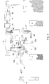
Figure 1 is a diagrammatical view in plan of a plant according to the present invention, -
Figure 2 is a diagrammatical view in longitudinal cross-section of a storage container of the plant inFigure 1 , -
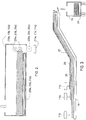
Figure 3 is a diagrammatical view of a longitudinal cross-section of the continuous conveyor of the plant inFigure 1 . - As illustrated in
Figure 1 , in a preferred embodiment the plant according to the present invention comprises a first zone (1) for storage of the dry fraction of the MSW, a second zone (2) for the storage of a thermoplastic polymer material, and a third zone (3) for the storage of an elastomeric polymer material. - In the preferred embodiment illustrated in
Figures 1-3 , a thermoplastic polymer material, mainly consisting of material obtained from the shredding of disposable chlorine-free plastics materials originating from separate collection (PLA) and an elastomeric material mainly consisting of material obtained from the shredding of vulcanised rubber articles, in particular waste tyres, after separation of the metal and/or textile reinforcing members, (WT), reach the plant ready to be metered and fed to a continuous conveyor (18). - The dry fraction of the MSW may be obtained by removing the wet fraction (essentially consisting of putrescible organic components, such as plant waste, food waste, etc.) from the raw MSW using purely mechanical processes (for example shredding and subsequent screening), as described for example in the already mentioned patent
application EP-A-0 930 353 . Subsequently the dry fraction of the MSW may be further shredded and, if necessary, dried to obtain a water content not higher than 15% by weight, preferably not higher than 10% by weight. - As an alternative the dry fraction of the MSW may be obtained in accordance with the known art by subjecting the MSW to a process of biostabilisation, and subsequently to a process of removal of the fine fraction (by screening, for example). The biostabilisation process is a process of biological degradation, in general through microorganisms acting under anaerobic conditions (biooxidation) under controlled temperature and humidity conditions (see for example F. Adani et al., Waste Management and Research, ). At the end of this process the organic fraction which has been transformed by the microorganisms is removed by screening as a fine fraction, that is as a fraction having average dimensions which are generally less than 80 mm, preferably less than 60 mm. The dry fraction so obtained in general has a low moisture content, not more than 15% by weight, preferably not more than 10% by weight, as a result of which a subsequent drying process is not required.
- The particle size of the dry fraction of the MSW obtained according to the methods described above is generally further reduced by shredding in order to achieve dimensions not exceeding 25 mm for at least 90% by weight of the material.
- The dry fraction of the MSW generally comprises paper and its derivatives (cardboard, multi-ply materials), wood, fabrics, leather and wastes from other fractions of materials.
- In case the dry fraction of the MSW reaches the plant at an intermediate processing stage, a unit is provided in the plant according to the invention for its processing, which may comprise a first magnetic separator (5a), a conveyor belt for manual sorting (6), a second magnetic separator (5b) and a drier (9).
- In greater detail, in the embodiment in
Figure 1 the dry fraction of the MSW is discharged to the appropriate storage area (1) from motor vehicles. A mechanical rubber-coated loader (not illustrated) picks up the dry fraction of the MSW from the storage area (1) and discharges it into a hopper lying above a feed conveyor (4). The dry fraction of the MSW is subjected to a first sorting with a magnetic separator (5a) in order to remove any ferrous materials. Subsequently the dry fraction may possibly be caused to pass on a sorting conveyor belt (6) where a manual sorting may be performed to remove any undesirable wastes, such as for example stones or other inert materials which might accidentally be present in the MSW which could damage the equipment used in the subsequent stages. A further sorting using a magnetic separator (5b) may remove any residual ferrous materials. - A conveyor belt (8a) then carries the MSW to a shredding device (7), preferably comprising two shredders in series.
- When the residual moisture content of the dry fraction of the MSW is not greater than a predetermined value, and in particular is not greater than 15% by weight, this is delivered directly to the storage container (10a) by means of a conveyor belt (8b).
- However, when the residual moisture content of the dry fraction of the MSW is greater than that predetermined value it is delivered to a drier (9) via a conveyor belt (8c). The drier generally operates on hot air at a temperature of between 60°C and 80°C, obtained for example by heating ambient air with a methane burner. The drier (9) also comprises a blower system to remove the exiting moist air. Once the desired moisture content has been reached, the dry fraction of the MSW is delivered to the storage container (10a) by means of a conveyor (8d).
- The storage container (10a), which is closed at the top, is provided with a walking floor (23a) and containing sides. A system of rotating paddles (21 a) to move the dry fraction of the MSW before delivering it to the metering screw (22a) and subsequently to a weighing system (11 a) (for example a weighing belt or a load cell, or other known system) is installed close to the discharge head. Advantageously the metering screw has a rate of advance which is regulated in relation to the quantity of each component weighed by the corresponding weighing system. In this way a substantially constant composition of the RDSF is obtained.
- The characteristics of the dry fraction of the MSW stored in the storage container (10a) are preferably the following:
- Residual moisture content: not greater than 15% by weight - Dimensions of at least 90% by weight of the particles: not larger than 25 mm - Average net calorific value (NCV): not less than 3,500 Kcal/kg - Bulk density: 0.10-0.20 g/cm3 - The thermoplastic polymer material mainly comprises material obtained from the shredding of chlorine-free waste plastics materials (PLA) originating from separate collection, such as for example polyethylene terephthalate (PET), polypropylene (PP), polyethylene (PE) and polystyrene (PS).
- According to the embodiment of the plant according to the invention illustrated in
Figures 1-3 , the shredded PLA is taken from the storage zone (2) by a mechanical loader and discharged into the loading hopper (12). From there a conveyor (8e), for example a chain conveyor, carries it to the storage container (10b), which has a structure similar to that of the container (10a) previously illustrated. The storage container (10b) is provided with a walking floor (23b) and containing sides. A system of rotating paddles (21 b) for moving the shredded PLA before delivering it to the metering screw (22b) (Figure 2 ) and subsequently to a weighing system (11b) is installed close to the discharge head. - The characteristics of the shredded PLA stored in the storage container (10b) are preferably as follows:
- Dimension of at least 90% by weight of the particles: not larger than 25 mm - Average net calorific value (NCV): not less than 7,000 Kcal/kg - Bulk density: 0.10-0.15 g/cm3. - The elastomeric polymer material mainly comprises material obtained from the shredding of vulcanised rubber articles, in particular waste tyres (WT), after separation of the metal and/or textile reinforcing members.
- In the embodiment of the plant according to the invention illustrated in
Figures 1-3 , the VVT are taken from the storage area (3) and charged into the storage container (10c), which has a structure similar to that of the storage containers (10a, 10b) previously illustrated. Storage container (10c) is generally provided with a walking floor (23c) and containing sides. A system of rotating paddles (21 c) to move the shredded WT before delivering it to the metering screw (22c) (Figure 2 ) and subsequently to a weighing system (11 c) is installed close to the discharge head. - The characteristics of the shredded WT stored in the storage container (10c) are preferably as follows:
- Dimensions of at least 90% by weight of the particles: not larger than 25 mm - Average net calorific value (NCV): not less than 7,000 Kcal/kg - Bulk density: 0.40-0.70 g/cm3 - Once weighed the three materials pass onto a continuous conveyor (18), for example a conveyor belt or a chain conveyor. The advancing rate in the metering screws (22a, 22b and 22c) of the three components of the RDSF is controlled in relation to data obtained from the weighing systems (11 a, 11 b, 11 c) so as to guarantee a substantially constant composition for the exiting RDSF.
- Transfer of the three components of the RDSF (PLA, dry fraction of MSW and WT) from the corresponding metering screws (22a, 22b, 22c) to the weighing systems (11a, 11 b, 11 c) and subsequently to the continuous conveyor (18) advantageously takes place through gravity.
- As illustrated in
Figure 3 , the continuous conveyor (18) preferably first collects the PLA fraction stored in the container (10b), then the dry fraction of MSW stored in the container (10a) and finally the WT fraction stored in the container (10c), - In the stratification so obtained onto the continuous conveyor (18), the lower layer (25) is formed of the lightest material (PLA), the intermediate layer (26) is formed of the material having an intermediate weight (dry fraction of the MSW) and the upper layer (27) is formed from the heaviest material (WT). In this way the lightest fraction is prevented from dispersing in the environment during the movement of the so stratified materials.
- Finally, the continuous conveyor (18) discharges the collected material into a temporary accumulation container, for example in the articulated trailer (19) of a motor vehicle. The said articulated, trailer (19) is provided with a walking floor (24) for loading and discharging the RDSF.
- As they fall into the box body (19) of the motor vehicle, the three layers (25, 26, 27) of the materials accumulated on the continuous conveyor (18) mix each other.
- Surprisingly it has been observed that this mixing is particularly effective when the lower layer (25) is formed of the lightest material (PLA), the intermediate layer (26) is formed of the material having an intermediate weight (MSW) and the upper layer (27) is formed of the heaviest material (WT).
- The bulk density of the RDSF so obtained is generally less than 0.60 g/cm3, preferably it ranges from 0.35 to 0.12 g/cm3.
- As already mentioned previously, in accordance with one embodiment of the invention the RDSF so obtained can be subjected to a compaction stage (for example by mechanical compression) so as to provide a compacted RDSF in any form suitable for transport, for example substantially rectangular or cylindrical. The compaction stage may be carried out by any mechanical device suitable for the purpose, for example a press (not shown in the Figures). Compaction is carried out in such a way as to obtain a bulk density for the compacted RDSF which generally lies between 0.50 and 0.95 g/cm3, preferably between 0.60 and 0.90 g/cm3. This makes it possible to reduce the volume of the conveyed material and therefore the transport costs, particularly over long distances.
- In this case, at the time of use the compacted RDSF may be again disaggregated in order to reacquire the physical characteristics (in particular the bulk density values indicated above) which render it particularly suitable for combustion processes with suspension burners, and in particular co-combustion processes with fossil fuels, such as those disclosed in the already cited
patent application EP-A-0 953 628 . With this aim at least one mechanical device capable of disaggregating the compacted RDSF, for example a shredder, is provided close to the combustion plant. - The plant in
figure 1 is preferably provided with a control system (not illustrated) which is capable of automating the various stages of treatment and of communicating, suitably through video terminals, with the operators operating the plant. - This control system essentially comprises a programmable control unit (PCU).
- The control system offers the following main control choices:
- settings for the flows of the various materials delivered to the motor vehicle loading unit,
- selection of the three lines which will be subjected to processing,
- management of the operating cycles,
- monitoring of the condition of the process machines served,
- diagnosis of alarms in the machines served.
- Automatic starting of the system will bring about starting of all the machines forming part of the selected systems in sequence. The starting sequence is structured on the basis of first starting the last machine in the selected lines (tail) and then moving backwards starting up all the others in succession until the machines at the head of the lines (moving floor feeders) are started. This makes it possible to prevent the loaded material from accumulating in machines which are still stopped, clogging them. Vice versa, on the same principle, stopping of the system causes the machines to stop in succession away from the head.
- A typical composition of a solid fuel deriving from wastes (RDSF) produced according to this invention is as follows:
- 40-90% by weight, preferably 60-80% by weight, of a dry fraction of MSW,
- 10-60% by weight, preferably 20-40% by weight, of at least one polymer material selected from elastomeric material and thermoplastic material, or mixtures thereof.
- Even more preferably, the solid fuel deriving from wastes (RDSF) produced according to this invention has the following composition:
- 40-90% by weight, preferably 60-80% by weight, of a dry fraction of MSW,
- 5-55% by weight, preferably 10-30% by weight, of at least one elastomeric polymer material,
- 5-55% by weight, preferably 10-30% by weight, of at least one thermoplastic polymer material.
- The bulk density of the RDSF delivered to a combustion plant is generally less than 0.60 g/cm3, preferably ranging from 0.35 to 0.12 g/cm3.
- The RDSF obtained according to this invention may comprise the primary fuel of a combustion plant, or it may be used as a secondary fuel in co-combustion plants, as illustrated in the already cited patent
application EP-A-0 953 628 in which the primary fuel comprises a fossil fuel, for example powdered coal, methane gas or fuel oil. - The combustion plant may be of any type, for example a thermal plant for the generation of heat, a thermoelectric plant for the generation of electrical power, a plant for the manufacture of cement, and the like.
Claims (29)
- A process for producing a refuse derived solid fuel (RDSF) and feeding the said fuel to a combustion plant, which comprises:- providing a first component consisting of a dry fraction of solid urban waste (MSW) in a shredded form,- providing at least one second component in a shredded form selected from an elastomeric material and a thermoplastic material, or mixtures thereof,- separately metering and feeding the said first component and the said at least one second component onto a continuous conveyor in such a way so as to form overlapping layers of the said components,- discharging the said components so assembled into at least one temporary accumulation container so as to form the RDSF,- feeding and metering the RDSF so obtained to a combustion plant.
- Process according to Claim 1, wherein the thermoplastic polymer material mainly comprises a material obtained from the shredding of chlorine-free waste plastics materials.
- Process according to Claim 2, wherein at least 90% of the weight of thermoplastic material has an average particle dimension not exceeding 25 mm.
- Process according to any one of the preceding Claims, wherein the elastomeric polymer material mainly consists of a material obtained from the shredding of waste tyres after separation of the metal and/or textile reinforcing members.
- Process according to Claim 4, wherein at least 90% by weight of the elastomeric material has an average particle dimension not exceeding 25 mm.
- Process according to any one of the preceding Claims, wherein the dry fraction of the MSW is obtained from an unprocessed MSW by mechanical separation of putrescible organic fraction, separation of metal materials, shredding and possibly drying.
- Process according to any one of Claims from 1 to 5, wherein the dry fraction of MSW is obtained by subjecting a raw MSW to a process of biostabilisation and subsequently a process of removing a fine fraction.
- Process according to Claim 7, wherein the removed fine fraction has a dimension of less than 80 mm.
- Process according to any one of the preceding Claims, wherein at least 90% by weight of the dry fraction of MSW has an average particle dimension not exceeding 25 mm.
- Process according to any one of the preceding Claims, wherein the dry fraction of MSW has a moisture content not exceeding 15% by weight.
- Process according to Claim 10, wherein the dry fraction of MSW has a moisture content not exceeding 10% by weight.
- Process according to any one of the preceding Claims, wherein the produced RDSF is subjected to a stage of compaction, transported to the combustion plant and then subjected to a disaggregation stage before the stage of feeding it to the combustion plant.
- Process according to Claim 12, wherein the compacting stage is carried out so as to obtain a compacted RDSF with a bulk density ranging from 0.50 to 0.95 g/cm3.
- Process according to Claim 13, wherein the compacting stage is carried out in such a way so as to obtain a compacted RDSF with a bulk density of from 0.60 to 0.90 g/cm3.
- Process according to any one of the preceding Claims, wherein the stage of metering and feeding the said first component and the said at least one second component onto a continuous conveyor takes place separately, each through at least one metering screw and subsequently a weighing system.
- Process according to Claim 15, wherein the said at least one metering screw has an advancing rate regulated in relation to the quantity of each component weighed by the corresponding weighing system.
- Process according to any one of the preceding Claims, wherein the continuous conveyor collects the various components in the form of successive overlapping layers having a bulk density which increases from the bottom towards the top.
- Process according to Claim 17, wherein a lower layer consisting of the thermoplastic material, an intermediate layer consisting of the dry fraction of the MSW, and an upper layer consisiting of the elastomeric material is formed on the continuous conveyor belt.
- Process according to any one of the preceding claims, wherein the obtained RDSF has the following composition:40-90% by weight of the dry fraction of the RDSF,10-60% by weight of at least one polymer material selected from elastomeric material and thermoplastic material, or mixtures thereof.
- Process according to Claim 19, wherein the obtained RDSF has the following composition:60-80% by weight of the dry fraction of MSW,20-40% by weight of at least one polymer material selected from elastomeric material and thermoplastic material, or mixtures thereof.
- Process according to Claim 19 or 20, wherein the obtained RDSF has the following composition:40-90% by weight of dry fraction of RDSF,5-55% by weight of at least one elastomeric polymer material,5-55% by weight of at least one thermoplastic polymer material.
- Process according to Claim 21, wherein the obtained RDSF has the following composition:60-80% by weight of the dry fraction of the MSW,10-30% by weight of at least one elastomeric polymer material,10-30% by weight of at least one thermoplastic polymer material.
- Process according to any one of the preceding claims, wherein the obtained RDSF has a bulk density of less than 0.60 g/cm3.
- Process according to Claim 23, wherein the RDSF obtained has a bulk density of from 0.35 to 0.12 g/cm3.
- Plant for producing a refuse derived solid fuel, comprising:a shredding device for a first component consisting of a dry fraction of solid urban waste (MSW),at least one storage container for said first component consisting of a dry fraction of solid urban waste (MSW) in a shredded form, at least one metering and feeding device for the said first component,at least one storage container for at least one second component in a shredded form selected from an elastomeric material and a thermoplastic material,at least one metering and feeding device for the said at least one second component,at least one continuous conveyor onto which the said components are fed separately by the said feeding and metering devices so as to form overlapping layers of the said components,at least one temporary accumulation container into which the said components are discharged by the said at least one continuous conveyor.
- Plant according to Claim 25, also comprising at least one storage container for at least one third component in a shredded form also selected from an elastomeric material and a thermoplastic material, different from the second component,
at least one metering and feeding device for the said at least one third component. - Plant according to either of Claims 25 and 26, wherein the said metering and feeding devices comprise at least one metering screw and a weighing system.
- Plant according to Claim 27, wherein the said at least one metering screw has a advancing rate which is regulated in relation to the quantity of each component weighed by the corresponding weighing system.
- Plant according to any one of Claims 25 to 28, also comprising a device for compaction of the obtained RDSF.
Applications Claiming Priority (1)
| Application Number | Priority Date | Filing Date | Title |
|---|---|---|---|
| PCT/IT2004/000154 WO2005093019A1 (en) | 2004-03-29 | 2004-03-29 | Process and plant for producing a refuse derived solid fuel |
Publications (2)
| Publication Number | Publication Date |
|---|---|
| EP1730255A1 EP1730255A1 (en) | 2006-12-13 |
| EP1730255B1 true EP1730255B1 (en) | 2017-05-10 |
Family
ID=34957521
Family Applications (1)
| Application Number | Title | Priority Date | Filing Date |
|---|---|---|---|
| EP04724112.0A Expired - Lifetime EP1730255B1 (en) | 2004-03-29 | 2004-03-29 | Process and plant for producing a refuse derived solid fuel |
Country Status (8)
| Country | Link |
|---|---|
| US (1) | US8091492B2 (en) |
| EP (1) | EP1730255B1 (en) |
| CN (1) | CN1938405B (en) |
| AU (1) | AU2004317574B2 (en) |
| BR (1) | BRPI0418689B1 (en) |
| CA (1) | CA2561236C (en) |
| RS (1) | RS20060539A (en) |
| WO (1) | WO2005093019A1 (en) |
Families Citing this family (8)
| Publication number | Priority date | Publication date | Assignee | Title |
|---|---|---|---|---|
| ES2277782B1 (en) * | 2005-12-21 | 2008-06-01 | Reciclados Vicente Mallen, S.L. | USE AS FUEL OF BRIQUETTES AND / OR GRANULATES ELABORATED FROM WASTE. |
| DE102009007783B3 (en) * | 2009-02-06 | 2010-08-26 | Karlsruher Institut für Technologie | Method for reducing the pollutant potential in exhaust gases and residues of incinerators |
| IT1395382B1 (en) * | 2009-09-09 | 2012-09-14 | Eni Spa | PROCEDURE FOR THE PRODUCTION OF BIO-OIL FROM URBAN SOLID WASTE |
| EA024841B9 (en) * | 2010-07-14 | 2017-01-30 | Ю.Би.Кью. МАТИРИАЛС ЛТД. | Composite material from waste and vulcanized rubber and process for producing same |
| US11046839B2 (en) | 2010-07-14 | 2021-06-29 | Ubq Materials Ltd. | Plastic compositions |
| US9262870B2 (en) | 2010-10-28 | 2016-02-16 | Intralot S.A.—Integrated Lottery Systems and Services | Methods and a system for dispensing |
| US20220315724A1 (en) * | 2019-05-13 | 2022-10-06 | I.Blu S.R.L. | Process of production of a polymer product |
| CN111649335B (en) * | 2020-06-13 | 2023-03-28 | 宁波世茂能源股份有限公司 | Waste incineration power generation system and process |
Family Cites Families (11)
| Publication number | Priority date | Publication date | Assignee | Title |
|---|---|---|---|---|
| US1772285A (en) * | 1927-03-14 | 1930-08-05 | Paul S Knittel | Method and apparatus for disposing of refuse |
| DE1801533A1 (en) * | 1968-10-05 | 1970-05-27 | Schnitzler Dr Ing Erwin F | Device for the continuous production of a fleece from chips, fibers and the like. |
| US4314887A (en) * | 1978-06-19 | 1982-02-09 | Peabody Coal Company, Inc. | Apparatus for producing coke from fine and coarse coal |
| NL8701601A (en) * | 1987-07-08 | 1989-02-01 | Mosa Koninkl Bv | FLOOR TILE SET, METHOD FOR PRODUCING A FLOOR TILE FOR THE SET AND APPARATUS FOR CARRYING OUT THE METHOD |
| DE4126838C2 (en) | 1991-08-14 | 1994-06-09 | Hoelter Heinz | Waste disposal procedures |
| RO111101B (en) | 1994-03-29 | 1996-06-28 | Jesus Hernandez Del Cast Maria | Preparation process for a solid fuel which is made of solid combustible fuels with low value |
| IT1297030B1 (en) | 1997-12-30 | 1999-08-03 | Pirelli Ambiente S P A | SOLID COMBUSTIBLE COMPOSITION |
| US6375691B1 (en) * | 1998-04-30 | 2002-04-23 | Pirelli Ambiente S.P.A. | Fuel composition which combusts instantaneously, method and plant therefor |
| EP0953628B1 (en) | 1998-04-30 | 2006-04-05 | Pirelli & C Ambiente S.p.A. | Fuel composition which combusts instantaneously and method for combustion |
| DE10224133A1 (en) * | 2001-08-22 | 2003-03-06 | Emschergenossenschaft Lippever | Process for treating sludge |
| RU2253668C1 (en) | 2003-11-12 | 2005-06-10 | Хрусталёв Евгений Николаевич | Method of reworking garbage of town dumps and device for realization of this method |
-
2004
- 2004-03-29 RS YUP20060539 patent/RS20060539A/en unknown
- 2004-03-29 EP EP04724112.0A patent/EP1730255B1/en not_active Expired - Lifetime
- 2004-03-29 BR BRPI0418689-3B1A patent/BRPI0418689B1/en not_active IP Right Cessation
- 2004-03-29 CA CA 2561236 patent/CA2561236C/en not_active Expired - Fee Related
- 2004-03-29 US US10/594,269 patent/US8091492B2/en not_active Expired - Fee Related
- 2004-03-29 AU AU2004317574A patent/AU2004317574B2/en not_active Ceased
- 2004-03-29 CN CN2004800426225A patent/CN1938405B/en not_active Expired - Fee Related
- 2004-03-29 WO PCT/IT2004/000154 patent/WO2005093019A1/en active Application Filing
Non-Patent Citations (1)
| Title |
|---|
| None * |
Also Published As
| Publication number | Publication date |
|---|---|
| US8091492B2 (en) | 2012-01-10 |
| AU2004317574A1 (en) | 2005-10-06 |
| RS20060539A (en) | 2008-09-29 |
| CN1938405B (en) | 2010-12-08 |
| BRPI0418689B1 (en) | 2014-02-18 |
| US20070283861A1 (en) | 2007-12-13 |
| CN1938405A (en) | 2007-03-28 |
| WO2005093019A1 (en) | 2005-10-06 |
| CA2561236A1 (en) | 2005-10-06 |
| AU2004317574B2 (en) | 2010-08-12 |
| BRPI0418689A (en) | 2007-06-12 |
| CA2561236C (en) | 2012-09-25 |
| EP1730255A1 (en) | 2006-12-13 |
Similar Documents
| Publication | Publication Date | Title |
|---|---|---|
| US7252691B2 (en) | Conversion of municipal solid waste to high fuel value | |
| US20180015515A1 (en) | A novel method and an apparatus in converting unsorted municipal solid waste into geo-polymer pellets/briquettes and geo-polymer bricks/paver blocks | |
| US6165238A (en) | Fuel pellet and method for its production | |
| CA2282508A1 (en) | Refuse-treatment method | |
| EP1730255B1 (en) | Process and plant for producing a refuse derived solid fuel | |
| JP2002356689A (en) | Fuel blend and fuel supplying method | |
| GB2466215A (en) | Wet recyclable material processing | |
| JP6785017B1 (en) | Method for constructing valuable resource production system derived from mushroom waste medium and valuable resource production system derived from mushroom waste medium | |
| RU99778U1 (en) | TECHNOLOGICAL COMPLEX FOR PRODUCTION OF PEAT | |
| RU2334786C2 (en) | Method and system for solid fuel recycled generation | |
| CN115431431A (en) | Plastic filling compound/combined regenerated coarse grain and its production method | |
| ZA200607738B (en) | Process and plant for producing a refuse derived solid fuel | |
| KR19990068789A (en) | Method and system of producing organic fertlizer with sludge and sawdust | |
| US3622002A (en) | Plant for processing of refuse material | |
| WO2002051969A1 (en) | Fuel pellet and method for its production | |
| CN219580714U (en) | Biomass fuel raw material circulating and crushing system | |
| KR101535628B1 (en) | A solid fuel using a mix waste and a preparation method thereof | |
| JP4302053B2 (en) | Combustion method | |
| JP2510128B2 (en) | Sawdust Recycling Processing Device and Sawdust Recycling Processing Method | |
| CA3155566A1 (en) | Treatment plant with optimised densimetric sorting and related treatment process | |
| CZ147697A3 (en) | Biological waste treatment plant | |
| WO2004110634A1 (en) | Method and installation for processing waste | |
| PT11138T (en) | AGREEMENT PROCESS OF VARIOUS TYPES OF WASTE WITH A DESTINATION | |
| IES20080986A2 (en) | Wet recyclable material processing | |
| KR20030088678A (en) | Sharing and fixed quantity suppling structure |
Legal Events
| Date | Code | Title | Description |
|---|---|---|---|
| PUAI | Public reference made under article 153(3) epc to a published international application that has entered the european phase |
Free format text: ORIGINAL CODE: 0009012 |
|
| 17P | Request for examination filed |
Effective date: 20060929 |
|
| AK | Designated contracting states |
Kind code of ref document: A1 Designated state(s): AT BE BG CH CY CZ DE DK EE ES FI FR GB GR HU IE IT LI LU MC NL PL PT RO SE SI SK TR |
|
| 17Q | First examination report despatched |
Effective date: 20070601 |
|
| DAX | Request for extension of the european patent (deleted) | ||
| RAP1 | Party data changed (applicant data changed or rights of an application transferred) |
Owner name: PIRELLI & C. AMBIENTE S.P.A. |
|
| RAP1 | Party data changed (applicant data changed or rights of an application transferred) |
Owner name: PIRELLI & C. AMBIENTE S.R.L. |
|
| GRAP | Despatch of communication of intention to grant a patent |
Free format text: ORIGINAL CODE: EPIDOSNIGR1 |
|
| GRAJ | Information related to disapproval of communication of intention to grant by the applicant or resumption of examination proceedings by the epo deleted |
Free format text: ORIGINAL CODE: EPIDOSDIGR1 |
|
| GRAP | Despatch of communication of intention to grant a patent |
Free format text: ORIGINAL CODE: EPIDOSNIGR1 |
|
| INTG | Intention to grant announced |
Effective date: 20161024 |
|
| INTG | Intention to grant announced |
Effective date: 20161117 |
|
| GRAS | Grant fee paid |
Free format text: ORIGINAL CODE: EPIDOSNIGR3 |
|
| GRAJ | Information related to disapproval of communication of intention to grant by the applicant or resumption of examination proceedings by the epo deleted |
Free format text: ORIGINAL CODE: EPIDOSDIGR1 |
|
| GRAL | Information related to payment of fee for publishing/printing deleted |
Free format text: ORIGINAL CODE: EPIDOSDIGR3 |
|
| GRAR | Information related to intention to grant a patent recorded |
Free format text: ORIGINAL CODE: EPIDOSNIGR71 |
|
| INTC | Intention to grant announced (deleted) | ||
| GRAA | (expected) grant |
Free format text: ORIGINAL CODE: 0009210 |
|
| INTG | Intention to grant announced |
Effective date: 20170315 |
|
| AK | Designated contracting states |
Kind code of ref document: B1 Designated state(s): AT BE BG CH CY CZ DE DK EE ES FI FR GB GR HU IE IT LI LU MC NL PL PT RO SE SI SK TR |
|
| REG | Reference to a national code |
Ref country code: GB Ref legal event code: FG4D |
|
| REG | Reference to a national code |
Ref country code: AT Ref legal event code: REF Ref document number: 892331 Country of ref document: AT Kind code of ref document: T Effective date: 20170515 Ref country code: CH Ref legal event code: EP |
|
| REG | Reference to a national code |
Ref country code: IE Ref legal event code: FG4D |
|
| REG | Reference to a national code |
Ref country code: DE Ref legal event code: R096 Ref document number: 602004051233 Country of ref document: DE |
|
| REG | Reference to a national code |
Ref country code: NL Ref legal event code: MP Effective date: 20170510 |
|
| REG | Reference to a national code |
Ref country code: AT Ref legal event code: MK05 Ref document number: 892331 Country of ref document: AT Kind code of ref document: T Effective date: 20170510 |
|
| PG25 | Lapsed in a contracting state [announced via postgrant information from national office to epo] |
Ref country code: GR Free format text: LAPSE BECAUSE OF FAILURE TO SUBMIT A TRANSLATION OF THE DESCRIPTION OR TO PAY THE FEE WITHIN THE PRESCRIBED TIME-LIMIT Effective date: 20170811 Ref country code: ES Free format text: LAPSE BECAUSE OF FAILURE TO SUBMIT A TRANSLATION OF THE DESCRIPTION OR TO PAY THE FEE WITHIN THE PRESCRIBED TIME-LIMIT Effective date: 20170510 Ref country code: FI Free format text: LAPSE BECAUSE OF FAILURE TO SUBMIT A TRANSLATION OF THE DESCRIPTION OR TO PAY THE FEE WITHIN THE PRESCRIBED TIME-LIMIT Effective date: 20170510 Ref country code: AT Free format text: LAPSE BECAUSE OF FAILURE TO SUBMIT A TRANSLATION OF THE DESCRIPTION OR TO PAY THE FEE WITHIN THE PRESCRIBED TIME-LIMIT Effective date: 20170510 |
|
| PG25 | Lapsed in a contracting state [announced via postgrant information from national office to epo] |
Ref country code: SE Free format text: LAPSE BECAUSE OF FAILURE TO SUBMIT A TRANSLATION OF THE DESCRIPTION OR TO PAY THE FEE WITHIN THE PRESCRIBED TIME-LIMIT Effective date: 20170510 Ref country code: NL Free format text: LAPSE BECAUSE OF FAILURE TO SUBMIT A TRANSLATION OF THE DESCRIPTION OR TO PAY THE FEE WITHIN THE PRESCRIBED TIME-LIMIT Effective date: 20170510 Ref country code: BG Free format text: LAPSE BECAUSE OF FAILURE TO SUBMIT A TRANSLATION OF THE DESCRIPTION OR TO PAY THE FEE WITHIN THE PRESCRIBED TIME-LIMIT Effective date: 20170810 Ref country code: PL Free format text: LAPSE BECAUSE OF FAILURE TO SUBMIT A TRANSLATION OF THE DESCRIPTION OR TO PAY THE FEE WITHIN THE PRESCRIBED TIME-LIMIT Effective date: 20170510 |
|
| PG25 | Lapsed in a contracting state [announced via postgrant information from national office to epo] |
Ref country code: CZ Free format text: LAPSE BECAUSE OF FAILURE TO SUBMIT A TRANSLATION OF THE DESCRIPTION OR TO PAY THE FEE WITHIN THE PRESCRIBED TIME-LIMIT Effective date: 20170510 Ref country code: RO Free format text: LAPSE BECAUSE OF FAILURE TO SUBMIT A TRANSLATION OF THE DESCRIPTION OR TO PAY THE FEE WITHIN THE PRESCRIBED TIME-LIMIT Effective date: 20170510 Ref country code: SK Free format text: LAPSE BECAUSE OF FAILURE TO SUBMIT A TRANSLATION OF THE DESCRIPTION OR TO PAY THE FEE WITHIN THE PRESCRIBED TIME-LIMIT Effective date: 20170510 Ref country code: EE Free format text: LAPSE BECAUSE OF FAILURE TO SUBMIT A TRANSLATION OF THE DESCRIPTION OR TO PAY THE FEE WITHIN THE PRESCRIBED TIME-LIMIT Effective date: 20170510 Ref country code: DK Free format text: LAPSE BECAUSE OF FAILURE TO SUBMIT A TRANSLATION OF THE DESCRIPTION OR TO PAY THE FEE WITHIN THE PRESCRIBED TIME-LIMIT Effective date: 20170510 |
|
| REG | Reference to a national code |
Ref country code: DE Ref legal event code: R097 Ref document number: 602004051233 Country of ref document: DE |
|
| PLBE | No opposition filed within time limit |
Free format text: ORIGINAL CODE: 0009261 |
|
| STAA | Information on the status of an ep patent application or granted ep patent |
Free format text: STATUS: NO OPPOSITION FILED WITHIN TIME LIMIT |
|
| 26N | No opposition filed |
Effective date: 20180213 |
|
| PG25 | Lapsed in a contracting state [announced via postgrant information from national office to epo] |
Ref country code: SI Free format text: LAPSE BECAUSE OF FAILURE TO SUBMIT A TRANSLATION OF THE DESCRIPTION OR TO PAY THE FEE WITHIN THE PRESCRIBED TIME-LIMIT Effective date: 20170510 |
|
| REG | Reference to a national code |
Ref country code: DE Ref legal event code: R119 Ref document number: 602004051233 Country of ref document: DE |
|
| REG | Reference to a national code |
Ref country code: CH Ref legal event code: PL |
|
| GBPC | Gb: european patent ceased through non-payment of renewal fee |
Effective date: 20180329 |
|
| PG25 | Lapsed in a contracting state [announced via postgrant information from national office to epo] |
Ref country code: MC Free format text: LAPSE BECAUSE OF FAILURE TO SUBMIT A TRANSLATION OF THE DESCRIPTION OR TO PAY THE FEE WITHIN THE PRESCRIBED TIME-LIMIT Effective date: 20170510 |
|
| REG | Reference to a national code |
Ref country code: BE Ref legal event code: MM Effective date: 20180331 |
|
| REG | Reference to a national code |
Ref country code: IE Ref legal event code: MM4A |
|
| PG25 | Lapsed in a contracting state [announced via postgrant information from national office to epo] |
Ref country code: LU Free format text: LAPSE BECAUSE OF NON-PAYMENT OF DUE FEES Effective date: 20180329 |
|
| PG25 | Lapsed in a contracting state [announced via postgrant information from national office to epo] |
Ref country code: IE Free format text: LAPSE BECAUSE OF NON-PAYMENT OF DUE FEES Effective date: 20180329 Ref country code: DE Free format text: LAPSE BECAUSE OF NON-PAYMENT OF DUE FEES Effective date: 20181002 |
|
| PG25 | Lapsed in a contracting state [announced via postgrant information from national office to epo] |
Ref country code: CH Free format text: LAPSE BECAUSE OF NON-PAYMENT OF DUE FEES Effective date: 20180331 Ref country code: BE Free format text: LAPSE BECAUSE OF NON-PAYMENT OF DUE FEES Effective date: 20180331 Ref country code: GB Free format text: LAPSE BECAUSE OF NON-PAYMENT OF DUE FEES Effective date: 20180329 Ref country code: LI Free format text: LAPSE BECAUSE OF NON-PAYMENT OF DUE FEES Effective date: 20180331 |
|
| PG25 | Lapsed in a contracting state [announced via postgrant information from national office to epo] |
Ref country code: FR Free format text: LAPSE BECAUSE OF NON-PAYMENT OF DUE FEES Effective date: 20180331 |
|
| PG25 | Lapsed in a contracting state [announced via postgrant information from national office to epo] |
Ref country code: TR Free format text: LAPSE BECAUSE OF FAILURE TO SUBMIT A TRANSLATION OF THE DESCRIPTION OR TO PAY THE FEE WITHIN THE PRESCRIBED TIME-LIMIT Effective date: 20170510 |
|
| PG25 | Lapsed in a contracting state [announced via postgrant information from national office to epo] |
Ref country code: PT Free format text: LAPSE BECAUSE OF FAILURE TO SUBMIT A TRANSLATION OF THE DESCRIPTION OR TO PAY THE FEE WITHIN THE PRESCRIBED TIME-LIMIT Effective date: 20170510 Ref country code: HU Free format text: LAPSE BECAUSE OF FAILURE TO SUBMIT A TRANSLATION OF THE DESCRIPTION OR TO PAY THE FEE WITHIN THE PRESCRIBED TIME-LIMIT; INVALID AB INITIO Effective date: 20040329 |
|
| PG25 | Lapsed in a contracting state [announced via postgrant information from national office to epo] |
Ref country code: CY Free format text: LAPSE BECAUSE OF FAILURE TO SUBMIT A TRANSLATION OF THE DESCRIPTION OR TO PAY THE FEE WITHIN THE PRESCRIBED TIME-LIMIT Effective date: 20170510 |
|
| PGFP | Annual fee paid to national office [announced via postgrant information from national office to epo] |
Ref country code: IT Payment date: 20230321 Year of fee payment: 20 |