EP1729508A2 - Kameramodul - Google Patents
Kameramodul Download PDFInfo
- Publication number
- EP1729508A2 EP1729508A2 EP06114157A EP06114157A EP1729508A2 EP 1729508 A2 EP1729508 A2 EP 1729508A2 EP 06114157 A EP06114157 A EP 06114157A EP 06114157 A EP06114157 A EP 06114157A EP 1729508 A2 EP1729508 A2 EP 1729508A2
- Authority
- EP
- European Patent Office
- Prior art keywords
- camera module
- housing
- magnetic
- module according
- opening
- Prior art date
- Legal status (The legal status is an assumption and is not a legal conclusion. Google has not performed a legal analysis and makes no representation as to the accuracy of the status listed.)
- Withdrawn
Links
Images


Classifications
-
- H—ELECTRICITY
- H04—ELECTRIC COMMUNICATION TECHNIQUE
- H04N—PICTORIAL COMMUNICATION, e.g. TELEVISION
- H04N23/00—Cameras or camera modules comprising electronic image sensors; Control thereof
- H04N23/80—Camera processing pipelines; Components thereof
- H04N23/81—Camera processing pipelines; Components thereof for suppressing or minimising disturbance in the image signal generation
- H04N23/811—Camera processing pipelines; Components thereof for suppressing or minimising disturbance in the image signal generation by dust removal, e.g. from surfaces of the image sensor or processing of the image signal output by the electronic image sensor
-
- H—ELECTRICITY
- H04—ELECTRIC COMMUNICATION TECHNIQUE
- H04N—PICTORIAL COMMUNICATION, e.g. TELEVISION
- H04N23/00—Cameras or camera modules comprising electronic image sensors; Control thereof
- H04N23/50—Constructional details
-
- H—ELECTRICITY
- H04—ELECTRIC COMMUNICATION TECHNIQUE
- H04N—PICTORIAL COMMUNICATION, e.g. TELEVISION
- H04N23/00—Cameras or camera modules comprising electronic image sensors; Control thereof
- H04N23/50—Constructional details
- H04N23/51—Housings
Definitions
- the invention relates in general to a camera module, and more particularly to a camera module having a magnetic material.
- camera modules are widely used in digital camera, camera mobile phone and digital video for applying to functions of image fetching, image recording, and image playing.
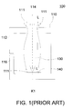
- FIG. 1 is a cross-sectional view of a conventional camera module.
- a conventional open type camera module 100 includes a housing 110, a lens module 130 and a sensor 140.
- the housing 110 includes an upper cover 112, a transparent region 114 and a lower cover 116.
- the transparent region 114 is formed on the upper cover 112, so that the camera module 100 has an opening structure.
- the lens module 130 is disposed in the housing 110, and the sensor 140 is disposed on the lower cover 116. Furthermore, the transparent region 114, the lens module 130 and the sensor 140 are positioned on the same optical axis K1.
- the light L penetrating the transparent region 114 is focused on the sensor 140 via the lens module 130 to generate an image signal. Therefore cleanness of the sensor 140 is crucial to image quality.
- particles 111 such as cast iron filings or metal powders are likely to be generated due to the coupling or friction between the metal parts. Nonetheless, when the camera module 100 is used under normal circumstances, a large volume of particles 111 already exist in the air. As shown in FIG. 1, the particles 111 are easily to enter the camera module 100 through the transparent region 114 and alighted on the surface of the sensor 140. As a result, problems such as white spots, blurred image would occur, reducing the yield rate and the lifespan of the digital camera.
- a housing having a magnetic force or using the magnetic component disposed in the housing attracts the metal particles around the magnetic component or the housing, so that most of the particles are prevented from tarnishing the sensor of the camera module to improve the image quality.
- the yield rate of the camera module is increased, and the lifespan of the camera module is prolonged.
- the embodiment of the invention achieves the above-identified object by providing a camera module including a housing.
- the housing has an opening.
- the housing having a magnetic material disposed in the housing can be used to absorb both the particles surrounding the camera module and the particles entering the housing through the opening.
- the embodiment of the invention achieves the above-identified object by providing a camera module including a housing and a magnetic component.
- the housing has an opening, and the magnetic component is disposed in the housing for absorbing the particles entering the housing through the opening.
- FIG. 1 is a cross-sectional view of a conventional camera module
- FIG. 2 is a cross-sectional view of a camera module according to a first embodiment of the invention
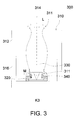
- FIG. 3 is a cross-sectional view of a camera module according to a second embodiment of the invention.
- FIG. 4 is a cross-sectional view of a camera module according to a third embodiment of the invention.
- the camera module 200 includes a housing 210, a magnetic component 220, a lens module 230 and a sensor 240.
- the housing 210 includes an upper cover 212, a lower cover 216 and a transparent region 214.
- the upper cover 212 is coupled to the lower cover 216.
- the transparent region 214 is formed on the upper cover 212.
- the light L enters the camera module 200 through the transparent region 214.
- a magnet in the present embodiment exemplifies the magnetic component 220, which can be an electrified magnetic core or magnetic matter.
- the magnetic component 220 is embedded to be surrounding the transparent region 214.
- the lens module 230 is disposed in the housing 210.
- the sensor 240 is disposed on the lower cover 216. Furthermore, the transparent region 214, the lens module 230 and the sensor 240 are positioned on the same optical axis K2.
- the lens module 230 can move forwards and backwards along the optical axis K2 to focus the incident light L on the sensor 240.
- the open type camera module 200 is exposed in the air, no matter is during the manufacturing process or service, particles in the air are easy to enter the housing 210 through the transparent region 214.
- the magnetic component 220 is embedded to be surrounding the transparent region 214, so that a tight magnetic net M1 is formed surrounding the transparent region 214.
- the metal particles 211 in the air are passing through the magnetic net M1 to enter the transparent region 214, the metal particles 211 are alighted on the surface of the magnetic component 220, lest the metal particles 211 might enter the housing 210 to be alighted on the sensor 240, thereby deteriorating image quality.
- the camera module 300 includes a housing 310, a magnetic component 320, a lens module 330 and a sensor 340.
- the housing 310 includes an upper cover 312, a lower cover 316 and a transparent region 314.
- the camera module 300 of the present embodiment differs the camera module 200 of the first embodiment in that the magnetic component 320 surrounds the peripheral of the sensor 340 and is disposed on the lower cover 316, so the magnetic component 320 can form a tight magnetic net M2 surrounding the sensor 340 and covering atop of the entire the sensor 340.
- the metal particles 311 When entering the housing 310, the metal particles 311 would be alighted on the surface of the magnetic component 320 near the surface of the sensor 340 during the course of passing through the magnet net M2, so that the metal particles 311 are prevented from tarnishing the sensor 340 and that image quality is increased.
- the camera module 200 is exemplified by the magnetic component 220 being embedded to be surrounding the transparent region 214, while the camera module 300 is exemplified by the magnetic component 320 surrounding the peripheral of the sensor 340 to be disposed on the lower cover 316.
- the magnetic component 320 can be disposed surrounding the peripheral of the lens module 330 or disposed in any position on the inner lateral surface of the housing. Any designs capable of forming a magnetic net to effectively absorb the metal particles entering the housing through the transparent region, thereby improving image quality are within the scope of protection of the invention.
- Camera module 400 includes a housing 410 with magnetic material, a lens module 430 and a sensor 440.
- the housing 410 includes an upper cover 412, a lower cover 416 and a transparent region 414.
- the camera module 400 of the present embodiment differs with the camera module 200 (300) of the first embodiment and the second embodiment in that the camera module 400 is without a magnetic component and that the housing 410 has an evenly distributed magnetic material. Other similarities are not repeated here.
- a magnetic powder in the present embodiment exemplifies the magnetic material, which can be any magnetic materials.
- the magnetic material is evenly distributed on the housing 410, so that a magnetic net M3 is formed in the peripheral of the housing 410 and that a magnetic net M4 is formed in the housing 410.
- the metal particles 411 When the metal particles 411 are near the housing 410, the metal particles 411 would be alighted on the surface of the housing 410 and can not enter the housing 410 due to the function of the magnetic net M3.
- the metal particles 411 may enter the housing 410 through the transparent region 414, the metal particles 411 would be alighted on the inner surface of the housing 410 in the course of entering the housing 410 due to the function of the magnetic net M4.
- the metal particles 411 are prevented from the housing 410 but alighted on the sensor 440, so that image quality is increased.
- a magnetic material being evenly distributed on the housing 410 exemplifies the camera module 400 of the invention.
- the magnetic material of invention can be distributed on an area of the housing surrounding the transparent region or evenly distributed on the lower cover or the inner lateral surface of the housing. Any variations that absorb and prevent metal particles from entering the housing through the transparent region by forming a magnetic region so that the metal particles are not alighted on the sensor and that image quality is increased are within the scope of protection of the technology of the invention.
- the invention can be applicable to camera module with any types of opening. Any designs that form a magnetic region to absorb metal particles so as to increase image quality by disposing a magnetic component in the camera module or by using a housing having a magnetic material are within the scope of protection of the invention.
- the camera module disclosed in above embodiments of the invention permits metal particles to be absorbed by the magnetic component or the housing before reaching the sensor, so that most of the particles are prevented from tarnishing the sensor and that image quality is increased.
- the yield rate of the camera module is increased, and the lifespan of the camera module is prolonged.
Landscapes
- Engineering & Computer Science (AREA)
- Multimedia (AREA)
- Signal Processing (AREA)
- Shielding Devices Or Components To Electric Or Magnetic Fields (AREA)
- Studio Devices (AREA)
- Investigating Or Analysing Materials By Optical Means (AREA)
Applications Claiming Priority (1)
| Application Number | Priority Date | Filing Date | Title |
|---|---|---|---|
| CNA2005100754902A CN1874428A (zh) | 2005-06-02 | 2005-06-02 | 光机模块 |
Publications (2)
| Publication Number | Publication Date |
|---|---|
| EP1729508A2 true EP1729508A2 (de) | 2006-12-06 |
| EP1729508A3 EP1729508A3 (de) | 2009-04-22 |
Family
ID=36763270
Family Applications (1)
| Application Number | Title | Priority Date | Filing Date |
|---|---|---|---|
| EP06114157A Withdrawn EP1729508A3 (de) | 2005-06-02 | 2006-05-18 | Kameramodul |
Country Status (2)
| Country | Link |
|---|---|
| EP (1) | EP1729508A3 (de) |
| CN (1) | CN1874428A (de) |
Family Cites Families (6)
| Publication number | Priority date | Publication date | Assignee | Title |
|---|---|---|---|---|
| US4547909A (en) * | 1983-11-17 | 1985-10-22 | Michael Bell | Eye protection means for eye wear |
| JPS62261158A (ja) * | 1986-05-08 | 1987-11-13 | Matsushita Electronics Corp | 固体撮像装置 |
| US7215372B2 (en) * | 2002-05-17 | 2007-05-08 | Olympus Corporation | Optical apparatus having dust off function |
| JP2003283894A (ja) * | 2002-03-22 | 2003-10-03 | Konica Corp | 撮像装置 |
| JP4244624B2 (ja) * | 2002-12-06 | 2009-03-25 | 株式会社ニコン | カメラ |
| AU2003204182A1 (en) * | 2003-04-01 | 2004-10-21 | Damien Charles Bryan | Magnetic Safety Glasses |
-
2005
- 2005-06-02 CN CNA2005100754902A patent/CN1874428A/zh active Pending
-
2006
- 2006-05-18 EP EP06114157A patent/EP1729508A3/de not_active Withdrawn
Also Published As
| Publication number | Publication date |
|---|---|
| EP1729508A3 (de) | 2009-04-22 |
| CN1874428A (zh) | 2006-12-06 |
Similar Documents
| Publication | Publication Date | Title |
|---|---|---|
| CN208174818U (zh) | 相机模块 | |
| CN104423003B (zh) | 相机模块 | |
| KR20130127780A (ko) | 카메라 모듈 | |
| US20130265660A1 (en) | Lens unit and imaging apparatus | |
| JP2007006475A (ja) | 移動通信装置のカメラモジュール | |
| US20140368723A1 (en) | Lens module and camera module including the same | |
| JP2009271405A (ja) | カメラモジュール | |
| CN101419327A (zh) | 壳部件、传感器模块和电子信息设备 | |
| KR101455124B1 (ko) | 촬상 센서 패키지를 구비한 촬상장치 | |
| CN207249315U (zh) | 遮光部件以及镜头组件 | |
| US12061372B2 (en) | Lens driving module | |
| TW202113421A (zh) | 成像鏡頭模組與電子裝置 | |
| KR20130076287A (ko) | 카메라 모듈 | |
| US20060280499A1 (en) | Camera module | |
| CN100573216C (zh) | 透镜镜筒以及图像捕获装置 | |
| KR20080110682A (ko) | 촬상 장치 | |
| EP1739958B1 (de) | Elektronische Vorrichtung und ihr Bildaufnahmemodul | |
| KR101459585B1 (ko) | 렌즈 구동력이 향상된 휴대단말기용 카메라 액추에이터 | |
| CN212302033U (zh) | 镜头驱动模块与电子装置 | |
| JP2006047364A (ja) | シャッタ装置を内蔵したレンズ鏡筒およびこの組立方法 | |
| JP2009098462A (ja) | 固体撮像装置およびこれを搭載する撮像機器、並びに、固体撮像装置の製造方法 | |
| KR100829982B1 (ko) | 카메라 모듈 | |
| KR102270550B1 (ko) | 쉴드 커버 결합구조부 및 이를 포함하는 카메라 모듈 액추에이터 | |
| US20060291853A1 (en) | Electronic device and image capture module thereof | |
| EP1530366A2 (de) | Bildaufnahmevorrichtung und dessen Herstellungsverfahren |
Legal Events
| Date | Code | Title | Description |
|---|---|---|---|
| PUAI | Public reference made under article 153(3) epc to a published international application that has entered the european phase |
Free format text: ORIGINAL CODE: 0009012 |
|
| AK | Designated contracting states |
Kind code of ref document: A2 Designated state(s): AT BE BG CH CY CZ DE DK EE ES FI FR GB GR HU IE IS IT LI LT LU LV MC NL PL PT RO SE SI SK TR |
|
| AX | Request for extension of the european patent |
Extension state: AL BA HR MK YU |
|
| PUAL | Search report despatched |
Free format text: ORIGINAL CODE: 0009013 |
|
| RIC1 | Information provided on ipc code assigned before grant |
Ipc: H04N 5/232 20060101ALI20090312BHEP Ipc: B01D 35/06 20060101ALI20090312BHEP Ipc: H04N 5/225 20060101AFI20060811BHEP |
|
| AK | Designated contracting states |
Kind code of ref document: A3 Designated state(s): AT BE BG CH CY CZ DE DK EE ES FI FR GB GR HU IE IS IT LI LT LU LV MC NL PL PT RO SE SI SK TR |
|
| AX | Request for extension of the european patent |
Extension state: AL BA HR MK YU |
|
| AKX | Designation fees paid | ||
| STAA | Information on the status of an ep patent application or granted ep patent |
Free format text: STATUS: THE APPLICATION IS DEEMED TO BE WITHDRAWN |
|
| 18D | Application deemed to be withdrawn |
Effective date: 20091023 |
|
| REG | Reference to a national code |
Ref country code: DE Ref legal event code: 8566 |