EP1728750A2 - Automatic winder comprising device sticking label to take up tube - Google Patents
Automatic winder comprising device sticking label to take up tube Download PDFInfo
- Publication number
- EP1728750A2 EP1728750A2 EP06112990A EP06112990A EP1728750A2 EP 1728750 A2 EP1728750 A2 EP 1728750A2 EP 06112990 A EP06112990 A EP 06112990A EP 06112990 A EP06112990 A EP 06112990A EP 1728750 A2 EP1728750 A2 EP 1728750A2
- Authority
- EP
- European Patent Office
- Prior art keywords
- label
- tube
- take
- winding
- sticking
- Prior art date
- Legal status (The legal status is an assumption and is not a legal conclusion. Google has not performed a legal analysis and makes no representation as to the accuracy of the status listed.)
- Withdrawn
Links
- 238000004804 winding Methods 0.000 claims abstract description 136
- 230000015572 biosynthetic process Effects 0.000 description 3
- 230000007547 defect Effects 0.000 description 3
- 238000004519 manufacturing process Methods 0.000 description 3
- 239000000853 adhesive Substances 0.000 description 2
- 230000001070 adhesive effect Effects 0.000 description 2
- 238000000034 method Methods 0.000 description 2
- 239000011295 pitch Substances 0.000 description 2
- 238000003825 pressing Methods 0.000 description 2
- 238000009987 spinning Methods 0.000 description 2
- 101000737052 Homo sapiens Coiled-coil domain-containing protein 54 Proteins 0.000 description 1
- 101000824971 Homo sapiens Sperm surface protein Sp17 Proteins 0.000 description 1
- 102100022441 Sperm surface protein Sp17 Human genes 0.000 description 1
- 238000005520 cutting process Methods 0.000 description 1
- 230000002950 deficient Effects 0.000 description 1
- 238000010586 diagram Methods 0.000 description 1
- 238000009434 installation Methods 0.000 description 1
- 238000007378 ring spinning Methods 0.000 description 1
Images


Classifications
-
- B—PERFORMING OPERATIONS; TRANSPORTING
- B65—CONVEYING; PACKING; STORING; HANDLING THIN OR FILAMENTARY MATERIAL
- B65C—LABELLING OR TAGGING MACHINES, APPARATUS, OR PROCESSES
- B65C3/00—Labelling other than flat surfaces
-
- B—PERFORMING OPERATIONS; TRANSPORTING
- B65—CONVEYING; PACKING; STORING; HANDLING THIN OR FILAMENTARY MATERIAL
- B65C—LABELLING OR TAGGING MACHINES, APPARATUS, OR PROCESSES
- B65C9/00—Details of labelling machines or apparatus
- B65C9/08—Label feeding
- B65C9/18—Label feeding from strips, e.g. from rolls
- B65C9/1865—Label feeding from strips, e.g. from rolls the labels adhering on a backing strip
- B65C9/1876—Label feeding from strips, e.g. from rolls the labels adhering on a backing strip and being transferred by suction means
- B65C9/1884—Label feeding from strips, e.g. from rolls the labels adhering on a backing strip and being transferred by suction means the suction means being a movable vacuum arm or pad
-
- B—PERFORMING OPERATIONS; TRANSPORTING
- B65—CONVEYING; PACKING; STORING; HANDLING THIN OR FILAMENTARY MATERIAL
- B65C—LABELLING OR TAGGING MACHINES, APPARATUS, OR PROCESSES
- B65C9/00—Details of labelling machines or apparatus
- B65C9/26—Devices for applying labels
- B65C9/36—Wipers; Pressers
-
- B—PERFORMING OPERATIONS; TRANSPORTING
- B65—CONVEYING; PACKING; STORING; HANDLING THIN OR FILAMENTARY MATERIAL
- B65H—HANDLING THIN OR FILAMENTARY MATERIAL, e.g. SHEETS, WEBS, CABLES
- B65H67/00—Replacing or removing cores, receptacles, or completed packages at paying-out, winding, or depositing stations
- B65H67/06—Supplying cores, receptacles, or packages to, or transporting from, winding or depositing stations
- B65H67/063—Marking or identifying devices for packages
-
- B—PERFORMING OPERATIONS; TRANSPORTING
- B65—CONVEYING; PACKING; STORING; HANDLING THIN OR FILAMENTARY MATERIAL
- B65H—HANDLING THIN OR FILAMENTARY MATERIAL, e.g. SHEETS, WEBS, CABLES
- B65H2701/00—Handled material; Storage means
- B65H2701/30—Handled filamentary material
- B65H2701/31—Textiles threads or artificial strands of filaments
Definitions
- the present invention relates to an automatic winder that rewinds a yarn wound around a supplying package such as a spinning bobbin to form a winding package of a larger diameter, and in particular, to an automatic winder comprising a label sticking device that sticks a label on which predetermined information is recorded, to a take up tube.
- the automatic winder comprises a plurality of winding units arranged and a doffing device that reciprocates among the plurality of winding units to unload full winding packages from winding units on which a winding operation has been finished and then to supply empty tubes to the winding units.
- the doffing device In unloading a full winding package with a predetermined length of yarn from a winding unit, the doffing device catches a yarn from a supplying package, and the doffing device subsequently supplies a new take up tube tube to the winding unit and then installs the yarn on the new take up tube.
- the winding unit is supplied with a new take up tube as described below.
- a next, new take up tube is unloaded from a tube supplying device disposed at an end of the machine, and the take up tube is conveyed to the winding unit via a take up tube transporting conveyor.
- the take up tube conveyed on the conveyor is caught by the doffing device, and the winding tube is then installed in a cradle in the predetermined winding unit or supplied to a tube stocker disposed in the winding unit.
- the tube supplying device, conveyor, and doffing device cooperate in supplying the predetermined winding unit with a take up tube in accordance with a request from the winding unit so that the winding unit can resume a new winding operation.
- Winding information needs to be displayed on a winding package; the winding information includes the lot number of a yarn to be wound, the date on which the package was produced, and the number of the winding machine or winding unit that produced the package.
- the present applicant has applied for a patent on a method for managing the quality of a package during a doffing operation; the method sticks a label with the winding information to a surface of the package (see, for example, the Unexamined Japanese Patent Application Publication (Tokkai-Hei) No. 4-75974 (pp. 1 to 3, Figure 3).
- the winding information can be displayed on all winding packages.
- the label stuck to the surface of the winding package may peel off during the conveyance of the package or when the package contacts another.
- Sticking the label to the surface of the winding package requires selection of an adhesive that does not affect yarn quality, and using a high-adhesive-power adhesive is thus difficult.
- an invention in accordance with Claim 1 provides an automatic winder comprising a plurality of winding units each of which winds a yarn around a take up tube installed in a take up tube holding member to form a winding package and a doffing device that moves among the plurality of winding units to unload full winding packages from the winding units and to supply empty take up tubes to the winding units, the automatic winder being characterized by comprising label sticking device having label supplying means for supplying labels on which predetermined information is recorded and sticking means for sticking each of the labels from the label supplying means to an inside of a corresponding one of the take up tubes.
- the invention in accordance with the Claim 1 configured as described above provides the label sticking device that can stick the label to the inside of the take up tube conveyed by the conveyor.
- An invention in accordance with Claim 2 is characterized in that the label sticking means has a pair of label sticking arms which can freely approach and leave each other and which abut against the inside of the take up tube on moving in a direction in which the label sticking means leave each other and in that one of the arms has a function for sucking and holding the label on which the predetermined information is recorded and the paired label sticking arms leave each other to press and stick the label to the inside of the take up tube.
- the invention in accordance with Claim 2 configured as described above opens the pair of label sticking arms to allow them to adhere to the inside of the take up tube. This enables the label on which the predetermined information is recorded to be reliably stuck to the inside of the tube.
- An invention in accordance with Claim 3 is characterized in that each of the label sticking arms has a surface that adheres to an inner surface of the take up tube, and the paired label sticking arms move and leave each other in a direction in which a width between the arms increases, so that the surface of each of the label sticking arms adheres to the inner surface of the take up tube to reliably stick the label to the inside of the take up tube.
- the invention in accordance with Claim 3 configured as described above enables even a tapered take up tube to be reliably fixed.
- An invention in accordance with Claim 4 provides an automatic winder comprising a doffing device that reciprocates among a plurality of winding units to unload full winding packages from winding units on which a winding operation has been finished and then to supply the winding units with empty take up tubes to allow a new winding operation to be resumed, the automatic winder being characterized by comprising the label sticking device for take up tubes set forth in any one of Claims 1 to 3 and in that the doffing device receives and supplies a take up tube to which a label with recorded predetermined information is stuck, to a predetermined winding unit.
- the invention in accordance with Claim 4 configured as described above provides an automatic winder that supplies, during a doffing operation, a take up tube to which the label with the recorded predetermined information is stuck to allow a new winding operation to be resumed.
- An invention in accordance with Claim 5 is characterized in that the take up tube to which the label with the recorded predetermined information is stuck is conveyed to the predetermined winding unit via a conveyor, and the doffing device stopped at the predetermined winding unit receives the take up tube and then installs the take up tube directly in a cradle in the winding unit or supplies the take up tube to a tube stocker provided in the winding unit.
- the invention in accordance with Claim 5 configured as described above ensures that the predetermined winding unit is supplied with the take up tube to which the label with the recorded predetermined information is stuck. This enables the formation of a winding package with accurate information.
- An invention in accordance with Claim 6 is characterized in that the predetermined information is one of or a combination of any of date information, unit information, machine information, and yarn type information.
- the invention in accordance with Claim 6 configured as described above enables sticking of a label on which production management information required to identify the corresponding winding package is recorded.
- the present invention sticks the label on which the predetermined information is recorded, to the inside of the take up tube.
- the present invention thus provides a label sticking device that can stick the label that, once stuck, does not peel off easily.
- An automatic winder in accordance with the present invention installs, in the predetermined winding unit, the take up tube to which the label with the recorded predetermined information is stuck, while the doffing device is performing a doffing operation.
- the automatic winder in accordance with present invention can thus form a winding package to which the label that, once stuck, does not peel off easily is stuck to allow the winding package to be easily identified.
- the automatic winder W has a large number of winding units 10 arranged in a line.
- Each of the winding units 10 unwinds and draws out a yarn Y from a supplying bobbin B supplied to a lower part of the main body.
- the winding unit 10 then winds the yarn Y around a take up tube T rotatably held in a cradle (take up tube holding member) 11 D located in an upper part of the winding unit.
- a winding package P of a large diameter is thus formed.
- Each winding unit 10 comprises a yarn clearer 11A which detects a yarn defect and which has a yarn cutting function, a splicing device 11B, a traversing drum 11C that rotates while traversing the yarn Y, the cradle 11 D that rotatably supports the take up tube T, a lower yarn sucking and holding member 12A that sucks and catches an end of the yarn Y drawn out from the supplying bobbin B to introduce the yarn end into the splicing device 11 B, and a suction arm 12B that sucks and catches a winding-end yarn end on the winding package P to introduce the yarn end into the splicing device 11 B, the suction arm 12B serving as an upper yarn sucking and holding member.
- the above configuration of the automatic winder W enables each winding unit 10 to wind the yarns Y drawn out from a plurality of supplying bobbins B while splicing them to each other, to form a single winding package P of a larger diameter. Further, when a yarn defect in the yarn Y being wound is detected, the defective portion is cut and removed, and the resulting winding package-side yarn end is then spliced to the resulting supplying bobbin-side yarn end. This enables the formation of a winding package P without any yarn defect.
- the automatic winder W winds a preset length of yarn Y into the winding package P.
- a doffing device 1 is disposed in the automatic winder W; the doffing device 1 is an automatic machine that performs a doffing operation of replacing a full winding package with a predetermined yarn length, with a new, empty take up tube T.
- the doffing device 1 is movable along a longitudinal direction of the machine so as to perform a doffing operation on each of the large number of winding units 10 arranged in the automatic winder W in a line in the longitudinal direction.
- the doffing device 1 thus moves along a rail 22B installed in a frame 22A disposed in an upper part of a winder main body 20.
- the doffing device 1 then unloads each of the winding packages P in the large number of winding units 10 from the corresponding cradle 11 D and installs a new, empty take up tube T in each cradle 11 D.
- a full winding package P is unloaded from the cradle 11 D by the doffing device 1 and then conveyed to a predetermined position by a conveyor (conveying means) 21A installed in the rear of the machine, and the full package P is then discharged from the automatic winder W.
- the doffing device 1 further receives the take up tube T conveyed along the conveyor 2 to install it in the cradle 11 D.
- the take up tube T is unloaded from a tube supply device TS disposed at an end of the machine and conveyed to the winding unit side via the label sticking device 3 by the predetermined conveyor 2.
- the take up tube T conveyed on the conveyor 2 is stopped at a predetermined winding unit and caught by the doffing device 1, which performs a doffing operation.
- the take up tube T is then installed in the cradle 11 D in the predetermined winding unit.
- a take up tube T1 conveyed to and held in the label sticking device 3 is thus pre-specified to be installed in a predetermined winding unit. Accordingly, predetermined information such as the unit number (spindle number) of this winding unit is recorded. As described later, the label sticking device 3 sticks a label on which the predetermined information is recorded, to the inside of the take up tube T1.
- the label sticking device 3 comprises stopping means 4 for stopping the empty take up tube T1 conveyed along the conveyor 2, label supplying means 5 for supplying a label on which the predetermined information is recorded, and sticking means 39 for receiving the label on which the predetermined information is recorded, from the label supplying means 5 to stick the label to the inside of the take up tube T1.
- the stopping means 4 can be displaced, by a cylinder 4A, between a position where the take up tube T1 conveyed on the conveyor 2 is stopped and a position where the stoppage of the take up tube T1 is cleared to enable the conveyance of the take up tube T1 to be resumed.
- the label supplying means 5 comprises a mount roll holding portion 51 that holds a mount roll 50 around which a mount P is wound; a large number of labels LA are stuck to the mount P at predetermined pitches.
- the label supplying means 5 also comprises a label recording portion 52 that records the predetermine information on each of the labels LA and a label separating portion 53 that peels off the label LA from the mount P.
- the label LA located at the label separating portion 53 is sucked, held, and peeled off from the mount P by the sticking means 39, described later.
- the label sticking device 3 comprises a cylinder member 31, a slide rod 32, a slide block 33, and a holding member 34.
- the label sticking device 3 can reciprocate the holding member 34 in the direction of arrow D1.
- the label sticking device 3 also comprises an upstanding plate 38 and sticking means 30 that are movable in the direction of arrow D2 via a cylinder 35 installed on the holding member 34.
- the upstanding plate 38 and the sticking means 39 can thus reciprocate between an illustrated standby position and a position where a cylinder rod 31 a of the cylinder member 31 contracts to receives the label LA supplied by the label supplying means 5.
- the sticking means 39 comprises sucking means (not shown in the drawings) for sucking and holding the label LA, and the sticking means 39 moves to the label supplying means 5 to receive the label LA on which the predetermined information is recorded, from the supplying means.
- the label LA is then stuck to the inside of the take up tube T1 by an arm member that enters the take up tube T1; the take up tube T1 is conveyed on the conveyor with its larger diameter portion Ta at a leading position.
- the label sticking device 3 has a pressing member 4C comprising a cylinder 4B, and which presses and fixes the take up tube T1 on sticking the label LA to the take up tube T1.
- the label sticking means 3 stops the take up tube T1 by means of the stopping means 4 and then moves the pressing member 4C in the direction of the downward arrow in the figure to fix the take up tube T1. With these conditions maintained, the label sticking device 3 moves the stopping means 4 upward and inserts the sticking means 39 into the take up tube T1 to perform a label sticking operation. This prevents the take up tube T1 from being moved while the label LA is being stuck, thus enabling the label LA to be always stuck to the same position.
- the labels LA are stuck to the mount P at the predetermined pitches, and the label recording portion 52 records the predetermined information on each label LA.
- the sticking means 39 further separates and peels off each label LA on which the predetermined information is recorded, from the mount P and then holds it.
- the information includes one of or a combination of any (winding information) of the date on which winding is to be carried out, unit number information, machine information, and yarn type information.
- the mount roll 50 around which the mount P is wound, has a large number of the labels LA stuck to itself, and the mount P is drawn out from the mount roll 50, installed around the mount roll holding portion 51.
- the label recording portion 52 records the predetermined information on the labels LA, and the label separating portion 52 peels off the labels LA on which the predetermined information is recorded, from the mount P.
- the mount roll 50 when the mount roll 50 has labels LA the number of which is equal to the number of times that the single automatic winder W comprising the large number of winding units performs a doffing operation in a day, the mount roll 50 needs to be replaced with a new one only once a day.
- the label recording portion 52 records predetermined information on a label LA.
- the sticking means 39 receives and holds, by suction, the label LA on which the predetermined information is recorded.
- the sticking means 39 is then moved to the standby position shown in the figure, by means of the cylinder member 31, and the sticking means 39 thus stands by at a predetermined position on the route of the conveyor 2.
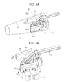
- the sticking means 39 comprises label sticking arms 40, 41 as shown in Figure 4A.
- the label sticking arms 40, 41 are a pair of arm members that can freely approach and leave each other by integrally moving in the direction of arrow D3 in the figure.
- the label sticking arms 40, 41 can move in a direction in which they approach each other to contract (reduce the width between the arms) or move in a direction in which they leave each other to expand (increase the width). Accordingly, the width of the label sticking arms 40, 41 is reduced to enable the label sticking arms 40, 41 to be inserted through the take up tube T1 and the width of the label sticking arms 40, 41 is then increased to enable each of the label sticking arms 40, 41 to abut against and adhere to an inner wall of the take up tube T1.
- the label sticking arm 41 has suction holes 42 to which suction pipes 43 are connected as shown in Figure 4B.
- the label sticking arm 41 thus sucks and holds the label LA on which the predetermined information is recorded and sticks it to an inner surface TA of the take up tube T1 by increasing the width between the label sticking arms 40, 41 so as to press it against the inner surface TA of the take up tube T1.
- suction holes 42 and suction pipes 43 constitute suction means provided in the sticking means 39.
- Each of the label sticking arms 40, 41 has a surface adhering to the inner surface TA of the take up tube T1.
- the pair of label sticking arms 40, 41 moves so as to increase the width between the label sticking arms 40, 41. This allows the surfaces 40a, 41a of the label sticking arms 40, 41, respectively to adhere reliably to the inner surface TA of the take up tube T1.
- the pair of label sticking arms 40, 41 with their width reduced can be inserted through the take up tube T1 so as to be fitted through the take up tube T1.
- the sticking means 39 holding the label LA with the recorded predetermined information can be allowed to stand by at a predetermined position on the conveyor.
- the sticking means 39 holding the label LA with the recorded predetermined information can be stopped at the stopping means 4 and then inserted into a larger diameter portion T1 a of the take up tube T1 corresponding to its leading side.
- the width between the paired label sticking arms 40, 41 is increased. This allows the surfaces 40a, 41a of the label sticking arms 40, 41 to adhere to the inner surface TA of the take up tube T1.
- the label LA sucked to the surface 41a, having the suction holes 42 can be stuck reliably or firmly.
- the predetermined information can be immediately recorded on a label LA, which can then be stuck to the take up tube T1.
- the sticking means 39 can suck and hold the label LA on which the predetermined information is recorded, and then immediately move it to the take up tube T1. This suitably enables a reduction in the time required to stick the label LA.
- the take up tube T1 to which the label LA with the recorded predetermined information is stuck is received by the doffing device 1 in the predetermined winding unit 10, which is to perform a doffing operation.
- the take up tube T1 is installed in the cradle 11 D as a new take up tube, and a new winding operation is started.
- Running of the doffing device 1 is controlled on the basis of conditions preset in a built-in controller 6.
- the controller 6 is drivingly controlled on the basis of instructions from a main controller 8 in a control box connected to the controller 6 via a cable installed in a flexible cable bare wire 7 provided along the rail 22B.
- this information is transmitted by the main controller 8 to the controller 6 in the doffing device 1 and a controller in the tube supplying device. This makes it possible to perform control such that the doffing device 1 is stopped at the predetermined winding unit requiring a doffing operation and such that the tube supplying device feeds out a new tube. Control is also performed such that the label supplying means 5 records the predetermined information on a label and such that the label sticking device 3 is actuated.
- Some automatic winders have a tube stocker in each winding unit in which take up tubes are stored. These automatic winders can pre-supply the tube stocker in the predetermined winding unit with a plurality of take up tubes to which labels with the recorded predetermined information are stuck. This configuration enables a doffing operation to be performed quickly in the predetermined winding unit without the need to wait for a conveyed new take up tube to arrive.
- the automatic winder comprises the doffing device that reciprocates among the plurality of winding units to unload full winding packages from winding units on which a winding operation has been finished and then to supply the winding units with empty take up tubes to allow a new winding operation to be resumed.
- the doffing device receives and supplies a take up tube to which a label with recorded predetermined information is stuck, to a predetermined winding unit. This enables a take up tube with accurate winding information to be supplied to each winding unit.
- each winding packaged formed can be accurately identified.
- the label is stuck to the inside of the take up tube. This prevents the label from peeling off from the package even when the package comes into contact with another during conveyance or an operator touches the package. The label can thus be reliably stuck to the winding package.
- the information recorded on the label is one of or a combination of any of date information, unit information, machine information, and yarn type information. This makes it possible to selectively record winding information required as production management information for the automatic winder. Winding packages can therefore be automatically produced to which labels with the recorded predetermined information are stuck.
- any of the following examples is applicable to recording of the predetermined information on the label: a scheme of printing text information directly on the label, a scheme of printing a barcode having the predetermined information on the label, and a scheme of embedding or sticking an IC chip in which the information is recorded, in or to the label.
- the label on which the predetermined information is recorded is, for example, the label on which the predetermined information is printed, on which the barcode indicating the predetermined information is printed, or which comprises the IC chip in which the predetermined information is recorded.
- the recording scheme is not particularly limited.
- the label LA shown in Figure 4B is only an example of the label on which the predetermined information is printed.
- the following information is printed on the label: 2005 24/MAR (March 24, 2005) as date information, MC1 (machine no. 1) as machine information, SP17 (unit no. 17) as unit information, and A-1 00 (lot number) as yarn type information.
- an automatic winder with the label sticking device in accordance with the present invention reliably supplies a predetermined winding unit with a take up tube to which a label with recorded predetermined information is stuck. This enables the formation of a winding package with accurate information.
- the present invention also makes it possible to accurately display the quality of winding packages and to automate unloading of winding packages and installation of new take up tubes. The present invention is thus effective on multikind and small quantity production.
Landscapes
- Labeling Devices (AREA)
- Replacing, Conveying, And Pick-Finding For Filamentary Materials (AREA)
- Spinning Or Twisting Of Yarns (AREA)
Abstract
Description
- The present invention relates to an automatic winder that rewinds a yarn wound around a supplying package such as a spinning bobbin to form a winding package of a larger diameter, and in particular, to an automatic winder comprising a label sticking device that sticks a label on which predetermined information is recorded, to a take up tube.
- In the prior art, a specified length of yarn from each spinning bobbin produced by a ring spinning machine is wound into a winding package of a larger diameter by an automatic winder.
- The automatic winder comprises a plurality of winding units arranged and a doffing device that reciprocates among the plurality of winding units to unload full winding packages from winding units on which a winding operation has been finished and then to supply empty tubes to the winding units.
- In unloading a full winding package with a predetermined length of yarn from a winding unit, the doffing device catches a yarn from a supplying package, and the doffing device subsequently supplies a new take up tube tube to the winding unit and then installs the yarn on the new take up tube.
- The winding unit is supplied with a new take up tube as described below. In response to a request signal from the winding unit on which a winding operation has been finished, a next, new take up tube is unloaded from a tube supplying device disposed at an end of the machine, and the take up tube is conveyed to the winding unit via a take up tube transporting conveyor. The take up tube conveyed on the conveyor is caught by the doffing device, and the winding tube is then installed in a cradle in the predetermined winding unit or supplied to a tube stocker disposed in the winding unit.
- To achieve the above operation, the tube supplying device, conveyor, and doffing device cooperate in supplying the predetermined winding unit with a take up tube in accordance with a request from the winding unit so that the winding unit can resume a new winding operation.
- Winding information needs to be displayed on a winding package; the winding information includes the lot number of a yarn to be wound, the date on which the package was produced, and the number of the winding machine or winding unit that produced the package. To achieve this requirement, the present applicant has applied for a patent on a method for managing the quality of a package during a doffing operation; the method sticks a label with the winding information to a surface of the package (see, for example, the Unexamined
Japanese Patent Application Publication (Tokkai-Hei) No. 4-75974 - Where the doffing device sticks a label with the winding information to the surface of each winding package during a doffing operation, the winding information can be displayed on all winding packages.
- However, the label stuck to the surface of the winding package may peel off during the conveyance of the package or when the package contacts another.
- Sticking the label to the surface of the winding package requires selection of an adhesive that does not affect yarn quality, and using a high-adhesive-power adhesive is thus difficult.
- It is an object of the present invention to solve the above problem by providing an automatic winder which can display winding information on each winding package and which prevents the displayed winding information from being lost during the conveyance of the winding package.
- To achieve the above object, an invention in accordance with
Claim 1 provides an automatic winder comprising a plurality of winding units each of which winds a yarn around a take up tube installed in a take up tube holding member to form a winding package and a doffing device that moves among the plurality of winding units to unload full winding packages from the winding units and to supply empty take up tubes to the winding units, the automatic winder being characterized by comprising label sticking device having label supplying means for supplying labels on which predetermined information is recorded and sticking means for sticking each of the labels from the label supplying means to an inside of a corresponding one of the take up tubes. - The invention in accordance with the
Claim 1 configured as described above provides the label sticking device that can stick the label to the inside of the take up tube conveyed by the conveyor. - An invention in accordance with
Claim 2 is characterized in that the label sticking means has a pair of label sticking arms which can freely approach and leave each other and which abut against the inside of the take up tube on moving in a direction in which the label sticking means leave each other and in that one of the arms has a function for sucking and holding the label on which the predetermined information is recorded and the paired label sticking arms leave each other to press and stick the label to the inside of the take up tube. - The invention in accordance with
Claim 2 configured as described above opens the pair of label sticking arms to allow them to adhere to the inside of the take up tube. This enables the label on which the predetermined information is recorded to be reliably stuck to the inside of the tube. - An invention in accordance with
Claim 3 is characterized in that each of the label sticking arms has a surface that adheres to an inner surface of the take up tube, and the paired label sticking arms move and leave each other in a direction in which a width between the arms increases, so that the surface of each of the label sticking arms adheres to the inner surface of the take up tube to reliably stick the label to the inside of the take up tube. - The invention in accordance with
Claim 3 configured as described above enables even a tapered take up tube to be reliably fixed. - An invention in accordance with Claim 4 provides an automatic winder comprising a doffing device that reciprocates among a plurality of winding units to unload full winding packages from winding units on which a winding operation has been finished and then to supply the winding units with empty take up tubes to allow a new winding operation to be resumed, the automatic winder being characterized by comprising the label sticking device for take up tubes set forth in any one of
Claims 1 to 3 and in that the doffing device receives and supplies a take up tube to which a label with recorded predetermined information is stuck, to a predetermined winding unit. - The invention in accordance with Claim 4 configured as described above provides an automatic winder that supplies, during a doffing operation, a take up tube to which the label with the recorded predetermined information is stuck to allow a new winding operation to be resumed.
- An invention in accordance with
Claim 5 is characterized in that the take up tube to which the label with the recorded predetermined information is stuck is conveyed to the predetermined winding unit via a conveyor, and the doffing device stopped at the predetermined winding unit receives the take up tube and then installs the take up tube directly in a cradle in the winding unit or supplies the take up tube to a tube stocker provided in the winding unit. - The invention in accordance with
Claim 5 configured as described above ensures that the predetermined winding unit is supplied with the take up tube to which the label with the recorded predetermined information is stuck. This enables the formation of a winding package with accurate information. - An invention in accordance with
Claim 6 is characterized in that the predetermined information is one of or a combination of any of date information, unit information, machine information, and yarn type information. - The invention in accordance with
Claim 6 configured as described above enables sticking of a label on which production management information required to identify the corresponding winding package is recorded. - The present invention sticks the label on which the predetermined information is recorded, to the inside of the take up tube. The present invention thus provides a label sticking device that can stick the label that, once stuck, does not peel off easily. An automatic winder in accordance with the present invention installs, in the predetermined winding unit, the take up tube to which the label with the recorded predetermined information is stuck, while the doffing device is performing a doffing operation. The automatic winder in accordance with present invention can thus form a winding package to which the label that, once stuck, does not peel off easily is stuck to allow the winding package to be easily identified.
- With reference to the enclosed Figures, a description will be given of an embodiment of an automatic winder comprising a label sticking device for take up tubes in accordance with the present invention.
- Figure 1 is a general front view of an automatic winder comprising a label sticking device for take up tubes in accordance with the present invention.
- Figure 2 is a sectional view of the automatic winder.
- Figure 3 is a schematic perspective view of the label sticking device for take up tubes in accordance with the present invention.
- Figure 4 is a schematic diagram illustrating how a label is stuck to a take up tube; Figure 4A is a side view and Figure 4B is a sectional view.
- First, the general configuration of an automatic winder W will be described with reference to Figures 1 and 2. As shown in the figures, the automatic winder W has a large number of
winding units 10 arranged in a line. Each of thewinding units 10 unwinds and draws out a yarn Y from a supplying bobbin B supplied to a lower part of the main body. Thewinding unit 10 then winds the yarn Y around a take up tube T rotatably held in a cradle (take up tube holding member) 11 D located in an upper part of the winding unit. A winding package P of a large diameter is thus formed. - Each
winding unit 10 comprises a yarn clearer 11A which detects a yarn defect and which has a yarn cutting function, asplicing device 11B, a traversingdrum 11C that rotates while traversing the yarn Y, thecradle 11 D that rotatably supports the take up tube T, a lower yarn sucking and holdingmember 12A that sucks and catches an end of the yarn Y drawn out from the supplying bobbin B to introduce the yarn end into thesplicing device 11 B, and asuction arm 12B that sucks and catches a winding-end yarn end on the winding package P to introduce the yarn end into thesplicing device 11 B, thesuction arm 12B serving as an upper yarn sucking and holding member. - The above configuration of the automatic winder W enables each
winding unit 10 to wind the yarns Y drawn out from a plurality of supplying bobbins B while splicing them to each other, to form a single winding package P of a larger diameter. Further, when a yarn defect in the yarn Y being wound is detected, the defective portion is cut and removed, and the resulting winding package-side yarn end is then spliced to the resulting supplying bobbin-side yarn end. This enables the formation of a winding package P without any yarn defect. - The automatic winder W winds a preset length of yarn Y into the winding package P.
A doffing device 1 is disposed in the automatic winder W; thedoffing device 1 is an automatic machine that performs a doffing operation of replacing a full winding package with a predetermined yarn length, with a new, empty take up tube T. - The
doffing device 1 is movable along a longitudinal direction of the machine so as to perform a doffing operation on each of the large number ofwinding units 10 arranged in the automatic winder W in a line in the longitudinal direction. Thedoffing device 1 thus moves along arail 22B installed in aframe 22A disposed in an upper part of a windermain body 20. Thedoffing device 1 then unloads each of the winding packages P in the large number ofwinding units 10 from thecorresponding cradle 11 D and installs a new, empty take up tube T in eachcradle 11 D. - A full winding package P is unloaded from the
cradle 11 D by thedoffing device 1 and then conveyed to a predetermined position by a conveyor (conveying means) 21A installed in the rear of the machine, and the full package P is then discharged from the automatic winder W. Thedoffing device 1 further receives the take up tube T conveyed along theconveyor 2 to install it in thecradle 11 D. - The take up tube T is unloaded from a tube supply device TS disposed at an end of the machine and conveyed to the winding unit side via the
label sticking device 3 by thepredetermined conveyor 2. The take up tube T conveyed on theconveyor 2 is stopped at a predetermined winding unit and caught by thedoffing device 1, which performs a doffing operation. The take up tube T is then installed in thecradle 11 D in the predetermined winding unit. - A take up tube T1 conveyed to and held in the
label sticking device 3 is thus pre-specified to be installed in a predetermined winding unit. Accordingly, predetermined information such as the unit number (spindle number) of this winding unit is recorded. As described later, thelabel sticking device 3 sticks a label on which the predetermined information is recorded, to the inside of the take up tube T1. - Now, the
label sticking device 3 will be described with reference to Figure 3. - The
label sticking device 3 comprises stopping means 4 for stopping the empty take up tube T1 conveyed along theconveyor 2, label supplying means 5 for supplying a label on which the predetermined information is recorded, and stickingmeans 39 for receiving the label on which the predetermined information is recorded, from the label supplying means 5 to stick the label to the inside of the take up tube T1. - The stopping means 4 can be displaced, by a
cylinder 4A, between a position where the take up tube T1 conveyed on theconveyor 2 is stopped and a position where the stoppage of the take up tube T1 is cleared to enable the conveyance of the take up tube T1 to be resumed. The label supplying means 5 comprises a mountroll holding portion 51 that holds amount roll 50 around which a mount P is wound; a large number of labels LA are stuck to the mount P at predetermined pitches. The label supplying means 5 also comprises alabel recording portion 52 that records the predetermine information on each of the labels LA and alabel separating portion 53 that peels off the label LA from the mount P. - The label LA located at the
label separating portion 53 is sucked, held, and peeled off from the mount P by thesticking means 39, described later. - As shown in the figure, the
label sticking device 3 comprises acylinder member 31, aslide rod 32, aslide block 33, and aholding member 34. Thelabel sticking device 3 can reciprocate the holdingmember 34 in the direction of arrow D1. Thelabel sticking device 3 also comprises anupstanding plate 38 and sticking means 30 that are movable in the direction of arrow D2 via acylinder 35 installed on the holdingmember 34. Theupstanding plate 38 and the sticking means 39 can thus reciprocate between an illustrated standby position and a position where acylinder rod 31 a of thecylinder member 31 contracts to receives the label LA supplied by thelabel supplying means 5. - The sticking means 39 comprises sucking means (not shown in the drawings) for sucking and holding the label LA, and the sticking means 39 moves to the
label supplying means 5 to receive the label LA on which the predetermined information is recorded, from the supplying means. The label LA is then stuck to the inside of the take up tube T1 by an arm member that enters the take up tube T1; the take up tube T1 is conveyed on the conveyor with its larger diameter portion Ta at a leading position. - The
label sticking device 3 has apressing member 4C comprising acylinder 4B, and which presses and fixes the take up tube T1 on sticking the label LA to the take up tube T1. The label sticking means 3 stops the take up tube T1 by means of the stopping means 4 and then moves thepressing member 4C in the direction of the downward arrow in the figure to fix the take up tube T1. With these conditions maintained, thelabel sticking device 3 moves the stopping means 4 upward and inserts the sticking means 39 into the take up tube T1 to perform a label sticking operation. This prevents the take up tube T1 from being moved while the label LA is being stuck, thus enabling the label LA to be always stuck to the same position. - The labels LA are stuck to the mount P at the predetermined pitches, and the
label recording portion 52 records the predetermined information on each label LA. The sticking means 39 further separates and peels off each label LA on which the predetermined information is recorded, from the mount P and then holds it. The information includes one of or a combination of any (winding information) of the date on which winding is to be carried out, unit number information, machine information, and yarn type information. - The
mount roll 50, around which the mount P is wound, has a large number of the labels LA stuck to itself, and the mount P is drawn out from themount roll 50, installed around the mountroll holding portion 51. Thelabel recording portion 52 records the predetermined information on the labels LA, and thelabel separating portion 52 peels off the labels LA on which the predetermined information is recorded, from the mount P. - Thus, when the
mount roll 50 has labels LA the number of which is equal to the number of times that the single automatic winder W comprising the large number of winding units performs a doffing operation in a day, themount roll 50 needs to be replaced with a new one only once a day. - When a new take up tube T1 is supplied to the
conveyor 2 in response to a doffing request from the machine, thelabel recording portion 52 records predetermined information on a label LA. The sticking means 39 receives and holds, by suction, the label LA on which the predetermined information is recorded. The sticking means 39 is then moved to the standby position shown in the figure, by means of thecylinder member 31, and the sticking means 39 thus stands by at a predetermined position on the route of theconveyor 2. - The sticking means 39 comprises
label sticking arms label sticking arms label sticking arms label sticking arms label sticking arms label sticking arms label sticking arms - The
label sticking arm 41 has suction holes 42 to whichsuction pipes 43 are connected as shown in Figure 4B. Thelabel sticking arm 41 thus sucks and holds the label LA on which the predetermined information is recorded and sticks it to an inner surface TA of the take up tube T1 by increasing the width between thelabel sticking arms - That is to say, the suction holes 42 and
suction pipes 43 constitute suction means provided in the sticking means 39. - Each of the
label sticking arms label sticking arms label sticking arms surfaces label sticking arms - Thus, the pair of
label sticking arms - After the sticking means 39 is inserted into the larger diameter portion T1 a of the take up tube T1, the width between the paired
label sticking arms surfaces label sticking arms surface 41a, having the suction holes 42, can be stuck reliably or firmly. - To improve the efficiency of the machine, it is possible to pre-convey the next take up tube T1 to the stopping means 4. Then, in response to a doffing instruction for a predetermined winding unit, the predetermined information can be immediately recorded on a label LA, which can then be stuck to the take up tube T1.
- With the above configuration, when the need for a doffing operation arises, recording of the predetermined information can be immediately started. Further, the sticking means 39 can suck and hold the label LA on which the predetermined information is recorded, and then immediately move it to the take up tube T1. This suitably enables a reduction in the time required to stick the label LA.
- The take up tube T1 to which the label LA with the recorded predetermined information is stuck is received by the
doffing device 1 in the predetermined windingunit 10, which is to perform a doffing operation. The take up tube T1 is installed in thecradle 11 D as a new take up tube, and a new winding operation is started. - Running of the
doffing device 1 is controlled on the basis of conditions preset in a built-incontroller 6. Thecontroller 6 is drivingly controlled on the basis of instructions from amain controller 8 in a control box connected to thecontroller 6 via a cable installed in a flexible cable bare wire 7 provided along therail 22B. - When the predetermined winding unit completes winding and requires a doffing operation, this information is transmitted by the
main controller 8 to thecontroller 6 in thedoffing device 1 and a controller in the tube supplying device. This makes it possible to perform control such that thedoffing device 1 is stopped at the predetermined winding unit requiring a doffing operation and such that the tube supplying device feeds out a new tube. Control is also performed such that the label supplying means 5 records the predetermined information on a label and such that thelabel sticking device 3 is actuated. - Some automatic winders have a tube stocker in each winding unit in which take up tubes are stored. These automatic winders can pre-supply the tube stocker in the predetermined winding unit with a plurality of take up tubes to which labels with the recorded predetermined information are stuck. This configuration enables a doffing operation to be performed quickly in the predetermined winding unit without the need to wait for a conveyed new take up tube to arrive.
- As described above, the automatic winder comprises the doffing device that reciprocates among the plurality of winding units to unload full winding packages from winding units on which a winding operation has been finished and then to supply the winding units with empty take up tubes to allow a new winding operation to be resumed. The doffing device receives and supplies a take up tube to which a label with recorded predetermined information is stuck, to a predetermined winding unit. This enables a take up tube with accurate winding information to be supplied to each winding unit.
- Consequently, each winding packaged formed can be accurately identified. Moreover, the label is stuck to the inside of the take up tube. This prevents the label from peeling off from the package even when the package comes into contact with another during conveyance or an operator touches the package. The label can thus be reliably stuck to the winding package.
- Furthermore, the information recorded on the label is one of or a combination of any of date information, unit information, machine information, and yarn type information. This makes it possible to selectively record winding information required as production management information for the automatic winder. Winding packages can therefore be automatically produced to which labels with the recorded predetermined information are stuck.
- Any of the following examples is applicable to recording of the predetermined information on the label: a scheme of printing text information directly on the label, a scheme of printing a barcode having the predetermined information on the label, and a scheme of embedding or sticking an IC chip in which the information is recorded, in or to the label.
- In other words, the label on which the predetermined information is recorded is, for example, the label on which the predetermined information is printed, on which the barcode indicating the predetermined information is printed, or which comprises the IC chip in which the predetermined information is recorded. The recording scheme is not particularly limited.
- For example, the label LA shown in Figure 4B is only an example of the label on which the predetermined information is printed. In this example, the following information is printed on the label: 2005 24/MAR (March 24, 2005) as date information, MC1 (machine no. 1) as machine information, SP17 (unit no. 17) as unit information, and A-1 00 (lot number) as yarn type information.
- Thus, an automatic winder with the label sticking device in accordance with the present invention reliably supplies a predetermined winding unit with a take up tube to which a label with recorded predetermined information is stuck. This enables the formation of a winding package with accurate information. The present invention also makes it possible to accurately display the quality of winding packages and to automate unloading of winding packages and installation of new take up tubes. The present invention is thus effective on multikind and small quantity production.
Claims (7)
- An automatic winder comprising a plurality of winding units each of which winds a yarn around a take up tube installed in a take up tube holding member to form a winding package and a doffing device that moves among the plurality of winding units to unload full winding packages from the winding units and to supply empty take up tubes to the winding units, the automatic winder being characterized by comprising label sticking device having label supplying means for supplying labels on which predetermined information is recorded and sticking means for sticking each of the labels from the label supplying means to an inside of a corresponding one of the take up tubes.
- An automatic winder according to Claim 1, characterized by further comprising take up tube supplying means for supplying the empty take up tubes and conveying means for conveying the take up tubes from the take up tube supplying device to the plurality of winding units and in that the label sticking means is provided in a middle of the conveying means and the label sticking device has stopping means for stopping the empty take up tube conveyed by the conveying means, at a predetermined position, and in that the sticking means sticks the label to the empty take up tube stopped by the stopping means and the doffing device supplies the winding unit with the empty take up tube conveyed by the conveying means and to which the label has been stuck.
- An automatic winder according to Claim 2, characterized in that the predetermined information is unit number information on the winding units, the label sticking device sticks a label on which the unit number information on a predetermined winding unit are recorded, to the empty take up tube, and the doffing device supplies the empty take up tube to the winding unit with the unit number recorded on the label.
- An automatic winder according to Claim 3, characterized in that the label sticking device records the unit number of the winding unit from which the full winding package has been unloaded, on the label, and then sticks the label to the empty take up tube, and the doffing device supplies the labeled empty take up tube to the winding unit from which the full winding package has been unloaded.
- An automatic winder according to Claim 4, characterized in that each winding unit has a tube stocker in which empty take up tubes are stored, and the doffing device supplies the labeled take up tube to the tube stocker in the winding unit from which the full winding package has been unloaded, and supplies the empty take up tube from the tube stocker to the take up tube holding member.
- An automatic winder according to any one of Claim 1 to 4, characterized in that the label sticking means has a pair of label sticking arms which can freely approach and leave each other and which abut against the inside of the take up tube on moving in a direction in which the label sticking means leave each other and in that one of the label sticking arms has a function for sucking and holding the label on which the predetermined information is recorded and the paired label sticking arms leave each other to press and stick the label to the inside of the take up tube.
- An automatic winder according to Claim 6, characterized in that each of the label sticking arms has a surface that adheres to an inner surface of the take up tube, and the paired label sticking arms move and leave each other in a direction in which a width between the label sticking arms increases, so that the surface of each of the label sticking arms adheres to the inner surface of the take up tube to reliably stick the label to the inside of the take up tube.
Applications Claiming Priority (1)
| Application Number | Priority Date | Filing Date | Title |
|---|---|---|---|
| JP2005164024A JP4760145B2 (en) | 2005-06-03 | 2005-06-03 | Winding tube labeling device and automatic winder |
Publications (2)
| Publication Number | Publication Date |
|---|---|
| EP1728750A2 true EP1728750A2 (en) | 2006-12-06 |
| EP1728750A3 EP1728750A3 (en) | 2007-08-15 |
Family
ID=36777680
Family Applications (1)
| Application Number | Title | Priority Date | Filing Date |
|---|---|---|---|
| EP06112990A Withdrawn EP1728750A3 (en) | 2005-06-03 | 2006-04-24 | Automatic winder comprising device sticking label to take up tube |
Country Status (2)
| Country | Link |
|---|---|
| EP (1) | EP1728750A3 (en) |
| JP (1) | JP4760145B2 (en) |
Cited By (4)
| Publication number | Priority date | Publication date | Assignee | Title |
|---|---|---|---|---|
| CN109928270A (en) * | 2018-12-05 | 2019-06-25 | 陈志远 | A kind of full-automatic winding apparatus |
| CN111747227A (en) * | 2019-03-27 | 2020-10-09 | 塞维欧纺织机械股份公司 | Tube for tracking a winding drum, winding device with a drum tracking device and winding method |
| CN112278483A (en) * | 2020-11-02 | 2021-01-29 | 合肥柱石科技有限公司 | Labeling part for pasting label |
| CN112407509A (en) * | 2020-11-20 | 2021-02-26 | 合肥柱石科技有限公司 | Product packaging and labeling mechanism made of deformable materials |
Families Citing this family (3)
| Publication number | Priority date | Publication date | Assignee | Title |
|---|---|---|---|---|
| CN112278490B (en) * | 2020-11-02 | 2022-03-29 | 合肥柱石科技有限公司 | Labeling mechanism for pasting labels |
| CN117105010B (en) | 2023-09-08 | 2026-03-20 | 浙江恒逸石化有限公司 | Automatic drop-out communication methods, systems and equipment |
| CN117246609B (en) | 2023-11-15 | 2024-01-30 | 浙江恒逸石化有限公司 | Silk spindle coding method, device, electronic equipment and storage medium |
Citations (1)
| Publication number | Priority date | Publication date | Assignee | Title |
|---|---|---|---|---|
| JPH0475974A (en) | 1990-07-18 | 1992-03-10 | Murata Mach Ltd | Package quality managing method |
Family Cites Families (15)
| Publication number | Priority date | Publication date | Assignee | Title |
|---|---|---|---|---|
| BE628530A (en) * | 1962-02-17 | |||
| JPS58188807U (en) * | 1982-06-11 | 1983-12-15 | 株式会社フジクラ | Bobbin labeling device |
| JPS616336A (en) * | 1984-06-15 | 1986-01-13 | Teijin Ltd | Spindle controlling method in spinning process |
| US4616992A (en) * | 1985-06-12 | 1986-10-14 | Y Technipak Corp. | Shuttle-type blow molding machine with in-mold labeling |
| DE3733511A1 (en) * | 1987-10-03 | 1989-04-13 | Schlafhorst & Co W | Method and apparatus for the marking of tubes |
| JP2501896B2 (en) * | 1989-03-08 | 1996-05-29 | 富士電機株式会社 | Automatic bar code label attachment device |
| DE3912488A1 (en) * | 1989-04-15 | 1990-10-18 | Schlafhorst & Co W | METHOD AND DEVICE FOR TRANSMITTING PRODUCT INFORMATION AND PROPERTIES OF A TEXTILE REEL BY MEANS OF AN INFORMATION CARRIER |
| JP2513897B2 (en) * | 1990-04-12 | 1996-07-03 | 村田機械株式会社 | Spinning plant production management system |
| JPH0634250B2 (en) * | 1990-10-29 | 1994-05-02 | オカベマーキングシステム株式会社 | Printing device for labels, tags, etc. |
| JP3530575B2 (en) * | 1994-05-24 | 2004-05-24 | 多摩川精機株式会社 | Label sticking method |
| CA2213959A1 (en) * | 1996-09-23 | 1998-03-23 | Eastman Kodak Company | Mechanism for applying labels to the inside of a carton |
| NL1019324C2 (en) * | 2001-11-07 | 2003-05-08 | Novem Internat B V | Method and device for placing labels. |
| JP2003300513A (en) * | 2002-04-12 | 2003-10-21 | Yokohama Rubber Co Ltd:The | Method and device for fixing end of string member as to string member winding device |
| JP2004210302A (en) * | 2002-12-27 | 2004-07-29 | Lintec Corp | Label affixing device and label affixing method |
| ATA5312003A (en) * | 2003-04-07 | 2005-08-15 | Fries Planung & Marketing | DEVICE FOR ATTACHING AN IMPRINT |
-
2005
- 2005-06-03 JP JP2005164024A patent/JP4760145B2/en not_active Expired - Fee Related
-
2006
- 2006-04-24 EP EP06112990A patent/EP1728750A3/en not_active Withdrawn
Patent Citations (1)
| Publication number | Priority date | Publication date | Assignee | Title |
|---|---|---|---|---|
| JPH0475974A (en) | 1990-07-18 | 1992-03-10 | Murata Mach Ltd | Package quality managing method |
Cited By (5)
| Publication number | Priority date | Publication date | Assignee | Title |
|---|---|---|---|---|
| CN109928270A (en) * | 2018-12-05 | 2019-06-25 | 陈志远 | A kind of full-automatic winding apparatus |
| CN109928270B (en) * | 2018-12-05 | 2024-03-01 | 钟祥市合兴绳缆科技有限公司 | A fully automatic shaft driving machine |
| CN111747227A (en) * | 2019-03-27 | 2020-10-09 | 塞维欧纺织机械股份公司 | Tube for tracking a winding drum, winding device with a drum tracking device and winding method |
| CN112278483A (en) * | 2020-11-02 | 2021-01-29 | 合肥柱石科技有限公司 | Labeling part for pasting label |
| CN112407509A (en) * | 2020-11-20 | 2021-02-26 | 合肥柱石科技有限公司 | Product packaging and labeling mechanism made of deformable materials |
Also Published As
| Publication number | Publication date |
|---|---|
| JP2006335442A (en) | 2006-12-14 |
| JP4760145B2 (en) | 2011-08-31 |
| EP1728750A3 (en) | 2007-08-15 |
Similar Documents
| Publication | Publication Date | Title |
|---|---|---|
| CN102471008B (en) | Management system for automatic winder and automatic winder | |
| EP2345612A2 (en) | Doffing apparatus | |
| CN106494937B (en) | Yarn winding device, automatic winder, textile machine system, and yarn feeding bobbin abnormality detection method | |
| CN109911707B (en) | How the service unit works | |
| CN110494380B (en) | Spinning system and winding stop method | |
| CN111039075B (en) | Bobbin processing device, yarn winding apparatus, and bobbin processing method | |
| CZ283034B6 (en) | Process and apparatus for supplying winding devices of textile machine with empty tubes | |
| IT9020048A1 (en) | PROCEDURE FOR THE TRANSMISSION OF INFORMATION AND PRODUCT CHARACTERISTICS OF A TEXTILE SPOOL BY MEANS OF AN INFORMATION SUPPORT | |
| CN101723206A (en) | Textile machine for creating cross-wound spools and method for operating the same | |
| JP4760145B2 (en) | Winding tube labeling device and automatic winder | |
| JP2016194187A (en) | Method for operating composite system comprising at least one ring spinning machine and at least one winding machine, and composite system | |
| JP4478344B2 (en) | A device that starts operation at the work site of a textile machine that produces cheese | |
| US7044417B2 (en) | High speed transfer takeup | |
| CN106087145B (en) | Method and Apparatus for Removing Defective Yarn Portions from a Table of an Open End Spinning Machine | |
| CN101405189B (en) | Method and apparatus for transporting label strips | |
| JP2021017313A (en) | Yarn winding system and yarn winding method | |
| JP2022167816A (en) | Method for replacing bobbin in spinning machine and spinning machine | |
| TWI904321B (en) | Yarn processing facility | |
| US5349807A (en) | Robot apparatus for double twister | |
| JP7848466B2 (en) | Method and apparatus for preparing spinning cups | |
| CN114789942B (en) | Silk thread processing equipment | |
| JP2017002416A (en) | Yarn winding-up system and yarn winding-up method | |
| EP3744670A1 (en) | Textile machine | |
| JP7564001B2 (en) | Yarn processing equipment | |
| CN115676486A (en) | Method for operating a winding machine and winding station and winding machine |
Legal Events
| Date | Code | Title | Description |
|---|---|---|---|
| PUAI | Public reference made under article 153(3) epc to a published international application that has entered the european phase |
Free format text: ORIGINAL CODE: 0009012 |
|
| AK | Designated contracting states |
Kind code of ref document: A2 Designated state(s): AT BE BG CH CY CZ DE DK EE ES FI FR GB GR HU IE IS IT LI LT LU LV MC NL PL PT RO SE SI SK TR |
|
| AX | Request for extension of the european patent |
Extension state: AL BA HR MK YU |
|
| PUAL | Search report despatched |
Free format text: ORIGINAL CODE: 0009013 |
|
| AK | Designated contracting states |
Kind code of ref document: A3 Designated state(s): AT BE BG CH CY CZ DE DK EE ES FI FR GB GR HU IE IS IT LI LT LU LV MC NL PL PT RO SE SI SK TR |
|
| AX | Request for extension of the european patent |
Extension state: AL BA HR MK YU |
|
| RIC1 | Information provided on ipc code assigned before grant |
Ipc: B65C 3/00 20060101ALI20070707BHEP Ipc: B65C 9/36 20060101ALI20070707BHEP Ipc: B65H 67/06 20060101AFI20060817BHEP |
|
| 17P | Request for examination filed |
Effective date: 20071109 |
|
| AKX | Designation fees paid |
Designated state(s): DE IT |
|
| 17Q | First examination report despatched |
Effective date: 20090206 |
|
| STAA | Information on the status of an ep patent application or granted ep patent |
Free format text: STATUS: THE APPLICATION IS DEEMED TO BE WITHDRAWN |
|
| 18D | Application deemed to be withdrawn |
Effective date: 20090617 |