EP1728653A2 - Système de suspension réglable - Google Patents
Système de suspension réglable Download PDFInfo
- Publication number
- EP1728653A2 EP1728653A2 EP06005229A EP06005229A EP1728653A2 EP 1728653 A2 EP1728653 A2 EP 1728653A2 EP 06005229 A EP06005229 A EP 06005229A EP 06005229 A EP06005229 A EP 06005229A EP 1728653 A2 EP1728653 A2 EP 1728653A2
- Authority
- EP
- European Patent Office
- Prior art keywords
- wheel suspension
- suspension according
- plate
- screw connections
- wheel
- Prior art date
- Legal status (The legal status is an assumption and is not a legal conclusion. Google has not performed a legal analysis and makes no representation as to the accuracy of the status listed.)
- Granted
Links
Images
Classifications
-
- B—PERFORMING OPERATIONS; TRANSPORTING
- B62—LAND VEHICLES FOR TRAVELLING OTHERWISE THAN ON RAILS
- B62D—MOTOR VEHICLES; TRAILERS
- B62D17/00—Means on vehicles for adjusting camber, castor, or toe-in
-
- B—PERFORMING OPERATIONS; TRANSPORTING
- B60—VEHICLES IN GENERAL
- B60G—VEHICLE SUSPENSION ARRANGEMENTS
- B60G7/00—Pivoted suspension arms; Accessories thereof
- B60G7/008—Attaching arms to unsprung part of vehicle
-
- B—PERFORMING OPERATIONS; TRANSPORTING
- B60—VEHICLES IN GENERAL
- B60G—VEHICLE SUSPENSION ARRANGEMENTS
- B60G2200/00—Indexing codes relating to suspension types
- B60G2200/40—Indexing codes relating to the wheels in the suspensions
- B60G2200/462—Toe-in/out
- B60G2200/4622—Alignment adjustment
-
- B—PERFORMING OPERATIONS; TRANSPORTING
- B60—VEHICLES IN GENERAL
- B60G—VEHICLE SUSPENSION ARRANGEMENTS
- B60G2204/00—Indexing codes related to suspensions per se or to auxiliary parts
- B60G2204/10—Mounting of suspension elements
- B60G2204/14—Mounting of suspension arms
- B60G2204/148—Mounting of suspension arms on the unsprung part of the vehicle, e.g. wheel knuckle or rigid axle
-
- B—PERFORMING OPERATIONS; TRANSPORTING
- B60—VEHICLES IN GENERAL
- B60G—VEHICLE SUSPENSION ARRANGEMENTS
- B60G2204/00—Indexing codes related to suspensions per se or to auxiliary parts
- B60G2204/40—Auxiliary suspension parts; Adjustment of suspensions
- B60G2204/416—Ball or spherical joints
-
- B—PERFORMING OPERATIONS; TRANSPORTING
- B60—VEHICLES IN GENERAL
- B60G—VEHICLE SUSPENSION ARRANGEMENTS
- B60G2204/00—Indexing codes related to suspensions per se or to auxiliary parts
- B60G2204/40—Auxiliary suspension parts; Adjustment of suspensions
- B60G2204/44—Centering or positioning means
-
- B—PERFORMING OPERATIONS; TRANSPORTING
- B60—VEHICLES IN GENERAL
- B60G—VEHICLE SUSPENSION ARRANGEMENTS
- B60G2204/00—Indexing codes related to suspensions per se or to auxiliary parts
- B60G2204/61—Adjustable during maintenance
-
- B—PERFORMING OPERATIONS; TRANSPORTING
- B60—VEHICLES IN GENERAL
- B60G—VEHICLE SUSPENSION ARRANGEMENTS
- B60G2206/00—Indexing codes related to the manufacturing of suspensions: constructional features, the materials used, procedures or tools
- B60G2206/01—Constructional features of suspension elements, e.g. arms, dampers, springs
- B60G2206/50—Constructional features of wheel supports or knuckles, e.g. steering knuckles, spindle attachments
Definitions
- the invention relates to a wheel suspension which has at least one wheel bearing unit which is detachably fastened to a handlebar and which comprises a stub axle.
- a suspension connects the wheels to the bodywork of a vehicle. Your job is, among other things, to guide the wheels.
- the position of the wheels is described by the spatial coordinates and the sizes track and camber and the elasticities of all components.
- Wheel suspensions on rear axles of passenger cars are often designed as a torsion beam axle. These are called welded assemblies produced. At the interface to the wheel bearing unit, beam steering axles must be machined. Machining achieves track / camber presetting.
- the invention has for its object to improve a suspension such that a machining at the interface between the handlebar and wheel bearing unit can be omitted, thereby saving labor and corrosion resistance of the handlebar should be increased.
- the core idea of the invention is to provide a carrier plate for fastening the wheel bearing unit on a handlebar of the suspension.
- the journal of the wheel bearing unit also has a contact head, which is articulated under the influence of a pressure plate in the receptacle of the support plate.
- the wheel bearing unit Due to the articulated support, the wheel bearing unit is mounted gimbal on the support plate or on the handlebar. Thus, an adjustment of the lane and camber values is possible.
- the setting of the lane and camber values can be done manually by suitable means. Vertical and horizontal forces occurring in the area of the suspension are also transferable through storage.
- the contact head of the axle journal can have a spherical section shaped contact surface. Due to the spherical segment-shaped design a rotationally movable in three axes storage is guaranteed.
- the carrier plate has a concave receptacle.
- a carrier plate can be produced particularly easily by embossing. It can have a circular opening in the middle. Through the opening, which is preferably circular, material can be saved and the production can be facilitated.
- the contact head can also have a pressure shoulder on which the pressure plate acts.
- the pressure shoulder is suitably designed as a heel on the journal.
- the pressure plate can be coupled via screw connections to the carrier plate generating clamping pressure. Screw connections facilitate the installation of the suspension. In addition, adjustment of the track and camber values is possible via the screw connections.
- the screw connections may have ball nuts and spherical washers, which are arranged on the axle journal opposite side of the support plate. Through the use of ball nuts and spherical washers it is ensured that the screw connection always has a secure, since full surface, support on the carrier plate. This is particularly advantageous for large camber or toe angles.
- the pressure plate and the carrier plate may be coupled via at least three screw connections. This ensures that the lane and camber values are adjustable. Conveniently, however, come four screw for coupling the pressure plate and the support plate for Commitment. This allows a particularly simple adjustment of the camber and lane values, since to adjust these values, the screw connections in the horizontal or vertical direction of the carrier plate only have to be alternately tightened and released in each case.
- a servomotor can be operated electrically, pneumatically or hydraulically.
- the servomotor is coupled to the screw.
- the coupling can be made such that on the servomotor opposite screw connections are mutually attractable and detachable.
- the ball nuts of the screw can be replaced by gears with an internal thread and a ball seat. Via a flat drive, these can interact with the drive shaft of the servomotor.
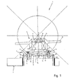
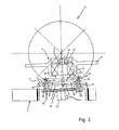
- FIG. 1 and 2 is a section of a suspension 1; 21 shown.
- the suspension 1; 21 includes a handlebar 2, to which a support plate 3 is welded for mounting a wheel bearing unit 4.
- the link 2 may be a wishbone or trailing arm.
- the support plate 3 has centrally a concave receptacle 5 for a journal 6 of the wheel bearing unit 4.
- the receptacle 5 has a central bore 7 to save material and to facilitate manufacturing.
- the support plate 3 has also four flange holes 8, through the screw 9; 25 are attached to attach the wheel bearing unit 4.
- the wheel bearing unit 4 comprises a journal 6, on which a ball bearing 10 is attached, which in turn carries a wheel hub 11.
- the ball bearing 10 is fixed on the axle journal 6 by means of an axle journal nut 12 arranged on the outside in conjunction with a disk 13 which rests on an inner ring of the ball bearing 10.
- the journal 6 has an abutment head 14, the spherical section shaped contact surface 15 is supported on the support plate 3.
- Between journal 6 and support plate 3 is a release layer 16 which causes a reduction in friction, whereby the pivoting of the wheel bearing unit 4 is facilitated.
- the release layer 16 may be made of Teflon or a grease layer or an oil film.
- the contact surface 15 is flattened at the end of the axle journal 6.
- a shoulder is provided as a pressure shoulder 17.
- a pressure plate 18 is pushed onto the axle journal 6 and acts on the contact head 14 via the pressure shoulder 17.
- screw 9; 25 couple the pressure plate 18 and the support plate 3, whereby clamping pressure can be generated, which ensures an exact positioning of the contact head in the support plate and the desired orientation of the wheel bearing unit 4 with respect to the lintel / toe setting.
- the screw 9; 25 have on the side facing away from the journal 6 of the support plate 3 supported on the support plate 3 ball washers 19 and ball nuts 20. By tightening and loosening the screw 9; 25, the wheel bearing unit 4 can be pivoted about a center Z, which is located outside of the journal 6 on the abutment head 14 opposite end side of the journal 6.
- the solution according to the invention makes it possible to set the camber and track values. In the figures 1 and 2, this is represented by the toe angle ⁇ .
- the setting can be changed as needed. For this purpose, only the ball nuts 20 of the screw 9; 25 to attract or solve accordingly.
- the wheel suspension 21 of FIG. 2 has ball seat thread gears 22 which are coupled to a servomotor 23 via a flat drive 24 instead of the ball nuts 20.
- a servomotor 23 is electrically operated.
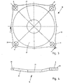
- FIG. 3 shows a pressure plate 18.
- the pressure plate 18 has a core hole 27, a cone portion 28 surrounding the core hole 27, and a screw-on flange 29 on the outside.
- the Anschraubflansch 29 has four symmetrically arranged flange holes 8 for screw 9; 25 on.
- the edge 30 of the pressure plate 18 is reinforced in the region of the flange holes 8 radially outward.
- the pressure plate 18 is substantially flat. Only the cone portion 28 has a conical taper toward the center. In the region of the core hole 27, the pressure plate 18 is slightly recessed with respect to the edge 30. In the image plane right part of the Anschraubflansches 29 is shown. The edge 30 is reinforced radially outwardly in this area and has a flange bore 8.
Landscapes
- Engineering & Computer Science (AREA)
- Mechanical Engineering (AREA)
- Chemical & Material Sciences (AREA)
- Combustion & Propulsion (AREA)
- Transportation (AREA)
- Vehicle Body Suspensions (AREA)
- Steering-Linkage Mechanisms And Four-Wheel Steering (AREA)
- Motorcycle And Bicycle Frame (AREA)
- Axle Suspensions And Sidecars For Cycles (AREA)
Applications Claiming Priority (1)
| Application Number | Priority Date | Filing Date | Title |
|---|---|---|---|
| DE102005025039A DE102005025039A1 (de) | 2005-05-30 | 2005-05-30 | Radaufhängung |
Publications (3)
| Publication Number | Publication Date |
|---|---|
| EP1728653A2 true EP1728653A2 (fr) | 2006-12-06 |
| EP1728653A3 EP1728653A3 (fr) | 2008-06-11 |
| EP1728653B1 EP1728653B1 (fr) | 2009-04-15 |
Family
ID=36809654
Family Applications (1)
| Application Number | Title | Priority Date | Filing Date |
|---|---|---|---|
| EP06005229A Not-in-force EP1728653B1 (fr) | 2005-05-30 | 2006-03-15 | Système de suspension réglable |
Country Status (3)
| Country | Link |
|---|---|
| EP (1) | EP1728653B1 (fr) |
| AT (1) | ATE428618T1 (fr) |
| DE (2) | DE102005025039A1 (fr) |
Cited By (2)
| Publication number | Priority date | Publication date | Assignee | Title |
|---|---|---|---|---|
| WO2010145752A1 (fr) * | 2009-06-19 | 2010-12-23 | Audi Ag | Dispositif de réglage du carrossage et/ou du parallélisme des roues d'une suspension |
| CN102164807A (zh) * | 2008-09-23 | 2011-08-24 | 奥迪股份公司 | 机动车轮悬架 |
Families Citing this family (5)
| Publication number | Priority date | Publication date | Assignee | Title |
|---|---|---|---|---|
| DE102007054823A1 (de) * | 2007-11-16 | 2009-05-20 | Audi Ag | Verstellvorrichtung für Radaufhängungen |
| DE102008028273A1 (de) | 2008-06-13 | 2009-12-17 | Benteler Automobiltechnik Gmbh | Radaufhängung |
| DE102008048567A1 (de) * | 2008-09-23 | 2010-03-25 | Audi Ag | Vorrichtung zum Verstellen eines Rades einer Radaufhängung |
| DE102009021093A1 (de) * | 2009-05-13 | 2010-11-18 | Audi Ag | Radaufhängung für ein Kraftfahrzeug |
| DE102013007515B4 (de) | 2013-05-02 | 2022-03-17 | Volkswagen Aktiengesellschaft | Achszapfen einer Radaufhängung eines Fahrzeugs |
Family Cites Families (10)
| Publication number | Priority date | Publication date | Assignee | Title |
|---|---|---|---|---|
| DE876211C (de) * | 1942-06-09 | 1953-05-11 | Daimler Benz Ag | Radanordnung fuer Kraftfahrzeuge mit parallelogrammartig unabhaengig gefuehrten Raedern |
| DE1455650A1 (de) * | 1963-12-20 | 1969-07-10 | Nsu Motorenwerke Ag | Daempfungsvorrichtung fuer Radaufhaengungen von Kraftfahrzeugen |
| JPS58191614A (ja) * | 1982-04-30 | 1983-11-08 | Mazda Motor Corp | リヤサスペンシヨン |
| US4752079A (en) * | 1985-07-31 | 1988-06-21 | Surfco | Enhanced traction wheel assembly |
| JPS63162313A (ja) * | 1986-12-26 | 1988-07-05 | Honda Motor Co Ltd | 自動車のサスペンシヨン装置 |
| DE3928135A1 (de) * | 1988-08-31 | 1990-03-01 | Volkswagen Ag | Radaufhaengung fuer kraftfahrzeuge, insbesondere fuer personenkraftwagen |
| NL1002490C2 (nl) * | 1996-02-29 | 1997-09-01 | Netherlands Car Bv | Motorvoertuig. |
| US6374665B1 (en) * | 2000-01-21 | 2002-04-23 | Goodyear Tire & Rubber Company | Apparatus for adjusting the cant of an annular article |
| EP1275534A1 (fr) * | 2001-07-10 | 2003-01-15 | Société de Technologie Michelin | Suspension à carrossage variable pour véhicule automobile |
| KR100572264B1 (ko) * | 2004-12-23 | 2006-04-24 | (주) 동희산업 | 차량 현가시스템의 휠 각도 조절장치 |
-
2005
- 2005-05-30 DE DE102005025039A patent/DE102005025039A1/de not_active Withdrawn
-
2006
- 2006-03-15 EP EP06005229A patent/EP1728653B1/fr not_active Not-in-force
- 2006-03-15 AT AT06005229T patent/ATE428618T1/de active
- 2006-03-15 DE DE502006003417T patent/DE502006003417D1/de active Active
Non-Patent Citations (1)
| Title |
|---|
| None |
Cited By (6)
| Publication number | Priority date | Publication date | Assignee | Title |
|---|---|---|---|---|
| CN102164807A (zh) * | 2008-09-23 | 2011-08-24 | 奥迪股份公司 | 机动车轮悬架 |
| CN102164807B (zh) * | 2008-09-23 | 2013-06-19 | 奥迪股份公司 | 机动车轮悬架 |
| WO2010145752A1 (fr) * | 2009-06-19 | 2010-12-23 | Audi Ag | Dispositif de réglage du carrossage et/ou du parallélisme des roues d'une suspension |
| CN102802971A (zh) * | 2009-06-19 | 2012-11-28 | 奥迪股份公司 | 用于调节轮悬架结构的车轮外倾和/或轮距的装置 |
| US8371593B2 (en) | 2009-06-19 | 2013-02-12 | Audi Ag | Device for adjusting camber and/or toe of the wheels of a wheel suspension |
| RU2501667C2 (ru) * | 2009-06-19 | 2013-12-20 | Ауди Аг | Устройство для регулировки развала и/или схождения колес подвески колеса |
Also Published As
| Publication number | Publication date |
|---|---|
| EP1728653A3 (fr) | 2008-06-11 |
| ATE428618T1 (de) | 2009-05-15 |
| DE102005025039A1 (de) | 2006-12-14 |
| EP1728653B1 (fr) | 2009-04-15 |
| DE502006003417D1 (de) | 2009-05-28 |
Similar Documents
| Publication | Publication Date | Title |
|---|---|---|
| EP1728653B1 (fr) | Système de suspension réglable | |
| EP2060416B1 (fr) | Dispositif de réglage pour suspensions de roues | |
| DE112008000108T5 (de) | Kraftfahrzeug-Lenkachsenanordnung | |
| DE102010020816B4 (de) | Achsanordnung | |
| DE102015101438A1 (de) | Durch einen Nocken einstellbare Distanzbaugruppe | |
| US8733768B1 (en) | Race car four link bar to chassis remotely adjustable brackets | |
| DE3740310A1 (de) | Hinterachsaufhaengung fuer ein kraftfahrzeug | |
| EP1184214A2 (fr) | Actionneur pour le contrôle actif du chassis | |
| EP3216677B1 (fr) | Module de contre-rail pour véhicules automobiles comprenant une direction individuelle des roues | |
| EP1519063A2 (fr) | Connection de train de propulsion pour véhicules | |
| DE3232410A1 (de) | Radaufhaengung fuer fahrzeuge | |
| DE60201602T2 (de) | Lenkbare radaufhängung mit geteiltem achsschenkelbolzenträger | |
| DE60306730T2 (de) | Lenkeinrichtung für die Trage-Einrichtung der Hinterradnabe in Motorfahrzeugen | |
| DE102009060868A1 (de) | Verbindungsanordnung | |
| EP2955040A2 (fr) | Fixation de barre de liaison d'un châssis de véhicule automobile | |
| DE102014011191B4 (de) | Vorrichtung zum Verstellen von Sturz und/oder Spur eines Fahrzeugrads | |
| DE102021201756A1 (de) | Radträger für eine Kraftfahrzeugradaufhängung und Radträgerbaukastensystem | |
| DE60213586T2 (de) | Lenkbare radaufhängung | |
| EP0935537B1 (fr) | Suspension independante | |
| DE102014011110B4 (de) | Vorrichtung zum Verstellen von Sturz und/oder Spur eines Fahrzeugrads mit Drehmomentübertragungselement | |
| DE69728510T2 (de) | Unabhängige Radaufhängung für ein Fahrzeug | |
| DE102015224851B4 (de) | Kraftfahrzeugradaufhängung mit einem Radträger | |
| DE102019210537B3 (de) | Schwenklager sowie Baukastensystem für ein Schwenklager | |
| DE19638842A1 (de) | Baueinheit für Kraftfahrzeugräder | |
| DE3740954A1 (de) | Quasi-fahrschemel fuer achsfuehrungen |
Legal Events
| Date | Code | Title | Description |
|---|---|---|---|
| PUAI | Public reference made under article 153(3) epc to a published international application that has entered the european phase |
Free format text: ORIGINAL CODE: 0009012 |
|
| AK | Designated contracting states |
Kind code of ref document: A2 Designated state(s): AT BE BG CH CY CZ DE DK EE ES FI FR GB GR HU IE IS IT LI LT LU LV MC NL PL PT RO SE SI SK TR |
|
| AX | Request for extension of the european patent |
Extension state: AL BA HR MK YU |
|
| PUAL | Search report despatched |
Free format text: ORIGINAL CODE: 0009013 |
|
| AK | Designated contracting states |
Kind code of ref document: A3 Designated state(s): AT BE BG CH CY CZ DE DK EE ES FI FR GB GR HU IE IS IT LI LT LU LV MC NL PL PT RO SE SI SK TR |
|
| AX | Request for extension of the european patent |
Extension state: AL BA HR MK YU |
|
| RIC1 | Information provided on ipc code assigned before grant |
Ipc: B60G 7/00 20060101ALN20080506BHEP Ipc: B62D 17/00 20060101AFI20080506BHEP |
|
| 17P | Request for examination filed |
Effective date: 20080523 |
|
| GRAP | Despatch of communication of intention to grant a patent |
Free format text: ORIGINAL CODE: EPIDOSNIGR1 |
|
| GRAS | Grant fee paid |
Free format text: ORIGINAL CODE: EPIDOSNIGR3 |
|
| AKX | Designation fees paid |
Designated state(s): AT BE BG CH CY CZ DE DK EE ES FI FR GB GR HU IE IS IT LI LT LU LV MC NL PL PT RO SE SI SK TR |
|
| GRAA | (expected) grant |
Free format text: ORIGINAL CODE: 0009210 |
|
| AK | Designated contracting states |
Kind code of ref document: B1 Designated state(s): AT BE BG CH CY CZ DE DK EE ES FI FR GB GR HU IE IS IT LI LT LU LV MC NL PL PT RO SE SI SK TR |
|
| REG | Reference to a national code |
Ref country code: CH Ref legal event code: EP Ref country code: GB Ref legal event code: FG4D Free format text: NOT ENGLISH |
|
| REG | Reference to a national code |
Ref country code: IE Ref legal event code: FG4D |
|
| REF | Corresponds to: |
Ref document number: 502006003417 Country of ref document: DE Date of ref document: 20090528 Kind code of ref document: P |
|
| NLV1 | Nl: lapsed or annulled due to failure to fulfill the requirements of art. 29p and 29m of the patents act | ||
| PG25 | Lapsed in a contracting state [announced via postgrant information from national office to epo] |
Ref country code: LT Free format text: LAPSE BECAUSE OF FAILURE TO SUBMIT A TRANSLATION OF THE DESCRIPTION OR TO PAY THE FEE WITHIN THE PRESCRIBED TIME-LIMIT Effective date: 20090415 Ref country code: PT Free format text: LAPSE BECAUSE OF FAILURE TO SUBMIT A TRANSLATION OF THE DESCRIPTION OR TO PAY THE FEE WITHIN THE PRESCRIBED TIME-LIMIT Effective date: 20090915 Ref country code: FI Free format text: LAPSE BECAUSE OF FAILURE TO SUBMIT A TRANSLATION OF THE DESCRIPTION OR TO PAY THE FEE WITHIN THE PRESCRIBED TIME-LIMIT Effective date: 20090415 Ref country code: ES Free format text: LAPSE BECAUSE OF FAILURE TO SUBMIT A TRANSLATION OF THE DESCRIPTION OR TO PAY THE FEE WITHIN THE PRESCRIBED TIME-LIMIT Effective date: 20090726 |
|
| PG25 | Lapsed in a contracting state [announced via postgrant information from national office to epo] |
Ref country code: SE Free format text: LAPSE BECAUSE OF FAILURE TO SUBMIT A TRANSLATION OF THE DESCRIPTION OR TO PAY THE FEE WITHIN THE PRESCRIBED TIME-LIMIT Effective date: 20090715 Ref country code: NL Free format text: LAPSE BECAUSE OF FAILURE TO SUBMIT A TRANSLATION OF THE DESCRIPTION OR TO PAY THE FEE WITHIN THE PRESCRIBED TIME-LIMIT Effective date: 20090415 Ref country code: PL Free format text: LAPSE BECAUSE OF FAILURE TO SUBMIT A TRANSLATION OF THE DESCRIPTION OR TO PAY THE FEE WITHIN THE PRESCRIBED TIME-LIMIT Effective date: 20090415 Ref country code: IS Free format text: LAPSE BECAUSE OF FAILURE TO SUBMIT A TRANSLATION OF THE DESCRIPTION OR TO PAY THE FEE WITHIN THE PRESCRIBED TIME-LIMIT Effective date: 20090815 Ref country code: SI Free format text: LAPSE BECAUSE OF FAILURE TO SUBMIT A TRANSLATION OF THE DESCRIPTION OR TO PAY THE FEE WITHIN THE PRESCRIBED TIME-LIMIT Effective date: 20090415 Ref country code: LV Free format text: LAPSE BECAUSE OF FAILURE TO SUBMIT A TRANSLATION OF THE DESCRIPTION OR TO PAY THE FEE WITHIN THE PRESCRIBED TIME-LIMIT Effective date: 20090415 |
|
| REG | Reference to a national code |
Ref country code: IE Ref legal event code: FD4D |
|
| PG25 | Lapsed in a contracting state [announced via postgrant information from national office to epo] |
Ref country code: RO Free format text: LAPSE BECAUSE OF FAILURE TO SUBMIT A TRANSLATION OF THE DESCRIPTION OR TO PAY THE FEE WITHIN THE PRESCRIBED TIME-LIMIT Effective date: 20090415 Ref country code: CZ Free format text: LAPSE BECAUSE OF FAILURE TO SUBMIT A TRANSLATION OF THE DESCRIPTION OR TO PAY THE FEE WITHIN THE PRESCRIBED TIME-LIMIT Effective date: 20090415 Ref country code: DK Free format text: LAPSE BECAUSE OF FAILURE TO SUBMIT A TRANSLATION OF THE DESCRIPTION OR TO PAY THE FEE WITHIN THE PRESCRIBED TIME-LIMIT Effective date: 20090415 Ref country code: EE Free format text: LAPSE BECAUSE OF FAILURE TO SUBMIT A TRANSLATION OF THE DESCRIPTION OR TO PAY THE FEE WITHIN THE PRESCRIBED TIME-LIMIT Effective date: 20090415 Ref country code: IE Free format text: LAPSE BECAUSE OF FAILURE TO SUBMIT A TRANSLATION OF THE DESCRIPTION OR TO PAY THE FEE WITHIN THE PRESCRIBED TIME-LIMIT Effective date: 20090415 |
|
| PLBE | No opposition filed within time limit |
Free format text: ORIGINAL CODE: 0009261 |
|
| STAA | Information on the status of an ep patent application or granted ep patent |
Free format text: STATUS: NO OPPOSITION FILED WITHIN TIME LIMIT |
|
| PG25 | Lapsed in a contracting state [announced via postgrant information from national office to epo] |
Ref country code: SK Free format text: LAPSE BECAUSE OF FAILURE TO SUBMIT A TRANSLATION OF THE DESCRIPTION OR TO PAY THE FEE WITHIN THE PRESCRIBED TIME-LIMIT Effective date: 20090415 |
|
| 26N | No opposition filed |
Effective date: 20100118 |
|
| PG25 | Lapsed in a contracting state [announced via postgrant information from national office to epo] |
Ref country code: BG Free format text: LAPSE BECAUSE OF FAILURE TO SUBMIT A TRANSLATION OF THE DESCRIPTION OR TO PAY THE FEE WITHIN THE PRESCRIBED TIME-LIMIT Effective date: 20090715 |
|
| BERE | Be: lapsed |
Owner name: BENTELER AUTOMOBILTECHNIK G.M.B.H. Effective date: 20100331 |
|
| PG25 | Lapsed in a contracting state [announced via postgrant information from national office to epo] |
Ref country code: MC Free format text: LAPSE BECAUSE OF NON-PAYMENT OF DUE FEES Effective date: 20100331 Ref country code: GR Free format text: LAPSE BECAUSE OF FAILURE TO SUBMIT A TRANSLATION OF THE DESCRIPTION OR TO PAY THE FEE WITHIN THE PRESCRIBED TIME-LIMIT Effective date: 20090716 |
|
| REG | Reference to a national code |
Ref country code: CH Ref legal event code: PL |
|
| GBPC | Gb: european patent ceased through non-payment of renewal fee |
Effective date: 20100315 |
|
| PG25 | Lapsed in a contracting state [announced via postgrant information from national office to epo] |
Ref country code: BE Free format text: LAPSE BECAUSE OF NON-PAYMENT OF DUE FEES Effective date: 20100331 Ref country code: CH Free format text: LAPSE BECAUSE OF NON-PAYMENT OF DUE FEES Effective date: 20100331 Ref country code: LI Free format text: LAPSE BECAUSE OF NON-PAYMENT OF DUE FEES Effective date: 20100331 |
|
| PG25 | Lapsed in a contracting state [announced via postgrant information from national office to epo] |
Ref country code: GB Free format text: LAPSE BECAUSE OF NON-PAYMENT OF DUE FEES Effective date: 20100315 |
|
| PGFP | Annual fee paid to national office [announced via postgrant information from national office to epo] |
Ref country code: FR Payment date: 20120403 Year of fee payment: 7 |
|
| PGFP | Annual fee paid to national office [announced via postgrant information from national office to epo] |
Ref country code: IT Payment date: 20120326 Year of fee payment: 7 |
|
| PG25 | Lapsed in a contracting state [announced via postgrant information from national office to epo] |
Ref country code: CY Free format text: LAPSE BECAUSE OF FAILURE TO SUBMIT A TRANSLATION OF THE DESCRIPTION OR TO PAY THE FEE WITHIN THE PRESCRIBED TIME-LIMIT Effective date: 20090415 |
|
| PG25 | Lapsed in a contracting state [announced via postgrant information from national office to epo] |
Ref country code: LU Free format text: LAPSE BECAUSE OF NON-PAYMENT OF DUE FEES Effective date: 20100315 Ref country code: HU Free format text: LAPSE BECAUSE OF FAILURE TO SUBMIT A TRANSLATION OF THE DESCRIPTION OR TO PAY THE FEE WITHIN THE PRESCRIBED TIME-LIMIT Effective date: 20091016 |
|
| PG25 | Lapsed in a contracting state [announced via postgrant information from national office to epo] |
Ref country code: TR Free format text: LAPSE BECAUSE OF FAILURE TO SUBMIT A TRANSLATION OF THE DESCRIPTION OR TO PAY THE FEE WITHIN THE PRESCRIBED TIME-LIMIT Effective date: 20090415 |
|
| REG | Reference to a national code |
Ref country code: AT Ref legal event code: MM01 Ref document number: 428618 Country of ref document: AT Kind code of ref document: T Effective date: 20110315 |
|
| PG25 | Lapsed in a contracting state [announced via postgrant information from national office to epo] |
Ref country code: AT Free format text: LAPSE BECAUSE OF NON-PAYMENT OF DUE FEES Effective date: 20110315 |
|
| REG | Reference to a national code |
Ref country code: FR Ref legal event code: ST Effective date: 20131129 |
|
| PG25 | Lapsed in a contracting state [announced via postgrant information from national office to epo] |
Ref country code: FR Free format text: LAPSE BECAUSE OF NON-PAYMENT OF DUE FEES Effective date: 20130402 |
|
| PG25 | Lapsed in a contracting state [announced via postgrant information from national office to epo] |
Ref country code: IT Free format text: LAPSE BECAUSE OF NON-PAYMENT OF DUE FEES Effective date: 20130315 |
|
| PGFP | Annual fee paid to national office [announced via postgrant information from national office to epo] |
Ref country code: DE Payment date: 20140311 Year of fee payment: 9 |
|
| REG | Reference to a national code |
Ref country code: DE Ref legal event code: R119 Ref document number: 502006003417 Country of ref document: DE |
|
| PG25 | Lapsed in a contracting state [announced via postgrant information from national office to epo] |
Ref country code: DE Free format text: LAPSE BECAUSE OF NON-PAYMENT OF DUE FEES Effective date: 20151001 |