EP1728121B1 - Procede de commande d'un faisceau de reproduction devie d'un trajet optique de prise de vues d'une camera de prise de vues - Google Patents
Procede de commande d'un faisceau de reproduction devie d'un trajet optique de prise de vues d'une camera de prise de vues Download PDFInfo
- Publication number
- EP1728121B1 EP1728121B1 EP05736387A EP05736387A EP1728121B1 EP 1728121 B1 EP1728121 B1 EP 1728121B1 EP 05736387 A EP05736387 A EP 05736387A EP 05736387 A EP05736387 A EP 05736387A EP 1728121 B1 EP1728121 B1 EP 1728121B1
- Authority
- EP
- European Patent Office
- Prior art keywords
- beam path
- video
- viewfinder
- imaging
- light trap
- Prior art date
- Legal status (The legal status is an assumption and is not a legal conclusion. Google has not performed a legal analysis and makes no representation as to the accuracy of the status listed.)
- Expired - Fee Related
Links
Images


Classifications
-
- G—PHYSICS
- G03—PHOTOGRAPHY; CINEMATOGRAPHY; ANALOGOUS TECHNIQUES USING WAVES OTHER THAN OPTICAL WAVES; ELECTROGRAPHY; HOLOGRAPHY
- G03B—APPARATUS OR ARRANGEMENTS FOR TAKING PHOTOGRAPHS OR FOR PROJECTING OR VIEWING THEM; APPARATUS OR ARRANGEMENTS EMPLOYING ANALOGOUS TECHNIQUES USING WAVES OTHER THAN OPTICAL WAVES; ACCESSORIES THEREFOR
- G03B13/00—Viewfinders; Focusing aids for cameras; Means for focusing for cameras; Autofocus systems for cameras
- G03B13/02—Viewfinders
- G03B13/06—Viewfinders with lenses with or without reflectors
- G03B13/08—Viewfinders with lenses with or without reflectors with reflected image of frame
-
- G—PHYSICS
- G03—PHOTOGRAPHY; CINEMATOGRAPHY; ANALOGOUS TECHNIQUES USING WAVES OTHER THAN OPTICAL WAVES; ELECTROGRAPHY; HOLOGRAPHY
- G03B—APPARATUS OR ARRANGEMENTS FOR TAKING PHOTOGRAPHS OR FOR PROJECTING OR VIEWING THEM; APPARATUS OR ARRANGEMENTS EMPLOYING ANALOGOUS TECHNIQUES USING WAVES OTHER THAN OPTICAL WAVES; ACCESSORIES THEREFOR
- G03B17/00—Details of cameras or camera bodies; Accessories therefor
- G03B17/18—Signals indicating condition of a camera member or suitability of light
- G03B17/20—Signals indicating condition of a camera member or suitability of light visible in viewfinder
-
- G—PHYSICS
- G03—PHOTOGRAPHY; CINEMATOGRAPHY; ANALOGOUS TECHNIQUES USING WAVES OTHER THAN OPTICAL WAVES; ELECTROGRAPHY; HOLOGRAPHY
- G03B—APPARATUS OR ARRANGEMENTS FOR TAKING PHOTOGRAPHS OR FOR PROJECTING OR VIEWING THEM; APPARATUS OR ARRANGEMENTS EMPLOYING ANALOGOUS TECHNIQUES USING WAVES OTHER THAN OPTICAL WAVES; ACCESSORIES THEREFOR
- G03B19/00—Cameras
- G03B19/18—Motion-picture cameras
- G03B19/20—Reflex cameras
-
- H—ELECTRICITY
- H04—ELECTRIC COMMUNICATION TECHNIQUE
- H04N—PICTORIAL COMMUNICATION, e.g. TELEVISION
- H04N5/00—Details of television systems
- H04N5/222—Studio circuitry; Studio devices; Studio equipment
- H04N5/2228—Video assist systems used in motion picture production, e.g. video cameras connected to viewfinders of motion picture cameras or related video signal processing
Definitions
- the invention relates to a method for controlling a branched from a film recording beam path of a motion picture camera imaging beam path according to the preamble of claim 1 and to an apparatus for performing the method.
- a viewfinder system for a motion picture camera with a synchronized with the transport speed of a motion picture film rotating mirror aperture periodically interrupts the extending from a recording lens of the motion picture camera to the film plane recording beam path and branches off into a viewfinder beam path, so that an image of the scene to be recorded alternately either in an exposure phase the motion picture film is projected or deflected in an exposure pause of the rotating mirror aperture in the viewfinder beam path.
- the viewfinder beam path is at the same distance from the reflective surface of the rotating mirror aperture as the film plane, an image plane where the viewfinder image is imaged in the exposure pause of a transfer optics as a real image in the plane of an image field stop and viewed through an eyepiece.
- a search device for a motion picture camera with a arranged in the film recording beam path rotating mirror aperture which has a mirror sector which periodically interrupts the running of a camera lens to the film plane of the motion picture camera film recording beam path and branches off into a viewfinder beam path. If, on the other hand, the mirror sector is not located in the film recording beam path, an image of the object to be recorded for film exposure is projected onto the motion picture film.
- a screen with rectangular format markings for specifying the film image boundaries is arranged, on which a viewfinder image of the object to be recorded is imaged during the exposure pauses.
- a beam splitter is provided at a distance to the ground glass, the plane of which extends at an angle to the viewfinder beam path and deflects the viewfinder beam path into an eyepiece for viewing the viewfinder image imaged on the ground glass.
- a lamp arranged, the light rays through the beam splitter through the Formatinolinen illuminate and make it clearly visible even in unfavorable lighting conditions.
- a viewfinder arrangement for a still camera is known in which the seeker beam path a DMD (Digital Micromirror Device) chip is arranged, which has a plurality of two-dimensionally arranged micromirror elements which consist of movably articulated micromirrors, which change the angle of articulation when a voltage is applied digitally that is, can be pivoted between two different orientations of the mirror surface.
- the arranged in the viewfinder beam path DMD chip is driven by a DMD driver circuit and hides either received via a lens receiving rays or the output of a display information in the viewfinder beam path, so that either a male object or the display information can be viewed through the viewfinder.
- the display and the DMD chip driving driver circuit are controlled by a common CPU.
- this known viewfinder system is not suitable for displaying format markings in the viewfinder image of a motion picture camera and the overlaying or simultaneous insertion of recording-specific or camera-specific data into a viewfinder image together with the viewfinder beam path diverted from a recording beam path, since the display information displayed in the viewfinder beam path is from Display reflected, but not determined by the position or deflection of the micromirror.
- a viewfinder arrangement for a camera in which a folding mirror is arranged in the recording beam path, which releases the recording beam path to the film exposure in a first position and deflects the recording beam path as a viewfinder beam path to a DMD with a plurality of two-dimensionally arranged micromirror elements in a second position, depending be pivoted about an axis by an applied voltage at a certain angle.
- the mirror surfaces of the micromirrors of the DMD are alternately directed to the viewfinder beam path or to the beam path of a CPU-driven display which images image-judging data, format captures, or the like, so that the object's output beam path and the display beam path without brightness reduction be directed alternately into the camera viewfinder.
- the known viewfinder device with a DMD therefore causes with the alternating deflection of the recording beam path and the display beam path in the viewfinder beam path for the viewer simultaneously appearing superimposition of both the image information and the output of the display information.
- the amount of light in the viewfinder beam deflected in the viewfinder depends on the brightness of the recording beam path and the brightness of the display beam path as well as the duration of the alignment of the DMD on the display or on the recording beam path. In this case, it is only possible to influence the viewfinder beams emitted in the viewfinder by the DMD in such a way that an increase in the proportion of the recording beams is associated with a corresponding reduction in the display beams.
- Another problem in the operation of motion picture cameras is that the risk of penetration of scattered light through the eyepiece and the viewfinder beam path in the motion picture camera and thus in the recording beam path with the result of unwanted exposure of the motion picture film, when the eyepiece, for example, through the eye of Cameraman is not covered.
- To prevent such unwanted exposure of the motion picture film by means of scattered light complex and space-consuming measures are required.
- Object of the present invention is to provide a method of the type mentioned above, with which the contrast of the viewfinder image is infinitely adjustable and ensures that no stray light reaches the motion picture film even with uncovered Sucherokular.
- the solution according to the invention makes it possible to continuously adjust the image brightness or the image contrast of a viewfinder or video reflection image and prevents scattered light from passing through the viewfinder beam path onto a motion picture film in a motion picture camera, regardless of the coverage of a viewfinder.
- the solution according to the invention makes use in particular of the optical possibilities of an optical switching element designed as a DMD chip for viewing the image through the viewfinder of a motion picture camera, by controlling the amount of light deflected into the eyepiece of a motion picture camera during the exposure pauses of the motion picture film in the viewfinder beam path, and thus both better Assessment of the contrast range in the recording image allows as well as the detection of stray light and light reflections easier.
- an optical switching element designed as a DMD chip for viewing the image through the viewfinder of a motion picture camera
- both the contrast in the image viewing through the viewfinder of the motion picture camera can be continuously changed as well as an additional video beam path for viewing and recording the recording image on a video monitor or video recorder branched off and in the video beam path diverted amount of light to be controlled.
- the change in the duty cycle of the deflection of the imaging beam path is effected in particular by a pulse-width-modulated control of the optical switching element.
- the imaging beam path can either as a viewfinder beam path of the motion picture camera in an eyepiece to be considered image plane or in a light trap, as a video beam path of the motion picture camera to an optoelectronic transducer for converting the video beam path into video signals or in a light trap or both in a Sucherstrahlengang with a through an eyepiece to be considered image plane as well as in a video beam path with an optoelectronic transducer for converting the video beam path into video signals of the motion picture camera or be deflected in a light trap.
- the imaging beam path is synchronous to the exposure phase of the motion picture film either interrupted or deflected from the viewing through the eyepiece image plane in the light trap.
- an electronic shutter in the viewfinder beam path of a motion picture camera is created, which effectively prevents a false exposure of the motion picture film due to light that passes through the viewfinder beam path into the camera interior.
- An apparatus for carrying out the method is by at least one arranged in the imaging beam path of the motion picture camera DMD (Digital Micromirror Device) chip with a plurality of grid-shaped micromirrors, which are electronically controlled pivot and the incident imaging beam path to a first or a second imaging plane or in a Distract light trap, marked.
- DMD Digital Micromirror Device
- a trained as a DMD chip optical switching element is used as a continuously variable contrast filter and stray light filter.
- the DMD chip can serve as an optical switching element for preventing the penetration of stray light into the recording beam path and for controlling the amount of light coupled into a viewfinder beam path and / or into a video beam path of a motion picture camera.
- the micromirrors of a first DMD chip alternately reflect the imaging beam path to an imaging optical system in a viewfinder beam path or into a beam path of a first light trap and / or the micromirrors of a second DMD chip scan the imaging beam path alternately deflecting to a video beam path with an optoelectronic transducer for converting the video beam path into video signals or into a beam path of a second light trap.
- the imaging beam path is split by a beam splitter into a viewfinder beam path and a video beam path, wherein the micromirrors of the first DMD chip arranged in the viewfinder beam path reflect the imaging beam path to the imaging optics in the viewfinder beam path with an image plane to be viewed through an eyepiece or into the beam path of the first light trap and wherein the micromirrors of the second DMD chip deflect the imaging beam path to the video beam path with an optoelectronic transducer for converting the video beam path into video signals or into the beam path of the second light trap.
- the beam splitter can be arranged between the first DMD chip and the viewfinder eyepiece and divide the imaging beam path into a viewfinder beam path and a video beam path, wherein the micromirrors of the first DMD chip for light control reflect the imaging beam path alternately to the beam splitter or into the beam path of the first light trap.
- the micromirrors of a second DMD chip for light control can deflect the video beam path to an optoelectronic converter for converting the video beam path into video signals or into a beam path of a second light trap.
- the drive of the DMD chips or via a driver circuit which is connected to a control circuit of the motion picture camera or the Videoausaptung This not only allows control of the amount of light coupled into the viewfinder beam path or video beam path, but also synchronization with the image capture frequency of the motion picture camera and / or the video frequency of the video coverage device.
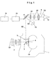
- Fig. 1 shows in schematic outlines a motion picture camera 1 with a rotating mirror aperture 3, which passes the guided via a camera lens 2 recording beam path S1 in an exposure phase to a moving in a film plane behind a picture window 4 motion picture film 10 for film image exposure or periodically deflects into an imaging beam S2.
- a fiberboard or a ground-mounted as a plano-convex lens focusing screen 5 is arranged, which is in the image plane, that is at the same distance to the rotating game screen 3, as the film plane in which the motion picture film 10 is intermittently transported.
- the imaging image imaged on the ground glass or fiber plate 5 in the exposure pauses of the motion picture film 10 is deflected by means of a DMD chip 6 either into a viewfinder beam path S3 or into a beam path S4 which leads to a light trap 13.
- the DMD chip 6 has a plurality of grid-like or matrix-shaped and by means of a driver circuit 15 quickly controllable micro-tilting mirror on a semiconductor substrate, depending on the drive by the driver circuit 15 between two end positions, which include an angle of for example 10 to 12 degrees to be pivoted.
- each micromirror corresponds to one image pixel, so that an image code supplied to the DMD chip 6 by the driver circuit 15 for driving the micromirrors initiates each individual micromirror and accordingly leaves it in the rest position or deflects a deflection position.
- the driver circuit 15 is connected to a control circuit 16 and this with an input keyboard, camera or image sensors or part of a microprocessor of the motion picture camera 1 for controlling camera functions and processing of input or sensory acquired data.
- the viewfinder eyepiece 8 includes a dial 81 in the form of a ground glass or fiber board, where a viewfinder image is displayed, which can be viewed via a viewfinder optics 82 from the eye 12 of a cameraman.
- the input field of the motion picture camera 1 contains a desired value transmitter or an actuator with which the duration of the deflection of the imaging beam S2 in the viewfinder beam S3 during the exposure pause of the motion picture film 10 and thus the coupled into the viewfinder beam S3 amount of light can be adjusted.
- the cameraman can hide stray light effects and light reflections in the recording image and in particular optimize the contrast extent in the recording image, with the stepless adjustment of the actuator, a stepless change of the duty cycle of the micromirror of the DMD chip 6 is connected to the micromirror between the viewfinder beam S3 and the Beam path S4 of the light trap 13 are pivoted.
- the driver circuit 15 drives the DMD chip 6 in such a way that during the image exposure pause, the micromirrors of the DMD chip 6 oscillate at high frequency between the viewfinder beam path S3 and the beam path S4 of the light trap 13 be and by changing the duty cycle by means of pulse width modulation in the viewfinder beam S3 on the one hand and the beam path S4 of the light trap 13 on the other hand mirrored amount of light of the imaging beam S2 is changed continuously.
- the DMD chip 6 is controlled by the control circuit 16 via the driver circuit 15 so that the viewfinder beam S3 during the exposure phase of the motion picture film 10 is interrupted synchronously, so that during the exposure phase of the motion picture film 10, the micromirrors of the DMD chip 6 deflect the imaging beam S2 into the beam path S4 of the light trap 13 and thus hide the light beams passing from the viewfinder optics 8 into the motion picture camera 1.
- Fig. 1 The arrangement according to Fig. 1 can in a similar manner to a Videoaustikungs Huawei 9 according to Fig. 2 be extended whose task and function will be explained in more detail below.
- Fig. 2 shows in accordance with the schematic representation of a film recording and imaging beam path according to Fig. 1 a motion picture camera 1 with a rotating mirror aperture 3, which transmits the recording beam path S1 guided via a camera lens 2 either to a motion picture film 10 moved behind a picture window 4 in a film plane or deflects it into an imaging beam path S2.
- a ground glass 5, on which a recording image is imaged in the exposure pauses of the motion picture film 10, and a beam splitter 13 are arranged, through which the imaging beam path S2 is split into a viewfinder beam path S3 and into a video beam path S5.
- the viewfinder beam path S3 is deflected either into a viewfinder eyepiece 8 or into a beam path S4 which leads to a first light trap 13.
- the first DMD chip 6 has a plurality of grid-like or matrix-shaped rapidly controllable micromirrors, which are pivoted between two end positions which enclose an angle of, for example, 10 to 12 degrees.
- the viewfinder eyepiece 8 includes a dial 81 in the form of a ground glass or fiber board, where a viewfinder image is displayed, which can be viewed via a S ucheroptik 82 from the eye 12 of a cameraman.
- a second DMD chip 7 is arranged, which likewise has a multiplicity of grid or matrix-shaped fast controllable micromirrors, which are pivoted between two end positions which enclose an angle of, for example, 10 to 12 degrees. and directs the video beam path S5 either to a Videoausspungs worn 9 or as a beam path S6 to a second light trap 14.
- the Videoaustikungs rose 9 includes a video optics 91, a video sensor 92 which converts the optical image of the beam path S5 in image signals, and a video electronics 93 which generates video signals from the image signals and these and optionally other control signals and data outputs to a personal computer and control and receives data signals from the personal computer. Since the video beam path S5 deflected from the imaging beam path S2 by means of the beam splitter 11 is guided over the second DMD chip 7, the recording image in the beam path to the video output device 9 is reversed, so that mirroring is performed electronically for correct image reproduction in the video output device 9.
- the video electronics 93 offer the possibility of connecting a monitor 94 on which the video images composed of the video signals can be viewed directly on the motion picture camera 1.
- the recording beam path S1 hits the opening sector (bright sector) of the rotating mirror shutter 3 and falls through the image window 4 onto the motion picture film 10 guided in the film channel, while during transport of the motion picture film 10 the image window 4 passes through the mirror surface of the rotating mirror shutter 3 is covered and the recording beam path S1 is deflected as imaging beam S2 to the ground glass or fiber plate 5, from where the imaging beam path S2 is divided via the beam splitter 11 in the viewfinder beam S3 and the video beam path S5.
- the viewfinder beam path S3 incident on the first DMD chip 6 is deflected via its micromirrors either to the viewfinder eyepiece 8 or as the beam path S4 to the first light trap 13.
- the beam splitter 11 derived from the video beam path S5 falls on the second DMD chip 7 and is deflected by this either the Videoaustikungs worn 9 or beam path S6 to the second light trap 14. Because of the periodic interruption of the recording beam path S1, the video output device 9 is given a diaphragm index signal from the motion picture camera, which corresponds to the respective exposure conditions of the video beam path S5 and thus to the exposure conditions on the video sensor 92, in addition to a mode select signal which specifies a desired exposure mode.
- Fig. 3 an alternative embodiment is shown, in which the beam splitter 11 between the first DMD chip 6 and the dial 81 of the viewfinder eyepiece 8 is arranged so that the imaging beam S2 either in the combined viewfinder and video beam paths S3 and S5 or the first light trap 13th is reflected.
- the amount of light deflected into the viewfinder and video beam paths S3 and S5 in this embodiment is the same or depends on the division ratio of the beam splitter 11, which can also be provided with different reflection or transmission ranges, so that a suitable image viewing through the eyepiece 8 and Video surveillance is guaranteed
- either the second DMD chip 7 may be omitted so that the video beam path corresponds to the viewfinder beam path, or a second DMD chip 7 will be connected in conjunction with a second light trap 14 as in the embodiment Fig. 2 intended.
Landscapes
- Physics & Mathematics (AREA)
- General Physics & Mathematics (AREA)
- Engineering & Computer Science (AREA)
- Multimedia (AREA)
- Signal Processing (AREA)
- Studio Devices (AREA)
- Mechanical Light Control Or Optical Switches (AREA)
- Apparatus For Radiation Diagnosis (AREA)
- Viewfinders (AREA)
Claims (10)
- Procédé pour la commande d'un trajet du faisceau d'imagerie (S2), dérivé d'un trajet d'un faisceau de prise de vue (S1) d'une caméra cinématographique (1), qui est interrompu périodiquement en fonction de la fréquence de prise de vue de la caméra cinématographique (1), caractérisé en ce que
pendant la pause d'exposition du film cinématographique (10), le trajet du faisceau d'imagerie (S2) est dévié ; au moyen d'un élément de commutation optique (6) avec une fréquence constante ou variable en tant que trajet du faisceau de viseur (S3) de la caméra cinématographique (1) vers un plan image à observer à travers un oculaire (8) ou vers un premier piège à lumière (13), et de manière synchrone à la phase d'exposition du film cinématographique (10) ; depuis le plan image à observer à travers l'oculaire vers le premier piège à lumière (13). - Procédé pour la commande d'un trajet de faisceau d'imagerie (S2), dérivé depuis un trajet du faisceau de prise de vue (S1) d'une caméra cinématographique (1), qui est interrompu périodiquement en fonction de la fréquence de prise de vue de la caméra cinématographique (1), caractérisé en ce que
pendant la pause d'exposition du film cinématographique (10), le trajet du faisceau d'imagerie (S2) est dévié, au moyen d'un élément de commutation optique (7) avec une fréquence constante ou variable en tant que trajet de faisceau vidéo (S5) de la caméra cinématographique (1), vers un dispositif de dérivation vidéo (9) comprenant un convertisseur optoélectronique (92) pour convertir le trajet du faisceau vidéo (S5) en signaux vidéo (VS), ou vers un second piège à lumière (14) et de manière synchrone à la phase d'exposition du film cinématographique (10), depuis le dispositif de dérivation vidéo (9) vers le second piège à lumière (14). - Procédé selon les revendications 1 et 2, caractérisé en ce que le trajet du faisceau d'imagerie (S2) est dévié, via un diviseur de faisceau (11), vers le trajet du faisceau de viseur (S3) avec un plan image à observer à travers l'oculaire (8), et vers le trajet du faisceau vidéo (S5) avec le convertisseur optoélectronique (92) pour convertir le trajet du faisceau vidéo (S2) en signaux vidéo (VS) de la caméra cinématographique (1).
- Procédé selon l'une au moins des revendications précédentes, caractérisé en ce que le rapport de cadence de la déviation du trajet du faisceau d'imagerie (S2) est modifié- à titre de trajet de faisceau de viseur (S3) vers le plan image à observer à travers l'oculaire (8) ou vers le premier piège à lumière (13), et/ou- à titre de trajet du faisceau vidéo (S5) vers le dispositif de dérivation vidéo (9) ou vers le second piège à lumière (14).
- Procédé selon la revendication 4, caractérisé en ce que le trajet du faisceau d'imagerie (S2) est dévié avec modulation en largeur d'impulsion vers le trajet du faisceau de viseur (S3) ou vers le premier piège à lumière (13) et/ou vers le trajet du faisceau vidéo (S5) ou le second piège à lumière (14).
- Appareil pour mettre en oeuvre le procédé selon l'une au moins des revendications précédentes, caractérisé par au moins une puce DMD (Digital Micromirror Device) (6, 7) agencée dans le trajet du faisceau d'imagerie (S2) de la caméra cinématographique (1) avec une pluralité de micro-miroirs agencés en formant une trame, lesquels sont susceptibles d'être pivotés sous une commande électronique, et dévient le trajet du faisceau d'imagerie (S2) incident- à titre de trajet du faisceau de viseur (S3) dans un plan image à observer à travers un oculaire (8) ou dans un trajet de faisceau (S4) d'un premier piège à lumière (13) et/ou- à titre de trajet de faisceau vidéo (S5) vers un dispositif de dérivation vidéo (9) avec un convertisseur optoélectronique (92) pour convertir le trajet du faisceau vidéo (S5) en signaux vidéo (VS), ou dans un trajet de faisceau (S6) d'un second piège à lumière (14).
- Appareil selon la revendication 6, caractérisé en ce que le trajet du faisceau d'imagerie (S2) est subdivisé, via un diviseur de faisceau (11), entre le trajet du faisceau de viseur (S3) et le trajet du faisceau vidéo (S5), en ce que les micro-miroirs d'une première puce DMD (6) agencée dans le trajet du faisceau de viseur (S3) réfléchissent le trajet du faisceau d'imagerie (S2) vers l'optique d'imagerie dans le trajet du faisceau de viseur (S3) avec un plan image à observer à travers un oculaire (8) ou vers le trajet de faisceau (S4) du premier piège à lumière (13), et en ce que les micro-miroirs de la seconde puce DMD (7) dévient le trajet du faisceau d'imagerie (S2) vers le trajet du faisceau vidéo (S5) avec un convertisseur optoélectronique (92) pour convertir le trajet du faisceau vidéo (S5) en signaux vidéo (VS), ou vers le trajet de faisceau (S6) du second piège à lumière (14).
- Appareil selon la revendication 6, caractérisé en ce que, entre une première puce DMD (6) et l'oculaire du viseur (8), un diviseur de faisceau est agencé, le diviseur de faisceau dévie le trajet du faisceau d'imagerie (S2) vers le trajet du faisceau de viseur (S3) et le trajet du faisceau vidéo (S5), et en ce que les micro-miroirs de la première puce DMD (6) réfléchissent le trajet du faisceau d'imagerie (S2) alternativement vers le diviseur de faisceau (11) ou vers le trajet de faisceau (S4) du premier piège à lumière (13).
- Appareil selon la revendication 8, caractérisé en ce que les micro-miroirs d'une deuxième puce DMD (7) dévient le trajet du faisceau vidéo (S5) vers un convertisseur optoélectronique (92) pour convertir le trajet du faisceau vidéo (S5) en signaux vidéo (VS) ou vers le trajet de faisceau (S6) du second piège à lumière (14).
- Appareil selon l'une au moins des revendications 6 a 9, caractérisé en ce que la première et/ou la seconde puce DMD (6, 7) est reliée, via un circuit pilote (15), à un circuit de commande (16) de la caméra cinématographique (1).
Applications Claiming Priority (2)
| Application Number | Priority Date | Filing Date | Title |
|---|---|---|---|
| DE102004016224A DE102004016224A1 (de) | 2004-03-26 | 2004-03-26 | Verfahren zur Steuerung eines aus einem Filmaufnahmestrahlengang einer Laufbildkamera abgezweigten Abbildungsstrahlenganges |
| PCT/DE2005/000498 WO2005096092A1 (fr) | 2004-03-26 | 2005-03-15 | Procede de commande d'un faisceau de reproduction devie d'un trajet optique de prise de vues d'une camera de prise de vues |
Publications (2)
| Publication Number | Publication Date |
|---|---|
| EP1728121A1 EP1728121A1 (fr) | 2006-12-06 |
| EP1728121B1 true EP1728121B1 (fr) | 2010-09-08 |
Family
ID=34966746
Family Applications (1)
| Application Number | Title | Priority Date | Filing Date |
|---|---|---|---|
| EP05736387A Expired - Fee Related EP1728121B1 (fr) | 2004-03-26 | 2005-03-15 | Procede de commande d'un faisceau de reproduction devie d'un trajet optique de prise de vues d'une camera de prise de vues |
Country Status (5)
| Country | Link |
|---|---|
| US (1) | US7903231B2 (fr) |
| EP (1) | EP1728121B1 (fr) |
| AT (1) | ATE480795T1 (fr) |
| DE (2) | DE102004016224A1 (fr) |
| WO (1) | WO2005096092A1 (fr) |
Families Citing this family (4)
| Publication number | Priority date | Publication date | Assignee | Title |
|---|---|---|---|---|
| JP2006071839A (ja) * | 2004-08-31 | 2006-03-16 | Olympus Corp | カメラ |
| US7544919B2 (en) | 2006-11-20 | 2009-06-09 | Red.Com, Inc. | Focus assist system and method |
| US9690168B2 (en) | 2006-11-20 | 2017-06-27 | Red.Com, Inc. | Focus assist system and method |
| DE102010023344A1 (de) | 2010-06-10 | 2012-01-19 | Arnold & Richter Cine Technik Gmbh & Co. Betriebs Kg | Kameraobjektiv und Kamerasystem |
Family Cites Families (12)
| Publication number | Priority date | Publication date | Assignee | Title |
|---|---|---|---|---|
| US3899791A (en) * | 1973-02-09 | 1975-08-12 | Maximilian Kerr Associates Inc | Photographic positioning and aligning grid |
| US4101916A (en) | 1976-08-02 | 1978-07-18 | Panavision, Incorporated | Illuminated ground glass for camera |
| EP0256051B1 (fr) * | 1986-01-20 | 1992-04-15 | Scanera S.C. | Dispositif de traitement d'image pour le controle de la fonction de transfert d'un systeme optique |
| US5255030A (en) * | 1990-08-31 | 1993-10-19 | Minolta Camera Kabushiki Kaisha | Camera |
| US5552845A (en) * | 1992-08-10 | 1996-09-03 | Olympus Optical Co., Ltd. | Camera |
| JPH07306444A (ja) * | 1994-03-16 | 1995-11-21 | Nikon Corp | カメラ |
| US5636001A (en) * | 1995-07-31 | 1997-06-03 | Collier; John | Digital film camera and digital enlarger |
| JPH1010633A (ja) | 1996-06-25 | 1998-01-16 | Olympus Optical Co Ltd | ファインダ装置 |
| JP4398017B2 (ja) * | 1998-10-07 | 2010-01-13 | オリンパス株式会社 | 測距装置 |
| JP2001177761A (ja) * | 1999-12-15 | 2001-06-29 | Minolta Co Ltd | デジタルカメラ |
| DE10020307A1 (de) * | 2000-04-17 | 2001-10-25 | Arnold & Richter Kg | Vorrichtung in abbildenden optischen Systemen einer Laufbild-Filmaufnahmekamera |
| DE10210327B4 (de) * | 2002-03-08 | 2012-07-05 | Arnold & Richter Cine Technik Gmbh & Co. Betriebs Kg | Digitale Laufbildkamera |
-
2004
- 2004-03-26 DE DE102004016224A patent/DE102004016224A1/de not_active Withdrawn
-
2005
- 2005-03-15 US US10/594,344 patent/US7903231B2/en not_active Expired - Fee Related
- 2005-03-15 WO PCT/DE2005/000498 patent/WO2005096092A1/fr active Application Filing
- 2005-03-15 EP EP05736387A patent/EP1728121B1/fr not_active Expired - Fee Related
- 2005-03-15 AT AT05736387T patent/ATE480795T1/de active
- 2005-03-15 DE DE502005010220T patent/DE502005010220D1/de active Active
Also Published As
| Publication number | Publication date |
|---|---|
| ATE480795T1 (de) | 2010-09-15 |
| EP1728121A1 (fr) | 2006-12-06 |
| US20070264005A1 (en) | 2007-11-15 |
| US7903231B2 (en) | 2011-03-08 |
| DE102004016224A1 (de) | 2005-10-06 |
| DE502005010220D1 (de) | 2010-10-21 |
| WO2005096092A1 (fr) | 2005-10-13 |
Similar Documents
| Publication | Publication Date | Title |
|---|---|---|
| DE69635891T2 (de) | Verbesserte optische kamera zur entfernungsmessung | |
| DE60209073T2 (de) | Bildprojektionsanzeigevorrichtung mit einem innen reflektierenden Abtastpolygonspiegel | |
| DE602004008360T2 (de) | Digitale Kamera mit entfernungsabhängigem Fokussierungsverfahren | |
| DE10155884A1 (de) | Bildsuchvorrichtung | |
| DE2738804A1 (de) | Verfahren und vorrichtung zur automatischen belichtungssteuerung in einer kamera | |
| EP2903250A1 (fr) | Procédé de prise de vue avec émission de lumière de marquage adaptative et appareil de prise de vue correspondant | |
| DE60300693T2 (de) | Objektiv mit Fokussierungsdetektor | |
| DE3328821A1 (de) | Autofokus fuer mikroskope | |
| WO2001027683A2 (fr) | Ensemble dans lequel de la lumiere provenant d'une source lumineuse est dirigee sur une surface | |
| EP1728121B1 (fr) | Procede de commande d'un faisceau de reproduction devie d'un trajet optique de prise de vues d'une camera de prise de vues | |
| DE10028233A1 (de) | Farbkameraanordnung mit einem photosensitiven,Iv ladungsgekoppelten Bildwandler (CCD) | |
| DE4143221A1 (de) | Optisches system fuer einen projektor | |
| DE2549760A1 (de) | Entfernungsmesseinrichtung zur automatischen fokussierung optischer geraete | |
| DE602004006752T2 (de) | Autofokussystem | |
| DE69628806T2 (de) | Kamera mit variabler Ablenkung | |
| DE10010443B4 (de) | Optisches Suchersystem | |
| EP1259846B1 (fr) | Procede et dispositif de reglage d'un appareil photographique | |
| DE10027371A1 (de) | Optisches System zur Drehung von Aufnahmebildern einer Laufbildkamera um die optische Achse | |
| DE2041237C3 (de) | Automatische Scha rf einstellvorrichtung für Kameras oder dergleichen | |
| DE2201092B2 (de) | Einrichtung zur Bestimmung der relativen Lage der Ebene maximaler Amplitude einer Ortsfrequenz | |
| CH510884A (de) | Optisches Beobachtungsgerät | |
| DE102019204075B4 (de) | Vorrichtung mit einer Multiaperturabbildungsvorrichtung zur Erzeugung einer Tiefenkarte | |
| EP1389737B1 (fr) | Viseur à grande angle avec réseau de microobturateurs commutables | |
| EP1754106B1 (fr) | Dispositif de surimposition d'informations dans la trajectoire du faisceau du viseur d'une camera | |
| DE19907345B4 (de) | Vorrichtung zum Abbilden eines als Raster von Bildpunkten darstellbaren Bildes auf einem Schirm |
Legal Events
| Date | Code | Title | Description |
|---|---|---|---|
| PUAI | Public reference made under article 153(3) epc to a published international application that has entered the european phase |
Free format text: ORIGINAL CODE: 0009012 |
|
| 17P | Request for examination filed |
Effective date: 20060926 |
|
| AK | Designated contracting states |
Kind code of ref document: A1 Designated state(s): AT DE GB |
|
| RIN1 | Information on inventor provided before grant (corrected) |
Inventor name: HAUBMANN, MICHAEL |
|
| DAX | Request for extension of the european patent (deleted) | ||
| RBV | Designated contracting states (corrected) |
Designated state(s): AT DE GB |
|
| 17Q | First examination report despatched |
Effective date: 20091019 |
|
| GRAP | Despatch of communication of intention to grant a patent |
Free format text: ORIGINAL CODE: EPIDOSNIGR1 |
|
| GRAS | Grant fee paid |
Free format text: ORIGINAL CODE: EPIDOSNIGR3 |
|
| GRAA | (expected) grant |
Free format text: ORIGINAL CODE: 0009210 |
|
| AK | Designated contracting states |
Kind code of ref document: B1 Designated state(s): AT DE GB |
|
| REG | Reference to a national code |
Ref country code: GB Ref legal event code: FG4D Free format text: NOT ENGLISH |
|
| REF | Corresponds to: |
Ref document number: 502005010220 Country of ref document: DE Date of ref document: 20101021 Kind code of ref document: P |
|
| PLBE | No opposition filed within time limit |
Free format text: ORIGINAL CODE: 0009261 |
|
| STAA | Information on the status of an ep patent application or granted ep patent |
Free format text: STATUS: NO OPPOSITION FILED WITHIN TIME LIMIT |
|
| 26N | No opposition filed |
Effective date: 20110609 |
|
| REG | Reference to a national code |
Ref country code: DE Ref legal event code: R097 Ref document number: 502005010220 Country of ref document: DE Effective date: 20110609 |
|
| PGFP | Annual fee paid to national office [announced via postgrant information from national office to epo] |
Ref country code: GB Payment date: 20130318 Year of fee payment: 9 Ref country code: DE Payment date: 20130118 Year of fee payment: 9 |
|
| PGFP | Annual fee paid to national office [announced via postgrant information from national office to epo] |
Ref country code: AT Payment date: 20130318 Year of fee payment: 9 |
|
| REG | Reference to a national code |
Ref country code: DE Ref legal event code: R119 Ref document number: 502005010220 Country of ref document: DE |
|
| REG | Reference to a national code |
Ref country code: AT Ref legal event code: MM01 Ref document number: 480795 Country of ref document: AT Kind code of ref document: T Effective date: 20140315 |
|
| GBPC | Gb: european patent ceased through non-payment of renewal fee |
Effective date: 20140315 |
|
| REG | Reference to a national code |
Ref country code: DE Ref legal event code: R119 Ref document number: 502005010220 Country of ref document: DE Effective date: 20141001 |
|
| PG25 | Lapsed in a contracting state [announced via postgrant information from national office to epo] |
Ref country code: DE Free format text: LAPSE BECAUSE OF NON-PAYMENT OF DUE FEES Effective date: 20141001 Ref country code: GB Free format text: LAPSE BECAUSE OF NON-PAYMENT OF DUE FEES Effective date: 20140315 |
|
| PG25 | Lapsed in a contracting state [announced via postgrant information from national office to epo] |
Ref country code: AT Free format text: LAPSE BECAUSE OF NON-PAYMENT OF DUE FEES Effective date: 20140315 |