EP1727679B1 - Method for identifying a single panel comprising a printed image of defective quality on printed material comprising several panels - Google Patents
Method for identifying a single panel comprising a printed image of defective quality on printed material comprising several panels Download PDFInfo
- Publication number
- EP1727679B1 EP1727679B1 EP05717040A EP05717040A EP1727679B1 EP 1727679 B1 EP1727679 B1 EP 1727679B1 EP 05717040 A EP05717040 A EP 05717040A EP 05717040 A EP05717040 A EP 05717040A EP 1727679 B1 EP1727679 B1 EP 1727679B1
- Authority
- EP
- European Patent Office
- Prior art keywords
- image
- printing substrate
- quality
- panel
- taken
- Prior art date
- Legal status (The legal status is an assumption and is not a legal conclusion. Google has not performed a legal analysis and makes no representation as to the accuracy of the status listed.)
- Active
Links
Images

Classifications
-
- B—PERFORMING OPERATIONS; TRANSPORTING
- B41—PRINTING; LINING MACHINES; TYPEWRITERS; STAMPS
- B41F—PRINTING MACHINES OR PRESSES
- B41F33/00—Indicating, counting, warning, control or safety devices
- B41F33/0036—Devices for scanning or checking the printed matter for quality control
Definitions
- the invention relates to methods for identifying a single benefit with a print image of faulty quality on a substrate with multiple benefits according to the preamble of claim 1 or 11.
- the DE 200 10 920 U1 and the EP 11 67 036 A1 are a printing machine, in particular a sheetfed offset press, known in which for detecting the quality of a printing material arranged on an image capture device detects the substrate and an evaluation device connected to the image acquisition device compares the recorded by the image capture device image of the substrate with a reference image, wherein the substrate with a A plurality of identical printed images is printed and the evaluation evaluates only a subset of the printed images from the image of the printing material, wherein the evaluation outputs a signal to a counter for registration of the subset in accordance with the evaluated subset with the reference image.
- a method of identifying a single benefit with a print image of defective quality on a multi-use substrate wherein an inspection system with a camera captures an image of the substrate and processes data of the captured image in an image processing system, the image processing system capturing the data of the image processing system recorded image with a single benefit on the substrate compares data record.
- an image inspection system for a printing press in which the printing material printed in the user recorded by an image pickup device and the image signals obtained are processed in a downstream image processing, wherein the image pickup device is arranged according to the image signals controllable printing device, through which at designated locations of the printing material markings can be generated for the identification of identified as defective areas, as a result of which incorrectly printed benefits are ausschleusbar in a suitably trained device further processing.
- the invention has for its object to provide methods for identifying a single benefit with a print image of faulty quality on a substrate with multiple benefits, where the identification of the print image of defective quality benefits without the aid of a printed Referenzbedruckstoffes takes place and in which for the identification of individual erroneous benefits and for obtaining a record for performing this identification a rational production process results.
- a printing material printed by a printing press in particular a sheet
- the benefit with the print image of faulty quality is separable in a subsequent process of the printing process, so that all other benefits can be fed with a print image of good quality of the intended use.
- a single benefit with a printed image of defective quality is uniquely identifiable. It is very advantageous that each of the proposed methods is capable of identifying individual benefits of any shape and orientation on the substrate.
- a set-up phase of the printing press remains unaffected by the process for identifying a single benefit with a print image of faulty quality, so that in the setup phase of the printing press, an additional step is not required, the z. B. could consist in an evaluation of a specially prepared Einrichtebogens.
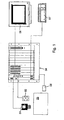
- a suitable in particular for a print image inspection inspection system has according to its schematic representation in the Fig. 1 a camera 01, z. B. one or more coupled color line cameras 01 or a color area camera 01, which receives an illuminated by a lighting device 02 image of a preferably formed as a sheet 03 substrate 03 after the z. B. made of paper substrate 03 from a printing press, z.
- a rotary printing machine in particular a sheet offset rotary printing machine, has been printed with at least one printed image.
- the printing material 03 is printed in its passage through the printing press in multi-color printing, so involved in the production of the printed product several superimposed to be printed, differing in hue of the respective printing ink color separations.
- the image taken by the camera 01 forms at least part of the printing material 03.
- the output of the result is z. B. on a connected to the data processing image processing system 04 monitor 06.
- inputs, z. B. the image processing system 04 for its calculations necessarily be notified parameters are entered via a connected to the image processing system 04 keyboard 07.
- the substrate 03 here z. B. the sheet 03 is printed in its passage through the printing press in the whotik and has according to the Fig. 2 several individual benefits 09 in a composite.
- the individual benefits 09 may be repetitive, z. B. also identical print motifs, preferably structured, z. B. grid-like, ie arranged in rows and columns, on the sheet 03, wherein arranged on the sheet 03 benefits 09 in the preferred embodiment does not have to cover the entire printable area of the sheet 03.
- the benefits 09 arranged on the sheet 03 are identical in their contours, or for the respective contours to be substantially rectangular, or for those arranged on the sheet 03 Benefits 09 are adjacent to each other seamlessly or that the benefits 09 are arranged on the sheet 03 in a regular structure, ie a grid with a fixed orientation.
- the sheet 03 resulting on the sheet 03 at least one area 11, z.
- the printed sheet 03 further processing process step is removed. Therefore, the image photographically taken by the color line camera 01 or the color area camera 01 from the sheet 03 in the image processing system 04 is preferably evaluated only with respect to the utility 09 arranged on the sheet 03, so that the area 11 or edge 11 located on the sheet 03 outside the utility 09 one of the quality of the printed image mitigating error is not evaluated.
- the selective evaluation of the sheet 03 with respect to at least one of the quality of the printed image mitigating error eg. As a color error, contamination or any other before or especially during the printing process the bow 03 added error is designed such that it is determined which arranged on the sheet 03 benefits 09 of the color line camera 01 or the color surface camera 01 detected error is to be assigned.
- information about the location of the detected error with respect to the surface predetermined by the sheet 03, in particular its printable surface is preferably initially determined in the image processing system 04 by a corresponding evaluation of the data correlated with the recorded image, so that the quality of the printed image is reduced Error z. B. is localized in its coordinates, and then of the printed on the sheet 03 benefits 09 of the benefits 09 is identified within the contour of the location of the detected error is located.
- a single benefit 09 is identified by the fact that the image processing system 04, so to speak, hangs up a template in its data processing process steps on the image taken by the color line camera 01 or the color area camera 01 from the sheet 03, the template consisting of an electronically generated data record, this data record is not taken from a photographically recorded image and in particular is not obtained within the printing press, but z. B. stored in a pre-press data is taken.
- the template forming the record is z. B. generated with a CAD system (computer-aided design) and a memory z. B. fed in the prepress, this record information about position, shape or shape or size, z. B. diameter, the individual arranged on the sheet 03 benefits 09 contains or wherein this information is at least removed from this record.
- the information can also refer to the arrangement of individual benefits 09 in the totality of all benefits 09 and thus provide information about the location of a single benefit 09 relative to one or more other benefits 09.
- the shape of a benefit 09 characterizes its type or type, e.g. As circle, rectangle or any other geometric shape.
- the data set is generated in conjunction with a production of a die for separating the benefits 09 from the sheet 03 and fed to the image processing system 04. This measure is advantageous because it makes use of an already existing data record, so that additional expenditure for generating this data record does not arise.
- the template forming the record is a fixed reference between a detected by the color line camera 01 or the color area camera 01 error to a single use 09 on the sheet 03 produced by the information z. B.
- the arrangement, shape or size of the individual arranged on the sheet 03 benefits 09 is superimposed on the data from the color line camera 01 or the color area camera 01 image or at least the information on the location of the detected error for the purpose of comparison. Because with the help of the template forming the record can now z. B. by the image processing system 04 by comparing the information to the determined location of the error with the information on the arrangement, shape or size of the individual arranged on the sheet 03 benefits 09 are clearly identified, which arranged on the sheet 03 benefits 09 a on the Sheet 03 is associated with detected and localized error.
- a benefit 09 identified in such a way with regard to a fault detected by the color line camera 01 or the color area camera 01 can be detected by a user.
- the identified on the sheet 03 benefits 09 within the contour of which is detected by the color line camera 01 or the color surface camera 01 error is separable from the other benefits 09 in a process subsequent to the actual printing process processing by arranged on the sheet 03 benefits 09 z , B. are punched out with a punch and the detected error having, preferably marked benefits 09 z. B. is extracted by discharge.
- all the benefits arranged on the sheet 03 are 09 except for the marked ones Benefit 09 of the intended use fed, which is particularly advantageous for high-quality printed products.
Abstract
Description
Die Erfindung betrifft Verfahren zur Identifikation eines einzelnen Nutzens mit einem Druckbild von fehlerhafter Qualität auf einem Bedruckstoff mit mehreren Nutzen gemäß dem Oberbegriff des Anspruchs 1 oder 11.The invention relates to methods for identifying a single benefit with a print image of faulty quality on a substrate with multiple benefits according to the preamble of
Durch die
Durch die
Durch den Fachartikel von Dieter Kleeberg, "Die vernetzte Druckerei", in der Beilage zur Kundenzeitschrift KBA Report Nr. 14, Koenig & Bauer AG, Würzburg 2000, Seiten 4, 6, 7, ist bekannt, Positionsdaten der Weiterverarbeitung und Daten zur Inline-Qualitätskontrolle durch ein einheitliches Dateiformat in einem Datensatz zusammenzustellen (CIP3-PPF-Dateien). Durch dieses Vorgehen ist ein Datensatz zur Identifikation einzelner fehlerhafter Nutzen und zur Weiterverarbeitung nur einmal zu erstellen.By the article by Dieter Kleeberg, "The networked printing", in the supplement to Customer magazine KBA Report No. 14, Koenig & Bauer AG, Würzburg 2000, pages 4, 6, 7, is known to compile positioning data of further processing and data for inline quality control by a single file format in a record (CIP3-PPF files). Through this procedure, a data record for the identification of individual erroneous uses and for further processing must be created only once.
Durch die
Durch die nachveröffentlichte
Der Erfindung liegt die Aufgabe zugrunde, Verfahren zur Identifikation eines einzelnen Nutzens mit einem Druckbild von fehlerhafter Qualität auf einem Bedruckstoff mit mehreren Nutzen zu schaffen, bei denen die Identifikation des das Druckbild von fehlerhafter Qualität aufweisenden Nutzens ohne Zuhilfenahme eines gedruckten Referenzbedruckstoffes erfolgt und bei denen sich für die Identifikation einzelner fehlerhafter Nutzen und für eine Beschaffung eines Datensatzes zur Durchführung dieser Identifikation ein rationeller Herstellungsablauf ergibt.The invention has for its object to provide methods for identifying a single benefit with a print image of faulty quality on a substrate with multiple benefits, where the identification of the print image of defective quality benefits without the aid of a printed Referenzbedruckstoffes takes place and in which for the identification of individual erroneous benefits and for obtaining a record for performing this identification a rational production process results.
Die Aufgabe wird erfindungsgemäß durch die Merkmale des Anspruchs 1 oder 11 gelöst.The object is achieved by the features of
Die mit der Erfindung erzielbaren Vorteile bestehen insbesondere darin, dass ein von einer Druckmaschine bedruckter Bedruckstoff, insbesondere ein Bogen, mit mehreren Nutzen nicht als Ausschuss zu behandeln ist, wenn ein einzelner Nutzen des Bedruckstoffes ein Druckbild von fehlerhafter Qualität aufweist. Der Nutzen mit dem Druckbild von fehlerhafter Qualität ist in einem dem Druckprozess nachgeordneten Arbeitsschritt separierbar, sodass alle anderen Nutzen mit einem Druckbild von guter Qualität der zugedachten Verwendung zugeführt werden können. Mit den vorgeschlagenen Verfahren ist ein einzelner Nutzen mit einem Druckbild von fehlerhafter Qualität eindeutig identifizierbar. Es ist sehr vorteilhaft, dass jedes der vorgeschlagenen Verfahren geeignet ist, einzelne Nutzen beliebiger Form und beliebiger Orientierung auf dem Bedruckstoff zu identifizieren. Eine Einrichtephase der Druckmaschine bleibt von dem Verfahren zur Identifikation eines einzelnen Nutzens mit einem Druckbild von fehlerhafter Qualität unberührt, sodass in der Einrichtephase der Druckmaschine ein zusätzlicher Arbeitsschritt nicht erforderlich ist, der z. B. in einer Auswertung eines speziell anzufertigenden Einrichtebogens bestehen könnte.The advantages which can be achieved with the invention are, in particular, that a printing material printed by a printing press, in particular a sheet, is not to be treated as scrap with several benefits if a single use of the printing material has a printed image of faulty quality. The benefit with the print image of faulty quality is separable in a subsequent process of the printing process, so that all other benefits can be fed with a print image of good quality of the intended use. With the proposed methods, a single benefit with a printed image of defective quality is uniquely identifiable. It is very advantageous that each of the proposed methods is capable of identifying individual benefits of any shape and orientation on the substrate. A set-up phase of the printing press remains unaffected by the process for identifying a single benefit with a print image of faulty quality, so that in the setup phase of the printing press, an additional step is not required, the z. B. could consist in an evaluation of a specially prepared Einrichtebogens.
Ausführungsbeispiele der Erfindung sind in den Zeichnungen dargestellt und werden im Folgenden näher beschrieben.Embodiments of the invention are illustrated in the drawings and will be described in more detail below.
Es zeigen:
- Fig. 1
- eine schematische Darstellung eines Inspektionssystems;
- Fig. 2
- einen Bogen mit mehreren Nutzen.
- Fig. 1
- a schematic representation of an inspection system;
- Fig. 2
- a bow with several benefits.
Ein insbesondere für eine Druckbildkontrolle geeignetes Inspektionssystem weist gemäß seiner schematischen Darstellung in der
Das von der Kamera 01 aufgenommene Bild bildet zumindest einen Teil des Bedruckstoffes 03 ab. Von der Kamera 01 aus der Aufnahme des Bildes ermittelte Daten, die z. B. mit Amplitudenwerten einzelner Farbkanäle korrelieren, werden in einem Bildverarbeitungssystem 04 verarbeitet. Die Ausgabe des Ergebnisses erfolgt z. B. auf einem mit dem Daten verarbeitenden Bildverarbeitungssystem 04 verbundenen Monitor 06. Eingaben, z. B. dem Bildverarbeitungssystem 04 für seine Berechnungen notwendigerweise mitzuteilende Parameter, werden über eine an das Bildverarbeitungssystem 04 angeschlossene Tastatur 07 eingegeben.The image taken by the
Der Bedruckstoff 03, hier z. B. der Bogen 03, wird bei seinem Durchlauf durch die Druckmaschine im Nutzendruck bedruckt und weist gemäß der
Wenn mehrere Nutzen 09 beliebiger Form, d. h. beliebiger Gestalt, und auch beliebiger Orientierung auf dem Bogen 03 angeordnet sind, ergibt sich auf dem Bogen 03 zumindest ein Bereich 11, z. B. ein Rand 11, in welchem sich ein die Qualität des Druckbildes mindernder, insbesondere vom Druck resultierender Fehler nicht nachteilig auswirkt, weil dieser Bereich 11 oder Rand 11 in einem dem Druck nachfolgenden, den bedruckten Bogen 03 weiter verarbeitenden Prozessschritt entfernt wird. Daher wird das von der Farbzeilenkamera 01 oder der Farbflächenkamera 01 vom Bogen 03 fotografisch aufgenommene Bild im Bildverarbeitungssystem 04 vorzugsweise nur hinsichtlich der auf dem Bogen 03 angeordneten Nutzen 09 ausgewertet, sodass der auf dem Bogen 03 außerhalb der Nutzen 09 befindliche Bereich 11 oder Rand 11 hinsichtlich eines die Qualität des Druckbildes mindernden Fehlers nicht ausgewertet wird.If
Die selektive Auswertung des Bogens 03 hinsichtlich mindestens eines die Qualität des Druckbildes mindernden Fehlers, z. B. eines Farbfehlers, einer Verschmutzung oder irgendeines anderen vor oder insbesondere während des Druckprozesses dem Bogen 03 zugefügten Fehlers, ist derart ausgebildet, dass ermittelt wird, welchem der auf dem Bogen 03 angeordneten Nutzen 09 der von der Farbzeilenkamera 01 oder der Farbflächenkamera 01 detektierte Fehler zuzuordnen ist. Dazu wird in dem Bildverarbeitungssystem 04 durch eine entsprechende Auswertung der mit dem aufgenommenen Bild korrelierenden Daten vorzugsweise zunächst eine Information zum Ort des detektierten Fehlers mit Bezug auf die vom Bogen 03 vorgegebene Fläche, insbesondere dessen bedruckbare Fläche, ermittelt, sodass der die Qualität des Druckbildes mindernde Fehler z. B. in seinen Koordinaten lokalisiert wird, und dann wird von den auf den Bogen 03 gedruckten Nutzen 09 derjenige Nutzen 09 identifiziert, innerhalb dessen Kontur der Ort des detektierten Fehlers liegt.The selective evaluation of the
Ein einzelner Nutzen 09 wird dadurch identifiziert, dass das Bildverarbeitungssystem 04 in seinen Daten verarbeitenden Prozessschritten auf das von der Farbzeilenkamera 01 oder der Farbflächenkamera 01 vom Bogen 03 aufgenommene Bild sozusagen eine Schablone auflegt, wobei die Schablone aus einem elektronischen generierten Datensatz besteht, wobei dieser Datensatz nicht einem fotografisch aufgenommenen Bild entnommen und insbesondere nicht innerhalb der Druckmaschine gewonnen wird, sondern z. B. in einer Druckvorstufe gespeicherten Daten entnommen ist. Der die Schablone bildende Datensatz wird z. B. mit einem CAD-System (computer-aided design) erzeugt und einem Speicher z. B. in der Druckvorstufe zugeführt, wobei dieser Datensatz eine Information zur Position, Form bzw. Gestalt oder Größe, z. B. Durchmesser, der einzelnen auf dem Bogen 03 angeordneten Nutzen 09 enthält oder wobei diese Information diesem Datensatz zumindest entnehmbar ist. Statt auf eine absolute Position kann sich die Information auch auf die Anordnung einzelner Nutzen 09 in der Gesamtheit aller Nutzen 09 beziehen und damit über die Lage eines einzelnen Nutzens 09 relativ zu einem oder mehrerer anderer Nutzen 09 Auskunft geben. Die Form eines Nutzens 09 charakterisiert dessen Typ oder Art, z. B. Kreis, Rechteck oder eine andere beliebige geometrische Gestalt. In der bevorzugten Ausführung wird der Datensatz in Verbindung mit einer Herstellung von einer Stanzform zum Separieren der Nutzen 09 aus dem Bogen 03 generiert und dem Bildverarbeitungssystem 04 zugeleitet. Diese Maßnahme ist vorteilhaft, weil dadurch auf einen ohnehin vorliegenden Datensatz zurückgegriffen wird, sodass zusätzlicher Aufwand zur Generierung dieses Datensatzes nicht entsteht. Wenn auf dem Bogen 03 in der Gesamtheit aller dort angeordneten Nutzen 09 ein einzelner Nutzen 09 mit einer sich vorzugsweise signifikant von den anderen Nutzen 09 unterscheidender Form oder Gestalt angeordnet ist, kann bei Ermittlung eines die Qualität des Druckbildes mindernden Fehlers an diesem andersartigen Nutzen 09 direkt auf den auf den Bogen 03 bezogenen Fehlerort geschlossen werden, weil sich dieser andersartige Nutzen 09 in einem festen Verbund mit den anderen auf dem Bogen 03 angeordneten Nutzen 09 befindet.A
Mit dem die Schablone bildenden Datensatz ist ein fester Bezug zwischen einem von der Farbzeilenkamera 01 oder der Farbflächenkamera 01 detektierten Fehler zu einem einzelnen Nutzen 09 auf dem Bogen 03 herstellbar, indem die Information z. B. zur Anordnung, Gestalt oder Größe der einzelnen auf dem Bogen 03 angeordneten Nutzen 09 den Daten von dem von der Farbzeilenkamera 01 oder der Farbflächenkamera 01 aufgenommenen Bild oder zumindest der Information zum Ort des detektierten Fehlers zum Zweck eines Vergleichs überlagert wird. Denn mit Hilfe des die Schablone bildenden Datensatzes kann nun z. B. von dem Bildverarbeitungssystem 04 durch einen Vergleich der Information zum ermittelten Ort des Fehlers mit der Information zur Anordnung, Gestalt oder Größe der einzelnen auf dem Bogen 03 angeordneten Nutzen 09 eindeutig festgestellt werden, welchem der auf dem Bogen 03 angeordneten Nutzen 09 ein auf dem Bogen 03 detektierter und lokalisierter Fehler zugeordnet ist.With the template forming the record is a fixed reference between a detected by the
Ein derart hinsichtlich eines von der Farbzeilenkamera 01 oder der Farbflächenkamera 01 detektierten Fehlers identifizierter Nutzen 09 kann von einer z. B. von dem Bildverarbeitungssystem 04 gesteuerten Markiereinrichtung 08 z. B. durch Auftragen einer Nummerierung oder einer andersartigen Kennzeichnung markiert oder auch auf dem Monitor 06 angezeigt werden, sodass die Markierung des betreffenden Nutzens 09 mit einem Druckbild von fehlerhafter Qualität auch beispielsweise durch das Bedienpersonal der Druckmaschine erfolgen kann.A
Der auf dem Bogen 03 identifizierte Nutzen 09, innerhalb dessen Kontur der von der Farbzeilenkamera 01 oder der Farbflächenkamera 01 detektierte Fehler liegt, ist in einem dem eigentlichen Druckprozess nachfolgenden Verarbeitungsschritt von den übrigen Nutzen 09 separierbar, indem die auf dem Bogen 03 angeordneten Nutzen 09 z. B. mit einem Stanzwerkzeug ausgestanzt werden und der den detektierten Fehler aufweisende, vorzugsweise markierte Nutzen 09 z. B. durch Ausschleusung extrahiert wird. Im Ergebnis sind somit alle auf dem Bogen 03 angeordneten Nutzen 09 mit Ausnahme der markierten Nutzen 09 der zugedachten Verwendung zuführbar, was insbesondere für hochwertige Druckerzeugnisse von Vorteil ist.The identified on the
- 0101
- Kamera, Farbzeilenkamera, FarbflächenkameraCamera, color line camera, color area camera
- 0202
- Beleuchtungseinrichtunglighting device
- 0303
- Bedruckstoff, BogenSubstrate, sheet
- 0404
- BildverarbeitungssystemImage processing system
- 0505
- --
- 0606
- Monitormonitor
- 0707
- Tastaturkeyboard
- 0808
- Markiereinrichtungmarking
- 0909
- NutzenUse
- 1010
- --
- 1111
- Bereich, RandArea, edge
Claims (17)
- A method for identifying an individual panel (09) with a printed image of defective quality on a printing substrate (03) with several panels (09), wherein a photographic image is taken at least of part of the printing substrate (03) and data which correlate with the taken image are checked to see whether a defect which lessens the quality of the printed image is present on the printing substrate (03), wherein information on the location of the panel (09) having the defect which lessens the quality of the printed image is ascertained with reference to the printing substrate (03), characterised in that the location of the panel (09) having the defect which lessens the quality of the printed image is ascertained by a comparison of the data which correlate with the taken image with an electronically generated data set with information on the arrangement, form or size of the individual panels (09) arranged on the printing substrate (03).
- A method according to Claim 1, characterised in that the electronically generated data set with information on the arrangement, form or size of the individual panels arranged on the printing substrate (03) is taken from data stored in a pre-press stage.
- A method according to Claim 1, characterised in that the electronically generated data set with information on the arrangement, form or size of the individual panels arranged on the printing substrate (03) which is taken from stored data is produced in a process step which processes the printing substrate (03).
- A method according to Claim 1, characterised in that the electronically generated data set with information on the arrangement, form or size of the individual panels arranged on the printing substrate (03) which is taken from stored data is obtained in conjunction with the production of a cutting die for separating the panels (09) from the printing substrate (03).
- A method according to Claim 1, characterised in that the electronically generated data set with information on the arrangement, form or size of the individual panels arranged on the printing substrate (03) which is taken from stored data is produced with a CAD system.
- A method according to Claim 1, characterised in that the panel (09) having the defect which lessens the quality of the printed image which is detected is marked.
- A method according to Claim 1, characterised in that numbering or another marking is applied to the panel (09) having the defect which lessens the quality of the printed image which is detected.
- A method according to Claim 1, characterised in that the panel (09) having the defect which lessens the quality of the printed image which is detected is displayed on a monitor (06).
- A method according to Claim 1, characterised in that the panel (09) having the defect which lessens the quality of the printed image which is detected is separated from the other panels (09) in a processing step following the printing process.
- A method according to Claim 1, characterised in that the panel (09) having the defect which lessens the quality of the printed image which is detected is cut out from the printing substrate (03).
- A method for identifying an individual panel (09) with a printed image of defective quality on a printing substrate (03) with several panels (09), wherein an inspection system with a camera (01) takes an image of the printing substrate (03) and data of the taken image are processed in an image processing system (04), the image processing system (04) comparing the data of the taken image with a data set relating to individual panels (09) on the printing substrate (03), characterised in that the image processing system (04) performs the comparison with a data set on the form of the individual panels (09) on the printing substrate (03) which is taken from stored data, the data set originating from the production of a punching die for separating the panels (09) from the printing substrate (03).
- A method according to Claim 11, characterised in that the image taken of the printing substrate (03) is superimposed on an image obtained from the data set in the image processing system (04).
- A method according to Claim 11, characterised in that the image processing system (04) compares the data of the taken image with a data set on the position of the individual panels (09) on the printing substrate (03).
- A method according to Claim 11, characterised in that a panel (09) which does not agree with the form specified by the data set is marked by a marking means (08).
- A method according to Claim 14, characterised in that the marking means (08) is controlled by the image processing system (04).
- A method according to Claim 14, characterised in that the marking means (08) applies numbering or another marking to the panel (09) having a printed image of defective quality.
- A method according to Claim 11, characterised in that a panel (09) which does not agree with the form specified by the data set is displayed on a monitor (06).
Applications Claiming Priority (3)
| Application Number | Priority Date | Filing Date | Title |
|---|---|---|---|
| DE200410014549 DE102004014549B3 (en) | 2004-03-23 | 2004-03-23 | Defective quality printed image copy identifying method for print substrate, involves determining location of copy containing defect by comparing data, correlating with image, to data record concerning arrangement and form of copy |
| DE200410029140 DE102004029140A1 (en) | 2004-06-17 | 2004-06-17 | Defective quality printed image copy identifying method for print substrate, involves determining location of copy containing defect by comparing data, correlating with image, to data record concerning arrangement and form of copy |
| PCT/EP2005/051163 WO2005092620A2 (en) | 2004-03-23 | 2005-03-15 | Method for identifying a single panel comprising a printed image of defective quality on printed material comprising several panels |
Publications (2)
| Publication Number | Publication Date |
|---|---|
| EP1727679A2 EP1727679A2 (en) | 2006-12-06 |
| EP1727679B1 true EP1727679B1 (en) | 2008-10-01 |
Family
ID=34961308
Family Applications (1)
| Application Number | Title | Priority Date | Filing Date |
|---|---|---|---|
| EP05717040A Active EP1727679B1 (en) | 2004-03-23 | 2005-03-15 | Method for identifying a single panel comprising a printed image of defective quality on printed material comprising several panels |
Country Status (6)
| Country | Link |
|---|---|
| US (1) | US7710595B2 (en) |
| EP (1) | EP1727679B1 (en) |
| AT (1) | ATE409584T1 (en) |
| DE (1) | DE502005005538D1 (en) |
| ES (1) | ES2310814T3 (en) |
| WO (1) | WO2005092620A2 (en) |
Cited By (3)
| Publication number | Priority date | Publication date | Assignee | Title |
|---|---|---|---|---|
| WO2020216521A1 (en) | 2019-04-26 | 2020-10-29 | Koenig & Bauer Ag | Sheet-processing machine and method for inspecting a sheet |
| DE102019110854A1 (en) * | 2019-04-26 | 2020-10-29 | Koenig & Bauer Ag | Method for inspecting at least one sheet and devices for inspecting at least one sheet |
| DE102021114252A1 (en) | 2021-06-02 | 2022-12-08 | Koenig & Bauer Ag | Process for ejecting and/or removing faulty panels |
Families Citing this family (3)
| Publication number | Priority date | Publication date | Assignee | Title |
|---|---|---|---|---|
| DE102006015828A1 (en) * | 2006-04-03 | 2007-10-04 | Man Roland Druckmaschinen Ag | Image inspection system for e.g. sheet-fed offset press, has sorting device, where data, which are stored in memory and obtained by image processing algorithm, are stored in another memory for analysis by algorithm |
| US20130087059A1 (en) * | 2011-10-06 | 2013-04-11 | Applied Vision Corporation | System and method for detecting decorator wheel blanket defects |
| DE102015203358B4 (en) | 2015-02-25 | 2016-09-29 | Koenig & Bauer Ag | Method for evaluating a plurality of printed products each having at least one print image with respect to their respective further processing capability |
Family Cites Families (9)
| Publication number | Priority date | Publication date | Assignee | Title |
|---|---|---|---|---|
| DE59208384D1 (en) * | 1991-08-12 | 1997-05-28 | Koenig & Bauer Ag | Quality control of an image template e.g. B. a printed pattern |
| DE4432371B4 (en) | 1994-09-12 | 2004-12-09 | Heidelberger Druckmaschinen Ag | Useful printing and finishing processes |
| DE19613083A1 (en) * | 1996-04-02 | 1997-10-09 | Koenig & Bauer Albert Ag | Procedure for the qualitative assessment of processed material |
| KR100680732B1 (en) | 2000-05-08 | 2007-02-09 | 케이비에이-지오리 에스.에이. | Installation for treating sheets of printed paper |
| DE20010920U1 (en) | 2000-06-20 | 2000-09-14 | Roland Man Druckmasch | Printing machine, in particular sheetfed offset printing machine |
| DE20213431U1 (en) | 2002-08-31 | 2002-11-07 | Roland Man Druckmasch | Equipment for quality control on printed matter |
| DE10244437B4 (en) | 2002-09-24 | 2009-09-17 | Maschinenfabrik Wifag | Method for determining the position and shape of marks on a printed paper web |
| DE20303574U1 (en) | 2003-03-06 | 2003-04-30 | Roland Man Druckmasch | Image inspection system for a printing press |
| US7017492B2 (en) * | 2003-03-10 | 2006-03-28 | Quad/Tech, Inc. | Coordinating the functioning of a color control system and a defect detection system for a printing press |
-
2005
- 2005-03-15 EP EP05717040A patent/EP1727679B1/en active Active
- 2005-03-15 US US10/591,915 patent/US7710595B2/en not_active Expired - Fee Related
- 2005-03-15 ES ES05717040T patent/ES2310814T3/en active Active
- 2005-03-15 WO PCT/EP2005/051163 patent/WO2005092620A2/en active IP Right Grant
- 2005-03-15 AT AT05717040T patent/ATE409584T1/en active
- 2005-03-15 DE DE502005005538T patent/DE502005005538D1/en active Active
Cited By (6)
| Publication number | Priority date | Publication date | Assignee | Title |
|---|---|---|---|---|
| WO2020216521A1 (en) | 2019-04-26 | 2020-10-29 | Koenig & Bauer Ag | Sheet-processing machine and method for inspecting a sheet |
| DE102019110854A1 (en) * | 2019-04-26 | 2020-10-29 | Koenig & Bauer Ag | Method for inspecting at least one sheet and devices for inspecting at least one sheet |
| DE102019110853A1 (en) * | 2019-04-26 | 2020-10-29 | Koenig & Bauer Ag | Sheet processing machine and method for inspecting at least one remaining part of at least one sheet which has been processed by a shaping device |
| DE102019110853B4 (en) | 2019-04-26 | 2022-05-12 | Koenig & Bauer Ag | Sheet processing machine and method for inspecting at least one remaining part of at least one sheet that has been processed by a shaping device |
| US11597200B2 (en) | 2019-04-26 | 2023-03-07 | Koenig & Bauer Ag | Sheet processing machine, method for inspecting at least one remaining portion of at least one sheet processed by a shaping device, and method for inspecting a sheet |
| DE102021114252A1 (en) | 2021-06-02 | 2022-12-08 | Koenig & Bauer Ag | Process for ejecting and/or removing faulty panels |
Also Published As
| Publication number | Publication date |
|---|---|
| DE502005005538D1 (en) | 2008-11-13 |
| US7710595B2 (en) | 2010-05-04 |
| EP1727679A2 (en) | 2006-12-06 |
| WO2005092620A2 (en) | 2005-10-06 |
| ES2310814T3 (en) | 2009-01-16 |
| US20070181026A1 (en) | 2007-08-09 |
| WO2005092620A3 (en) | 2006-03-02 |
| ATE409584T1 (en) | 2008-10-15 |
Similar Documents
| Publication | Publication Date | Title |
|---|---|---|
| EP1728380B1 (en) | Method for the early identification of a deviation in the printed images that have been created by a printing press during continuous production | |
| DE102015207566B3 (en) | Method for detecting failed nozzles in inkjet printing systems | |
| EP1727679B1 (en) | Method for identifying a single panel comprising a printed image of defective quality on printed material comprising several panels | |
| EP2902203B1 (en) | Method and device for controlling and regulating a digital printing process | |
| EP2960058B1 (en) | Method and device for controlling and regulating a digital printing process | |
| AT501210B1 (en) | PROCEDURE FOR QUALITY CONTROL OF SURFACE VARIABLES PRINTED SURFACES | |
| DE102004031129B4 (en) | Method of detecting color bars on double-sided color prints and quality control system of color printing | |
| EP1300243B1 (en) | Method and means for determining the position of a printed web | |
| DE102008000031B4 (en) | Method for controlling an arrangement of printing forms arranged on forming cylinders of a printing machine | |
| DE102009007864B4 (en) | Print image-dependent positioning of color measurement strips | |
| EP0763427B1 (en) | Method for controlling the production of images on a printing plate carrier for a printing machine | |
| DE102010049945A1 (en) | Method for detecting geometric errors of printed image, involves measuring reference position on substrate with measuring device | |
| DE102019211758A1 (en) | Passer register measurement with circular measuring marks | |
| DE102019208257A1 (en) | Print quality analysis with neural networks | |
| DE102008056170B4 (en) | Colorimeter with automatic page recognition | |
| DE102018220524A1 (en) | Method for detecting failed nozzles in an inkjet printing machine | |
| EP3628489B1 (en) | Register measurement without register marks | |
| EP3871892B1 (en) | Detektion method to minimize maculature | |
| DE102006012513A1 (en) | Image processing system for a printing press | |
| EP1673226B1 (en) | Method and device for verifying printing results | |
| EP3104299B1 (en) | Creation of marks in the preliminary stage of a printing process | |
| DE102004029140A1 (en) | Defective quality printed image copy identifying method for print substrate, involves determining location of copy containing defect by comparing data, correlating with image, to data record concerning arrangement and form of copy | |
| DE102004014549B3 (en) | Defective quality printed image copy identifying method for print substrate, involves determining location of copy containing defect by comparing data, correlating with image, to data record concerning arrangement and form of copy | |
| DE102015203358B4 (en) | Method for evaluating a plurality of printed products each having at least one print image with respect to their respective further processing capability | |
| DE102016201119B4 (en) | A method of generating a colorimeter strip comprising a plurality of measurement fields |
Legal Events
| Date | Code | Title | Description |
|---|---|---|---|
| PUAI | Public reference made under article 153(3) epc to a published international application that has entered the european phase |
Free format text: ORIGINAL CODE: 0009012 |
|
| 17P | Request for examination filed |
Effective date: 20060331 |
|
| AK | Designated contracting states |
Kind code of ref document: A2 Designated state(s): AT BE BG CH CY CZ DE DK EE ES FI FR GB GR HU IE IS IT LI LT LU MC NL PL PT RO SE SI SK TR |
|
| DAX | Request for extension of the european patent (deleted) | ||
| 17Q | First examination report despatched |
Effective date: 20071106 |
|
| GRAP | Despatch of communication of intention to grant a patent |
Free format text: ORIGINAL CODE: EPIDOSNIGR1 |
|
| GRAS | Grant fee paid |
Free format text: ORIGINAL CODE: EPIDOSNIGR3 |
|
| GRAA | (expected) grant |
Free format text: ORIGINAL CODE: 0009210 |
|
| AK | Designated contracting states |
Kind code of ref document: B1 Designated state(s): AT BE BG CH CY CZ DE DK EE ES FI FR GB GR HU IE IS IT LI LT LU MC NL PL PT RO SE SI SK TR |
|
| REG | Reference to a national code |
Ref country code: GB Ref legal event code: FG4D Free format text: NOT ENGLISH |
|
| REG | Reference to a national code |
Ref country code: CH Ref legal event code: EP |
|
| REG | Reference to a national code |
Ref country code: IE Ref legal event code: FG4D Free format text: LANGUAGE OF EP DOCUMENT: GERMAN |
|
| REF | Corresponds to: |
Ref document number: 502005005538 Country of ref document: DE Date of ref document: 20081113 Kind code of ref document: P |
|
| REG | Reference to a national code |
Ref country code: ES Ref legal event code: FG2A Ref document number: 2310814 Country of ref document: ES Kind code of ref document: T3 |
|
| PG25 | Lapsed in a contracting state [announced via postgrant information from national office to epo] |
Ref country code: SI Free format text: LAPSE BECAUSE OF FAILURE TO SUBMIT A TRANSLATION OF THE DESCRIPTION OR TO PAY THE FEE WITHIN THE PRESCRIBED TIME-LIMIT Effective date: 20081001 |
|
| REG | Reference to a national code |
Ref country code: IE Ref legal event code: FD4D |
|
| PG25 | Lapsed in a contracting state [announced via postgrant information from national office to epo] |
Ref country code: LT Free format text: LAPSE BECAUSE OF FAILURE TO SUBMIT A TRANSLATION OF THE DESCRIPTION OR TO PAY THE FEE WITHIN THE PRESCRIBED TIME-LIMIT Effective date: 20081001 Ref country code: BG Free format text: LAPSE BECAUSE OF FAILURE TO SUBMIT A TRANSLATION OF THE DESCRIPTION OR TO PAY THE FEE WITHIN THE PRESCRIBED TIME-LIMIT Effective date: 20090101 |
|
| PG25 | Lapsed in a contracting state [announced via postgrant information from national office to epo] |
Ref country code: PL Free format text: LAPSE BECAUSE OF FAILURE TO SUBMIT A TRANSLATION OF THE DESCRIPTION OR TO PAY THE FEE WITHIN THE PRESCRIBED TIME-LIMIT Effective date: 20081001 Ref country code: FI Free format text: LAPSE BECAUSE OF FAILURE TO SUBMIT A TRANSLATION OF THE DESCRIPTION OR TO PAY THE FEE WITHIN THE PRESCRIBED TIME-LIMIT Effective date: 20081001 Ref country code: IS Free format text: LAPSE BECAUSE OF FAILURE TO SUBMIT A TRANSLATION OF THE DESCRIPTION OR TO PAY THE FEE WITHIN THE PRESCRIBED TIME-LIMIT Effective date: 20090201 Ref country code: PT Free format text: LAPSE BECAUSE OF FAILURE TO SUBMIT A TRANSLATION OF THE DESCRIPTION OR TO PAY THE FEE WITHIN THE PRESCRIBED TIME-LIMIT Effective date: 20090302 |
|
| PLBI | Opposition filed |
Free format text: ORIGINAL CODE: 0009260 |
|
| PG25 | Lapsed in a contracting state [announced via postgrant information from national office to epo] |
Ref country code: RO Free format text: LAPSE BECAUSE OF FAILURE TO SUBMIT A TRANSLATION OF THE DESCRIPTION OR TO PAY THE FEE WITHIN THE PRESCRIBED TIME-LIMIT Effective date: 20081001 Ref country code: IE Free format text: LAPSE BECAUSE OF FAILURE TO SUBMIT A TRANSLATION OF THE DESCRIPTION OR TO PAY THE FEE WITHIN THE PRESCRIBED TIME-LIMIT Effective date: 20081001 Ref country code: DK Free format text: LAPSE BECAUSE OF FAILURE TO SUBMIT A TRANSLATION OF THE DESCRIPTION OR TO PAY THE FEE WITHIN THE PRESCRIBED TIME-LIMIT Effective date: 20081001 Ref country code: EE Free format text: LAPSE BECAUSE OF FAILURE TO SUBMIT A TRANSLATION OF THE DESCRIPTION OR TO PAY THE FEE WITHIN THE PRESCRIBED TIME-LIMIT Effective date: 20081001 |
|
| PLAX | Notice of opposition and request to file observation + time limit sent |
Free format text: ORIGINAL CODE: EPIDOSNOBS2 |
|
| 26 | Opposition filed |
Opponent name: MANROLAND AG Effective date: 20090701 |
|
| PG25 | Lapsed in a contracting state [announced via postgrant information from national office to epo] |
Ref country code: SE Free format text: LAPSE BECAUSE OF FAILURE TO SUBMIT A TRANSLATION OF THE DESCRIPTION OR TO PAY THE FEE WITHIN THE PRESCRIBED TIME-LIMIT Effective date: 20090101 Ref country code: CZ Free format text: LAPSE BECAUSE OF FAILURE TO SUBMIT A TRANSLATION OF THE DESCRIPTION OR TO PAY THE FEE WITHIN THE PRESCRIBED TIME-LIMIT Effective date: 20081001 |
|
| PG25 | Lapsed in a contracting state [announced via postgrant information from national office to epo] |
Ref country code: SK Free format text: LAPSE BECAUSE OF FAILURE TO SUBMIT A TRANSLATION OF THE DESCRIPTION OR TO PAY THE FEE WITHIN THE PRESCRIBED TIME-LIMIT Effective date: 20081001 |
|
| NLR1 | Nl: opposition has been filed with the epo |
Opponent name: MANROLAND AG |
|
| PG25 | Lapsed in a contracting state [announced via postgrant information from national office to epo] |
Ref country code: MC Free format text: LAPSE BECAUSE OF NON-PAYMENT OF DUE FEES Effective date: 20090331 |
|
| PLBB | Reply of patent proprietor to notice(s) of opposition received |
Free format text: ORIGINAL CODE: EPIDOSNOBS3 |
|
| PG25 | Lapsed in a contracting state [announced via postgrant information from national office to epo] |
Ref country code: GR Free format text: LAPSE BECAUSE OF FAILURE TO SUBMIT A TRANSLATION OF THE DESCRIPTION OR TO PAY THE FEE WITHIN THE PRESCRIBED TIME-LIMIT Effective date: 20090102 |
|
| PG25 | Lapsed in a contracting state [announced via postgrant information from national office to epo] |
Ref country code: LU Free format text: LAPSE BECAUSE OF NON-PAYMENT OF DUE FEES Effective date: 20090315 |
|
| PG25 | Lapsed in a contracting state [announced via postgrant information from national office to epo] |
Ref country code: HU Free format text: LAPSE BECAUSE OF FAILURE TO SUBMIT A TRANSLATION OF THE DESCRIPTION OR TO PAY THE FEE WITHIN THE PRESCRIBED TIME-LIMIT Effective date: 20090402 |
|
| PG25 | Lapsed in a contracting state [announced via postgrant information from national office to epo] |
Ref country code: TR Free format text: LAPSE BECAUSE OF FAILURE TO SUBMIT A TRANSLATION OF THE DESCRIPTION OR TO PAY THE FEE WITHIN THE PRESCRIBED TIME-LIMIT Effective date: 20081001 |
|
| PG25 | Lapsed in a contracting state [announced via postgrant information from national office to epo] |
Ref country code: CY Free format text: LAPSE BECAUSE OF FAILURE TO SUBMIT A TRANSLATION OF THE DESCRIPTION OR TO PAY THE FEE WITHIN THE PRESCRIBED TIME-LIMIT Effective date: 20081001 |
|
| PLCK | Communication despatched that opposition was rejected |
Free format text: ORIGINAL CODE: EPIDOSNREJ1 |
|
| PLBN | Opposition rejected |
Free format text: ORIGINAL CODE: 0009273 |
|
| STAA | Information on the status of an ep patent application or granted ep patent |
Free format text: STATUS: OPPOSITION REJECTED |
|
| 27O | Opposition rejected |
Effective date: 20111219 |
|
| PGFP | Annual fee paid to national office [announced via postgrant information from national office to epo] |
Ref country code: IT Payment date: 20120322 Year of fee payment: 8 |
|
| PGFP | Annual fee paid to national office [announced via postgrant information from national office to epo] |
Ref country code: CH Payment date: 20120425 Year of fee payment: 8 Ref country code: NL Payment date: 20120403 Year of fee payment: 8 Ref country code: BE Payment date: 20120402 Year of fee payment: 8 |
|
| REG | Reference to a national code |
Ref country code: DE Ref legal event code: R100 Ref document number: 502005005538 Country of ref document: DE Effective date: 20111219 |
|
| PGFP | Annual fee paid to national office [announced via postgrant information from national office to epo] |
Ref country code: AT Payment date: 20120330 Year of fee payment: 8 |
|
| PGFP | Annual fee paid to national office [announced via postgrant information from national office to epo] |
Ref country code: ES Payment date: 20120321 Year of fee payment: 8 |
|
| BERE | Be: lapsed |
Owner name: KOENIG & BAUER A.G. Effective date: 20130331 |
|
| REG | Reference to a national code |
Ref country code: NL Ref legal event code: V1 Effective date: 20131001 |
|
| REG | Reference to a national code |
Ref country code: CH Ref legal event code: PL |
|
| REG | Reference to a national code |
Ref country code: AT Ref legal event code: MM01 Ref document number: 409584 Country of ref document: AT Kind code of ref document: T Effective date: 20130315 |
|
| PG25 | Lapsed in a contracting state [announced via postgrant information from national office to epo] |
Ref country code: BE Free format text: LAPSE BECAUSE OF NON-PAYMENT OF DUE FEES Effective date: 20130331 Ref country code: AT Free format text: LAPSE BECAUSE OF NON-PAYMENT OF DUE FEES Effective date: 20130315 Ref country code: LI Free format text: LAPSE BECAUSE OF NON-PAYMENT OF DUE FEES Effective date: 20130331 Ref country code: CH Free format text: LAPSE BECAUSE OF NON-PAYMENT OF DUE FEES Effective date: 20130331 |
|
| PG25 | Lapsed in a contracting state [announced via postgrant information from national office to epo] |
Ref country code: IT Free format text: LAPSE BECAUSE OF NON-PAYMENT OF DUE FEES Effective date: 20130315 Ref country code: NL Free format text: LAPSE BECAUSE OF NON-PAYMENT OF DUE FEES Effective date: 20131001 |
|
| REG | Reference to a national code |
Ref country code: ES Ref legal event code: FD2A Effective date: 20140613 |
|
| PG25 | Lapsed in a contracting state [announced via postgrant information from national office to epo] |
Ref country code: ES Free format text: LAPSE BECAUSE OF NON-PAYMENT OF DUE FEES Effective date: 20130316 |
|
| REG | Reference to a national code |
Ref country code: DE Ref legal event code: R081 Ref document number: 502005005538 Country of ref document: DE Owner name: KOENIG & BAUER AG, DE Free format text: FORMER OWNER: KOENIG & BAUER AKTIENGESELLSCHAFT, 97080 WUERZBURG, DE |
|
| REG | Reference to a national code |
Ref country code: FR Ref legal event code: PLFP Year of fee payment: 12 |
|
| REG | Reference to a national code |
Ref country code: FR Ref legal event code: PLFP Year of fee payment: 13 |
|
| REG | Reference to a national code |
Ref country code: FR Ref legal event code: PLFP Year of fee payment: 14 |
|
| PGFP | Annual fee paid to national office [announced via postgrant information from national office to epo] |
Ref country code: FR Payment date: 20230322 Year of fee payment: 19 |
|
| PGFP | Annual fee paid to national office [announced via postgrant information from national office to epo] |
Ref country code: GB Payment date: 20230322 Year of fee payment: 19 Ref country code: DE Payment date: 20230306 Year of fee payment: 19 |