EP1727015A1 - Voltage stabilizing and surge preventing vehicle grounding system - Google Patents
Voltage stabilizing and surge preventing vehicle grounding system Download PDFInfo
- Publication number
- EP1727015A1 EP1727015A1 EP05011150A EP05011150A EP1727015A1 EP 1727015 A1 EP1727015 A1 EP 1727015A1 EP 05011150 A EP05011150 A EP 05011150A EP 05011150 A EP05011150 A EP 05011150A EP 1727015 A1 EP1727015 A1 EP 1727015A1
- Authority
- EP
- European Patent Office
- Prior art keywords
- grounding
- conductor
- terminal
- closed loop
- surge
- Prior art date
- Legal status (The legal status is an assumption and is not a legal conclusion. Google has not performed a legal analysis and makes no representation as to the accuracy of the status listed.)
- Granted
Links
Images



Classifications
-
- B—PERFORMING OPERATIONS; TRANSPORTING
- B60—VEHICLES IN GENERAL
- B60L—PROPULSION OF ELECTRICALLY-PROPELLED VEHICLES; SUPPLYING ELECTRIC POWER FOR AUXILIARY EQUIPMENT OF ELECTRICALLY-PROPELLED VEHICLES; ELECTRODYNAMIC BRAKE SYSTEMS FOR VEHICLES IN GENERAL; MAGNETIC SUSPENSION OR LEVITATION FOR VEHICLES; MONITORING OPERATING VARIABLES OF ELECTRICALLY-PROPELLED VEHICLES; ELECTRIC SAFETY DEVICES FOR ELECTRICALLY-PROPELLED VEHICLES
- B60L3/00—Electric devices on electrically-propelled vehicles for safety purposes; Monitoring operating variables, e.g. speed, deceleration or energy consumption
- B60L3/0023—Detecting, eliminating, remedying or compensating for drive train abnormalities, e.g. failures within the drive train
Definitions
- the present invention relates to voltage stabilizing and surge preventing vehicle loop grounding system, and more particularly, to a grounding system on which the essential components of the vehicle whose negative terminals being connected are protected from possible attack of electric surge and pulsating voltage of the generator by appropriate surge absorbing means, and the generator voltage is stabilized by effective grounding system.
- the steel chassis of the automobile is to be used as the passage of grounding current.
- its impedance will very following the change of temperature and time of service. This might cause variation of the input signal level to the automobile computer (ECU) from the sensor. Consequently, ECU may possibly send a malfunctional or an untimely signal to the control device thereby causing improper operation of the vehicle.
- a malfunctional signal or an untimely signal may lead to incomplete conbustion of the engine owning to improper density of the vaporized fuel and produce pollutant exhausted gas.
- the surge current and pulsating voltage produce by the automobile generator will cause vibration and noise of D.C motors installed in the vehicle such as the fan motor and the refrigerator compressor. In the worst case, damage other electronic devices or radiate excessive electromagnetic wave.
- Conventional energy saving means provided in the vehicle utilizes several sections of a specific magnetic wire to interconnect the nodes on the negative side return conductor so as to reduce the impedance of the electrical circuit.
- the electrical circuit of a vehicle so constructed has several noteworthy shortcomings that 1.
- the battery units is charged by the generator when the vehicle is moving, the grounding current is supplied from the negative side of the generator and not from the negative pole of the battery unit 2.
- the magnet wire used as a negative conductor may reduce the impedance of the circuit but at the same time, intensify the surge produced by the generator that greatly threats the insulation of other electronic devices provided in the vehicle such as the air flow sensor of the vehicle computer.
- the lagging signal current carried in the magnet wire affects the coordinative action among the component devices in the vehicle electrical system, such as ignition timing, nozzle jet velocity etc., and lowers overall efficiency of the vehicle.
- the inventor has plunged into this matter for years to studying and improving these defects and come up with this invention, which is able to eliminate the defects mentioned above.
- the main object of the present invention is to provide a vehicle loop grounding system capable of promoting vehicle efficiency and prolonging its lifetime by coordinating the action among the component devices in the vehicle electrical system by precisely adjusting the ignition time to obtain complete fuel combustion, sawing fuel consumption, increasing output power, and minimizing pollutant exhaust gas.
- Another object of the present invention is to provide a vehicle loop grounding system capable of stabilizing the generator voltage to reduce vibration and noise by forming an effective grounding system.
- Another object of the present invention is to provide a vehicle loop grounding system capable of absorbing surge wave to protect the security of various electronic component devices and avoid radiation of excessive electromagnetic waves.
- Another object of the present invention is to provide a vehicle loop grounding system capable of minimizing the impedance of the electrical circuit to assure prompt reaction of the safety bladder and intensity the brightness of the vehicle lights.
- the vehicle loop grounding system is laid in the engine chamber, and is interconnecting the negative terminals of the generator, the gear shift controller, the engine cover, the battery unit, the starting motor, the anti stick brake motor, the vehicle computer, the throttle valve controller, the dash board, the compressor, the relay assembly, to the grounding terminal of the chassis so as to form a closed loop wire.
- the devices provided with this closed loop grounding wire include: A surge absorber having an accommodation cavity enclosed by a housing which is formed of two sections, an electrical circuit board contained inside has a positive and a negative conductor emerged out of the housing to form a circuit with a resistor, a fuse element, an indication lamp, and a plurality of capacitors.
- a surge suppresser having an accommodation cavity enclosed by an environment protective heat resistive plastic housing, the accommodation cavity is filled with an insulated environmental protective materials, and a plurality of successively arrayed annular magnetic hollow cores with an insulation electrical conductor wound around and passing through the channel formed by the hollow cores to extend out of the two ends of the surge suppresser thereby forming a first and a second conductors so as to be connected with the positive terminal of the surge absorber and the positive terminal of the compressor respectively.
- the loop grounding wire is provided with nine nodes which being connected to the grounding points on the engine cover and the corresponding negative terminals of the component devices with one or more than one conductor.
- Attachment 1 is a list enumerating the grounding resistances measured between the negative terminal of the generator and the negative terminals of various component devices with/without installing the loop grounding wire when vehicle engine stands still and the battery unit is disconnected. It is clear that the grounding resistances in every part are lowered when installing the loop grounding wire of the present invention.
- Attachment 2 is a list enumerating the voltage wave form expressed in parameter words measured between the generator positive terminal and the negative terminals of various component devices with/without installing the loop grounding wire when vehicle engine is making no load running at idle speed and 2000rpm.
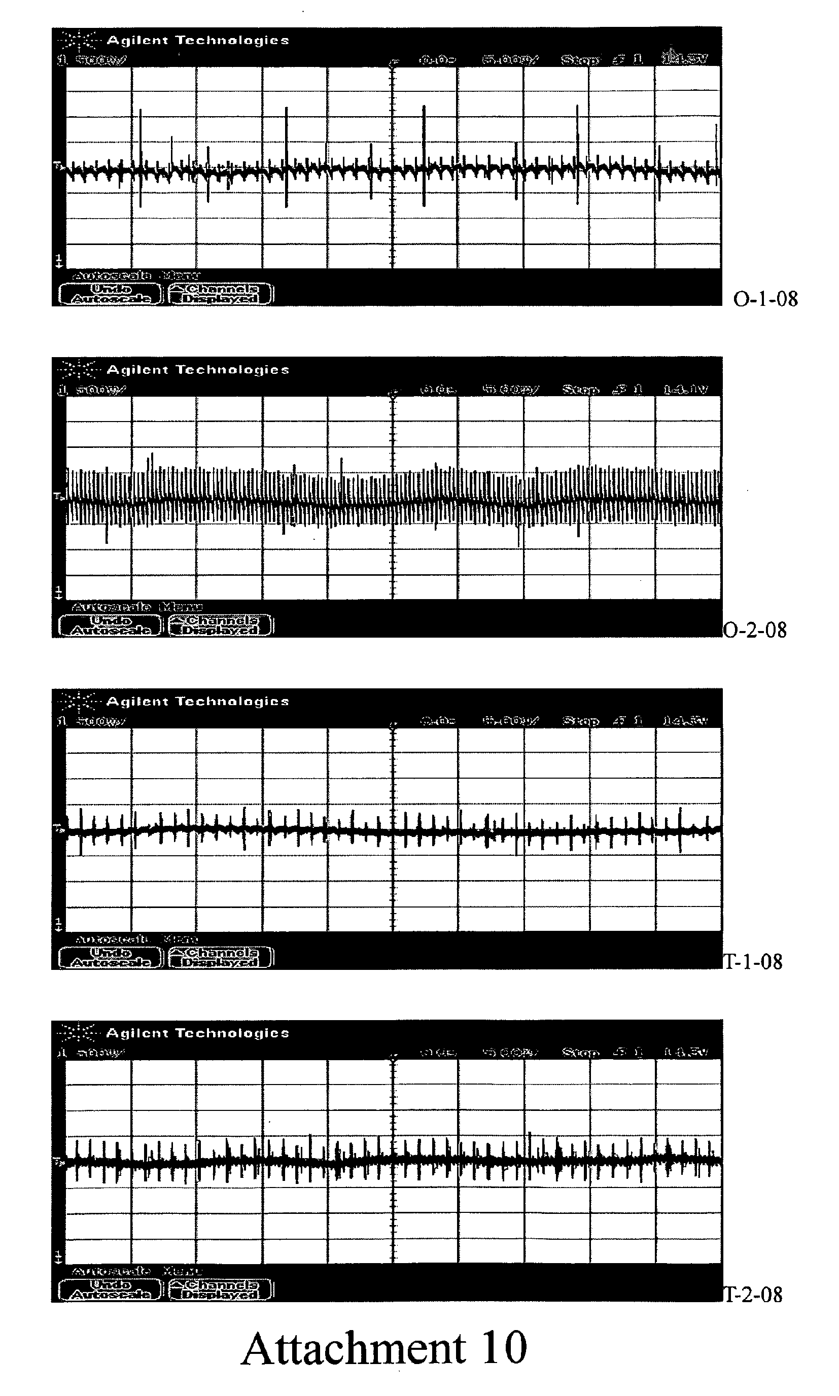
- Attachment 3 to 11 are oscilloscopic graphs of voltage wave forms taken respectively between the generator positive terminal and the negative terminals of the generator, the battery, the starting motor, the throttle valve, the gear shift controller, the compressor, the ABS, the engine cover, the chassis with/without installing the loop grounding wire when engine is making no load running at idle speed and 200rpm.
- Attachment 12 is a list enumerating the voltage wave form expressed in parameter words measured between the generator positive terminal and the negative terminals of various component devices with/without installing the loop grounding wire when vehicle engine is making full load running at idle speed and 2000rpm.
- Attachments 13 to 21 are oscilloscopic graphs of voltage wave forms taken respectively between the generator positive terminal and the negative terminals of the generator, the battery, the starting motor, the throttle valve, the gear shift controller, the compressor, the ABS, the engine cover, the chassis with/without installing the loop grounding wire when engine is making full load running at idle speed and 200rpm.
- the wiring system of the present invention is laid in the vehicle engine chamber 4 so as not to affect the structural strength of the vehicle.
- the wire interconnects the negative terminal of a generator 41, the grounding terminal of a gear shift controller 42, an engine cover 43, the negative pole of a battery unit 44, the negative terminal of a starting motor 45, the negative terminal of ABS 46, the negative terminal of a vehicle computer 47, the negative terminal of a throttle valve 48, the grounding terminal of a dash board 49, the negative terminal of a compressor 50, the negative terminal of a relay assembly 51, and the grounding terminal of a chassis 52 so as to form a closed loop grounding wire.
- the functional devices joined to this loop are a surge absorber 1 and a surge suppresser 2, and a plurality of nodes are provided on the way of the loop wire in order to connect the aforementioned terminals with the loop wire.
- the positive conductor 14 of the surge absorber 1, a first conductor 26 of the surge suppresser 2 and the connector 3 connected to the positive pole of the battery unit 44 are connected together.
- a negative conductor 15 of the surge absorber 1 is connected to the negative terminal of the generator 41, while a second conductor 27 of the surge suppresser 2 is connected to the positive terminal of the generator 41.
- the closed loop grounding system is divided by nodes en route into several wiring sections.
- the first side goes counter clockwise beginning from a first node 31 which interconnects the negative terminal of generator 41 and the grounding terminal of gear shift controller 42, a second node 32 to which a first grounding terminal 52 of the chassis is connected, a third node 33 to which the grounding terminal 43 of the engine caver is connected, and ending at a fourth node 34 to which a second grounding terminal 52 of the chassis is connected.
- the second side goes counter clockwise beginning from a fifth node 35 which interconnects the negative pole of the battery unit 44 and a third grounding terminal of the chassis, a sixth node 36 to which both the negative terminals of ABS 46 and the starting motor 45 are connected, a seventh node 37 to which the negative terminals of the vehicle computer 47 and the grounding terminal of the dash board 49 are connected, a eighth node 38 to which the grounding terminal of the throttle valve 48 and a fourth grounding terminal 52 of the chassis are connected, and ending at a ninth node 39 to which the grounding terminal of the compressor 50 and a fifth grounding terminal 52 of the chassis are connected.
- Fig. 4 and 8 show respectively the schematic and perspective views of the conductor used to construct the loop grounding system of the present invention.
- the conductor is formed of a high electric conductive core 301 sheathed with an insulation material 302.
- Fig. 1 and 6 show respectively the cross sectional and the perspective views of the surge absorber 1.
- the essential components of the surge absorber 1 are a resistor 16, a fuse element 17, an indication lamp18, and a plurality of capacitor 19 disposed on an electrical circuit board 13 which is accommodated in an inner cavity 23.
- the inner cavity 12 is enclosed by a housing 11 composed of two sub-housings.
- Two lead wires 14 and 15 are extended out of the housing 11 from same side, and are respectively connected to the positive and negative terminals of the surge absorber 1.
- the resistor 16 is used to control the voltage and current of the indication lamp 18, and the fuse element 17 is for overcurrent protection of the surge absorber 1 and other components as well.
- the indication lamp 18 indicates whether the surge absorber 1 is energized.
- the wiring diagram of the surge absorber is shown in Fig. 2.
- Fig. 3 and 7 show respectively the cross sectional and the perspective views of surge suppresser 2.
- it is essentially a hollow annular magnetic core 24 formed of several successively arrayed sub-cores in an inner cavity 22 of an environmental protective heat resistive plastic housing 21, and an insulated electric conductor 25 coiling around the annular magnetic core 24 and passing the central passage 241 formed by the hollow portion of the magnetic core 24, is extended out of the surge suppresser 2 from both sides of the housing 21 respectively with a first and a second lead wires 26 and 27.
- the inner cavity 22 in the housing 21 is filled with an insulated environmental protective material 23.
- the surge suppresser 2 serves to suppress the surge current produced by the generator 41 so as to protect the other component devices form possible damage and minimize the intensity of harmful electromagnetic wave.
Landscapes
- Engineering & Computer Science (AREA)
- Life Sciences & Earth Sciences (AREA)
- Sustainable Development (AREA)
- Sustainable Energy (AREA)
- Power Engineering (AREA)
- Transportation (AREA)
- Mechanical Engineering (AREA)
- Emergency Protection Circuit Devices (AREA)
Abstract
Description
- The present invention relates to voltage stabilizing and surge preventing vehicle loop grounding system, and more particularly, to a grounding system on which the essential components of the vehicle whose negative terminals being connected are protected from possible attack of electric surge and pulsating voltage of the generator by appropriate surge absorbing means, and the generator voltage is stabilized by effective grounding system.
- In keeping pace with the progress of automobile manufacturing technology, a lot of electronic products have been equipped in the automobile in order to improve its performance. As the electronic component is liable to yielding to the environmental conditions such as high ambient temperature and moisture resulting in varying its impedance and unabling to keep its signal level even generate multi functional signal or damage the connected electronic components.
- The steel chassis of the automobile is to be used as the passage of grounding current. However its impedance will very following the change of temperature and time of service. This might cause variation of the input signal level to the automobile computer (ECU) from the sensor. Consequently, ECU may possibly send a malfunctional or an untimely signal to the control device thereby causing improper operation of the vehicle.
- A malfunctional signal or an untimely signal may lead to incomplete conbustion of the engine owning to improper density of the vaporized fuel and produce pollutant exhausted gas. The surge current and pulsating voltage produce by the automobile generator will cause vibration and noise of D.C motors installed in the vehicle such as the fan motor and the refrigerator compressor. In the worst case, damage other electronic devices or radiate excessive electromagnetic wave.
- Conventional energy saving means provided in the vehicle utilizes several sections of a specific magnetic wire to interconnect the nodes on the negative side return conductor so as to reduce the impedance of the electrical circuit. However, the electrical circuit of a vehicle so constructed has several noteworthy shortcomings that 1. The battery units is charged by the generator when the vehicle is moving, the grounding current is supplied from the negative side of the generator and not from the negative pole of the
battery unit 2. The magnet wire used as a negative conductor may reduce the impedance of the circuit but at the same time, intensify the surge produced by the generator that greatly threats the insulation of other electronic devices provided in the vehicle such as the air flow sensor of the vehicle computer. 3. The lagging signal current carried in the magnet wire affects the coordinative action among the component devices in the vehicle electrical system, such as ignition timing, nozzle jet velocity etc., and lowers overall efficiency of the vehicle. - For these defects noticeable on the prior art, an improvement is seriously required.
- The inventor has plunged into this matter for years to studying and improving these defects and come up with this invention, which is able to eliminate the defects mentioned above.
- The main object of the present invention is to provide a vehicle loop grounding system capable of promoting vehicle efficiency and prolonging its lifetime by coordinating the action among the component devices in the vehicle electrical system by precisely adjusting the ignition time to obtain complete fuel combustion, sawing fuel consumption, increasing output power, and minimizing pollutant exhaust gas.
- Another object of the present invention is to provide a vehicle loop grounding system capable of stabilizing the generator voltage to reduce vibration and noise by forming an effective grounding system.
- Another object of the present invention is to provide a vehicle loop grounding system capable of absorbing surge wave to protect the security of various electronic component devices and avoid radiation of excessive electromagnetic waves.
- Another object of the present invention is to provide a vehicle loop grounding system capable of minimizing the impedance of the electrical circuit to assure prompt reaction of the safety bladder and intensity the brightness of the vehicle lights.
- To achieve the above objects, the vehicle loop grounding system is laid in the engine chamber, and is interconnecting the negative terminals of the generator, the gear shift controller, the engine cover, the battery unit, the starting motor, the anti stick brake motor, the vehicle computer, the throttle valve controller, the dash board, the compressor, the relay assembly, to the grounding terminal of the chassis so as to form a closed loop wire.
- The devices provided with this closed loop grounding wire include: A surge absorber having an accommodation cavity enclosed by a housing which is formed of two sections, an electrical circuit board contained inside has a positive and a negative conductor emerged out of the housing to form a circuit with a resistor, a fuse element, an indication lamp, and a plurality of capacitors. A surge suppresser having an accommodation cavity enclosed by an environment protective heat resistive plastic housing, the accommodation cavity is filled with an insulated environmental protective materials, and a plurality of successively arrayed annular magnetic hollow cores with an insulation electrical conductor wound around and passing through the channel formed by the hollow cores to extend out of the two ends of the surge suppresser thereby forming a first and a second conductors so as to be connected with the positive terminal of the surge absorber and the positive terminal of the compressor respectively.
- The loop grounding wire is provided with nine nodes which being connected to the grounding points on the engine cover and the corresponding negative terminals of the component devices with one or more than one conductor.
- The drawings disclose an illustrative embodiment of the present invention, which serves to exemplify the various advantages and objects hereof, and are as follows:
- Fig.1 is a cross sectional view of the surge absorber of the present invention ;
- Fig.2 is the wiring diagram of the surge absorber showing in Fig. 1 ;
- Fig.3 is a cross sectional view of the surge suppresser of the present invention ;
- Fig.4 is a schematic view of the grounding conductor used in the present invention ;
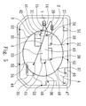
- Fig. 5 is a wiring diagram of the vehicle loop grounding system according to the present invention ;
- Fig. 6 to Fig. 8 show respectively the perspective views of the surge absorber, the surge suppresser, and the grounding conductor used in the present invention.
-
Attachment 1 is a list enumerating the grounding resistances measured between the negative terminal of the generator and the negative terminals of various component devices with/without installing the loop grounding wire when vehicle engine stands still and the battery unit is disconnected. It is clear that the grounding resistances in every part are lowered when installing the loop grounding wire of the present invention. -
Attachment 2 is a list enumerating the voltage wave form expressed in parameter words measured between the generator positive terminal and the negative terminals of various component devices with/without installing the loop grounding wire when vehicle engine is making no load running at idle speed and 2000rpm. -
Attachment 3 to 11 are oscilloscopic graphs of voltage wave forms taken respectively between the generator positive terminal and the negative terminals of the generator, the battery, the starting motor, the throttle valve, the gear shift controller, the compressor, the ABS, the engine cover, the chassis with/without installing the loop grounding wire when engine is making no load running at idle speed and 200rpm. -
Attachment 12 is a list enumerating the voltage wave form expressed in parameter words measured between the generator positive terminal and the negative terminals of various component devices with/without installing the loop grounding wire when vehicle engine is making full load running at idle speed and 2000rpm. -
Attachments 13 to 21 are oscilloscopic graphs of voltage wave forms taken respectively between the generator positive terminal and the negative terminals of the generator, the battery, the starting motor, the throttle valve, the gear shift controller, the compressor, the ABS, the engine cover, the chassis with/without installing the loop grounding wire when engine is making full load running at idle speed and 200rpm. - Referring to Fig. 5, the wiring system of the present invention is laid in the
vehicle engine chamber 4 so as not to affect the structural strength of the vehicle. The wire interconnects the negative terminal of agenerator 41, the grounding terminal of agear shift controller 42, anengine cover 43, the negative pole of abattery unit 44, the negative terminal of astarting motor 45, the negative terminal ofABS 46, the negative terminal of avehicle computer 47, the negative terminal of athrottle valve 48, the grounding terminal of adash board 49, the negative terminal of acompressor 50, the negative terminal of arelay assembly 51, and the grounding terminal of achassis 52 so as to form a closed loop grounding wire. The functional devices joined to this loop are asurge absorber 1 and asurge suppresser 2, and a plurality of nodes are provided on the way of the loop wire in order to connect the aforementioned terminals with the loop wire. Thepositive conductor 14 of the surge absorber 1, afirst conductor 26 of thesurge suppresser 2 and theconnector 3 connected to the positive pole of thebattery unit 44 are connected together. Anegative conductor 15 of thesurge absorber 1 is connected to the negative terminal of thegenerator 41, while asecond conductor 27 of thesurge suppresser 2 is connected to the positive terminal of thegenerator 41. - By so, the closed loop grounding system is divided by nodes en route into several wiring sections. The first side goes counter clockwise beginning from a
first node 31 which interconnects the negative terminal ofgenerator 41 and the grounding terminal ofgear shift controller 42, asecond node 32 to which afirst grounding terminal 52 of the chassis is connected, athird node 33 to which thegrounding terminal 43 of the engine caver is connected, and ending at afourth node 34 to which asecond grounding terminal 52 of the chassis is connected. - The second side goes counter clockwise beginning from a
fifth node 35 which interconnects the negative pole of thebattery unit 44 and a third grounding terminal of the chassis, asixth node 36 to which both the negative terminals ofABS 46 and thestarting motor 45 are connected, aseventh node 37 to which the negative terminals of thevehicle computer 47 and the grounding terminal of thedash board 49 are connected, aeighth node 38 to which the grounding terminal of thethrottle valve 48 and afourth grounding terminal 52 of the chassis are connected, and ending at aninth node 39 to which the grounding terminal of thecompressor 50 and afifth grounding terminal 52 of the chassis are connected. - Referring to Fig. 4 and 8, which show respectively the schematic and perspective views of the conductor used to construct the loop grounding system of the present invention. The conductor is formed of a high electric
conductive core 301 sheathed with aninsulation material 302. - Referring to Fig. 1 and 6, which show respectively the cross sectional and the perspective views of the surge absorber 1. The essential components of the surge absorber 1 are a
resistor 16, afuse element 17, an indication lamp18, and a plurality ofcapacitor 19 disposed on anelectrical circuit board 13 which is accommodated in aninner cavity 23. Theinner cavity 12 is enclosed by ahousing 11 composed of two sub-housings. Twolead wires housing 11 from same side, and are respectively connected to the positive and negative terminals of the surge absorber 1. Theresistor 16 is used to control the voltage and current of theindication lamp 18, and thefuse element 17 is for overcurrent protection of the surge absorber 1 and other components as well. Theindication lamp 18 indicates whether thesurge absorber 1 is energized. The wiring diagram of the surge absorber is shown in Fig. 2. - Fig. 3 and 7 show respectively the cross sectional and the perspective views of surge suppresser 2. it is essentially a hollow annular
magnetic core 24 formed of several successively arrayed sub-cores in aninner cavity 22 of an environmental protective heat resistiveplastic housing 21, and an insulatedelectric conductor 25 coiling around the annularmagnetic core 24 and passing thecentral passage 241 formed by the hollow portion of themagnetic core 24, is extended out of thesurge suppresser 2 from both sides of thehousing 21 respectively with a first and asecond lead wires inner cavity 22 in thehousing 21 is filled with an insulated environmentalprotective material 23. thesurge suppresser 2 serves to suppress the surge current produced by thegenerator 41 so as to protect the other component devices form possible damage and minimize the intensity of harmful electromagnetic wave. - For laying out the loop grounding wire shown in Fig. 5, the fallowing steps are followed:
- (A) connecting the negative terminal of the
surge absorber 1 to the negative terminal of thegenerator 41 with itsnegative conductor 15; - (B) connecting the
second conductor 27 of thesurge suppresser 2 to the positive terminal of thegenerator 41; - (C) connecting the
positive conductor 15 of thesurge absorber 1, thefirst conductor 26 of thesurge suppresser 2, and theconductor 3 from the positive pole of thebattery unit 44 together; - (D) using two
conductors 3, each from one side to connect the negative terminal of thegenerator 41 and the negative pole of thebattery unit 44, so as to form a closed loop grounding wire; - (E) connecting the negative terminal of the
gear shift controller 42 to thefirst node 31 of the loop grounding wire using at least oneconductor 3; - (F) connecting all of the nodes to the
corresponding grounding terminals 52 withconductors 3; - (G) connecting the grounding terminal of the
engine cover 43 to thethird node 33 of the loop grounding wire using at least oneconductor 3; - (H) connecting the negative terminal of
ABS 46 to thesixth node 36 of the loop grounding wire using at least oneconductor 3; - (I) connecting the negative terminal of the starting
motor 45 to thesixth node 36 of the loop grounding wire using at least oneconductor 3; - (J) connecting the negative terminal of the
vehicle computer 47 to theseventh node 37 of the loop grounding wire using at least oneconductor 3; - (K) connecting the common grounding terminal of the
dash board 49 to theseventh node 37 of the loop grounding wire using at least oneconductor 3; - (L) connecting the negative terminal of the
throttle valve 48 to theeighth node 38 of the loop grounding wire using at least oneconductor 3; - (M) connecting the negative terminal of the
compressor 50 to theninth node 39 of the loop grounding wire using at least oneconductor 3; - (N) connecting the negative terminal of the
relay assembly 51 to theninth node 39 of the loop grounding wire; and - (O) completing a multi-tapped loop grounding system.
- In all, it emerges from the above description that the voltage stabilizing and surge preventing vehicle grounding system provided by the invention has several noteworthy features which serve to palliate the shortcomings of the vehicle grounding system system provided according to the prior art, namely:
- (1) A reliable grounding contribute to lowering the grounding resistance of the mechanical components and stabilizing the output voltage of the vehicle generator that leads to helping engine have a timely ignition thereby making perfect combution of fuel, increasing engines power output, saving fuel consumption, and clearing the pollutant exhaust gas.
- (2) Alleviates, the vehicle vibration and diminishes the mechanical noise.
- (3) Installation of surge absorber and surge suppresser protects the mechanical components from being damaged by impulse voltage.
- (4) An excess radiation of the electromagnetic wave from the vehicle generator is prevented.
- (5) Other advantages such as effective function of ABS, improved vehicle illamination, enhanced response of the security bladder.
- Many changes and modifications in the above described embodiment of the invention can , of course, be carried out without departing from the scope thereof. Accordingly, to promote the progress in science and the useful arts, the invention is disclosed and is intended to be limited only by the scope of the appended claims.




Claims (11)
- Voltage stabilizing and surge preventing vehicle grounding system being laid in the engine chamber 4 interconnecting the negative terminals of the vehicle generator 41, the gear shift controller 42, the engine cover 43, the battery unit 44, the starting motor 45, the antistick brake motor(ABS) 46, the vehicle computer 47, the throttle valve 48, the dash board 49, the compressor 50, the relay assembly 51 to the grounding terminal of the chassis 52 so as to form a closed loop wire;
wherein the devices provided with this closed loop grounding wire include:a surge absorber 1 having an accommodation cavity 12 enclosed by a housing 11 formed of two sections, an electrical circuit board 13 contained inside has a positive and a negative conductor emerged out of said housing 11 to form a circuit with a resistor 16, a fuse element 17, an indication lamp 18, and a plurality of capacitors 19;a surge suppresser 2 having an accommodation cavity 22 enclosed by an environmental protective heat resistive plastic housing 21 filled with an insulated environmental protective material 23, and a plurality of successively arrayed annular magnetic hollow cores 241 with an insulation electrical conductor 25 wound around and passing through the channel formed by the hallow cores to extend out of the two ends of said surge suppresser 2 thereby forming a first and a second conductors 26, 27; anda multi-tapped closed loop grounding wires provided with nine nodes on it. - The grounding system as in claim 1, wherein the negative terminal of said surge absorber 1 is connected to the negative terminal of said vehicle generator 41 with a conductor, while the positive terminal of said vehicle generator 41 is connected to the first conductor 26 of said surge suppresser 2 and the positive pole of said battery unit 44 with a conductor, while the second conductor 27 of said surge suppresser 2 is connected to the positive terminal of said vehicle generator 41, said multi-tapped closed loop grounding wire is connected to the negative terminal of said vehicle generator 41 and the negative pole of said battery unit 44 using at least two conductors.
- The grounding system as in claim 1, wherein said closed loop grounding wire is connected to the negative terminal of said gear shift controller 42 with a conductor from its first node 31.
- The grounding system as in claim 1, wherein said closed loop grounding wire is connected to a first grounding terminal of said chassis 52 with a conductor from its second node 32.
- The grounding system as in claim 1, wherein said closed loop grounding wire is connected to said engine cover 43 with a conductor from its third node 33.
- The grounding system as in claim 1, wherein said closed loop grounding wire is connected to a second grounding terminal of said chassis 52 with a conductor from its fourth node 34.
- The grounding system as in claim 1, wherein said closed loop grounding wire is connected to a third grounding terminal of said chassis 52 with a conductor form its fifth node 34.
- The grounding system as in claim 1, wherein said closed loop grounding wire is connected to the negative terminals of said ABS 46 and said starting motor with a conductor form its sixth node 36.
- The grounding system as in claim 1, wherein said closed loop grounding wire is connected to the negative terminals of said vehicle computer 47 and said dash board 49 with two conductors form its seventh node 36.
- The grounding system as in claim 1, wherein said closed loop grounding wire is connected to the grounding terminal of said throttle valve 48 and a fourth grounding terminal of said chassis 52 with a wire from its eighth node 38.
- The grounding system as in claim 1, wherein said closed loop grounding wire is connected to the grounding terminals of said compressor 50 and said relay assembly 51, and a fifth grounding terminal 35 of said chassis 52 with a wire from its ninth node 39.
Priority Applications (3)
| Application Number | Priority Date | Filing Date | Title |
|---|---|---|---|
| AT05011150T ATE430336T1 (en) | 2005-05-23 | 2005-05-23 | AUTOMATIC GROUNDING SYSTEM WITH VOLTAGE STABILIZATION AND SURGE PROTECTION CIRCUIT |
| EP05011150A EP1727015B1 (en) | 2005-05-23 | 2005-05-23 | Voltage stabilizing and surge preventing vehicle grounding system |
| DE602005014213T DE602005014213D1 (en) | 2005-05-23 | 2005-05-23 | Automotive grounding system with voltage stabilization and overvoltage protection circuitry |
Applications Claiming Priority (1)
| Application Number | Priority Date | Filing Date | Title |
|---|---|---|---|
| EP05011150A EP1727015B1 (en) | 2005-05-23 | 2005-05-23 | Voltage stabilizing and surge preventing vehicle grounding system |
Publications (2)
| Publication Number | Publication Date |
|---|---|
| EP1727015A1 true EP1727015A1 (en) | 2006-11-29 |
| EP1727015B1 EP1727015B1 (en) | 2009-04-29 |
Family
ID=35414562
Family Applications (1)
| Application Number | Title | Priority Date | Filing Date |
|---|---|---|---|
| EP05011150A Expired - Lifetime EP1727015B1 (en) | 2005-05-23 | 2005-05-23 | Voltage stabilizing and surge preventing vehicle grounding system |
Country Status (3)
| Country | Link |
|---|---|
| EP (1) | EP1727015B1 (en) |
| AT (1) | ATE430336T1 (en) |
| DE (1) | DE602005014213D1 (en) |
Citations (7)
| Publication number | Priority date | Publication date | Assignee | Title |
|---|---|---|---|---|
| US3098966A (en) * | 1960-08-26 | 1963-07-23 | Gen Motors Corp | Protective circuit for transistor regulators |
| US4841259A (en) * | 1986-09-13 | 1989-06-20 | Ferdy Mayer | Wave propagation structures for eliminating voltage surges and absorbing transients |
| US5304849A (en) * | 1989-06-09 | 1994-04-19 | Chen Haw Renn | Method and apparatus for automobile security system |
| WO2001032479A1 (en) * | 1999-11-05 | 2001-05-10 | Cellstop International Limited | A vehicle anti-theft device |
| US6366439B1 (en) * | 1998-03-07 | 2002-04-02 | Bing Lin Yang | Surge absorber without chips |
| US6498710B1 (en) * | 1997-04-08 | 2002-12-24 | X2Y Attenuators, Llc | Paired multi-layered dielectric independent passive component architecture resulting in differential and common mode filtering with surge protection in one integrated package |
| EP1359033A1 (en) * | 2001-12-06 | 2003-11-05 | Matsushita Electric Industrial Co., Ltd. | Air conditioner |
-
2005
- 2005-05-23 DE DE602005014213T patent/DE602005014213D1/en not_active Expired - Fee Related
- 2005-05-23 EP EP05011150A patent/EP1727015B1/en not_active Expired - Lifetime
- 2005-05-23 AT AT05011150T patent/ATE430336T1/en not_active IP Right Cessation
Patent Citations (7)
| Publication number | Priority date | Publication date | Assignee | Title |
|---|---|---|---|---|
| US3098966A (en) * | 1960-08-26 | 1963-07-23 | Gen Motors Corp | Protective circuit for transistor regulators |
| US4841259A (en) * | 1986-09-13 | 1989-06-20 | Ferdy Mayer | Wave propagation structures for eliminating voltage surges and absorbing transients |
| US5304849A (en) * | 1989-06-09 | 1994-04-19 | Chen Haw Renn | Method and apparatus for automobile security system |
| US6498710B1 (en) * | 1997-04-08 | 2002-12-24 | X2Y Attenuators, Llc | Paired multi-layered dielectric independent passive component architecture resulting in differential and common mode filtering with surge protection in one integrated package |
| US6366439B1 (en) * | 1998-03-07 | 2002-04-02 | Bing Lin Yang | Surge absorber without chips |
| WO2001032479A1 (en) * | 1999-11-05 | 2001-05-10 | Cellstop International Limited | A vehicle anti-theft device |
| EP1359033A1 (en) * | 2001-12-06 | 2003-11-05 | Matsushita Electric Industrial Co., Ltd. | Air conditioner |
Also Published As
| Publication number | Publication date |
|---|---|
| ATE430336T1 (en) | 2009-05-15 |
| EP1727015B1 (en) | 2009-04-29 |
| DE602005014213D1 (en) | 2009-06-10 |
Similar Documents
| Publication | Publication Date | Title |
|---|---|---|
| JP2014111928A (en) | Knocking detection device and ignition timing control system | |
| JP3950140B2 (en) | Engine grounding system | |
| JPS6368773A (en) | Ignition coil for multicylinder internal combustion engine | |
| US7301747B2 (en) | Voltage stabilizing and surge preventing vehicle grounding system | |
| AU2005331756B2 (en) | Voltage stabilizing and surge preventing vehicle grounding system | |
| EP1727015A1 (en) | Voltage stabilizing and surge preventing vehicle grounding system | |
| Gehring et al. | Modeling of the automotive 14 V power net for voltage stability analysis | |
| US7004155B2 (en) | Ignition apparatus for internal combustion engine | |
| JP4531754B2 (en) | Split exciter system | |
| JP4058061B2 (en) | Vehicle conductor device having spike current preventing stable voltage and method for connecting the same | |
| KR20140046834A (en) | Battery sensor module for vehicle | |
| JPH08261020A (en) | Internal combustion engine with intake pipe at least partially made of plastic | |
| US6880539B2 (en) | Ignition apparatus for an internal combustion engine and a manufacturing method therefor | |
| KR200366731Y1 (en) | Equipment for noise removal of vehicles | |
| JP3137108U (en) | Gasoline engine efficiency improvement device | |
| JP2004122871A (en) | Power supply circuit for automobile | |
| TWI244446B (en) | A vehicle electrical wiring method for stabilizing voltage and preventing transient surge | |
| NL8303601A (en) | ELECTRICAL CORD. | |
| JP4126995B2 (en) | Control unit for internal combustion engine and manufacturing method thereof | |
| KR200355642Y1 (en) | Low Voltage Pin of Ignition Coil for Auto Mobile | |
| CN1076444C (en) | Anti-interference flexible igniting line with high-energy capacitor | |
| KR20060014593A (en) | Automotive Noise Reduction Device | |
| US20060288989A1 (en) | Auxiliary device for engine spark plug ignition | |
| KR20070099516A (en) | Constant voltage and surge prevention vehicle grounding device and grounding method | |
| TWM586515U (en) | Optimization device for vehicle electric signals |
Legal Events
| Date | Code | Title | Description |
|---|---|---|---|
| PUAI | Public reference made under article 153(3) epc to a published international application that has entered the european phase |
Free format text: ORIGINAL CODE: 0009012 |
|
| 17P | Request for examination filed |
Effective date: 20060828 |
|
| AK | Designated contracting states |
Kind code of ref document: A1 Designated state(s): AT BE BG CH CY CZ DE DK EE ES FI FR GB GR HU IE IS IT LI LT LU MC NL PL PT RO SE SI SK TR |
|
| AX | Request for extension of the european patent |
Extension state: AL BA HR LV MK YU |
|
| AKX | Designation fees paid |
Designated state(s): AT BE BG CH CY CZ DE DK EE ES FI FR GB GR HU IE IS IT LI LT LU MC NL PL PT RO SE SI SK TR |
|
| GRAP | Despatch of communication of intention to grant a patent |
Free format text: ORIGINAL CODE: EPIDOSNIGR1 |
|
| GRAS | Grant fee paid |
Free format text: ORIGINAL CODE: EPIDOSNIGR3 |
|
| GRAA | (expected) grant |
Free format text: ORIGINAL CODE: 0009210 |
|
| AK | Designated contracting states |
Kind code of ref document: B1 Designated state(s): AT BE BG CH CY CZ DE DK EE ES FI FR GB GR HU IE IS IT LI LT LU MC NL PL PT RO SE SI SK TR |
|
| REG | Reference to a national code |
Ref country code: GB Ref legal event code: FG4D |
|
| REG | Reference to a national code |
Ref country code: CH Ref legal event code: EP |
|
| REF | Corresponds to: |
Ref document number: 602005014213 Country of ref document: DE Date of ref document: 20090610 Kind code of ref document: P |
|
| REG | Reference to a national code |
Ref country code: IE Ref legal event code: FG4D |
|
| NLV1 | Nl: lapsed or annulled due to failure to fulfill the requirements of art. 29p and 29m of the patents act | ||
| PG25 | Lapsed in a contracting state [announced via postgrant information from national office to epo] |
Ref country code: FI Free format text: LAPSE BECAUSE OF FAILURE TO SUBMIT A TRANSLATION OF THE DESCRIPTION OR TO PAY THE FEE WITHIN THE PRESCRIBED TIME-LIMIT Effective date: 20090429 Ref country code: LT Free format text: LAPSE BECAUSE OF FAILURE TO SUBMIT A TRANSLATION OF THE DESCRIPTION OR TO PAY THE FEE WITHIN THE PRESCRIBED TIME-LIMIT Effective date: 20090429 Ref country code: PT Free format text: LAPSE BECAUSE OF FAILURE TO SUBMIT A TRANSLATION OF THE DESCRIPTION OR TO PAY THE FEE WITHIN THE PRESCRIBED TIME-LIMIT Effective date: 20090829 Ref country code: ES Free format text: LAPSE BECAUSE OF FAILURE TO SUBMIT A TRANSLATION OF THE DESCRIPTION OR TO PAY THE FEE WITHIN THE PRESCRIBED TIME-LIMIT Effective date: 20090809 Ref country code: AT Free format text: LAPSE BECAUSE OF FAILURE TO SUBMIT A TRANSLATION OF THE DESCRIPTION OR TO PAY THE FEE WITHIN THE PRESCRIBED TIME-LIMIT Effective date: 20090429 |
|
| PG25 | Lapsed in a contracting state [announced via postgrant information from national office to epo] |
Ref country code: SE Free format text: LAPSE BECAUSE OF FAILURE TO SUBMIT A TRANSLATION OF THE DESCRIPTION OR TO PAY THE FEE WITHIN THE PRESCRIBED TIME-LIMIT Effective date: 20090729 Ref country code: PL Free format text: LAPSE BECAUSE OF FAILURE TO SUBMIT A TRANSLATION OF THE DESCRIPTION OR TO PAY THE FEE WITHIN THE PRESCRIBED TIME-LIMIT Effective date: 20090429 Ref country code: IS Free format text: LAPSE BECAUSE OF FAILURE TO SUBMIT A TRANSLATION OF THE DESCRIPTION OR TO PAY THE FEE WITHIN THE PRESCRIBED TIME-LIMIT Effective date: 20090829 Ref country code: NL Free format text: LAPSE BECAUSE OF FAILURE TO SUBMIT A TRANSLATION OF THE DESCRIPTION OR TO PAY THE FEE WITHIN THE PRESCRIBED TIME-LIMIT Effective date: 20090429 Ref country code: SI Free format text: LAPSE BECAUSE OF FAILURE TO SUBMIT A TRANSLATION OF THE DESCRIPTION OR TO PAY THE FEE WITHIN THE PRESCRIBED TIME-LIMIT Effective date: 20090429 |
|
| PGFP | Annual fee paid to national office [announced via postgrant information from national office to epo] |
Ref country code: DE Payment date: 20090630 Year of fee payment: 5 |
|
| PG25 | Lapsed in a contracting state [announced via postgrant information from national office to epo] |
Ref country code: MC Free format text: LAPSE BECAUSE OF NON-PAYMENT OF DUE FEES Effective date: 20090531 |
|
| REG | Reference to a national code |
Ref country code: CH Ref legal event code: PL |
|
| PG25 | Lapsed in a contracting state [announced via postgrant information from national office to epo] |
Ref country code: RO Free format text: LAPSE BECAUSE OF FAILURE TO SUBMIT A TRANSLATION OF THE DESCRIPTION OR TO PAY THE FEE WITHIN THE PRESCRIBED TIME-LIMIT Effective date: 20090429 Ref country code: LI Free format text: LAPSE BECAUSE OF NON-PAYMENT OF DUE FEES Effective date: 20090531 Ref country code: EE Free format text: LAPSE BECAUSE OF FAILURE TO SUBMIT A TRANSLATION OF THE DESCRIPTION OR TO PAY THE FEE WITHIN THE PRESCRIBED TIME-LIMIT Effective date: 20090429 Ref country code: DK Free format text: LAPSE BECAUSE OF FAILURE TO SUBMIT A TRANSLATION OF THE DESCRIPTION OR TO PAY THE FEE WITHIN THE PRESCRIBED TIME-LIMIT Effective date: 20090429 Ref country code: CH Free format text: LAPSE BECAUSE OF NON-PAYMENT OF DUE FEES Effective date: 20090531 Ref country code: CZ Free format text: LAPSE BECAUSE OF FAILURE TO SUBMIT A TRANSLATION OF THE DESCRIPTION OR TO PAY THE FEE WITHIN THE PRESCRIBED TIME-LIMIT Effective date: 20090429 |
|
| PG25 | Lapsed in a contracting state [announced via postgrant information from national office to epo] |
Ref country code: BE Free format text: LAPSE BECAUSE OF FAILURE TO SUBMIT A TRANSLATION OF THE DESCRIPTION OR TO PAY THE FEE WITHIN THE PRESCRIBED TIME-LIMIT Effective date: 20090429 Ref country code: SK Free format text: LAPSE BECAUSE OF FAILURE TO SUBMIT A TRANSLATION OF THE DESCRIPTION OR TO PAY THE FEE WITHIN THE PRESCRIBED TIME-LIMIT Effective date: 20090429 |
|
| REG | Reference to a national code |
Ref country code: FR Ref legal event code: ST Effective date: 20100129 |
|
| PLBE | No opposition filed within time limit |
Free format text: ORIGINAL CODE: 0009261 |
|
| STAA | Information on the status of an ep patent application or granted ep patent |
Free format text: STATUS: NO OPPOSITION FILED WITHIN TIME LIMIT |
|
| REG | Reference to a national code |
Ref country code: IE Ref legal event code: MM4A |
|
| GBPC | Gb: european patent ceased through non-payment of renewal fee |
Effective date: 20090729 |
|
| PG25 | Lapsed in a contracting state [announced via postgrant information from national office to epo] |
Ref country code: BG Free format text: LAPSE BECAUSE OF FAILURE TO SUBMIT A TRANSLATION OF THE DESCRIPTION OR TO PAY THE FEE WITHIN THE PRESCRIBED TIME-LIMIT Effective date: 20090729 |
|
| 26N | No opposition filed |
Effective date: 20100201 |
|
| PG25 | Lapsed in a contracting state [announced via postgrant information from national office to epo] |
Ref country code: IE Free format text: LAPSE BECAUSE OF NON-PAYMENT OF DUE FEES Effective date: 20090523 Ref country code: FR Free format text: LAPSE BECAUSE OF NON-PAYMENT OF DUE FEES Effective date: 20090629 |
|
| PG25 | Lapsed in a contracting state [announced via postgrant information from national office to epo] |
Ref country code: GB Free format text: LAPSE BECAUSE OF NON-PAYMENT OF DUE FEES Effective date: 20090729 |
|
| PG25 | Lapsed in a contracting state [announced via postgrant information from national office to epo] |
Ref country code: GR Free format text: LAPSE BECAUSE OF FAILURE TO SUBMIT A TRANSLATION OF THE DESCRIPTION OR TO PAY THE FEE WITHIN THE PRESCRIBED TIME-LIMIT Effective date: 20090730 |
|
| PG25 | Lapsed in a contracting state [announced via postgrant information from national office to epo] |
Ref country code: IT Free format text: LAPSE BECAUSE OF FAILURE TO SUBMIT A TRANSLATION OF THE DESCRIPTION OR TO PAY THE FEE WITHIN THE PRESCRIBED TIME-LIMIT Effective date: 20090429 |
|
| PG25 | Lapsed in a contracting state [announced via postgrant information from national office to epo] |
Ref country code: LU Free format text: LAPSE BECAUSE OF NON-PAYMENT OF DUE FEES Effective date: 20090523 Ref country code: DE Free format text: LAPSE BECAUSE OF NON-PAYMENT OF DUE FEES Effective date: 20101201 |
|
| PG25 | Lapsed in a contracting state [announced via postgrant information from national office to epo] |
Ref country code: HU Free format text: LAPSE BECAUSE OF FAILURE TO SUBMIT A TRANSLATION OF THE DESCRIPTION OR TO PAY THE FEE WITHIN THE PRESCRIBED TIME-LIMIT Effective date: 20091030 |
|
| PG25 | Lapsed in a contracting state [announced via postgrant information from national office to epo] |
Ref country code: TR Free format text: LAPSE BECAUSE OF FAILURE TO SUBMIT A TRANSLATION OF THE DESCRIPTION OR TO PAY THE FEE WITHIN THE PRESCRIBED TIME-LIMIT Effective date: 20090429 |
|
| PG25 | Lapsed in a contracting state [announced via postgrant information from national office to epo] |
Ref country code: CY Free format text: LAPSE BECAUSE OF FAILURE TO SUBMIT A TRANSLATION OF THE DESCRIPTION OR TO PAY THE FEE WITHIN THE PRESCRIBED TIME-LIMIT Effective date: 20090429 |