EP1727005A1 - Screwing crown and method to assembly such a crown on a watch case - Google Patents
Screwing crown and method to assembly such a crown on a watch case Download PDFInfo
- Publication number
- EP1727005A1 EP1727005A1 EP05104391A EP05104391A EP1727005A1 EP 1727005 A1 EP1727005 A1 EP 1727005A1 EP 05104391 A EP05104391 A EP 05104391A EP 05104391 A EP05104391 A EP 05104391A EP 1727005 A1 EP1727005 A1 EP 1727005A1
- Authority
- EP
- European Patent Office
- Prior art keywords
- ring
- tube
- crown
- screw
- locking member
- Prior art date
- Legal status (The legal status is an assumption and is not a legal conclusion. Google has not performed a legal analysis and makes no representation as to the accuracy of the status listed.)
- Granted
Links
Images


Classifications
-
- G—PHYSICS
- G04—HOROLOGY
- G04B—MECHANICALLY-DRIVEN CLOCKS OR WATCHES; MECHANICAL PARTS OF CLOCKS OR WATCHES IN GENERAL; TIME PIECES USING THE POSITION OF THE SUN, MOON OR STARS
- G04B37/00—Cases
- G04B37/08—Hermetic sealing of openings, joints, passages or slits
- G04B37/10—Hermetic sealing of openings, joints, passages or slits of winding stems
- G04B37/103—Hermetic sealing of openings, joints, passages or slits of winding stems by screwing the crown onto the case
-
- G—PHYSICS
- G04—HOROLOGY
- G04D—APPARATUS OR TOOLS SPECIALLY DESIGNED FOR MAKING OR MAINTAINING CLOCKS OR WATCHES
- G04D1/00—Gripping, holding, or supporting devices
- G04D1/0007—Gripping, holding, or supporting devices for assembly entirely by hand
Landscapes
- Physics & Mathematics (AREA)
- General Physics & Mathematics (AREA)
- Adornments (AREA)
- Gasket Seals (AREA)
Abstract
Description
La présente invention se rapporte au domaine de l'horlogerie. Elle concerne, plus particulièrement, une couronne de montre du type à visser, telle qu'une couronne de remontoir. L'invention concerne également un procédé d'assemblage d'une telle couronne sur une boîte de montre, permettant d'orienter la couronne dans une position déterminée.The present invention relates to the field of watchmaking. More particularly, it relates to a screw-type watch crown, such as a winding crown. The invention also relates to a method of assembling such a crown on a watch case, for orienting the crown in a specific position.
La fabrication et le montage de couronnes à visser sur des boîtes de montre sont bien connus. Pour des raisons esthétiques, il est primordial, lorsque la face externe des couronnes porte une marque ou un logo, de pouvoir garantir que la couronne soit ramenée dans une orientation déterminée par rapport à la boîte lorsqu'elle est en position visée.The manufacture and assembly of screw-on crowns on watch cases are well known. For aesthetic reasons, it is essential, when the external face of the crowns bears a mark or a logo, to be able to guarantee that the crown is brought back in a specific orientation relative to the box when it is in the target position.
On connaît du document
La couronne comporte en outre une deuxième partie reliée à la boîte de montre. Cette deuxième partie comprend un tube intermédiaire et un écrou destiné à immobiliser le tube sur la boîte dans une position angulaire déterminée. Le tube comporte deux tronçons filetés extérieurement qui coopèrent respectivement avec l'écrou et le taraudage indexé de la couronne.The crown further includes a second portion connected to the watch case. This second part comprises an intermediate tube and a nut intended to immobilize the tube on the box in a position determined angle. The tube comprises two externally threaded sections which cooperate respectively with the nut and the indexed tapping of the ring gear.
Le tube est monté librement dans un trou traversant lisse de la boite. Ce tube est ensuite calé à l'aide d'un gabarit pour disposer l'entrée du filetage dans une position angulaire telle que, lorsque la couronne est vissée en butée sur le tube, le logo se trouve dans une position angulaire déterminée par rapport à la boîte. Une fois cette opération de calage terminée, le tube est immobilisé par l'écrou.The tube is freely mounted in a smooth through hole in the box. This tube is then wedged using a template to arrange the thread entry in an angular position such that, when the ring is screwed abutting on the tube, the logo is in a defined angular position relative to the box. Once this calibration operation is completed, the tube is immobilized by the nut.
Outre un montage complexe, un tel dispositif présente un inconvénient supplémentaire. En effet, le positionnement du tube est effectué en fonction de la couronne particulière avec laquelle il est monté, les positions relatives des deux portions filetées étant déterminées et très difficiles à changer. Mais, si la couronne se trouve endommagée par mégarde au cours du montage ou si, à l'usage, elle se trouve détériorée et qu'un changement de couronne doit être effectué, il est alors nécessaire de supprimer l'étanchéité du tube pour pouvoir le repositionner par rapport à la boîte. L'horloger qui procède à cette réparation doit à nouveau refaire l'étanchéité et la tester, ces opérations étant particulièrement fastidieuses.In addition to a complex assembly, such a device has an additional disadvantage. Indeed, the positioning of the tube is performed according to the particular crown with which it is mounted, the relative positions of the two threaded portions being determined and very difficult to change. However, if the crown is inadvertently damaged during assembly or if, in use, it is damaged and a change of crown has to be made, it is then necessary to remove the tightness of the tube to be able to reposition it in relation to the box. The watchmaker who makes this repair must again seal and test, these operations being particularly tedious.
La présente invention a pour but de proposer une couronne à visser qui peut être orientée et réorientée facilement de manière définie par rapport à la boîte, tout en garantissant une étanchéité parfaite à l'interface entre la couronne et la boîte.The present invention aims to provide a screw-in crown that can be oriented and reoriented easily in a manner defined with respect to the box, while ensuring a perfect seal at the interface between the crown and the box.
De façon plus précise, l'invention concerne une couronne à visser destinée à prendre place sur une boîte de montre à l'intérieur de laquelle prend place un mouvement de pièce d'horlogerie, comportant:
- une tête ayant une face frontale dotée d'un logo à géométrie non circulaire et une face latérale présentant une paroi intérieure munie d'un filetage, et
- un premier tube solidaire de la tête et destiné à être relié cinématiquement audit mouvement.
- a head having a front face with a non-circular geometry logo and a side face having an inner wall with a thread, and
- a first tube secured to the head and intended to be kinematically connected to said movement.
Afin de garantir une étanchéité parfaite tout en permettant d'ajuster l'orientation du logo, la couronne à visser comprend, en outre:
- un deuxième tube, dans lequel prend place ledit premier tube, formé d'une première partie destinée à être monté à demeure sur la boite de montre et d'une deuxième partie dépassant de la boite,
- une bague filetée montée libre en rotation sur ladite deuxième partie et destinée à coopérer avec le filetage de ladite paroi intérieure, et
- un organe de blocage destiné à bloquer la rotation de ladite bague par rapport audit tube.
- a second tube, in which takes place said first tube, formed of a first portion to be permanently mounted on the watch case and a second portion protruding from the box,
- a threaded ring rotatably mounted on said second portion and intended to cooperate with the threading of said inner wall, and
- a locking member for locking the rotation of said ring relative to said tube.
Selon un premier mode de réalisation, l'organe de blocage est formé d'un écrou coopérant avec la bague filetée et destiné à s'appuyer sur la boite de montre. La deuxième partie du deuxième tube comporte un épaulement contre lequel l'écrou pousse la bague.According to a first embodiment, the locking member is formed of a nut cooperating with the threaded ring and intended to rest on the watch case. The second part of the second tube has a shoulder against which the nut pushes the ring.
Un outil est proposé pour le montage d'une couronne obtenue selon ce premier mode de réalisation. Il comporte:
- un premier élément de forme globale tubulaire, se terminant par une première extrémité dont le profil est dimensionné pour s'adapter sur l'écrou et par une deuxième extrémité présentant une structure, qui permet d'agir sur sa rotation,
- un deuxième élément de forme globale tubulaire de diamètre légèrement inférieur au diamètre intérieur du premier élément, et se terminant par une première extrémité qui peut se visser sur la bague filetée, et par une deuxième extrémité présentant une structure, qui permet d'agir sur sa rotation l'élément, ladite première extrémité laissant un espace libre entre la bague et elle, et
- un troisième élément de forme globale cylindrique de diamètre légèrement inférieur au diamètre intérieur du deuxième élément, et se terminant par une première extrémité qui peut se visser sur la bague filetée dans l'espace laissé libre par ledit deuxième élément, et par une deuxième extrémité qui présente une structure qui permet d'agir sur sa rotation.
- a first element of overall tubular shape, terminating in a first end whose profile is sized to fit on the nut and in a second end having a structure, which makes it possible to act on its rotation,
- a second element of overall tubular shape of diameter slightly smaller than the inside diameter of the first element, and terminating in a first end which can be screwed onto the threaded ring, and by a second end having a structure, which makes it possible to act on its rotating the element, said first end leaving a free space between the ring and it, and
- a third element of cylindrical overall shape with a diameter slightly smaller than the inside diameter of the second element, and terminating in a first end which can be screwed onto the threaded ring in the space left free by said second element, and by a second end which has a structure that allows to act on its rotation.
Selon un deuxième mode de réalisation, la bague comporte, à sa base appuyée contre la boite, un rebord. L'organe de blocage est une plaque serrée contre la boite, munie d'une ouverture dont le diamètre est légèrement supérieur à celui de la bague filetée, de manière à laisser passer cette dernière tout en prenant appui sur le rebord.According to a second embodiment, the ring comprises, at its base supported against the box, a flange. The locking member is a plate tight against the box, provided with an opening whose diameter is slightly greater than that of the threaded ring, so as to let the latter while resting on the edge.
Selon un troisième mode de réalisation, la deuxième partie du deuxième tube comporte un épaulement, un espace étant laissé libre entre la bague filetée et l'épaulement. L'organe de blocage est formé d'une couronne dentée fixe par rapport à la boite et d'une denture dont est munie la bague filetée. La denture peut évoluer entre une première position dans laquelle elle coopère avec la couronne dentée et une deuxième position dans laquelle elle est libre relativement à cette couronne dentée.According to a third embodiment, the second part of the second tube comprises a shoulder, a space being left free between the threaded ring and the shoulder. The locking member is formed of a ring gear fixed relative to the box and a toothing which is provided with the threaded ring. The toothing may move between a first position in which it cooperates with the ring gear and a second position in which it is free relative to this ring gear.
L'invention concerne également un procédé d'orientation d'une couronne à visser telle que définie ci-dessus, comprenant les étapes suivantes:
- montage de la couronne, la bague filetée étant maintenue par l'organe de blocage,
- définition de l'orientation initiale de ladite bague filetée par rapport audit deuxième tube,
- démontage de la couronne, la bague filetée restant maintenue par l'organe de blocage,
- libération de la bague filetée de l'organe de blocage,
- orientation de la bague filetée par rapport audit deuxième tube,
- maintien de la bague filetée par l'organe de blocage dans la position obtenue lors de l'étape précédente, et
- montage de la couronne.
- mounting of the ring, the threaded ring being held by the locking member,
- defining the initial orientation of said threaded ring with respect to said second tube,
- disassembly of the ring, the threaded ring remaining held by the locking member,
- release of the threaded ring from the locking member,
- orienting the threaded ring with respect to said second tube,
- maintaining the threaded ring by the locking member in the position obtained in the previous step, and
- mounting of the crown.
D'autres détails apparaîtront plus clairement à la lecture de la description qui suit, faite en référence au dessin annexé, dans lequel:
- les figures 1 et 2 sont des vues en coupe, respectivement assemblée et éclatée, d'une couronne à visser selon l'invention,
- la figure 3 illustre un procédé d'assemblage selon l'invention, et
- les figures 4 et 5 représentent différentes variantes de l'invention.
- FIGS. 1 and 2 are sectional views, respectively assembled and exploded, of a screw-in crown according to the invention;
- FIG. 3 illustrates an assembly method according to the invention, and
- Figures 4 and 5 show different variants of the invention.
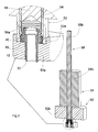
On a représenté sur les figures 1 et 2 une couronne à visser 10 montée dans une boite de montre 12 destinée à recevoir un mouvement d'horlogerie.FIGS. 1 and 2 show a screw-in
De manière classique, la couronne selon l'invention comporte une tête 14 ayant une face frontale 16 dotée d'un motif ou d'un logo. Cette marque ou ce logo présente une géométrie non circulaire. Il est donc préférable que la couronne, en position vissée, ait une orientation angulaire déterminée par rapport à la boite 12.Conventionally, the crown according to the invention comprises a
La couronne 10 est reliée cinématiquement à une tige de commande du mouvement, notamment une tige de remontoir, par l'intermédiaire d'une pièce 18 appelée piston. De manière conventionnelle, la tête 14 est reliée à ce piston 18 par des moyens de liaison comprenant un premier tube 20 rendu solidaire de la tête 14 et coulissant sur le piston 18, et un organe ressort 22 qui assure la mise en prise de la tête 14 et de la tige de commande lorsque la couronne 10 est en position dévissée.The
La tête 14 comporte également une face latérale 24 qui s'étend sur l'extrémité du tube 20, parallèlement à lui, et dont la paroi extérieure est munie de cannelures. La face latérale 24 définit, entre le tube 18 et sa paroi intérieure, un espace 26 dont le rôle apparaîtra plus loin. Cette paroi intérieure est dotée d'un filetage 28 destiné, comme on le comprendra mieux ci-après, au vissage de la couronne 10.The
Pour assembler la couronne 10 à la boite 12, un deuxième tube 30 est chassé dans un trou lisse 32traversant la carrure de la boite 12 et définissant une arête 36. De manière classique, le tube 30 peut aussi être vissé dans la boîte, le trou 32 comportant alors un taraudage. Le tube 30 est positionné à demeure, de manière parfaitement étanche, par des techniques habituelles, notamment par soudage ou par collage.To assemble the
Une partie de ce tube 30, dite externe, dépasse de la boite et comporte un premier épaulement 34 destiné à s'appuyer sur la carrure, au niveau de l'arête 36. L'extrémité de la partie externe comporte également un deuxième épaulement 38 dont le rôle apparaîtra plus loin. La partie externe est lisse et ne comporte pas de filetage.A part of this
Une bague filetée 40 est ajustée librement sur la partie externe du tube 30. Avantageusement, la bague 40 occupe toute la zone délimitée par le deuxième épaulement, c'est-à-dire la zone comprise entre les deux épaulements 34 et 38. Elle est ainsi parfaitement positionnée dans l'axe de la tige 18, entre le bord de la carrure et le deuxième épaulement 38.A threaded
Afin de garantir l'étanchéité du dispositif, des moyens d'étanchéité sont positionnés entre le premier 20 et le deuxième 30 tubes. Plus précisément, un joint 42 est logé dans une rainure 44 ménagée à l'intérieur du deuxième tube 30.In order to guarantee the tightness of the device, sealing means are positioned between the first 20 and the second 30 tubes. More specifically, a
La bague 40 étant libre en rotation sur la partie externe du tube, elle peut être orientée librement par rapport à cette dernière. Particulièrement, l'entrée de son filetage peut être positionnée avec précision. Il est ensuite nécessaire de pouvoir assurer le maintien en position de la bague 40.The
Ainsi, un organe de blocage est agencé pour positionner et maintenir la bague par rapport au tube 30. Dans le mode de réalisation des figures 1 et 2, cet organe de blocage est constitué par un écrou 46 qui se visse sur le filetage de la bague 40, du côté de la carrure. Lorsque l'écrou 46 est serré, il pousse la bague 40 contre le deuxième épaulement 38, la maintenant ainsi en position.Thus, a locking member is arranged to position and maintain the ring relative to the
Lorsque la couronne 10 a été assemblée sur la tige 18 de manière conventionnelle, le filetage 28 peut alors collaborer avec la bague filetée 40 pour visser ou dévisser la couronne 10 qui peut entraîner la tige lorsqu'elle est en position dévissée.When the
Avantageusement, le trou lisse 32 débouche, à l'extérieur de la boîte, dans un logement annulaire 48 de diamètre supérieur à celui de la couronne 10. Ainsi, le premier épaulement 36 se trouve en profondeur par rapport au bord de la carrure 12 et l'écrou 46 s'appuie sur le fond du logement 48. Ainsi, la proéminence de l'ensemble est diminuée.Advantageously, the
Dans une variante non représentée, la bague 40 comporte deux portions de filetages différents. Le filetage de la portion sur laquelle la couronne 10 est vissée présente un pas plus important que celui de la portion coopérant avec l'écrou 46. Ainsi, le dévissage de la couronne se fait facilement pour le porteur, avec une faible rotation de l'ordre de un ou deux tours, tandis que le couple de serrage de l'écrou peut être contrôlé avec précision.In a variant not shown, the
Lorsque la couronne 10 a été montée, il est nécessaire d'ajuster l'orientation du logo. Pour ce faire, un outil 50 en trois éléments 52, 54, 56 est illustré sur la figure 3, qui inclut une vue agrandie des éléments essentiels. Cet outil et son utilisation sont décrits ci-après.When the
La première étape du réglage de l'orientation du logo de la couronne consiste à définir l'orientation initiale de la bague filetée 40. La couronne 10 est montée sur la tige 18 et vissée complètement, comme le ferait l'utilisateur. L'écart angulaire du logo par rapport à la position souhaitée est alors relevé. La couronne 10 est ensuite démontée. La bague 40 étant bloquée par l'écrou 46, ces opérations se font sans qu'elle ne bouge.The first step in adjusting the orientation of the logo of the crown is to define the initial orientation of the threaded
La deuxième étape consiste à orienter la bague filetée 40 dans la position souhaitée. On comprend la difficulté de cette opération, puisque, dans un espace réduit, il faut pouvoir libérer la bague de l'organe de blocage, l'orienter avec précision et la bloquer à nouveau sans qu'elle tourne. L'outil évoqué ci-dessus a pour but de résoudre ce problème.The second step is to orient the threaded
Le premier élément 52 de l'outil est de forme globale tubulaire. Il est creux et se termine par une première extrémité 52a dont le profil est dimensionné pour s'adapter sur l'écrou. Si la carrure comporte un logement 48, cette extrémité 52a s'adapte, en outre, à la forme du logement. A sa deuxième extrémité 52b, l'élément présente une portion plus large, éventuellement moletée, qui permet de le maintenir en rotation. Le premier élément 52 est donc monté sur l'écrou.The
Le deuxième élément 54 de l'outil est également de forme tubulaire. Sur sa majeure partie, son diamètre extérieur est légèrement inférieur au diamètre intérieur du premier élément 52. Il est creux et se termine par une première extrémité 54a qui peut se visser sur la bague filetée. Cette première extrémité laisse un espace libre entre la bague et l'élément 54. A sa deuxième extrémité 54b, l'élément présente une portion plus large, éventuellement moletée, qui permet de le maintenir en rotation. Le deuxième élément est donc introduit dans le premier, et est vissé sur la bague filetée 40, jusqu'à proximité de l'écrou 46 en laissant un jeu.The
Le troisième élément 56 de l'outil est de forme globale cylindrique. Son diamètre extérieur est légèrement inférieur au diamètre intérieur du deuxième élément 54. Il se termine par une première extrémité 56a qui peut se visser sur la bague filetée 40 dans l'espace laissé libre par le deuxième élément 54. A sa deuxième extrémité 56b, l'élément présente une structure, éventuellement un moletage, qui permet son vissage sur la bague. Le troisième élément 56 est introduit dans le deuxième 54, vissé sur la bague 40 tandis que l'élément 54 est retenu en rotation, jusqu'au blocage de l'élément 56 sur l'élément 54. De la sorte, la bague filetée 40 et les deuxième 54 et troisième 56 éléments sont rendus solidaires.The
Par action sur le premier élément 52 et grâce au jeu laissé lors du montage du deuxième élément 54, l'écrou 46 est dévissé. La bague filetée 40 se trouve ainsi libérée. Il est alors facile de l'orienter en faisant pivoter de l'angle relevé lors de la première étape, l'ensemble constitué par la bague filetée 40 et les deuxième 54 et troisième 56 éléments.By action on the
L'écrou 46 est ensuite revissé et bloqué par action sur le premier élément 52. La position de la bague filetée 40 est assurée pendant cette opération en maintenant l'ensemble formé par la bague 40 et les deuxième 54 et troisième 56 éléments.The
Les éléments 54 et 56 peuvent alors être dévissés, puis le premier élément 52 est retiré. La couronne 10 est alors remontée et vissée et son orientation est contrôlée. Si nécessaire, les opérations susmentionnées sont répétées.The
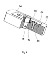
La figure 4 représente une première variante de l'organe de blocage de la bague filetée 40. Le logement 48 ménagé dans la carrure occupe une place plus importante. La bague 40 comporte, à sa base appuyée contre la carrure, un rebord 60 qui s'étend sur le fond du logement 48. Une plaque 62 dont le contour est ajusté, est disposée dans le logement 48. Elle est munie d'une ouverture dont le diamètre est légèrement supérieur à celui de la bague 40, de manière à laisser passer cette dernière tout en prenant appui sur le rebord 60. Deux vis 64 coopèrent avec deux taraudages ménagés dans la carrure afin de presser la plaquette sur le rebord 60, maintenant ainsi la bague 40 en rotation.Figure 4 shows a first variant of the locking member of the threaded
Comme ci-dessus, pour ajuster l'orientation de la bague 40, on relève son orientation initiale. Puis, après démontage de la couronne, la plaque 62 est desserrée afin d'orienter correctement la bague 40. Cette dernière est à nouveau bloquée et la couronne est remontée.As above, to adjust the orientation of the
Les vis 64 pourraient également appuyer directement sur le rebord 60 de la bague, de préférence sans le traverser, simplement en écrasant le bord du rebord 60 entre une partie de la tête de la vis et la carrure. De la sorte, il n'est pas nécessaire de retirer complètement les vis 60 pour permettre la rotation de la bague 40.The
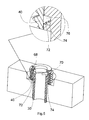
La figure 5 illustre une variante supplémentaire pour l'organe de blocage de la bague filetée 40 et comporte une vue agrandie d'une partie de cet organe. La bague filetée 40 est moins haute que dans les versions ci-dessus et n'occupe pas toute la zone comprise entre les épaulements 36 et 38. Un espace 68 est ainsi laissé libre entre la bague et le deuxième épaulement. Il est destiné à recevoir une bague fendue élastique 70, de type circlips. La bague filetée 40 comporte une denture interne 72 située à l'une de ses extrémités.Figure 5 illustrates an additional variant for the locking member of the threaded
Le tube 30 n'est pas lisse et comporte, sur son pourtour externe une couronne dentée 74 juxtaposée selon l'axe de la tige 18 à une rainure 76, située entre la couronne dentée 74 et l'espace 68. La couronne dentée 74 peut aussi être directement juxtaposé à l'espace 68, qui joue alors le rôle de la rainure 76.The
La bague filetée 40 est positionnée sur le tube 18. Lorsque les dentures de l'un et de l'autre coopèrent, la bague 40 est maintenue en rotation. Le circlips 70 est alors mis en place dans l'espace 68, s'appuyant sur le deuxième épaulement 38 pour maintenir la bague 40 dans la direction de l'axe du tube. Les dentures sont maintenues engagées et la bague est bloquée.The threaded
Pour débloquer la bague 40, il suffit de retirer le circlips 70. Elle peut alors être déplacée axialement, de manière à ce que sa denture 72 se trouve engagée dans la rainure 76 ou dans l'espace 68. La bague 40 est orientée et repositionnée pour que sa denture 72 soit à nouveau en prise avec celle 74 du tube 40. Le circlips 70 est alors remis en place pour maintenir le tout.To unlock the
Comme ci-dessus, pour ajuster l'orientation de la bague 40, on relève son orientation initiale. Puis, après démontage de la couronne, le circlips 70 est retiré afin d'orienter correctement la bague 40. Cette dernière est à nouveau bloquée en remontant le circlips 70 et la couronne est remontée.As above, to adjust the orientation of the
La portion dentée 72 dont est munie la bague filetée pourrait aussi s'étendre sur l'extérieur et coopérer avec une denture ménagée directement dans la boite 12, disposée dans le logement 48.The
Ainsi est proposé un dispositif permettant de définir avec précision l'orientation d'une couronne à visser, sans préjudice au niveau de son étanchéité avec la boîte de la montre. Le dispositif qui vient d'être décrit peut être facilement adapté à tout type de couronne à visser, notamment celle du type à vissage intérieur, l'essentiel de l'invention étant de dissocier l'organe assurant l'étanchéité du dispositif et celui assurant le vissage de la couronne.Thus is proposed a device for defining precisely the orientation of a screw-in crown, without prejudice to its sealing with the watch case. The device which has just been described can be easily adapted to any type of screw-in crown, in particular that of the internal screw-type type, the essence of the invention being to dissociate the member ensuring the tightness of the device and that ensuring screwing the crown.
Claims (12)
Priority Applications (3)
| Application Number | Priority Date | Filing Date | Title |
|---|---|---|---|
| AT05104391T ATE393416T1 (en) | 2005-05-24 | 2005-05-24 | SCREW-IN CROWN AND METHOD OF INSTALLING THIS CROWN ON A WATCH CASE |
| DE602005006249T DE602005006249D1 (en) | 2005-05-24 | 2005-05-24 | Screw-in crown and assembly process of this crown on a watch case |
| EP05104391A EP1727005B1 (en) | 2005-05-24 | 2005-05-24 | Screwing crown and method to assembly such a crown on a watch case |
Applications Claiming Priority (1)
| Application Number | Priority Date | Filing Date | Title |
|---|---|---|---|
| EP05104391A EP1727005B1 (en) | 2005-05-24 | 2005-05-24 | Screwing crown and method to assembly such a crown on a watch case |
Publications (2)
| Publication Number | Publication Date |
|---|---|
| EP1727005A1 true EP1727005A1 (en) | 2006-11-29 |
| EP1727005B1 EP1727005B1 (en) | 2008-04-23 |
Family
ID=35045397
Family Applications (1)
| Application Number | Title | Priority Date | Filing Date |
|---|---|---|---|
| EP05104391A Not-in-force EP1727005B1 (en) | 2005-05-24 | 2005-05-24 | Screwing crown and method to assembly such a crown on a watch case |
Country Status (3)
| Country | Link |
|---|---|
| EP (1) | EP1727005B1 (en) |
| AT (1) | ATE393416T1 (en) |
| DE (1) | DE602005006249D1 (en) |
Cited By (8)
| Publication number | Priority date | Publication date | Assignee | Title |
|---|---|---|---|---|
| CH699877A1 (en) * | 2008-10-31 | 2010-05-14 | Pibor Iso S A | Ring screw and method of guidance on crown as a watch box. |
| EP2385432A2 (en) | 2010-05-04 | 2011-11-09 | Rolex Sa | Watch-case |
| EP2533111A1 (en) * | 2011-06-08 | 2012-12-12 | Omega SA | Device and method for attaching a watch element with adjustable angular orientation |
| EP3279745A1 (en) * | 2016-08-02 | 2018-02-07 | Meco S.A. | Adjustable threaded crown |
| JP2019045483A (en) * | 2017-09-01 | 2019-03-22 | オメガ・エス アー | Push button device for timepiece |
| CN112433460A (en) * | 2020-11-26 | 2021-03-02 | 歌尔科技有限公司 | Crown and wrist wearing equipment with same |
| WO2021115245A1 (en) * | 2019-12-12 | 2021-06-17 | 华为技术有限公司 | Apparatus for operating wearable device |
| CN114967405A (en) * | 2022-05-30 | 2022-08-30 | 天王电子(深圳)有限公司 | Watch bottom cover assembling tool |
Citations (4)
| Publication number | Priority date | Publication date | Assignee | Title |
|---|---|---|---|---|
| CH565403B5 (en) * | 1970-09-30 | 1975-08-15 | Winding crown for water-tight watch - is capable to be screwed to element soldered to watch case | |
| FR2783939A1 (en) * | 1998-09-25 | 2000-03-31 | Herve Schick | Ten times atmospheric pressure sealed wrist watch with flush adjustment control button, can be screwed out for time adjustment |
| WO2001040881A1 (en) * | 1999-12-02 | 2001-06-07 | Ks 22 S.A. | Method for fixing a crown screwed on a watch case and watch case equipped with same |
| EP1124167A1 (en) * | 2000-02-08 | 2001-08-16 | Boninchi S.A. | Device for orientating a threaded watch crown |
-
2005
- 2005-05-24 AT AT05104391T patent/ATE393416T1/en not_active IP Right Cessation
- 2005-05-24 EP EP05104391A patent/EP1727005B1/en not_active Not-in-force
- 2005-05-24 DE DE602005006249T patent/DE602005006249D1/en active Active
Patent Citations (4)
| Publication number | Priority date | Publication date | Assignee | Title |
|---|---|---|---|---|
| CH565403B5 (en) * | 1970-09-30 | 1975-08-15 | Winding crown for water-tight watch - is capable to be screwed to element soldered to watch case | |
| FR2783939A1 (en) * | 1998-09-25 | 2000-03-31 | Herve Schick | Ten times atmospheric pressure sealed wrist watch with flush adjustment control button, can be screwed out for time adjustment |
| WO2001040881A1 (en) * | 1999-12-02 | 2001-06-07 | Ks 22 S.A. | Method for fixing a crown screwed on a watch case and watch case equipped with same |
| EP1124167A1 (en) * | 2000-02-08 | 2001-08-16 | Boninchi S.A. | Device for orientating a threaded watch crown |
Cited By (19)
| Publication number | Priority date | Publication date | Assignee | Title |
|---|---|---|---|---|
| EP2182417A3 (en) * | 2008-10-31 | 2010-09-01 | Pibor ISO S.A. | Screw crown and method for orienting such a crown on a watch case |
| CH699877A1 (en) * | 2008-10-31 | 2010-05-14 | Pibor Iso S A | Ring screw and method of guidance on crown as a watch box. |
| US8882342B2 (en) | 2010-05-04 | 2014-11-11 | Rolex S.A. | Watch case |
| EP2385432A2 (en) | 2010-05-04 | 2011-11-09 | Rolex Sa | Watch-case |
| WO2011137544A2 (en) | 2010-05-04 | 2011-11-10 | Rolex S.A. | Watch case |
| CN102971679B (en) * | 2010-05-04 | 2014-12-10 | 劳力士有限公司 | Watch case |
| CN102971679A (en) * | 2010-05-04 | 2013-03-13 | 劳力士有限公司 | Watch case |
| EP2533111A1 (en) * | 2011-06-08 | 2012-12-12 | Omega SA | Device and method for attaching a watch element with adjustable angular orientation |
| KR101411707B1 (en) * | 2011-06-08 | 2014-06-25 | 오메가쏘시에떼아노님 | Securing device and securing method for securing a watch element with adjustable angular orientation |
| CN102819214A (en) * | 2011-06-08 | 2012-12-12 | 奥米加股份有限公司 | Device and method for securing a watch element with adjustable angular orientation |
| CN102819214B (en) * | 2011-06-08 | 2014-12-31 | 奥米加股份有限公司 | Device and method for securing a watch element with adjustable angular orientation |
| US9003660B2 (en) | 2011-06-08 | 2015-04-14 | Omega Sa | Device and method for securing a watch element with adjustable angular orientation |
| EP3279745A1 (en) * | 2016-08-02 | 2018-02-07 | Meco S.A. | Adjustable threaded crown |
| US10228656B2 (en) | 2016-08-02 | 2019-03-12 | Meco S.A. | Screw-down orientable crown |
| JP2019045483A (en) * | 2017-09-01 | 2019-03-22 | オメガ・エス アー | Push button device for timepiece |
| WO2021115245A1 (en) * | 2019-12-12 | 2021-06-17 | 华为技术有限公司 | Apparatus for operating wearable device |
| CN112433460A (en) * | 2020-11-26 | 2021-03-02 | 歌尔科技有限公司 | Crown and wrist wearing equipment with same |
| CN114967405A (en) * | 2022-05-30 | 2022-08-30 | 天王电子(深圳)有限公司 | Watch bottom cover assembling tool |
| CN114967405B (en) * | 2022-05-30 | 2023-12-05 | 天王电子(深圳)有限公司 | Watch bottom cover assembling tool |
Also Published As
| Publication number | Publication date |
|---|---|
| DE602005006249D1 (en) | 2008-06-05 |
| EP1727005B1 (en) | 2008-04-23 |
| ATE393416T1 (en) | 2008-05-15 |
Similar Documents
| Publication | Publication Date | Title |
|---|---|---|
| EP1727005B1 (en) | Screwing crown and method to assembly such a crown on a watch case | |
| EP1927037B1 (en) | Device for fixing a back on a watch middle | |
| EP2657795B1 (en) | Attachment device of an interchangeable bracelet for timepieces | |
| EP2182417A2 (en) | Screw crown and method for orienting such a crown on a watch case | |
| EP1857892B1 (en) | Watch with a rotary element | |
| EP2592500A1 (en) | Watch case comprising a crown wheel with direction memory | |
| EP2567292A2 (en) | Watch case | |
| CH713532B1 (en) | Lockable crown timepiece. | |
| WO2009030984A1 (en) | Wrist watch including a reversibility device | |
| EP3451071B1 (en) | Device with push button for a timepiece | |
| EP3279745A1 (en) | Adjustable threaded crown | |
| EP1853977B1 (en) | Lockable push-piece | |
| WO2020011512A1 (en) | Watch having a rotating bezel with bezel locking system provided with an integrated helium valve | |
| EP3805873B1 (en) | Adjustable threaded crown | |
| EP1155662A1 (en) | Coping for dental prosthesis | |
| EP3650951A1 (en) | Timepiece comprising a device for locking a valve or a crown | |
| CH716825A2 (en) | Control crown for a timepiece. | |
| EP3825778A1 (en) | Control crown for a timepiece | |
| CH707158B1 (en) | Adjustable screw-in element, for example crown for timepiece. | |
| EP3492995A1 (en) | Crown system for a timepiece | |
| EP3805871B1 (en) | Adjustable threaded crown | |
| CH714112A2 (en) | Pusher device for a timepiece. | |
| CH719814A2 (en) | Crown with oriented locking and watch case comprising such a crown. | |
| CH699777B1 (en) | watch case including a screw back. | |
| EP4174583A1 (en) | Control device for a timepiece |
Legal Events
| Date | Code | Title | Description |
|---|---|---|---|
| PUAI | Public reference made under article 153(3) epc to a published international application that has entered the european phase |
Free format text: ORIGINAL CODE: 0009012 |
|
| AK | Designated contracting states |
Kind code of ref document: A1 Designated state(s): AT BE BG CH CY CZ DE DK EE ES FI FR GB GR HU IE IS IT LI LT LU MC NL PL PT RO SE SI SK TR |
|
| AX | Request for extension of the european patent |
Extension state: AL BA HR LV MK YU |
|
| 17P | Request for examination filed |
Effective date: 20070314 |
|
| AKX | Designation fees paid |
Designated state(s): AT BE BG CH CY CZ DE DK EE ES FI FR GB GR HU IE IS IT LI LT LU MC NL PL PT RO SE SI SK TR |
|
| GRAP | Despatch of communication of intention to grant a patent |
Free format text: ORIGINAL CODE: EPIDOSNIGR1 |
|
| GRAS | Grant fee paid |
Free format text: ORIGINAL CODE: EPIDOSNIGR3 |
|
| GRAA | (expected) grant |
Free format text: ORIGINAL CODE: 0009210 |
|
| AK | Designated contracting states |
Kind code of ref document: B1 Designated state(s): AT BE BG CH CY CZ DE DK EE ES FI FR GB GR HU IE IS IT LI LT LU MC NL PL PT RO SE SI SK TR |
|
| REG | Reference to a national code |
Ref country code: GB Ref legal event code: FG4D Free format text: NOT ENGLISH |
|
| REG | Reference to a national code |
Ref country code: CH Ref legal event code: EP |
|
| REF | Corresponds to: |
Ref document number: 602005006249 Country of ref document: DE Date of ref document: 20080605 Kind code of ref document: P |
|
| REG | Reference to a national code |
Ref country code: IE Ref legal event code: FG4D |
|
| REG | Reference to a national code |
Ref country code: CH Ref legal event code: NV Representative=s name: GLN S.A. |
|
| PG25 | Lapsed in a contracting state [announced via postgrant information from national office to epo] |
Ref country code: SI Free format text: LAPSE BECAUSE OF FAILURE TO SUBMIT A TRANSLATION OF THE DESCRIPTION OR TO PAY THE FEE WITHIN THE PRESCRIBED TIME-LIMIT Effective date: 20080423 |
|
| NLV1 | Nl: lapsed or annulled due to failure to fulfill the requirements of art. 29p and 29m of the patents act | ||
| PG25 | Lapsed in a contracting state [announced via postgrant information from national office to epo] |
Ref country code: NL Free format text: LAPSE BECAUSE OF FAILURE TO SUBMIT A TRANSLATION OF THE DESCRIPTION OR TO PAY THE FEE WITHIN THE PRESCRIBED TIME-LIMIT Effective date: 20080423 Ref country code: FI Free format text: LAPSE BECAUSE OF FAILURE TO SUBMIT A TRANSLATION OF THE DESCRIPTION OR TO PAY THE FEE WITHIN THE PRESCRIBED TIME-LIMIT Effective date: 20080423 Ref country code: PT Free format text: LAPSE BECAUSE OF FAILURE TO SUBMIT A TRANSLATION OF THE DESCRIPTION OR TO PAY THE FEE WITHIN THE PRESCRIBED TIME-LIMIT Effective date: 20080923 Ref country code: BG Free format text: LAPSE BECAUSE OF FAILURE TO SUBMIT A TRANSLATION OF THE DESCRIPTION OR TO PAY THE FEE WITHIN THE PRESCRIBED TIME-LIMIT Effective date: 20080723 Ref country code: ES Free format text: LAPSE BECAUSE OF FAILURE TO SUBMIT A TRANSLATION OF THE DESCRIPTION OR TO PAY THE FEE WITHIN THE PRESCRIBED TIME-LIMIT Effective date: 20080803 |
|
| PG25 | Lapsed in a contracting state [announced via postgrant information from national office to epo] |
Ref country code: AT Free format text: LAPSE BECAUSE OF FAILURE TO SUBMIT A TRANSLATION OF THE DESCRIPTION OR TO PAY THE FEE WITHIN THE PRESCRIBED TIME-LIMIT Effective date: 20080423 Ref country code: PL Free format text: LAPSE BECAUSE OF FAILURE TO SUBMIT A TRANSLATION OF THE DESCRIPTION OR TO PAY THE FEE WITHIN THE PRESCRIBED TIME-LIMIT Effective date: 20080423 |
|
| BERE | Be: lapsed |
Owner name: PIBOR ISO S.A. Effective date: 20080531 |
|
| REG | Reference to a national code |
Ref country code: IE Ref legal event code: FD4D |
|
| PG25 | Lapsed in a contracting state [announced via postgrant information from national office to epo] |
Ref country code: IS Free format text: LAPSE BECAUSE OF FAILURE TO SUBMIT A TRANSLATION OF THE DESCRIPTION OR TO PAY THE FEE WITHIN THE PRESCRIBED TIME-LIMIT Effective date: 20080823 Ref country code: MC Free format text: LAPSE BECAUSE OF NON-PAYMENT OF DUE FEES Effective date: 20080531 |
|
| PG25 | Lapsed in a contracting state [announced via postgrant information from national office to epo] |
Ref country code: IE Free format text: LAPSE BECAUSE OF FAILURE TO SUBMIT A TRANSLATION OF THE DESCRIPTION OR TO PAY THE FEE WITHIN THE PRESCRIBED TIME-LIMIT Effective date: 20080423 Ref country code: LT Free format text: LAPSE BECAUSE OF FAILURE TO SUBMIT A TRANSLATION OF THE DESCRIPTION OR TO PAY THE FEE WITHIN THE PRESCRIBED TIME-LIMIT Effective date: 20080423 Ref country code: DK Free format text: LAPSE BECAUSE OF FAILURE TO SUBMIT A TRANSLATION OF THE DESCRIPTION OR TO PAY THE FEE WITHIN THE PRESCRIBED TIME-LIMIT Effective date: 20080423 Ref country code: CZ Free format text: LAPSE BECAUSE OF FAILURE TO SUBMIT A TRANSLATION OF THE DESCRIPTION OR TO PAY THE FEE WITHIN THE PRESCRIBED TIME-LIMIT Effective date: 20080423 Ref country code: SE Free format text: LAPSE BECAUSE OF FAILURE TO SUBMIT A TRANSLATION OF THE DESCRIPTION OR TO PAY THE FEE WITHIN THE PRESCRIBED TIME-LIMIT Effective date: 20080723 Ref country code: DE Free format text: LAPSE BECAUSE OF FAILURE TO SUBMIT A TRANSLATION OF THE DESCRIPTION OR TO PAY THE FEE WITHIN THE PRESCRIBED TIME-LIMIT Effective date: 20080724 |
|
| PG25 | Lapsed in a contracting state [announced via postgrant information from national office to epo] |
Ref country code: SK Free format text: LAPSE BECAUSE OF FAILURE TO SUBMIT A TRANSLATION OF THE DESCRIPTION OR TO PAY THE FEE WITHIN THE PRESCRIBED TIME-LIMIT Effective date: 20080423 Ref country code: RO Free format text: LAPSE BECAUSE OF FAILURE TO SUBMIT A TRANSLATION OF THE DESCRIPTION OR TO PAY THE FEE WITHIN THE PRESCRIBED TIME-LIMIT Effective date: 20080423 |
|
| PLBE | No opposition filed within time limit |
Free format text: ORIGINAL CODE: 0009261 |
|
| STAA | Information on the status of an ep patent application or granted ep patent |
Free format text: STATUS: NO OPPOSITION FILED WITHIN TIME LIMIT |
|
| PG25 | Lapsed in a contracting state [announced via postgrant information from national office to epo] |
Ref country code: BE Free format text: LAPSE BECAUSE OF NON-PAYMENT OF DUE FEES Effective date: 20080531 |
|
| 26N | No opposition filed |
Effective date: 20090126 |
|
| PG25 | Lapsed in a contracting state [announced via postgrant information from national office to epo] |
Ref country code: EE Free format text: LAPSE BECAUSE OF FAILURE TO SUBMIT A TRANSLATION OF THE DESCRIPTION OR TO PAY THE FEE WITHIN THE PRESCRIBED TIME-LIMIT Effective date: 20080423 |
|
| PG25 | Lapsed in a contracting state [announced via postgrant information from national office to epo] |
Ref country code: IT Free format text: LAPSE BECAUSE OF FAILURE TO SUBMIT A TRANSLATION OF THE DESCRIPTION OR TO PAY THE FEE WITHIN THE PRESCRIBED TIME-LIMIT Effective date: 20080423 |
|
| GBPC | Gb: european patent ceased through non-payment of renewal fee |
Effective date: 20090524 |
|
| PG25 | Lapsed in a contracting state [announced via postgrant information from national office to epo] |
Ref country code: GB Free format text: LAPSE BECAUSE OF NON-PAYMENT OF DUE FEES Effective date: 20090524 |
|
| PG25 | Lapsed in a contracting state [announced via postgrant information from national office to epo] |
Ref country code: CY Free format text: LAPSE BECAUSE OF FAILURE TO SUBMIT A TRANSLATION OF THE DESCRIPTION OR TO PAY THE FEE WITHIN THE PRESCRIBED TIME-LIMIT Effective date: 20080423 Ref country code: HU Free format text: LAPSE BECAUSE OF FAILURE TO SUBMIT A TRANSLATION OF THE DESCRIPTION OR TO PAY THE FEE WITHIN THE PRESCRIBED TIME-LIMIT Effective date: 20081024 Ref country code: LU Free format text: LAPSE BECAUSE OF NON-PAYMENT OF DUE FEES Effective date: 20080524 |
|
| PG25 | Lapsed in a contracting state [announced via postgrant information from national office to epo] |
Ref country code: TR Free format text: LAPSE BECAUSE OF FAILURE TO SUBMIT A TRANSLATION OF THE DESCRIPTION OR TO PAY THE FEE WITHIN THE PRESCRIBED TIME-LIMIT Effective date: 20080423 |
|
| PG25 | Lapsed in a contracting state [announced via postgrant information from national office to epo] |
Ref country code: GR Free format text: LAPSE BECAUSE OF FAILURE TO SUBMIT A TRANSLATION OF THE DESCRIPTION OR TO PAY THE FEE WITHIN THE PRESCRIBED TIME-LIMIT Effective date: 20080724 |
|
| PGFP | Annual fee paid to national office [announced via postgrant information from national office to epo] |
Ref country code: CH Payment date: 20120525 Year of fee payment: 8 |
|
| PGFP | Annual fee paid to national office [announced via postgrant information from national office to epo] |
Ref country code: FR Payment date: 20120607 Year of fee payment: 8 |
|
| REG | Reference to a national code |
Ref country code: CH Ref legal event code: PCAR Free format text: NEW ADDRESS: AVENUE EDOUARD-DUBOIS 20, 2000 NEUCHATEL (CH) |
|
| REG | Reference to a national code |
Ref country code: CH Ref legal event code: PL |
|
| PG25 | Lapsed in a contracting state [announced via postgrant information from national office to epo] |
Ref country code: LI Free format text: LAPSE BECAUSE OF NON-PAYMENT OF DUE FEES Effective date: 20130531 Ref country code: CH Free format text: LAPSE BECAUSE OF NON-PAYMENT OF DUE FEES Effective date: 20130531 |
|
| REG | Reference to a national code |
Ref country code: FR Ref legal event code: ST Effective date: 20140131 |
|
| PG25 | Lapsed in a contracting state [announced via postgrant information from national office to epo] |
Ref country code: FR Free format text: LAPSE BECAUSE OF NON-PAYMENT OF DUE FEES Effective date: 20130531 |