EP1726819A2 - Kraftstoff-Einspritzvorrichtung, insbesondere für eine Brennkraftmaschine mit Kraftstoff-Direkteinspritzung - Google Patents
Kraftstoff-Einspritzvorrichtung, insbesondere für eine Brennkraftmaschine mit Kraftstoff-Direkteinspritzung Download PDFInfo
- Publication number
- EP1726819A2 EP1726819A2 EP06112069A EP06112069A EP1726819A2 EP 1726819 A2 EP1726819 A2 EP 1726819A2 EP 06112069 A EP06112069 A EP 06112069A EP 06112069 A EP06112069 A EP 06112069A EP 1726819 A2 EP1726819 A2 EP 1726819A2
- Authority
- EP
- European Patent Office
- Prior art keywords
- fuel injection
- injection device
- solid
- piezoelectric actuator
- joint
- Prior art date
- Legal status (The legal status is an assumption and is not a legal conclusion. Google has not performed a legal analysis and makes no representation as to the accuracy of the status listed.)
- Granted
Links
- 239000000446 fuel Substances 0.000 title claims description 42
- 238000002347 injection Methods 0.000 title claims description 29
- 239000007924 injection Substances 0.000 title claims description 29
- 238000002485 combustion reaction Methods 0.000 title claims description 8
- 239000000463 material Substances 0.000 claims 1
- 238000007789 sealing Methods 0.000 abstract description 3
- 238000005452 bending Methods 0.000 description 4
- 239000007787 solid Substances 0.000 description 3
- 238000004519 manufacturing process Methods 0.000 description 2
- 238000004026 adhesive bonding Methods 0.000 description 1
- 230000003321 amplification Effects 0.000 description 1
- 230000005540 biological transmission Effects 0.000 description 1
- 150000001875 compounds Chemical class 0.000 description 1
- 238000006073 displacement reaction Methods 0.000 description 1
- 239000012530 fluid Substances 0.000 description 1
- 239000000156 glass melt Substances 0.000 description 1
- 238000003199 nucleic acid amplification method Methods 0.000 description 1
- 230000001105 regulatory effect Effects 0.000 description 1
Images

Classifications
-
- F—MECHANICAL ENGINEERING; LIGHTING; HEATING; WEAPONS; BLASTING
- F02—COMBUSTION ENGINES; HOT-GAS OR COMBUSTION-PRODUCT ENGINE PLANTS
- F02M—SUPPLYING COMBUSTION ENGINES IN GENERAL WITH COMBUSTIBLE MIXTURES OR CONSTITUENTS THEREOF
- F02M61/00—Fuel-injectors not provided for in groups F02M39/00 - F02M57/00 or F02M67/00
- F02M61/04—Fuel-injectors not provided for in groups F02M39/00 - F02M57/00 or F02M67/00 having valves, e.g. having a plurality of valves in series
- F02M61/10—Other injectors with elongated valve bodies, i.e. of needle-valve type
- F02M61/12—Other injectors with elongated valve bodies, i.e. of needle-valve type characterised by the provision of guiding or centring means for valve bodies
-
- F—MECHANICAL ENGINEERING; LIGHTING; HEATING; WEAPONS; BLASTING
- F02—COMBUSTION ENGINES; HOT-GAS OR COMBUSTION-PRODUCT ENGINE PLANTS
- F02M—SUPPLYING COMBUSTION ENGINES IN GENERAL WITH COMBUSTIBLE MIXTURES OR CONSTITUENTS THEREOF
- F02M51/00—Fuel-injection apparatus characterised by being operated electrically
- F02M51/005—Arrangement of electrical wires and connections, e.g. wire harness, sockets, plugs; Arrangement of electronic control circuits in or on fuel injection apparatus
-
- F—MECHANICAL ENGINEERING; LIGHTING; HEATING; WEAPONS; BLASTING
- F02—COMBUSTION ENGINES; HOT-GAS OR COMBUSTION-PRODUCT ENGINE PLANTS
- F02M—SUPPLYING COMBUSTION ENGINES IN GENERAL WITH COMBUSTIBLE MIXTURES OR CONSTITUENTS THEREOF
- F02M51/00—Fuel-injection apparatus characterised by being operated electrically
- F02M51/06—Injectors peculiar thereto with means directly operating the valve needle
- F02M51/0603—Injectors peculiar thereto with means directly operating the valve needle using piezoelectric or magnetostrictive operating means
-
- F—MECHANICAL ENGINEERING; LIGHTING; HEATING; WEAPONS; BLASTING
- F02—COMBUSTION ENGINES; HOT-GAS OR COMBUSTION-PRODUCT ENGINE PLANTS
- F02M—SUPPLYING COMBUSTION ENGINES IN GENERAL WITH COMBUSTIBLE MIXTURES OR CONSTITUENTS THEREOF
- F02M61/00—Fuel-injectors not provided for in groups F02M39/00 - F02M57/00 or F02M67/00
- F02M61/16—Details not provided for in, or of interest apart from, the apparatus of groups F02M61/02 - F02M61/14
- F02M61/168—Assembling; Disassembling; Manufacturing; Adjusting
-
- H—ELECTRICITY
- H10—SEMICONDUCTOR DEVICES; ELECTRIC SOLID-STATE DEVICES NOT OTHERWISE PROVIDED FOR
- H10N—ELECTRIC SOLID-STATE DEVICES NOT OTHERWISE PROVIDED FOR
- H10N30/00—Piezoelectric or electrostrictive devices
- H10N30/80—Constructional details
- H10N30/88—Mounts; Supports; Enclosures; Casings
-
- F—MECHANICAL ENGINEERING; LIGHTING; HEATING; WEAPONS; BLASTING
- F02—COMBUSTION ENGINES; HOT-GAS OR COMBUSTION-PRODUCT ENGINE PLANTS
- F02M—SUPPLYING COMBUSTION ENGINES IN GENERAL WITH COMBUSTIBLE MIXTURES OR CONSTITUENTS THEREOF
- F02M2200/00—Details of fuel-injection apparatus, not otherwise provided for
- F02M2200/16—Sealing of fuel injection apparatus not otherwise provided for
-
- F—MECHANICAL ENGINEERING; LIGHTING; HEATING; WEAPONS; BLASTING
- F02—COMBUSTION ENGINES; HOT-GAS OR COMBUSTION-PRODUCT ENGINE PLANTS
- F02M—SUPPLYING COMBUSTION ENGINES IN GENERAL WITH COMBUSTIBLE MIXTURES OR CONSTITUENTS THEREOF
- F02M2200/00—Details of fuel-injection apparatus, not otherwise provided for
- F02M2200/26—Fuel-injection apparatus with elastically deformable elements other than coil springs
Definitions
- the invention relates to a fuel injection device, in particular for an internal combustion engine with direct fuel injection according to the preamble of claim 1.
- Such a fuel injection device is known from the market. We are connected to a fuel rail ("rail"), where the fuel is stored under high pressure. The fuel injection device injects the fuel directly into an associated combustion chamber of the internal combustion engine. As fuel comes diesel as well as gasoline in question.
- the known fuel injection device comprises a valve element, which is actuated directly or indirectly by a piezoelectric actuator.
- a hydraulic coupler is connected between the piezoactuator and the valve element, by means of which a hydraulic transmission, generally a stroke amplification, is effected.
- a piezoelectric actuator with a relatively small stroke on the actual valve element and large strokes become.
- the strokes are identical.
- a piezoelectric actuator for switching a hydraulic switching valve, which in turn influences the position of the valve element of the fuel injection device.
- the corresponding housing-side attachment of the piezoelectric actuator in the form of a ball and socket joint is realized. Such must be made comparatively accurate, among other things, to ensure a secure seal of the prevailing in the region of the piezoelectric actuator high fuel pressure.
- Object of the present invention is to develop a fuel injection device of the type mentioned so that it can be produced inexpensively, the piezoelectric actuator has a long life, and there is a reliable seal against fuel leaks.
- the fuel injection device according to the invention can be dispensed with the ball joint bearing of the piezoelectric actuator relative to the housing. This eliminates the manufacturing and the sealing problem on the one hand.
- the inventively provided solid-state hinge can be made very inexpensive and is in one piece and therefore absolutely fluid-tight. Even at low pressures, in which the piezoelectric actuator is pressed against the solid-state joint only with comparatively little force, the good seal is maintained.
- the fuel injection device according to the invention is also easier and faster manufacturable, since a total of fewer parts must be mounted.
- such a solid-state joint can build very small and also have complex geometries that increase the range of use again.
- the basis for the fuel injection device is the recognition that the compensated angular error in the piezoelectric actuator is comparatively small and is typically in the range of 0.15 to 0.17 degrees, which is a deflection of the head facing away from the bearing of the piezoelectric actuator of about 0.2 mm corresponds.
- such an angle error can be compensated for without the transverse force acting on the piezoactuator exceeding 1 Newton.
- this behavior is achieved even with relatively wide webs of typically 0.5 mm width. Even at high fluid pressures in this case, the stability of the solid state joint is maintained.
- An internal combustion engine carries in FIG. 1 the reference numeral 10 as a whole. It comprises inter alia a combustion chamber 12 into which the fuel is injected directly from a fuel injection device 14.
- the fuel injection device 14 comprises a housing 16 in which a needle-like and in its longitudinal direction movable valve member 18 is received. Through the valve element 18, fuel discharge channels 20 can be connected to or disconnected from a high pressure port 22. Via the high-pressure connection 22, the fuel injection device 14 is connected to a fuel rail 24 ("rail"), in which the fuel, for example diesel, is stored under very high pressure. For this purpose, the fuel is conveyed by a conveyor 26 from a fuel reservoir 28 into the fuel rail 24.
- a piezoelectric actuator 30 which is controlled by a control and regulating device 32 with the interposition of an output stage, not shown.
- the piezoelectric actuator 30 is coupled to the valve element 18 with the interposition of a hydraulic coupler 34. As a result, a translation of the stroke of the piezoelectric actuator 30 is achieved.
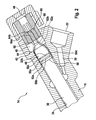
- the piezoactuator 30 is an elongated cylindrical part. It is received in an elongated recess 36 in the housing 16, which is connected via a channel 38 to the high pressure port 22. Outwardly, the recess 36 is closed by a closure element 40. By this a solid-state joint 42 is pressed against a housing-side shoulder 44.
- the solid-body joint 42 has a clamping portion 46 which has a larger diameter than a joint portion 48 of the solid-body joint 42.
- the joint portion 48 is cylindrical in the present embodiment as a whole and has approximately the same diameter as the piezoelectric actuator 30. In principle, however, a completely different cross-sectional geometry, for example, square, conceivable. Joint portion 48 and clamping portion 46 of the solid-state joint 42 are in one piece as a whole.
- the solid-state joint 42 is formed by slot-shaped recesses 50a and 50b in a first cylinder plane and slot-shaped recesses 50c and 50d in a second cylinder plane.
- the recesses 50 are introduced into the hinge portion 48 from the side so that in each case a hinge web 52a and 52b stops in the middle.
- the hinge webs 52a and 52b are about 0.5 mm thick.
- the longitudinal axes 54a and 54b of the two joint webs 52a and 52b are orthogonal to one another in the longitudinal direction of the solid-body joint 42 or the piezoelectric actuator 30, ie at right angles.
- the bending stiffness of the hinge portion 48 is selectively weakened about the axes 54a and 54b, resulting in a corresponding Biegelager. Due to the fact that a respective bending bearing is formed in the two cylinder planes and the two bending bearings have mutually orthogonal bending axes, a gimbal bearing is ultimately created which allows a deflection of the piezoactuator 30 in the two spatial directions 56a and 56b (see FIG.
- the piezoactuator 30 is glued in 58 to the hinge portion 48 of the solid state joint 42. As a result, a very rigid connection between the piezoelectric actuator 30 and the hinge portion 48 is created. Owing to Production inaccuracies may result in forced operation of the fuel injection device 14 at the opposite end of the solid-state joint 42 of the piezoelectric actuator 30. Such forced displacements may be on the order of 0.2 mm in each spatial direction 56a and 56b. Due to the gimbal bearing of the piezoelectric actuator 30 by means of the solid-state joint 42, such deflections of the piezoelectric actuator 30 can be realized without an impermissible transverse force acting on the piezoelectric actuator 30 as a result. Typically, the lateral force acting on the piezoactuator 30 remains below 1 Newton. As a result, we significantly increased the life of the piezoelectric actuator 30.
- a cylindrical depression 60 is present in the clamping section 46, on the side remote from the piezoelectric actuator 30. From this go out two inclined channels 62a and 62b, which open in the lateral surface of the hinge portion 48, in the vicinity of the clamping portion 46 (reference numeral 64 in Figure 3). Through the channels 62a and 62b, an electrical connection cable 64a and 64b is passed in each case. The channels 64a and 64b are sealed or sealed in a fluid-tight manner with a glass melt 66. The cables 64a and 64b are connected to a plug element 68 which is clamped between the closure element 40 and the solid-state joint 42.
Landscapes
- Engineering & Computer Science (AREA)
- Chemical & Material Sciences (AREA)
- Combustion & Propulsion (AREA)
- Mechanical Engineering (AREA)
- General Engineering & Computer Science (AREA)
- Manufacturing & Machinery (AREA)
- Fuel-Injection Apparatus (AREA)
Abstract
Description
- Die Erfindung betrifft eine Kraftstoff-Einspritzvorrichtung, insbesondere für eine Brennkraftmaschine mit Kraftstoff-Direkteinspritzung nach dem Oberbegriff des Anspruchs 1.
- Eine solche Kraftstoff-Einspritzvorrichtung ist vom Markt her bekannt. Sie wir an eine Kraftstoff-Sammelleitung ("Rail") angeschlossen, in der der Kraftstoff unter hohem Druck gespeichert ist. Die Kraftstoff-Einspritzvorrichtung spritzt den Kraftstoff direkt in einen ihr zugeordneten Brennraum der Brennkraftmaschine ein. Als Kraftstoff kommt Diesel ebenso wie Benzin in Frage.
- Die bekannte Kraftstoff-Einspritzvorrichtung umfasst ein Ventilelement, welches mittelbar oder unmittelbar durch einen Piezoaktor betätigt wird. Bei der mittelbaren Betätigung ist zwischen Piezoaktor und Ventilelement ein hydraulischer Koppler geschaltet, durch den eine hydraulische Übersetzung, im Allgemeinen eine Hubverstärkung, bewirkt wird. Auf diese Weise können mit einem Piezoaktor mit vergleichsweise geringem Hub am eigentlichen Ventilelement auch große Hübe realisiert werden. Bei der unmittelbaren Betätigung sind die Hübe identisch. Bekannt ist ferner die Verwendung eines Piezoaktors zum Schalten eines hydraulischen Schaltventils, welches wiederum die Stellung des Ventilelements der Kraftstoff-Einspritzvorrichtung beeinflusst.
- Um Querkräfte vom Piezoaktor im Betrieb der Kraftstoff-Einspritzvorrichtung fernzuhalten, ist die entsprechende gehäuseseitige Befestigung des Piezoaktors in Form eines Kugelgelenklagers realisiert. Ein solches muss vergleichsweise genau gefertigt sein, unter anderem auch, um eine sichere Abdichtung des im Bereich des Piezoaktors herrschenden hohen Kraftstoffdrucks zu gewährleisten.
- Aufgabe der vorliegenden Erfindung ist es, eine Kraftstoff-Einspritzvorrichtung der eingangs genannten Art so weiterzubilden, dass sie preiswert hergestellt werden kann, der Piezoaktor eine lange Lebensdauer aufweist, und eine sichere Abdichtung gegen Kraftstoffleckagen vorliegt.
- Diese Aufgabe wird durch eine Kraftstoff-Einspritzvorrichtung mit den Merkmalen des Anspruchs 1 gelöst. Vorteilhafte Ausgestaltungen sind in Unteransprüchen angegeben.
- Bei der erfindungsgemäßen Kraftstoff-Einspritzvorrichtung kann auf die Kugelgelenklagerung des Piezoaktors gegenüber dem Gehäuse verzichtet werden. Damit entfällt zum einen die Fertigungs- und zum anderen die Abdichtungsproblematik. Das erfindungsgemäß vorgesehene Festkörpergelenk kann demgegenüber sehr preiswert hergestellt werden und ist einstückig und daher absolut fluiddicht. Selbst bei niedrigen Drücken, bei denen der Piezoaktor nur mit vergleichsweise geringer Kraft gegen das Festkörpergelenk gedrückt wird, bleibt die gute Abdichtung erhalten. Die erfindungsgemäße Kraftstoff-Einspritzvorrichtung ist darüber hinaus auch einfacher und schneller fertigbar, da insgesamt weniger Teile montiert werden müssen. Schließlich kann ein solches Festkörpergelenk sehr klein bauen und auch komplexe Geometrien aufweisen, die das Einsatzspektrum nochmals erhöhen.
- Grundlage für die erfindungsgemäße Kraftstoff-Einspritzvorrichtung ist die Erkenntnis, dass der auszugleichende Winkelfehler beim Piezoaktor vergleichsweise klein ist und typischerweise im Bereich vom 0,15 bis 0,17 Grad liegt, was einer Auslenkung des vom Lager abgewandten Kopfes des Piezoaktors von ungefähr 0,2 mm entspricht. Mit einem typischen Festkörperlager kann ein solcher Winkelfehler ausgeglichen werden, ohne dass die auf den Piezoaktor wirkende Querkraft 1 Newton übersteigt. Bei einer Ausgestaltung des Festkörpergelenks mit zwei zueinander in etwa orthogonalen Gelenkstegen wird dieses Verhalten bereits bei relativ breiten Stegen von typischerweise 0,5 mm Breite erreicht. Selbst bei hohen Fluiddrücken bleibt in diesem Fall die Stabilität des Festkörpergelenks erhalten.
- Durch die Einstückigkeit des Festkörpergelenks wird auch die Durchführung eines elektrischen Anschlusskabels erleichtert, indem ein durchgehender Kanal vergleichsweise einfach eingebracht werden kann. Dies gilt ebenso für eine Verschlussmasse, mit der dieser Kanal fluiddicht vergossen wird. Aufgrund der hohen Stabilität des Festkörpergelenks kann dieses im Gehäuse auch verklemmt, verpresst oder verschweißt, oder auf eine andere Art und Weise mit hoher Kraft festgelegt werden. Auch ein Verkleben des Piezoaktors mit dem Festkörpergelenk ist aufgrund der Stabilität des Lagers einfacher.
- Nachfolgend wird ein besonders bevorzugtes Ausführungsbeispiel der vorliegenden Erfindung unter Bezugnahme auf die beiliegende Zeichnung näher erläutert. In der Zeichnung zeigen:
- Figur 1
- eine schematische Darstellung einer Brennkraftmaschine mit einer Kraftstoff-Einspritzvorrichtung;
- Figur 2
- einen teilweisen Schnitt durch einen Bereich der Kraftstoff-Einspritzvorrichtung von Figur 1;
- Figur 3
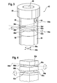
- eine perspektivische Darstellung eines Festkörpergelenks der Kraftstoff-Einspritzvorrichtung von Figur 1; und
- Figur 4
- eine schematische Darstellung zur Erläuterung der Funktion des Festkörpergelenks von Figur 3.
- Eine Brennkraftmaschine trägt in Figur 1 insgesamt das Bezugszeichen 10. Sie umfasst unter anderem einen Brennraum 12, in den der Kraftstoff direkt von einer Kraftstoff-Einspritzvorrichtung 14 eingespritzt wird.
- Die Kraftstoff-Einspritzvorrichtung 14 umfasst ein Gehäuse 16, in dem ein nadelartiges und in seiner Längsrichtung bewegliches Ventilelement 18 aufgenommen ist. Durch das Ventilelement 18 können Kraftstoff-Austrittskanäle 20 mit einem Hochdruckanschluss 22 verbunden oder von diesem getrennt werden. Über den Hochdruckanschluss 22 ist die Kraftstoff-Einspritzvorrichtung 14 an eine Kraftstoff-Sammelleitung 24 ("Rail") angeschlossen, in der der Kraftstoff, beispielsweise Diesel, unter sehr hohem Druck gespeichert ist. Hierzu wird der Kraftstoff von einer Fördereinrichtung 26 aus einem Kraftstoff-Vorratsbehälter 28 in die Kraftstoff-Sammelleitung 24 gefördert.
- Zur Betätigung des Ventilelements 18 dient bei der Kraftstoff-Einspritzvorrichtung 14 ein Piezoaktor 30, der von einer Steuer- und Regeleinrichtung 32 unter Zwischenschaltung einer nicht dargestellten Endstufe angesteuert wird. Im vorliegenden Ausführungsbeispiel ist der Piezoaktor 30 mit dem Ventilelement 18 unter Zwischenschaltung eines hydraulischen Kopplers 34 gekoppelt. Hierdurch wird eine Übersetzung des Hubs des Piezoaktors 30 erreicht.
- Wie aus Figur 2 hervorgeht, handelt es sich bei dem Piezoaktor 30 um ein langgestrecktes zylindrisches Teil. Er ist in einer länglichen Ausnehmung 36 im Gehäuse 16 aufgenommen, die über einen Kanal 38 mit dem Hochdruckanschluss 22 verbunden ist. Nach außen hin ist die Ausnehmung 36 durch ein Verschlusselement 40 verschlossen. Durch dieses wird ein Festkörpergelenk 42 gegen einen gehäuseseitigen Absatz 44 gedrückt. Hierzu verfügt das Festkörpergelenk 42 über einen Klemmabschnitt 46, der einen größeren Durchmesser aufweist als ein Gelenkabschnitt 48 des Festkörpergelenks 42. Der Gelenkabschnitt 48 ist bei dem vorliegenden Ausführungsbeispiel insgesamt zylindrisch und hat in etwa den gleichen Durchmesser wie der Piezoaktor 30. Grundsätzlich ist aber auch eine ganz andere Querschnittsgeometrie, beispielsweise quadratisch, denkbar. Gelenkabschnitt 48 und Klemmabschnitt 46 des Festkörpergelenks 42 sind insgesamt einstückig.
- Wie auch aus Figur 3 hervorgeht, wird das Festkörpergelenk 42 durch schlitzförmige Ausnehmungen 50a und 50b in einer ersten Zylinderebene und schlitzförmige Ausnehmungen 50c und 50d in einer zweiten Zylinderebene gebildet. Die Ausnehmungen 50 sind so in den Gelenkabschnitt 48 von der Seite her eingebracht, dass in der Mitte jeweils ein Gelenksteg 52a und 52b stehen bleibt. In einem typischen Ausführungsbeispiel sind die Gelenkstege 52a und 52b ungefähr 0,5 mm dick.
- Wie auch aus der schematisierten Funktionsdarstellung von Figur 4 hervorgeht, sind die Längsachsen 54a und 54b der beiden Gelenkstege 52a und 52b in Längsrichtung des Festkörpergelenks 42 bzw. des Piezoaktors 30 gesehen zueinander orthogonal, also rechtwinklig. Durch die Ausnehmungen 50a bis 50d wird die Biegesteifigkeit des Gelenkabschnitts 48 um die Achsen 54a und 54b gezielt geschwächt, wodurch sich ein entsprechendes Biegelager ergibt. Dadurch, dass in den beiden Zylinderebenen jeweils ein Biegelager gebildet ist und die beiden Biegelager zueinander orthogonale Biegeachsen aufweisen, wird letztlich eine kardanische Lagerung geschaffen, die eine Auslenkung des Piezoaktors 30 in den beiden Raumrichtungen 56a und 56b (vgl. Figur 3) erlaubt.
- Der Piezoaktor 30 ist in 58 mit dem Gelenkabschnitt 48 des Festkörpergelenks 42 verklebt. Hierdurch wird eine sehr starre Verbindung zwischen dem Piezoaktor 30 und dem Gelenkabschnitt 48 geschaffen. Aufgrund von Fertigungsungenauigkeiten können sich im Betrieb der Kraftstoff-Einspritzvorrichtung 14 Zwangsauslenkungen an dem vom Festkörpergelenk 42 entgegengesetzten Ende des Piezoaktors 30 ergeben. Derartige Zwangsauslenkungen können in der Größenordnung von 0,2 mm in jeder Raumrichtung 56a und 56b liegen. Durch die kardanische Lagerung des Piezoaktors 30 mittels des Festkörpergelenks 42 können derartige Auslenkungen des Piezoaktors 30 realisiert werden, ohne dass hierdurch eine unzulässige Querkraft auf den Piezoaktor 30 einwirkt. Typischerweise bleibt die Querkraft, die auf den Piezoaktor 30 einwirkt, unterhalb von 1 Newton. Hierdurch wir die Lebensdauer des Piezoaktors 30 deutlich erhöht.
- In dem Festkörpergelenk 42 ist im Klemmabschnitt 46, auf der vom Piezoaktor 30 abgewandten Seite, eine zylindrische Einsenkung 60 vorhanden. Von dieser gehen zwei schräge Kanäle 62a und 62b aus, die in der Mantelfläche des Gelenkabschnitts 48, in der Nähe zum Klemmabschnitt 46, münden (Bezugszeichen 64 in Figur 3). Durch die Kanäle 62a und 62b ist jeweils ein elektrisches Anschlusskabel 64a und 64b hindurchgeführt. Die Kanäle 64a und 64b sind mit einer Glaseinschmelzung 66 fluiddicht verschlossen bzw. vergossen. Die Kabel 64a und 64b sind an ein Steckerelement 68 angeschlossen, welches zwischen dem Verschlusselement 40 und dem Festkörpergelenk 42 verklemmt ist.
Claims (6)
- Kraftstoff-Einspritzvorrichtung (14), insbesondere für eine Brennkraftmaschine (10) mit Kraftstoff-Direkteinspritzung, mit einem Gehäuse (16) und einem Piezoaktor (30) zur Betätigung eines Ventilelements (18), wobei der Piezoaktor (30) an dem Gehäuse (16) gelagert ist, dadurch gekennzeichnet, dass die Lagerung ein Festkörpergelenk (42) umfasst.
- Kraftstoff-Einspritzvorrichtung (14) nach Anspruch 1, dadurch gekennzeichnet, dass das Festkörpergelenk (42) einen Gelenkabschnitt (48) umfasst, der in mindestens zwei Ebenen derart geschlitzt (50) ist, dass mindestens zwei zueinander wenigstens in etwa orthogonale Gelenkstege (52) gebildet werden.
- Kraftstoff-Einspritzvorrichtung (14) nach einem der Ansprüche 1 oder 2, dadurch gekennzeichnet, dass das Festkörpergelenk (42) mindestens einen Kanal (62) umfasst, durch den ein elektrisches Anschlusskabel (64) für den Piezoaktor (30) hindurchgeführt ist.
- Kraftstoff-Einspritzvorrichtung (14) nach Anspruch 3, dadurch gekennzeichnet, dass der Kanal (62) durch eine Verschlussmasse (66) wenigstens bereichsweise ausgefüllt, insbesondere vergossen ist.
- Kraftstoff-Einspritzvorrichtung (14) nach einem der vorhergehenden Ansprüche, dadurch gekennzeichnet, dass der Piezoaktor (30) mit dem Festkörpergelenk (42) verklebt ist (58).
- Kraftstoff-Einspritzvorrichtung (14) nach einem der vorhergehenden Ansprüche, dadurch gekennzeichnet, dass das Festkörpergelenk (42) im Gehäuse (16) verklemmt, verpresst, oder verschweißt ist.
Applications Claiming Priority (1)
| Application Number | Priority Date | Filing Date | Title |
|---|---|---|---|
| DE102005024049A DE102005024049A1 (de) | 2005-05-25 | 2005-05-25 | Kraftstoff-Einspritzvorrichtung, insbesondere für eine Brennkraftmaschine mit Kraftstoff-Direkteinspritzung |
Publications (3)
| Publication Number | Publication Date |
|---|---|
| EP1726819A2 true EP1726819A2 (de) | 2006-11-29 |
| EP1726819A3 EP1726819A3 (de) | 2009-04-29 |
| EP1726819B1 EP1726819B1 (de) | 2016-05-11 |
Family
ID=36928249
Family Applications (1)
| Application Number | Title | Priority Date | Filing Date |
|---|---|---|---|
| EP06112069.7A Expired - Lifetime EP1726819B1 (de) | 2005-05-25 | 2006-03-31 | Kraftstoff-Einspritzvorrichtung, insbesondere für eine Brennkraftmaschine mit Kraftstoff-Direkteinspritzung |
Country Status (3)
| Country | Link |
|---|---|
| EP (1) | EP1726819B1 (de) |
| JP (1) | JP2006329200A (de) |
| DE (1) | DE102005024049A1 (de) |
Families Citing this family (1)
| Publication number | Priority date | Publication date | Assignee | Title |
|---|---|---|---|---|
| JP4849096B2 (ja) | 2008-06-06 | 2011-12-28 | 株式会社デンソー | 燃料噴射弁 |
Citations (1)
| Publication number | Priority date | Publication date | Assignee | Title |
|---|---|---|---|---|
| DE19727992A1 (de) | 1997-07-01 | 1999-01-07 | Siemens Ag | Ausgleichselement zur Kompensation temperaturbedingter Längenänderung eines Objektes |
Family Cites Families (8)
| Publication number | Priority date | Publication date | Assignee | Title |
|---|---|---|---|---|
| DE19650900A1 (de) * | 1996-12-07 | 1998-06-10 | Bosch Gmbh Robert | Piezoelektrischer Aktuator |
| GB9925753D0 (en) * | 1999-10-29 | 1999-12-29 | Lucas Industries Ltd | Fuel injector |
| JP4356268B2 (ja) * | 2000-06-26 | 2009-11-04 | 株式会社デンソー | 燃料噴射装置 |
| US6548444B2 (en) * | 2001-06-20 | 2003-04-15 | Eastman Chemical Company | Tin promoted iridium catalyst for carbonylation of lower alkyl alcohols |
| DE10140529A1 (de) * | 2001-08-17 | 2003-03-06 | Bosch Gmbh Robert | Piezoelektrisches Aktormodul |
| DE10310788A1 (de) * | 2003-03-12 | 2004-09-23 | Robert Bosch Gmbh | Brennstoffeinspritzventil und Verfahren zu dessen Montage |
| EP1664525B1 (de) * | 2003-09-12 | 2008-04-23 | Siemens Aktiengesellschaft | Dosiervorrichtung |
| DE102004021920A1 (de) * | 2004-05-04 | 2005-12-01 | Robert Bosch Gmbh | Brennstoffeinspritzventil |
-
2005
- 2005-05-25 DE DE102005024049A patent/DE102005024049A1/de not_active Withdrawn
-
2006
- 2006-03-31 EP EP06112069.7A patent/EP1726819B1/de not_active Expired - Lifetime
- 2006-05-25 JP JP2006145769A patent/JP2006329200A/ja active Pending
Patent Citations (1)
| Publication number | Priority date | Publication date | Assignee | Title |
|---|---|---|---|---|
| DE19727992A1 (de) | 1997-07-01 | 1999-01-07 | Siemens Ag | Ausgleichselement zur Kompensation temperaturbedingter Längenänderung eines Objektes |
Also Published As
| Publication number | Publication date |
|---|---|
| DE102005024049A1 (de) | 2006-11-30 |
| EP1726819B1 (de) | 2016-05-11 |
| EP1726819A3 (de) | 2009-04-29 |
| JP2006329200A (ja) | 2006-12-07 |
Similar Documents
| Publication | Publication Date | Title |
|---|---|---|
| EP1307651B1 (de) | Dosierventil mit einem hydraulischen übertragungselement | |
| EP1989436B1 (de) | Kraftstoffeinspritzvorrichtung für eine brennkraftmaschine | |
| WO1998040623A1 (de) | Ventil zum steuern von flüssigkeiten | |
| DE102005059437A1 (de) | Kraftstoffinjektor | |
| EP2206912B1 (de) | Kraftstoff-Injektor | |
| EP1114273A1 (de) | Anschlussstutzen und gehäuse, insbesondere kraftstoffhochdruckspeicher, mit vorgespannt angeschweisstem anschlussstutzen für ein kraftstoffeinspritzsystem für brennkraftmaschinen | |
| WO1998057059A1 (de) | Einspritzventil | |
| EP1711707B1 (de) | Kraftstoffinjektor mit direkt angesteuertem einspritzventilglied | |
| DE102008035087B4 (de) | Einspritzventil | |
| WO2007113038A1 (de) | Kraftstoffeinspritzeinrichtung für eine mehrzylindrige brennkraftmaschine | |
| EP1726819B1 (de) | Kraftstoff-Einspritzvorrichtung, insbesondere für eine Brennkraftmaschine mit Kraftstoff-Direkteinspritzung | |
| EP2249024B1 (de) | Kraftstoffinjektor | |
| EP1576279B1 (de) | Brennstoffeinspritzventil | |
| EP2898212B1 (de) | Brennstoffeinspritzventil | |
| DE102021202729A1 (de) | Kraftstoffeinspritzeinrichtung | |
| EP0920583A1 (de) | Ventil zum steuern von flüssigkeiten | |
| WO2005080786A1 (de) | Kontaktierung der ventilnadel eines injektors für verbrennungsmotoren | |
| EP1673532B1 (de) | Hochdruckzulauf für einen common rail injektor | |
| EP1820960B1 (de) | Brennstoffeinspritzventil | |
| EP1843038B1 (de) | Kraftstoffinjektor mit einer kegeligen Gehäusehochdruckdichtung | |
| DE102005024721B4 (de) | Common-Rail-Injektor | |
| WO2007098986A1 (de) | Brennstoffeinspritzventil | |
| EP1142040A1 (de) | Aktor zum auslenken eines stellglieds und kraftstoffeinspritzventil mit einem solchen aktor | |
| DE10259730A1 (de) | Brennstoffeinspritzventil | |
| DE102006027484A1 (de) | Kraftstoffinjektor mit kraftausgeglichenem Steuerventil |
Legal Events
| Date | Code | Title | Description |
|---|---|---|---|
| PUAI | Public reference made under article 153(3) epc to a published international application that has entered the european phase |
Free format text: ORIGINAL CODE: 0009012 |
|
| AK | Designated contracting states |
Kind code of ref document: A2 Designated state(s): AT BE BG CH CY CZ DE DK EE ES FI FR GB GR HU IE IS IT LI LT LU LV MC NL PL PT RO SE SI SK TR |
|
| AX | Request for extension of the european patent |
Extension state: AL BA HR MK YU |
|
| PUAL | Search report despatched |
Free format text: ORIGINAL CODE: 0009013 |
|
| AK | Designated contracting states |
Kind code of ref document: A3 Designated state(s): AT BE BG CH CY CZ DE DK EE ES FI FR GB GR HU IE IS IT LI LT LU LV MC NL PL PT RO SE SI SK TR |
|
| AX | Request for extension of the european patent |
Extension state: AL BA HR MK YU |
|
| 17P | Request for examination filed |
Effective date: 20091029 |
|
| AKX | Designation fees paid |
Designated state(s): AT BE BG CH CY CZ DE DK EE ES FI FR GB GR HU IE IS IT LI LT LU LV MC NL PL PT RO SE SI SK TR |
|
| 17Q | First examination report despatched |
Effective date: 20110407 |
|
| GRAP | Despatch of communication of intention to grant a patent |
Free format text: ORIGINAL CODE: EPIDOSNIGR1 |
|
| INTG | Intention to grant announced |
Effective date: 20160104 |
|
| GRAS | Grant fee paid |
Free format text: ORIGINAL CODE: EPIDOSNIGR3 |
|
| GRAA | (expected) grant |
Free format text: ORIGINAL CODE: 0009210 |
|
| AK | Designated contracting states |
Kind code of ref document: B1 Designated state(s): AT BE BG CH CY CZ DE DK EE ES FI FR GB GR HU IE IS IT LI LT LU LV MC NL PL PT RO SE SI SK TR |
|
| REG | Reference to a national code |
Ref country code: GB Ref legal event code: FG4D Free format text: NOT ENGLISH |
|
| REG | Reference to a national code |
Ref country code: CH Ref legal event code: EP |
|
| REG | Reference to a national code |
Ref country code: AT Ref legal event code: REF Ref document number: 798879 Country of ref document: AT Kind code of ref document: T Effective date: 20160515 |
|
| REG | Reference to a national code |
Ref country code: IE Ref legal event code: FG4D Free format text: LANGUAGE OF EP DOCUMENT: GERMAN |
|
| REG | Reference to a national code |
Ref country code: DE Ref legal event code: R096 Ref document number: 502006014940 Country of ref document: DE |
|
| REG | Reference to a national code |
Ref country code: LT Ref legal event code: MG4D |
|
| REG | Reference to a national code |
Ref country code: NL Ref legal event code: MP Effective date: 20160511 |
|
| PG25 | Lapsed in a contracting state [announced via postgrant information from national office to epo] |
Ref country code: NL Free format text: LAPSE BECAUSE OF FAILURE TO SUBMIT A TRANSLATION OF THE DESCRIPTION OR TO PAY THE FEE WITHIN THE PRESCRIBED TIME-LIMIT Effective date: 20160511 Ref country code: FI Free format text: LAPSE BECAUSE OF FAILURE TO SUBMIT A TRANSLATION OF THE DESCRIPTION OR TO PAY THE FEE WITHIN THE PRESCRIBED TIME-LIMIT Effective date: 20160511 Ref country code: LT Free format text: LAPSE BECAUSE OF FAILURE TO SUBMIT A TRANSLATION OF THE DESCRIPTION OR TO PAY THE FEE WITHIN THE PRESCRIBED TIME-LIMIT Effective date: 20160511 |
|
| PG25 | Lapsed in a contracting state [announced via postgrant information from national office to epo] |
Ref country code: ES Free format text: LAPSE BECAUSE OF FAILURE TO SUBMIT A TRANSLATION OF THE DESCRIPTION OR TO PAY THE FEE WITHIN THE PRESCRIBED TIME-LIMIT Effective date: 20160511 Ref country code: PT Free format text: LAPSE BECAUSE OF FAILURE TO SUBMIT A TRANSLATION OF THE DESCRIPTION OR TO PAY THE FEE WITHIN THE PRESCRIBED TIME-LIMIT Effective date: 20160912 Ref country code: LV Free format text: LAPSE BECAUSE OF FAILURE TO SUBMIT A TRANSLATION OF THE DESCRIPTION OR TO PAY THE FEE WITHIN THE PRESCRIBED TIME-LIMIT Effective date: 20160511 Ref country code: GR Free format text: LAPSE BECAUSE OF FAILURE TO SUBMIT A TRANSLATION OF THE DESCRIPTION OR TO PAY THE FEE WITHIN THE PRESCRIBED TIME-LIMIT Effective date: 20160812 Ref country code: SE Free format text: LAPSE BECAUSE OF FAILURE TO SUBMIT A TRANSLATION OF THE DESCRIPTION OR TO PAY THE FEE WITHIN THE PRESCRIBED TIME-LIMIT Effective date: 20160511 |
|
| PG25 | Lapsed in a contracting state [announced via postgrant information from national office to epo] |
Ref country code: IT Free format text: LAPSE BECAUSE OF FAILURE TO SUBMIT A TRANSLATION OF THE DESCRIPTION OR TO PAY THE FEE WITHIN THE PRESCRIBED TIME-LIMIT Effective date: 20160511 |
|
| PG25 | Lapsed in a contracting state [announced via postgrant information from national office to epo] |
Ref country code: DK Free format text: LAPSE BECAUSE OF FAILURE TO SUBMIT A TRANSLATION OF THE DESCRIPTION OR TO PAY THE FEE WITHIN THE PRESCRIBED TIME-LIMIT Effective date: 20160511 Ref country code: CZ Free format text: LAPSE BECAUSE OF FAILURE TO SUBMIT A TRANSLATION OF THE DESCRIPTION OR TO PAY THE FEE WITHIN THE PRESCRIBED TIME-LIMIT Effective date: 20160511 Ref country code: RO Free format text: LAPSE BECAUSE OF FAILURE TO SUBMIT A TRANSLATION OF THE DESCRIPTION OR TO PAY THE FEE WITHIN THE PRESCRIBED TIME-LIMIT Effective date: 20160511 Ref country code: SK Free format text: LAPSE BECAUSE OF FAILURE TO SUBMIT A TRANSLATION OF THE DESCRIPTION OR TO PAY THE FEE WITHIN THE PRESCRIBED TIME-LIMIT Effective date: 20160511 Ref country code: EE Free format text: LAPSE BECAUSE OF FAILURE TO SUBMIT A TRANSLATION OF THE DESCRIPTION OR TO PAY THE FEE WITHIN THE PRESCRIBED TIME-LIMIT Effective date: 20160511 |
|
| REG | Reference to a national code |
Ref country code: DE Ref legal event code: R097 Ref document number: 502006014940 Country of ref document: DE |
|
| PG25 | Lapsed in a contracting state [announced via postgrant information from national office to epo] |
Ref country code: PL Free format text: LAPSE BECAUSE OF FAILURE TO SUBMIT A TRANSLATION OF THE DESCRIPTION OR TO PAY THE FEE WITHIN THE PRESCRIBED TIME-LIMIT Effective date: 20160511 |
|
| PLBE | No opposition filed within time limit |
Free format text: ORIGINAL CODE: 0009261 |
|
| STAA | Information on the status of an ep patent application or granted ep patent |
Free format text: STATUS: NO OPPOSITION FILED WITHIN TIME LIMIT |
|
| 26N | No opposition filed |
Effective date: 20170214 |
|
| PG25 | Lapsed in a contracting state [announced via postgrant information from national office to epo] |
Ref country code: SI Free format text: LAPSE BECAUSE OF FAILURE TO SUBMIT A TRANSLATION OF THE DESCRIPTION OR TO PAY THE FEE WITHIN THE PRESCRIBED TIME-LIMIT Effective date: 20160511 |
|
| REG | Reference to a national code |
Ref country code: CH Ref legal event code: PL |
|
| GBPC | Gb: european patent ceased through non-payment of renewal fee |
Effective date: 20170331 |
|
| PG25 | Lapsed in a contracting state [announced via postgrant information from national office to epo] |
Ref country code: MC Free format text: LAPSE BECAUSE OF FAILURE TO SUBMIT A TRANSLATION OF THE DESCRIPTION OR TO PAY THE FEE WITHIN THE PRESCRIBED TIME-LIMIT Effective date: 20160511 |
|
| REG | Reference to a national code |
Ref country code: IE Ref legal event code: MM4A |
|
| REG | Reference to a national code |
Ref country code: FR Ref legal event code: ST Effective date: 20171130 |
|
| PG25 | Lapsed in a contracting state [announced via postgrant information from national office to epo] |
Ref country code: LU Free format text: LAPSE BECAUSE OF NON-PAYMENT OF DUE FEES Effective date: 20170331 Ref country code: FR Free format text: LAPSE BECAUSE OF NON-PAYMENT OF DUE FEES Effective date: 20170331 |
|
| PG25 | Lapsed in a contracting state [announced via postgrant information from national office to epo] |
Ref country code: GB Free format text: LAPSE BECAUSE OF NON-PAYMENT OF DUE FEES Effective date: 20170331 Ref country code: LI Free format text: LAPSE BECAUSE OF NON-PAYMENT OF DUE FEES Effective date: 20170331 Ref country code: CH Free format text: LAPSE BECAUSE OF NON-PAYMENT OF DUE FEES Effective date: 20170331 Ref country code: IE Free format text: LAPSE BECAUSE OF NON-PAYMENT OF DUE FEES Effective date: 20170331 |
|
| REG | Reference to a national code |
Ref country code: BE Ref legal event code: MM Effective date: 20170331 |
|
| REG | Reference to a national code |
Ref country code: AT Ref legal event code: MM01 Ref document number: 798879 Country of ref document: AT Kind code of ref document: T Effective date: 20170331 |
|
| PG25 | Lapsed in a contracting state [announced via postgrant information from national office to epo] |
Ref country code: BE Free format text: LAPSE BECAUSE OF NON-PAYMENT OF DUE FEES Effective date: 20170331 |
|
| PGFP | Annual fee paid to national office [announced via postgrant information from national office to epo] |
Ref country code: DE Payment date: 20180517 Year of fee payment: 13 |
|
| PG25 | Lapsed in a contracting state [announced via postgrant information from national office to epo] |
Ref country code: AT Free format text: LAPSE BECAUSE OF NON-PAYMENT OF DUE FEES Effective date: 20170331 |
|
| PG25 | Lapsed in a contracting state [announced via postgrant information from national office to epo] |
Ref country code: HU Free format text: LAPSE BECAUSE OF FAILURE TO SUBMIT A TRANSLATION OF THE DESCRIPTION OR TO PAY THE FEE WITHIN THE PRESCRIBED TIME-LIMIT; INVALID AB INITIO Effective date: 20060331 |
|
| PG25 | Lapsed in a contracting state [announced via postgrant information from national office to epo] |
Ref country code: BG Free format text: LAPSE BECAUSE OF FAILURE TO SUBMIT A TRANSLATION OF THE DESCRIPTION OR TO PAY THE FEE WITHIN THE PRESCRIBED TIME-LIMIT Effective date: 20160511 |
|
| REG | Reference to a national code |
Ref country code: DE Ref legal event code: R119 Ref document number: 502006014940 Country of ref document: DE |
|
| PG25 | Lapsed in a contracting state [announced via postgrant information from national office to epo] |
Ref country code: CY Free format text: LAPSE BECAUSE OF NON-PAYMENT OF DUE FEES Effective date: 20160511 |
|
| PG25 | Lapsed in a contracting state [announced via postgrant information from national office to epo] |
Ref country code: DE Free format text: LAPSE BECAUSE OF NON-PAYMENT OF DUE FEES Effective date: 20191001 |
|
| PG25 | Lapsed in a contracting state [announced via postgrant information from national office to epo] |
Ref country code: TR Free format text: LAPSE BECAUSE OF FAILURE TO SUBMIT A TRANSLATION OF THE DESCRIPTION OR TO PAY THE FEE WITHIN THE PRESCRIBED TIME-LIMIT Effective date: 20160511 |
|
| PG25 | Lapsed in a contracting state [announced via postgrant information from national office to epo] |
Ref country code: IS Free format text: LAPSE BECAUSE OF FAILURE TO SUBMIT A TRANSLATION OF THE DESCRIPTION OR TO PAY THE FEE WITHIN THE PRESCRIBED TIME-LIMIT Effective date: 20160911 |