EP1726769A1 - Schutztür mit Türzarge - Google Patents
Schutztür mit Türzarge Download PDFInfo
- Publication number
- EP1726769A1 EP1726769A1 EP05011072A EP05011072A EP1726769A1 EP 1726769 A1 EP1726769 A1 EP 1726769A1 EP 05011072 A EP05011072 A EP 05011072A EP 05011072 A EP05011072 A EP 05011072A EP 1726769 A1 EP1726769 A1 EP 1726769A1
- Authority
- EP
- European Patent Office
- Prior art keywords
- door
- locking
- locking member
- door frame
- arrangement according
- Prior art date
- Legal status (The legal status is an assumption and is not a legal conclusion. Google has not performed a legal analysis and makes no representation as to the accuracy of the status listed.)
- Granted
Links
Images



Classifications
-
- E—FIXED CONSTRUCTIONS
- E05—LOCKS; KEYS; WINDOW OR DOOR FITTINGS; SAFES
- E05B—LOCKS; ACCESSORIES THEREFOR; HANDCUFFS
- E05B65/00—Locks or fastenings for special use
- E05B65/10—Locks or fastenings for special use for panic or emergency doors
- E05B65/104—Locks or fastenings for special use for panic or emergency doors actuated in response to heat, e.g. with fusible element, bimetal, memory shape or swelling material
-
- E—FIXED CONSTRUCTIONS
- E06—DOORS, WINDOWS, SHUTTERS, OR ROLLER BLINDS IN GENERAL; LADDERS
- E06B—FIXED OR MOVABLE CLOSURES FOR OPENINGS IN BUILDINGS, VEHICLES, FENCES OR LIKE ENCLOSURES IN GENERAL, e.g. DOORS, WINDOWS, BLINDS, GATES
- E06B5/00—Doors, windows, or like closures for special purposes; Border constructions therefor
- E06B5/10—Doors, windows, or like closures for special purposes; Border constructions therefor for protection against air-raid or other war-like action; for other protective purposes
- E06B5/16—Fireproof doors or similar closures; Adaptations of fixed constructions therefor
- E06B5/164—Sealing arrangements between the door or window and its frame, e.g. intumescent seals specially adapted therefor
-
- E—FIXED CONSTRUCTIONS
- E06—DOORS, WINDOWS, SHUTTERS, OR ROLLER BLINDS IN GENERAL; LADDERS
- E06B—FIXED OR MOVABLE CLOSURES FOR OPENINGS IN BUILDINGS, VEHICLES, FENCES OR LIKE ENCLOSURES IN GENERAL, e.g. DOORS, WINDOWS, BLINDS, GATES
- E06B5/00—Doors, windows, or like closures for special purposes; Border constructions therefor
- E06B5/10—Doors, windows, or like closures for special purposes; Border constructions therefor for protection against air-raid or other war-like action; for other protective purposes
- E06B5/16—Fireproof doors or similar closures; Adaptations of fixed constructions therefor
- E06B5/167—Devices blocking doors or windows inside its frame in case of fire
Definitions
- the present invention relates to an arrangement comprising a protective door and an associated door frame, a protective door for such an arrangement, a door frame for such an arrangement, a locking unit for such an arrangement and a kit for converting a protective door with associated door frame to such an arrangement according to the Preambles of the independent claims.
- Protective doors are generally used where interconnected building areas in the event of a fire must be fireproof separable from each other, for example, to prevent the ingress of smoke into other parts of the building and / or expansion of the fire.
- Such protective doors and the associated door frames are in most cases made of metal profiles, with the result that these bend in an arc-shaped manner with a strong one-sided heating, as they typically occur in the event of fire.
- this can possibly lead to inadmissibly large gaps between the door and the door frame, even if the door catch is latched, so that the protective function of the safety doors is severely impaired.
- a first aspect of the invention relates to an arrangement comprising a protective door with an associated door frame.
- a locking member On the protective door or on the door frame, a locking member is arranged, which in a strong heating of the environment of the protective door, e.g. As a result of a fire in their vicinity, creates a positive connection in the door opening direction between the closed protective door and the door frame.
- the locking member is actuated by means of a thermal expansion of solid and / or liquid substances generated by this heating, e.g. by a bimetal element, by a Dehnstoff emotions or hydraulically by expansion of a liquid, so that there is a forced coupling of heating and actuation of the locking member.
- the arrangement according to the invention makes it possible to provide door systems which are reliable, cost-effective and low-maintenance and, in the event of fire, prevent the protective door and door frame from divergence - also referred to as the door leaf offset - at least in the area of the locking element or at an admissible or desired level limit.
- the locking member is bimetallbetätigt, which has the advantage that in a simple manner relatively large actuation paths are possible.
- the locking member is a movably mounted on the protective door or on the door frame component, which in case of fire by means of a separately formed on the Principle of thermal expansion based, preferably bimetallic actuator due to heating of the same from a rest position in which it does not hinder opening and closing of the protective door, in a locking position in which it prevents opening of the protective door by the positive locking or limited to a structurally provided Schoerielsatzsatzmass, is moved.
- a separately formed on the Principle of thermal expansion based, preferably bimetallic actuator due to heating of the same from a rest position in which it does not hinder opening and closing of the protective door, in a locking position in which it prevents opening of the protective door by the positive locking or limited to a structurally provided Schoerielsatzsatzmass, is moved.
- the locking member is designed as a slide, preferably as a locking bolt, which is axially displaced by the actuator in case of fire.
- Such locking members require only low actuation forces and at the same time endure relatively high stresses.
- the locking member is disposed on an outer surface of the protective door or door frame, e.g. outside on the upper frame profile, in such a way that it is displaced or pivoted at a heating of the actuator in case of fire substantially perpendicular to the door opening direction and thereby forms a projection which can produce the desired positive locking in the door opening direction with a corresponding stop body.
- the actuator is arranged on the outer surface of the protective door or door frame, so that it can heat up as quickly as possible in case of fire.
- the locking member and the actuator are formed together as an independent locking unit, which, preferably with its own housing, for example by means of screws or rivets, is mounted on the outer surface of the door or door frame. This has the advantage that it can be dispensed with special stop plates and an arrangement of the locking unit at a location on the Protective door or the door frame is possible, which in the case of fire very early undergoes a strong warming, so that can be realized very short reaction times.
- the locking member is located on an end face of the protective door, that is to say on a surface forming the door circumference, or on an inner surface of the door frame which, when the protective door is closed, faces an end face of the protective door. It is arranged such that it is pushed out or pivoted outwardly from this end face or inner surface in case of fire substantially perpendicular to the door opening direction upon heating of its actuating member.
- a lock in the region of the opposing profile contours of the protective door and door frame is possible, which on the outside of the protective door or on the door frame mounted components, which may be optically disturbing, can be dispensed with.
- the preferably bimetallic actuator outside on the end face of the protective door or on the door opening defining the inner surface of the door frame is arranged, for. when the door is closed directly opposite a face of the same, as this can achieve good reaction times and the actuator is not visible when the protective door is closed.
- the actuator is designed as a bimetallic tab, which is connected at one of its two ends, optionally via other components, fixed to the protective door or the door frame, for example by means of a fastening screw or a pop rivet.
- the other end is coupled to the locking member, so that the entire temperature-induced change in shape of the bimetallic element for the movement of the locking member relative to the protective door or the door frame is usable and correspondingly large movement paths are possible.
- the locking member is designed as a locking bolt with a discontinuously reduced in a range cross section, preferably with a circumferential groove
- the bimetallic flap has an end, preferably extending in the longitudinal direction, preferably outwardly open slot in which the is arranged in reduced cross-sectional area of the locking bolt.
- the locking member is arranged such that it causes a positive connection between the protective door and door frame in the area of TÜberberkante, preferably in the door hinges facing away from half of the upper edge of the door or in the upper region of the door leading edge in case of fire, since the heat-related Deformation of the door in this area is typically the largest.
- a kurdehnungsbetätigter preferably bimetallic locking member is additionally arranged in the threshold area in the half facing the door hinges or in the lower region of the door leading edge, which causes a positive connection between the protective door and door frame in case of warming in case of fire in this area, in order to prevent that displaced by the arranged in the upper region locking member obstructed door leaf offset in the lower area and there leads to an unacceptably large gap between the protective door and door frame.
- the additional locking member is preferably identically formed and operated as the arranged in the upper region locking member.
- the protective door is preferably a metallic fire door or smoke protection door, preferably with a frame construction of metal profiles.
- the door frame which is also preferably formed of metal profiles, on a solid support structure, such. a wall of masonry or concrete, connected so that their temperature-induced bending is severely hampered in case of fire, the benefits of the invention are particularly evident.
- the locking member and the body in the door opening direction in the event of fire with this one form fit, e.g. a stopper plate, designed and arranged such that results in a striking of the locking member in the door opening direction of the aforementioned corporeality a certain door leaf offset in the door opening direction.
- the possible door leaf offset measured in the region of the locking member, is at most 20 mm. This results in the advantage that a certain reaction time for the thermal expansion-actuated locking remains, whereby the reliability significantly increased and a displacement of the door leaf offset in the threshold area, which could lead to impermissibly large gaps between the protective door and door frame in this area, as far as possible avoided.
- a second aspect of the invention relates to a safety door having at least one thermal expansion actuated, preferably bimetallic locking member as set forth above in the first aspect of the invention, which when heated in a direction substantially perpendicular to the door opening direction, to enable a door-locking positive locking of the safety door in one this surrounding door frame in case of fire.
- a protective door can be formed by adding a door frame with a suitable abutment body for the locking member, in a simple and cost-effective manner inventive arrangements according to the first aspect of the invention.
- a third aspect of the invention relates to a door frame with at least one heat expansion actuated, preferably bimetallic locking member as set forth above in the first aspect of the invention, which emerges when heated in a direction substantially perpendicular to the door opening direction, to enable a positive locking in the door opening direction in the door frame arranged protective door in case of fire.
- a door frame can be, by adding a protective door with a suitable Anschlagismezier for the locking member, in a simple and cost-effective manner according to the invention form arrangements according to the first aspect of the invention.
- a fourth aspect of the invention relates to a locking unit for an inventive arrangement according to the first aspect of the invention, which comprises a locking member and a thermal expansion actuated, preferably bimetallic actuator disposed on a common carrier.
- the locking member and the actuating member are coupled to each other in such a way that heating of the actuating member leads to a displacement or pivoting movement of the locking member relative to the carrier.
- the locking member and the actuating member are arranged in a common, separately formed by the guard door and the door frame, such that a corporeality of the locking member with increasing heating of the actuating member progressively over the outer contour of the housing.
- locking units can be in a simple manner from conventional safety door and door frame arrangements according to the invention form by the locking unit is attached outside such on the guard or on the door frame, that in case of fire, a door offset by striking the locking member on the door frame (at the protective door attached to the locking unit) or by abutment of the locking member on the protective door (with locking unit attached to the door frame) is prevented or limited to a permissible or intended measure.
- attaching the locking unit to a protective door or a door frame also results in an inventive protective door according to the second aspect of the invention or a novel door frame according to the third aspect of the invention.
- a fifth aspect of the invention relates to a retrofit kit for the retrofitting of a conventional protective door arrangement to an arrangement according to the first aspect of the invention.
- the kit comprises a locking bolt and a bimetallic tab, which can be coupled in such a form-fitting manner that the locking bolt can be moved forward and backward by temperature-induced change in shape of the bimetal lug.
- the kit additionally comprises a screw-in or press-in guide element for the locking bolt, e.g. a threaded rivet, which can be used in a metal profile surface and after upsetting, and optionally after an additional drilling to the desired diameter, can serve as a guide for the locking bolt.
- a screw-in or press-in guide element for the locking bolt e.g. a threaded rivet, which can be used in a metal profile surface and after upsetting, and optionally after an additional drilling to the desired diameter, can serve as a guide for the locking bolt.
- conventional protective door arrangements can be converted in a simple and cost-effective manner to arrangements according to the invention according to the first aspect of the invention, wherein the protective door to a protective door according to the invention according to the second Aspect of the invention is converted or the door frame to a novel door frame according to the third aspect of the invention.
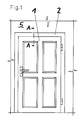
- FIG. 1 shows a front view of the arrangement
- the arrangement comprises a fire door 1, which is made as a frame construction of metal profiles, and an associated door frame 2, also made of metal profiles, which is firmly connected to a building wall 5 made of concrete.
- a fire door 1 in the region of its upper face or top edge a blazedehnungsbetuschippos locking member 3, 4, which consists of a locking bolt 3 as the actual Locking member 3 and a bimetallic tab 4 as an actuator 4 for the locking bolt 3 consists.
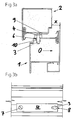
- Fig. 2b shows a plan view of that portion of the upper end face in which the locking bolt 3 and the bimetallic tab 4 are arranged, the locking bolt 3 in a perpendicular to the end face of the fire door 1 and perpendicular to the door opening direction O extending guide bore 6 mounted longitudinally displaceable.
- the bimetallic tab 4 is screwed at one of its two ends with a screw 7 flat on the top of the frame profile formed upper end surface of the fire door 1 and positively coupled at its other end in both longitudinal displacement directions of the locking bolt 3 with this, which takes place in the present case in that the locking bolt 3 has a diameter that is reduced in diameter by a circumferential groove, which is arranged in a slot 8 open in the end in the bimetal lug 4.
- the locking bolt 3 is in the locked position and thus causes a positive connection in the door opening direction O between the protective door 1 and the door frame 2 by abutting the door 9 in the door opening direction O. He is held axially by the bimetallic flap 4 bent upward due to strong heating in this position and radially guided within the guide bore 6.
- the locking bolt 3 and the stopper plate 9 are arranged to each other such that a door wing offset X of about 15 mm, measured in the region of the locking bolt 3, is possible.
- FIGS. 3 a and 3 b show views like FIGS. 2 a and 2 b of a second arrangement according to the invention, which differs from the previously shown arrangement only in that here frame profiles are used which only in the region in which the locking bolt 3 is arranged have a single thin sheet metal layer. Since a bore in this sheet metal material would not be sufficient to guide the locking bolt 3, here comes as a guide element 10 for the locking bolt 3, a guide sleeve 10 is used, which was produced by pressing and then drilling a threaded rivet.
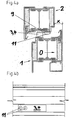
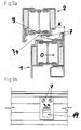
- Figures 4a and 4b, 5a and 5b and 6a and 6b respectively show views as the figures 2a and 2b of further inventive arrangements, which are common to all that both the locking member 3 and the actuator 4 are formed by a single physicality, namely from a bimetallic strip 3, 4. Such arrangements have very few moving components and are therefore particularly reliable.
- FIG. 4a The arrangement shown in Figures 4a and 4b has a similar structure as the arrangements shown in Figures 2a, 2b and 3a, 3b, but with the aforementioned essential difference that here no separate locking member (locking bolt) is present, but itself the riveted by means of two rivets 11 on the upper end face of the door 1 bimetallic strip 3, 4 bends so much upward in strong warming that it causes a positive connection in the door opening direction O with the stop plate 9 and so the possible door leaf offset X on the constructive measure provided limited. This situation is shown in Fig. 4a.
- Figures 5a and 5b show an arrangement similar to the arrangement shown in Figures 4a and 4b, which, however, differs from the latter in that the bimetallic strip 3, 4 is not transverse to the door opening direction O but along this on the upper end face of the
- the stop plate 9 is formed in this embodiment as an angle plate 9 and the bimetallic strip 3, 4 provided with an opening 14, such that in a heating-related Sichnachobenbiegen the bimetallic strip 3, 4, the free leg of the angled stopper plate 9 enters the opening 14 and thereby the positive connection in the door opening direction O results.
- Figures 6a and 6b show an arrangement similar to the arrangement shown in Figures 5a and 5b, which, however, differs from the latter in that the bimetallic strip 3, 4 has no opening and not on the band side of the upper end surface of the protective door first is fixed, but on the opposite band side of the upper end face, so that it bends upwards on strong side on the hinge side, where it then forms a positive fit in the door opening direction O with a profile nose 12 of the upper frame profile of the door frame 2. This situation is shown in Fig. 6a.
- Fig. 7 shows a view like Fig. 2a by another inventive arrangement, which differs fundamentally from the previously shown in that here a locking unit 13 according to the invention is arranged by means of several screws 7 on the gegenband statisticen outer surface of the protective door 1, which thereby the locking function perceives that emerges from her with strong warming a locking bolt 3, which then forms a positive connection in the door opening direction O with the outer surface of the upper frame profile of the door frame 2.
- the locking bolt 3 is mounted in a guide sleeve 10 in the housing 15 and is how already described in the arrangements according to Figures 2a, 2b and 3a, 3b, actuated by a bimetallic flap 4, which here, however, at its operating end has a laterally open slot for coupling with the locking bolt 3.
- the other end of the bimetallic tab 4 is fixedly connected to the housing 15.
- the invention is not limited to the use of bimetallic actuated locking members, but includes all actuation mechanisms based on thermal expansion of materials due to severe heating of the environment of the protective door.
- the locking members 3 are on the protective door 1, as shown in the figures, but on the door frame 2 so that they form a positive locking in the door opening direction O with the protective door 1 or a stop element arranged on the latter when heated cause.
Landscapes
- Engineering & Computer Science (AREA)
- Civil Engineering (AREA)
- Structural Engineering (AREA)
- Business, Economics & Management (AREA)
- Emergency Management (AREA)
- Special Wing (AREA)
Abstract
Description
- Die vorliegende Erfindung betrifft eine Anordnung umfassend eine Schutztür und eine zugehörige Türzarge, eine Schutztür für eine solche Anordnung, eine Türzarge für eine solche Anordnung, eine Verriegelungseinheit für eine solche Anordnung sowie ein Kit zum Umrüsten einer Schutztür mit zugehöriger Türzarge zu einer solchen Anordnung gemäss den Oberbegriffen der unabhängigen Ansprüche.
- Schutztüren kommen im allgemeinen dort zum Einsatz, wo miteinander verbundene Gebäudebereiche für den Fall eines Brandes brandschutzmässig voneinander trennbar sein müssen, z.B. um ein Eindringen von Rauch in weitere Gebäudeteile und/oder eine Ausdehnung des Feuers zu verhindern. Solche Schutztüren und die zugehörigen Türzargen bestehen in den meisten Fällen aus Metallprofilen, was dazu führt, dass sich diese bei einer starken einseitigen Erwärmung, wie sie.im Brandfall in der Regel auftritt, bogenförmig verbiegen. Bei zur Kaltseite hin öffnenden Türen mit fest an einer Gebäudewand angeschlossenen Türzargen kann dies bei sehr hohen Türen möglicherweise dazu führen, dass trotz eingerasteter Türfalle unzulässig grosse Spalte zwischen Tür und Türzarge entstehen, so dass die Schutzfunktion der Schutztüren stark beeinträchtigt wird. Um dies zu verhindern, werden bei derartigen Türen heute Mehrfach-Verriegelungen eingesetzt, welche jedoch insbesondere bei elektrisch entriegelbaren Türen, wie z.B. Zutrittskontrollen, zu erheblichen Mehrkosten und zu einer erhöhten Störanfälligkeit führen und zudem gegenüber Systemen mit einer einzigen Türfalle erhöhte Schliessgeräusche verursachen. Zudem sind die bekannten Systeme ungeeignet für Anwendungsbereiche, bei denen die Tür im Normalbetrieb nicht durch eine Türfalle zugehalten wird, wie z.B. bei Pendeltüren.
- Es stellt sich daher die Aufgabe, eine Anordnung mit einer Schutztür und einer zugehörigen Türzarge zur Verfügung zu stellen, welche die Nachteile des Standes der Technik nicht aufweist oder diese zumindest teilweise vermeidet.
- Diese Aufgabe wird von der Anordnung, der Schutztür, der Türzarge, der Verriegelungseinheit sowie dem Kit gemäss den unabhängigen Ansprüchen gelöst.
- Ein erster Aspekt der Erfindung betrifft eine Anordnung umfassend eine Schutztür mit einer dazugehörigen Türzarge. An der Schutztür oder an der Türzarge ist ein Verriegelungsorgan angeordnet, welches bei einer starken Erwärmung der Umgebung der Schutztür, z.B. infolge eines Feuers in deren Nähe, einen Formschluss in Türöffnungsrichtung zwischen der geschlossenen Schutztür und der Türzarge herstellt. Dabei wird das Verriegelungsorgan mittels einer durch diese Erwärmung erzeugten Wärmedehnung fester und/oder flüssiger Stoffe betätigt, z.B. durch ein Bimetall-Element, durch einen Dehnstoffkörper oder auf hydraulischem Wege durch Ausdehnung einer Flüssigkeit, so dass sich eine Zwangskopplung von Erwärmung und Betätigung des Verriegelungsorgans ergibt.
- Durch die erfindungsgemässe Anordnung wird es möglich, Türsysteme zur Verfügung zu stellen, welche zuverlässig, kostengünstig und wartungsarm sind und im Brandfall ein Auseinanderklaffen von Schutztür und Türzarge - auch als Türflügelversatz bezeichnet - zumindest im Bereich des Verriegelungsorgans verhindern oder auf ein zulässiges bzw. gewolltes Mass begrenzen.
- In einer bevorzugten Ausführungsform der Anordnung ist das Verriegelungsorgan bimetallbetätigt, was den Vorteil hat, dass auf einfache Weise relativ grosse Betätigungswege möglich sind.
- In einer weiteren bevorzugten Ausführungsform ist das Verriegelungsorgan ein an der Schutztür oder an der Türzarge beweglich gelagertes Bauteil, welches im Brandfall mittels eines separat ausgebildeten, auf dem Prinzip der Wärmedehnung basierenden, bevorzugterweise bimetallischen Betätigungsorgans infolge Erwärmung desselben von einer Ruheposition, in welcher es ein Öffnen und Schliessen der Schutztür nicht behindert, in eine Verriegelungsposition, in welcher es durch den Formschluss ein Öffnen der Schutztür verhindert oder auf ein konstruktiv vorgesehenes Türflügelversatzmass begrenzt, bewegt wird. Auf diese Weise wird es möglich, die Verriegelungsfunktion von der Betätigungsfunktion zu trennen, so dass die die jeweilige Funktion wahrnehmenden Bauteile optimal ausgelegt werden können.
- Bevorzugterweise wird dabei das Verriegelungsorgan als Schieber, bevorzugterweise als Riegelbolzen ausgebildet, welcher im Brandfall durch das Betätigungsorgan axial verschoben wird. Solche Verriegelungsorgane benötigen nur geringe Betätigungskräfte und ertragen gleichzeitig relativ grosse Beanspruchungen.
- Mit Vorteil wird das Verriegelungsorgan an einer Aussenfläche der Schutztür oder der Türzarge angeordnet, z.B. aussen am oberen Rahmenprofil, und zwar derart, dass es bei einer Erwärmung des Betätigungsorgans im Brandfall im wesentlichen senkrecht zur Türöffnungsrichtung verschoben oder verschwenkt wird und dadurch einen Vorsprung bildet, der mit einem entsprechenden Anschlagkörper den gewünschten Formschluss in Türöffnungsrichtung herstellen kann.
- Dabei ist es bevorzugt, dass das Betätigungsorgan auf der Aussenfläche der Schutztür oder der Türzarge angeordnet ist, so dass es sich im Brandfall möglichst rasch erwärmen kann. Mit Vorteil sind das Verriegelungsorgan und das Betätigungsorgan zusammen als eigenständige Verriegelungseinheit ausgebildet, welche, bevorzugterweise mit einem eigenen Gehäuse, z.B. mittels Schrauben oder Nieten, auf der Aussenfläche der Tür oder Türzarge befestigt ist. Hierdurch ergibt sich der Vorteil, dass auf spezielle Anschlagbleche verzichtet werden kann und eine Anordnung der Verriegelungseinheit an einem Ort an der Schutztür bzw. der Türzarge möglich ist, welcher im Brandfall sehr früh eine starke Erwärmung erfährt, so dass sich sehr kurze Reaktionszeiten realisieren lassen.
- Alternativ ist es auch bevorzugt, wenn sich das Verriegelungsorgan an einer Stirnfläche der Schutztür befindet, also an einer den Türumfang bildenden Fläche, oder an einer Innenfläche der Türzarge, welche bei geschlossener Schutztür einer Stirnfläche der Schutztür gegenüberliegt. Dabei ist es derart angeordnet, dass es bei einer Erwärmung seines Betätigungsorgans im Brandfall im wesentlichen senkrecht zur Türöffnungsrichtung aus dieser Stirnfläche oder Innenfläche nach aussen geschoben oder geschwenkt wird. Hierdurch wird eine Verriegelung im Bereich der sich gegenüberstehenden Profilkonturen von Schutztür und Türzarge möglich, wodurch auf aussen an der Schutztüre oder an der Türzarge angebrachte Bauteile, welche möglicherweise optisch störend wirken, verzichtet werden kann.
- Dabei ist bevorzugt, wenn das bevorzugterweise bimetallische Betätigungsorgan aussen auf der Stirnfläche der Schutztür oder auf der die Türöffnung begrenzenden Innenfläche der Türzarge angeordnet ist, z.B. bei geschlossener Schutztür direkt gegenüberliegend einer Stirnfläche derselben, da sich hierdurch gute Reaktionszeiten erzielen lassen und das Betätigungsorgan bei geschlossener Schutztür nicht sichtbar ist.
- Mit Vorteil ist das Betätigungsorgan als Bimetall-Lasche ausgebildet, welche an einer ihrer beiden Enden, gegebenenfalls über weitere Bauteile, fest mit der Schutztür bzw. der Türzarge verbunden ist, z.B. mittels einer Befestigungsschraube oder einer Popniete. Das andere Ende ist mit dem Verriegelungsorgan gekoppelt, so dass die gesamte temperaturbedingte Formänderung des Bimetall-Elements für die Bewegung des Verriegelungsorgans gegenüber der Schutztür bzw. der Türzarge nutzbar ist und entsprechend grosse Bewegungswege möglich sind.
- Dabei ist es bevorzugt, wenn das Verriegelungsorgan als Riegelbolzen mit einem in einem Bereich sprunghaft reduzierten Querschnitt ausgebildet ist, bevorzugterweise mit einer umlaufenden Nut, und die Bimetall-Lasche einen endseitigen, bevorzugterweise in Längsrichtung verlaufenden, bevorzugterweise nach aussen offenen Schlitz aufweist, in welchem der im Querschnitt reduzierte Bereich des Riegelbolzens angeordnet ist. Hierdurch lassen sich das als Riegelbolzen ausgebildete Verriegelungsorgan und das als Bimetall-Lasche ausgebildete Betätigungsorgan auf einfache und zuverlässige Weise sowohl in Betätigungsrichtung des Riegelbolzens als auch in der entgegengesetzten Richtung formschlüssig koppeln, so dass der Riegelbolzen nach einem Abkühlen der Bimetall-Lasche von dieser wieder zurück in die Ruheposition gebracht wird, die Verriegelung also automatisch wieder aufgehoben wird.
- In noch einer weiteren bevorzugten Ausführungsform der Anordnung ist das Verriegelungsorgan derartig angeordnet, dass es im Brandfall einen Formschluss zwischen Schutztür und Türzarge im Bereich der Türoberkante, bevorzugterweise in der den Türbändern abgewandten Hälfte der Türoberkante bzw. im oberen Bereich der Türvorderkante bewirkt, da die wärmebedingte Verformung der Türe in diesem Bereich typischerweise am grössten ist.
- Dabei ist es von Vorteil, wenn zusätzlich im Schwellenbereich in der den Türbändern abgewandten Hälfte bzw. im unteren Bereich der Türvorderkante ein wärmedehnungsbetätigtes, bevorzugterweise bimetallisches Verriegelungsorgan angeordnet ist, welches bei einer Erwärmung im Brandfall auch in diesem Bereich einen Formschluss zwischen Schutztür und Türzarge bewirkt, um zu verhindern, dass sich ein durch das im oberen Bereich angeordnete Verriegelungsorgan behinderter Türflügelversatz in den unteren Bereich verlagert und dort zu einem unzulässig grossen Spalt zwischen Schutztür und Türzarge führt. Dabei ist das zusätzliche Verriegelungsorgan bevorzugterweise identisch ausgebildet und betätigt wie das im oberen Bereich angeordnete Verriegelungsorgan.
- Die Schutztür ist bevorzugterweise eine metallische Brandschutztür oder Rauchschutztür, bevorzugterweise mit einer Rahmenkonstruktion aus Metallprofilen. Ist zudem die Türzarge, welche bevorzugterweise ebenfalls aus Metallprofilen gebildet ist, an einer massiven Tragkonstruktion, wie z.B. einer Wand aus Mauerwerk oder Beton, angeschlossen, so dass ihre temperaturbedingte Verbiegung im Brandfall stark behindert ist, so treten die Vorteile der Erfindung besonders deutlich zu Tage.
- In noch einer weiteren bevorzugten Ausführungsform der Anordnung sind das Verriegelungsorgan und die im Brandfall mit diesem einen Formschluss in Türöffnungsrichtung bildende Körperlichkeit, z.B. ein Anschlagblech, derartig ausgestaltet und angeordnet, dass sich bei einem Anschlagen des Verriegelungsorgans in Türöffnungsrichtung an der zuvor erwähnten Körperlichkeit ein bestimmter Türflügelversatz in Türöffnungsrichtung ergibt. Bevorzugterweise beträgt der mögliche Türflügelversatz jedoch, gemessen im Bereich des Verriegelungsorgans, höchstens 20 mm. Hierdurch ergibt sich der Vorteil, dass eine gewisse Reaktionszeit für die wärmedehnungsbetätigte Verriegelung verbleibt, wodurch die Funktionssicherheit deutlich erhöht und eine Verlagerung des Türflügelversatzes in den Schwellenbereich, welche zu unzulässig grossen Spalten zwischen Schutztür und Türzarge in diesem Bereich führen könnte, weitestgehend vermieden wird.
- Ein zweiter Aspekt der Erfindung betrifft eine Schutztür mit mindestens einem wärmedehnungsbetätigten, bevorzugterweise bimetallbetätigten Verriegelungsorgan wie zuvor unter dem ersten Aspekt der Erfindung dargelegt, welches bei Erwärmung in einer Richtung im wesentlichen senkrecht zur Türöffnungsrichtung hervortritt, zur Ermöglichung einer in Türöffnungsrichtung formschlüssigen Verriegelung der Schutztür in einer diese umgebenden Türzarge im Brandfall. Mit einer solchen Schutztür lassen sich, durch Hinzufügen einer Türzarge mit einer geeigneten Anschlagkörperlichkeit für das Verriegelungsorgan, auf einfache und kostengünstige Weise erfindungsgemässe Anordnungen gemäss dem ersten Aspekt der Erfindung bilden.
- Ein dritter Aspekt der Erfindung betrifft eine Türzarge mit mindestens einem wärmedehnungsbetätigten, bevorzugterweise bimetallbetätigten Verriegelungsorgan wie zuvor unter dem ersten Aspekt der Erfindung dargelegt, welches bei Erwärmung in einer Richtung im wesentlichen senkrecht zur Türöffnungsrichtung hervortritt, zur Ermöglichung einer in Türöffnungsrichtung formschlüssigen Verriegelung einer in der Türzarge angeordneten Schutztür im Brandfall. Mit einer solchen Türzarge lassen sich, durch Hinzufügen einer Schutztür mit einer geeigneten Anschlagkörperlichkeit für das Verriegelungsorgan, auf einfache und kostengünstige Weise erfindungsgemässe Anordnungen gemäss dem ersten Aspekt der Erfindung bilden.
- Ein vierter Aspekt der Erfindung betrifft eine Verriegelungseinheit für eine erfindungsgemässe Anordnung gemäss dem ersten Aspekt der Erfindung, welche ein Verriegelungsorgan und ein wärmedehnungsbetätigtes, bevorzugterweise bimetallisches Betätigungsorgan angeordnet auf einem gemeinsamen Träger umfasst. Dabei sind das Verriegelungsorgan und das Betätigungsorgan derartig miteinander gekoppelt, dass eine Erwärmung des Betätigungsorgans zu einer Verschiebe- oder Schwenkbewegung des Verriegelungsorgans gegenüber dem Träger führt.
- In einer bevorzugten Ausführungsform der Verriegelungseinheit sind das Verriegelungsorgan und das Betätigungsorgan in einem gemeinsamen, von der Schutztüre und der Türzarge separat ausgebildeten Gehäuse angeordnet, derart, dass eine Körperlichkeit des Verriegelungsorgans mit zunehmender Erwärmung des Betätigungsorgans zunehmend über die Aussenkontur des Gehäuses übersteht.
- Mit derartigen Verriegelungseinheiten lassen sich auf einfache Weise aus herkömmlichen Schutztür- und Türzarge-Anordnungen erfindungsgemässe Anordnungen bilden, indem die Verriegelungseinheit derartig aussen an der Schutztür oder an der Türzarge befestigt wird, dass im Brandfall ein Türflügelversatz durch Anschlagen des Verriegelungsorgans an der Türzarge (bei an der Schutztür befestigter Verriegelungseinheit) oder durch Anschlagen des Verriegelungsorgans an der Schutztür (bei an der Türzarge befestigter Verriegelungseinheit) verhindert oder auf ein zulässiges bzw. gewolltes Mass begrenzt wird. Durch das Anbauen der Verriegelungseinheit an eine Schutztür oder eine Türzarge entsteht zudem eine erfindungsgemässe Schutztür gemäss dem zweiten Aspekt der Erfindung oder eine erfindungsgemässen Türzarge gemäss dem dritten Aspekt der Erfindung.
- Ein fünfter Aspekt der Erfindung betrifft einen Nachrüstkit zum nachträglichen Umrüsten einer herkömmlichen Schutztüranordnung zu einer Anordnung gemäss dem ersten Aspekt der Erfindung. Der Kit umfasst einen Riegelbolzen und eine Bimetall-Lasche, welche derartig formschlüssig koppelbar sind, dass der Riegelbolzen durch temperaturbewirkte Formänderung der Bimetall-Lasche vor- und zurückbewegbar ist.
- In einer bevorzugten Ausführungsform des Kits umfasst der Kit zusätzlich ein einschraubbares oder einpressbares Führungselement für den Riegelbolzen, z.B. eine Gewindeniete, welche in eine Blechprofilfläche einsetzbar ist und nach dem Stauchen, und gegebenenfalls nach einem zusätzlichen Aufbohren auf den gewünschten Durchmesser, als Führung für den Riegelbolzen dienen kann.
- Mit solchen Kits lassen sich herkömmliche Schutztüranordnungen auf einfache und kostengünstige Weise zu erfindungsgemässen Anordnungen gemäss dem ersten Aspekt der Erfindung umrüsten, wobei die Schutztür zu einer erfindungsgemässen Schutztür gemäss dem zweiten Aspekt der Erfindung umgerüstet wird oder die Türzarge zu einer erfindungsgemässen Türzarge gemäss dem dritten Aspekt der Erfindung.
- Weitere bevorzugte Ausführungen der Erfindung ergeben sich aus den abhängigen Ansprüchen sowie aus der nun folgenden Beschreibung anhand der Figuren. Dabei zeigen:
- Fig. 1 eine erfindungsgemässe Anordnung in der Vorderansicht;
- Fig. 2a eine Schnitt entlang der Linie A-A in Fig. 1;
- Fig. 2b eine Draufsicht auf einen Abschnitt der oberen Stirnfläche der Brandschutztür aus den Figuren 1 und 2a;
- die Figuren 3a und 3b Ansichten wie die Figuren 2a und 2b einer zweiten erfindungsgemässen Anordnung;
- die Figuren 4a und 4b Ansichten wie die Figuren 2a und 2b einer dritten erfindungsgemässen Anordnung;
- die Figuren 5a und 5b Ansichten wie die Figuren 2a und 2b einer vierten erfindungsgemässen Anordnung;
- die Figuren 6a und 6b Ansichten wie die Figuren 2a und 2b einer fünften erfindungsgemässen Anordnung; und
- Fig. 7 eine Ansicht wie Fig. 2a durch eine sechste erfindungsgemässe Anordnung mit einer erfindungsgemässen Verriegelungseinheit.
- Eine erste bevorzugte Ausführungsform der erfindungsgemässen Anordnung ist in den Figuren 1, 2a und 2b dargestellt. Wie aus Fig. 1 hervorgeht, welche eine Vorderansicht der Anordnung darstellt, umfasst die Anordnung eine Brandschutztür 1, welche als Rahmenkonstruktion aus Metallprofilen hergestellt ist, und eine zugehörige Türzarge 2, ebenfalls aus Metallprofilen, welche fest mit einer Gebäudewand 5 aus Beton verbunden ist. Wie in Zusammenschau mit Fig. 2a erkennbar ist, welche einen Teilschnitt durch die Anordnung entlang der Linie A-A in Fig. 1 zeigt, weist die Brandschutztür 1 im Bereich ihrer oberen Stirnfläche bzw. Oberkante ein wärmedehnungsbetätigtes Verriegelungsorgan 3, 4 auf, welches aus einem Riegelbolzen 3 als eigentliches Verriegelungsorgan 3 und einer Bimetall-Lasche 4 als Betätigungsorgan 4 für den Riegelbolzen 3 besteht.
- Wie in Zusammenschau mit Fig. 2b ersichtlich ist, welche eine Draufsicht auf denjenigen Abschnitt der oberen Stirnfläche zeigt, in welchem der Riegelbolzen 3 und die Bimetall-Lasche 4 angeordnet sind, ist der Riegelbolzen 3 in einer senkrecht zur Stirnfläche der Brandschutztür 1 bzw. senkrecht zur Türöffnungsrichtung O verlaufenden Führungsbohrung 6 längsverschieblich gelagert. Die Bimetall-Lasche 4 ist an einem ihrer beiden Enden mit einer Schraube 7 flach auf die vom oberen Rahmenprofil gebildete obere Stirnfläche der Brandschutztür 1 aufgeschraubt und an ihrem anderen Ende formschlüssig in beiden Längsverschiebungsrichtungen des Riegelbolzens 3 mit diesem gekoppelt, was im vorliegenden Fall dadurch erfolgt, dass der Riegelbolzen 3 einen im Durchmesser sprunghaft reduzierten Bereich, hervorgerufen durch eine umlaufende Nut, aufweist, welcher in einem endseitig offenen Schlitz 8 in der Bimetall-Lasche 4 angeordnet ist.
- In der in Fig. 2a dargestellten Situation befindet sich der Riegelbolzen 3 in der Verriegelungsposition und bewirkt so einen Formschluss in Türöffnungsrichtung O zwischen der Schutztür 1 und der Türzarge 2, indem er in Türöffnungsrichtung O an dem Anschlagblech 9 anschlägt. Dabei ist er durch die infolge starker Erwärmung nach oben gebogene Bimetall-Lasche 4 axial in dieser Position gehalten und innerhalb der Führungsbohrung 6 radial geführt. Wie zu erkennen ist, sind im vorliegenden Fall der Riegelbolzen 3 und das Anschlagblech 9 derartig zueinander angeordnet, dass ein Türflügelversatz X von ca. 15 mm, gemessen im Bereich des Riegelbolzens 3, möglich ist.
- Die Figuren 3a und 3b zeigen Ansichten wie die Figuren 2a und 2b einer zweiten erfindungsgemässen Anordnung, welche sich von der zuvor gezeigten Anordnung lediglich dadurch unterscheidet, dass hier Rahmenprofile zu Einsatz kommen, welche in dem Bereich, in welchem der Riegelbolzen 3 angeordnet ist, lediglich eine einzige dünne Blechlage aufweisen. Da zur Führung des Riegelbolzens 3 eine Bohrung in diesem Blechmaterial nicht ausreichend wäre, kommt hier als Führungselement 10 für den Riegelbolzen 3 eine Führungshülse 10 zum Einsatz, welche durch Einpressen und anschliessendes Ausbohren einer Gewindeniete erzeugt wurde.
- Die Figuren 4a und 4b, 5a und 5b sowie 6a und 6b zeigen jeweils Ansichten wie die Figuren 2a und 2b von weiteren erfindungsgemässen Anordnungen, denen allen gemeinsam ist, dass sowohl das Verriegelungsorgan 3 als auch das Betätigungsorgan 4 von einer einzigen Körperlichkeit gebildet sind, nämlich von einem Bimetall-Streifen 3, 4. Solche Anordnungen weisen nur sehr wenige bewegte Bauteile auf und sind deshalb besonders funktionssicher.
- Die in den Figuren 4a und 4b dargestellte Anordnung weist einen ähnlichen Aufbau auf wie die in den Figuren 2a, 2b und 3a, 3b gezeigten Anordnungen, jedoch mit dem zuvor erwähnten wesentlichen Unterschied, dass hier kein separates Verriegelungsorgan (Riegelbolzen) vorhanden ist, sondern sich der mittels zweier Nieten 11 auf der oberen Stirnfläche der Tür 1 aufgenietete Bimetall-Streifen 3, 4 bei starker Erwärmung soweit nach oben verbiegt, dass er einen Formschluss in Türöffnungsrichtung O mit dem Anschlagblech 9 bewirkt und so den möglichen Türflügelversatz X auf das konstruktiv vorgesehene Mass begrenzt. Diese Situation ist in Fig. 4a dargestellt.
- Die Figuren 5a und 5b zeigen eine Anordnung ähnlich der in den Figuren 4a und 4b gezeigten Anordnung, welche sich jedoch von der letztgenannten dadurch unterscheidet, dass der Bimetall-Streifen 3, 4 nicht quer zur Türöffnungsrichtung O sondern längs zu dieser auf der oberen Stirnfläche der Schutztür 1 befestigt ist, in diesem Fall mittels zweier Schrauben 7. Zudem ist das Anschlagblech 9 bei dieser Ausführungsform als Winkelblech 9 ausgebildet und der Bimetall-Streifen 3, 4 mit einer Öffnung 14 versehen, derart, dass bei einem erwärmungsbedingten Sichnachobenbiegen des Bimetall-Streifens 3, 4 der freie Schenkel des abgewinkelten Anschlagblechs 9 in die Öffnung 14 eintritt und sich hierdurch der Formschluss in Türöffnungsrichtung O ergibt.
- Die Figuren 6a und 6b zeigen eine Anordnung ähnlich der in den Figuren 5a und 5b gezeigten Anordnung, welche sich jedoch von der letztgenannten dadurch unterscheidet, dass der Bimetall-Streifen 3, 4 keine Öffnung aufweist und nicht auf der Bandseite der oberen Stirnfläche der Schutztür 1 befestigt ist, sondern auf der Gegenbandseite der oberen Stirnfläche, so dass er sich bei starker Erwärmung auf der Bandseite nach oben biegt, wo er dann einen Formschluss in Türöffnungsrichtung O mit einer Profilnase 12 des oberen Rahmenprofils der Türzarge 2 bildet. Diese Situation ist in Fig. 6a dargestellt.
- Fig. 7 zeigt eine Ansicht wie Fig. 2a durch eine weitere erfindungsgemässe Anordnung, welche sich von den zuvor gezeigten grundsätzlich dadurch unterscheidet, dass hier eine erfindungsgemässe Verriegelungseinheit 13 mittels mehrerer Schrauben 7 auf der gegenbandseitigen Aussenfläche der Schutztüre 1 angeordnet ist, welche die Verriegelungsfunktion dadurch wahrnimmt, dass aus ihr bei starker Erwärmung ein Riegelbolzen 3 hervortritt, welcher dann einen Formschluss in Türöffnungsrichtung O mit der Aussenfläche des oberen Rahmenprofils der Türzarge 2 bildet. Wie zu erkennen ist, ist der Riegelbolzen 3 in einer Führungshülse 10 im Gehäuse 15 gelagert und wird, wie bereits bei der Anordnungen gemäss den Figuren 2a, 2b und 3a, 3b beschrieben, von einer Bimetall-Lasche 4 betätigt, welche hier jedoch an ihrem Betätigungsende einen seitlich offenen Schlitz zur Koppelung mit dem Riegelbolzen 3 aufweist. Das andere Ende der Bimetall-Lasche 4 ist fest mit dem Gehäuse 15 verbunden.
- Auch wenn in den Figuren ausschliesslich Anordnungen gezeigt sind, welche im verriegelten Zustand einen relativ grossen Türflügelversatz zulassen, so sind auch Anordnungen vorgesehen, welche lediglich einen solchen Versatz von einigen wenigen Millimetern oder auch gar keinen Türflügelversatz zulassen. Auch sei darauf hingewiesen, dass die Erfindung nicht auf die Verwendung von bimetallbetätigten Verriegelungsorganen beschränkt ist, sondern sämtliche Betätigungsmechanismen mitumfasst, welche auf einer Wärmedehnung von Materialien infolge einer starken Erwärmung der Umgebung der Schutztür basieren. Zudem ist es auch vorgesehen, die Verriegelungsorgane 3 nicht, wie in den Figuren gezeigt, an der Schutztür 1 anzuordnen, sondern an der Türzarge 2, so dass diese bei Erwärmung einen Formschluss in Türöffnungsrichtung O mit der Schutztür 1 bzw. einem an dieser angeordneten Anschlagelement bewirken.
Claims (20)
- Anordnung umfassend eine Schutztür (1) und eine zugehörige Türzarge (2), wobei an der Schutztür (1) oder an der Türzarge (2) ein wärmedehnungsbetätigtes Verriegelungsorgan (3) angeordnet ist, welches bei einer Erwärmung im Brandfall einen Formschluss in Türöffnungsrichtung (O)zwischen der geschlossenen Schutztür (1) und der Türzarge (2) erzeugt.
- Anordnung nach Anspruch 1, dadurch gekennzeichnet, dass das Verriegelungsorgan durch ein Bimetall-Element betätigt ist.
- Anordnung nach einem der vorangehenden Ansprüche, dadurch gekennzeichnet, dass das Verriegelungsorgan (3) ein beweglich an der Schutztür (1) oder an der Türzarge (2) gelagertes Bauteil (3) ist, welches bei Erwärmung im Brandfall mittels eines separat ausgebildeten, auf dem Effekt der Wärmedehnung basierenden, insbesondere bimetallischen Betätigungsorgans (4) von einer Ruheposition in eine Verriegelungsposition bewegt wird.
- Anordnung nach Anspruch 3, dadurch gekennzeichnet, dass das Verriegelungsorgan (3) ein Schieber (3) ist, insbesondere ein Riegelbolzen (3), welcher im Brandfall durch das Betätigungsorgan (4) axial verschoben wird.
- Anordnung nach einem der Ansprüche 3 bis 4, dadurch gekennzeichnet, dass das Verriegelungsorgan (3) an einer Aussenfläche der Schutztür (1) oder der Türzarge (2) derartig angeordnet ist, dass es im Brandfall im wesentlichen quer zur Türöffnungsrichtung (O) bewegt wird.
- Anordnung nach Anspruch 5, dadurch gekennzeichnet, dass das Betätigungsorgan (4) auf der Aussenfläche der Schutztür (1) oder der Türzarge (2) angeordnet ist, und insbesondere, dass das Verriegelungsorgan (3) und das Betätigungsorgan (4) zusammen als eigenständige Verriegelungseinheit (13) auf der Aussenfläche befestigt sind.
- Anordnung nach einem der Ansprüche 3 bis 4, dadurch gekennzeichnet, dass das Verriegelungsorgan (3) an einer Stirnfläche der Schutztür (1) oder an einer bei geschlossener Schutztüre (1) einer Stirnfläche derselben gegenüberliegenden Innenfläche der Türzarge (2) derartig angeordnet ist, dass es im Brandfall im wesentlichen quer zur Türöffnungsrichtung (O) bewegt wird.
- Anordnung nach Anspruch 7, dadurch gekennzeichnet, dass das Betätigungsorgan (4) aussen auf der Stirnfläche der Schutztür (1) oder auf der die Türöffnung begrenzenden Innenfläche der Türzarge (2) angeordnet ist.
- Anordnung nach einem der Ansprüche 3 bis 8, dadurch gekennzeichnet, dass das Betätigungsorgan (4) als Bimetall-Lasche (4) ausgebildet ist, welche an einem ihrer beiden Enden fest mit der Schutztür (1) oder der Türzarge (2) verbunden ist und an ihrem anderen Ende mit dem Verriegelungsorgan (3) gekoppelt ist.
- Anordnung nach Anspruch 9, dadurch gekennzeichnet, dass das Verriegelungsorgan (3) als Riegelbolzen (3) mit einem im Querschnitt sprunghaft reduzierten Bereich, insbesondere mit einer umlaufenden Nut, ausgebildet ist und die Bimetall-Lasche (4) einen endseitigen Schlitz (8) aufweist, in welchem der im Querschnitt reduzierte Bereich des Riegelbolzens (3) angeordnet ist.
- Anordnung nach einem der vorangehenden Ansprüche, dadurch gekennzeichnet, dass das Verriegelungsorgan (3) derartig angeordnet ist, dass es im Brandfall einen Formschluss zwischen der Schutztür (1) und der Türzarge (2) im Bereich der Türoberkante oder im oberen Bereich der Türvorderkante erzeugt.
- Anordnung nach Anspruch 11, dadurch gekennzeichnet, dass zusätzlich im Bereich der Türschwelle oder im unteren Bereich der Türvorderkante ein insbesondere identisch ausgebildetes Verriegelungsorgan (3) vorhanden ist.
- Anordnung nach einem der vorangehenden Ansprüche, dadurch gekennzeichnet, dass die Schutztür (1) eine metallische Brandschutztür (1) oder Rauchschutztür ist, insbesondere aus Metallprofilen, und insbesondere, dass die Türzarge (2) an einer massiven Tragkonstruktion (5), insbesondere aus Mauerwerk oder Beton, angeschlossen ist.
- Anordnung nach einem der vorangehenden Ansprüche, dadurch gekennzeichnet, dass das Verriegelungsorgan (3) und eine mit diesem im Brandfall den Formschluss in Türöffnungsrichtung bildende Körperlichkeit (9, 12) derartig ausgebildet und angeordnet sind, dass im Brandfall beim formschlüssigen Anschlagen derselben aneinander in Türöffnungsrichtung (O) ein bestimmter Türflügelversatz (X), insbesondere von höchstens 20 mm gemessen im Bereich des Verriegelungsorgans (3), vorliegt.
- Schutztür (1) für eine Anordnung nach einem der vorangehenden Ansprüche, dadurch gekennzeichnet, dass die Schutztür (1) mindestens ein wärmedehnungsbetätigtes, insbesondere bimetallbetägtigtes Verriegelungsorgan (3) aufweist, welches bei Erwärmung in einer Richtung quer zur Türöffnungsrichtung (O) hervortritt, zur Ermöglichung einer in Türöffungsrichtung (O) formschlüssigen Verriegelung der Schutztür (1) in einer diese umgebenden Türzarge (2) im Brandfall.
- Türzarge (2) für eine Anordnung nach einem der Ansprüche 1 bis 14, dadurch gekennzeichnet, dass die Türzarge (2) mindestens ein wärmedehnungsbetätigtes, insbesondere bimetallbetägtigtes Verriegelungsorgan (3) aufweist, welches bei Erwärmung in einer Richtung quer zur Türöffnungsrichtung (O) hervortritt, zur Ermöglichung einer in Türöffnungsrichtung (O) formschlüssigen Verriegelung einer in der Türzarge (2) angeordneten Schutztür (1) im Brandfall.
- Verriegelungseinheit (13) für eine Anordnung nach Anspruch 6, umfassend ein Verriegelungsorgan (3) und ein wärmedehnungsbetätigtes, insbesondere bimetallisches Betätigungsorgan (4) angeordnet auf einem gemeinsamen Träger (10, 15), wobei das Verriegelungsorgan (3) und das Betätigungsorgan (4) derartig miteinander gekoppelt sind, dass eine Erwärmung des Betätigungsorgans (4) zu einer Verschiebe- oder Schwenkbewegung des Verriegelungsorgans (3) gegenüber dem Träger (10,15) führt.
- Verriegelungseinheit nach Anspruch 17, dadurch gekennzeichnet, dass das Verriegelungsorgan (3) und das Betätigungsorgan (4) in einem Gehäuse (15) angeordnet sind, derart, dass ein Teil des Verriegelungsorgans (3) mit zunehmender Erwärmung des Betätigungsorgans (4) zunehmend über die Aussenkontur des Gehäuses (15) übersteht, zur Ermöglichung eines Formschlusses mit einem in der Nähe des Gehäuses (15) angeordneten Anschlagkörper.
- Kit zum nachträglichen Umrüsten einer Schutztür mit zugehöriger Türzarge zu einer Anordnung nach einem der Ansprüche 1 bis 16, umfassend einen Riegelbolzen (3) und eine Bimetall-Lasche (4), wobei der Riegelbolzen (3) und die Bimetall-Lasche (4) derartig ausgebildet sind, dass sie formschlüssig koppelbar sind, zur Ermöglichung eines Vor- und Zurückbewegens des Riegelbolzens (3) durch die Bimetall-Lasche (4) durch Temperaturveränderung derselben.
- Kit nach Anspruch 19, des weiteren umfassend ein einschraubbares oder einpressbares Führungselement (10) für den Riegelbolzen (3).
Priority Applications (2)
| Application Number | Priority Date | Filing Date | Title |
|---|---|---|---|
| EP05011072.5A EP1726769B1 (de) | 2005-05-23 | 2005-05-23 | Schutztür mit Türzarge |
| PL05011072T PL1726769T3 (pl) | 2005-05-23 | 2005-05-23 | Drzwi ochronne z ościeżnicą drzwiową |
Applications Claiming Priority (1)
| Application Number | Priority Date | Filing Date | Title |
|---|---|---|---|
| EP05011072.5A EP1726769B1 (de) | 2005-05-23 | 2005-05-23 | Schutztür mit Türzarge |
Publications (2)
| Publication Number | Publication Date |
|---|---|
| EP1726769A1 true EP1726769A1 (de) | 2006-11-29 |
| EP1726769B1 EP1726769B1 (de) | 2015-08-26 |
Family
ID=35169617
Family Applications (1)
| Application Number | Title | Priority Date | Filing Date |
|---|---|---|---|
| EP05011072.5A Expired - Lifetime EP1726769B1 (de) | 2005-05-23 | 2005-05-23 | Schutztür mit Türzarge |
Country Status (2)
| Country | Link |
|---|---|
| EP (1) | EP1726769B1 (de) |
| PL (1) | PL1726769T3 (de) |
Cited By (2)
| Publication number | Priority date | Publication date | Assignee | Title |
|---|---|---|---|---|
| ITMI20101026A1 (it) * | 2010-06-09 | 2011-12-10 | Gebhard Meinrad Locher | Porta tagliafuoco con migliorata resistenza alle fiamme |
| EP2617933A1 (de) * | 2012-01-20 | 2013-07-24 | Forster Rohr- & Profiltechnik AG | Brandschutztüre |
Citations (5)
| Publication number | Priority date | Publication date | Assignee | Title |
|---|---|---|---|---|
| DE2919951A1 (de) * | 1979-05-17 | 1980-11-27 | Stahl Schanz Gmbh & Co Kg | Vorrichtung zum dichthalten einer feuerschutztuer |
| DE3239177A1 (de) * | 1982-10-22 | 1984-05-03 | Dictator Technik - Ruef & Co, 8902 Neusäß | Feuerschutztuere |
| DE4327381A1 (de) * | 1993-08-14 | 1995-02-16 | Lothar Dr Ing Schulze | Lösbares Verbindungselement |
| DE10007552A1 (de) * | 2000-02-18 | 2001-09-06 | Esco Metallbaubeschlag Handel Gmbh | Verriegelung für Brandschutzkonstruktionen |
| EP1531218A1 (de) * | 2003-11-14 | 2005-05-18 | M.H.B. B.V. | Türverriegelungsvorrichtung, Tür und Türanlage |
-
2005
- 2005-05-23 EP EP05011072.5A patent/EP1726769B1/de not_active Expired - Lifetime
- 2005-05-23 PL PL05011072T patent/PL1726769T3/pl unknown
Patent Citations (5)
| Publication number | Priority date | Publication date | Assignee | Title |
|---|---|---|---|---|
| DE2919951A1 (de) * | 1979-05-17 | 1980-11-27 | Stahl Schanz Gmbh & Co Kg | Vorrichtung zum dichthalten einer feuerschutztuer |
| DE3239177A1 (de) * | 1982-10-22 | 1984-05-03 | Dictator Technik - Ruef & Co, 8902 Neusäß | Feuerschutztuere |
| DE4327381A1 (de) * | 1993-08-14 | 1995-02-16 | Lothar Dr Ing Schulze | Lösbares Verbindungselement |
| DE10007552A1 (de) * | 2000-02-18 | 2001-09-06 | Esco Metallbaubeschlag Handel Gmbh | Verriegelung für Brandschutzkonstruktionen |
| EP1531218A1 (de) * | 2003-11-14 | 2005-05-18 | M.H.B. B.V. | Türverriegelungsvorrichtung, Tür und Türanlage |
Cited By (3)
| Publication number | Priority date | Publication date | Assignee | Title |
|---|---|---|---|---|
| ITMI20101026A1 (it) * | 2010-06-09 | 2011-12-10 | Gebhard Meinrad Locher | Porta tagliafuoco con migliorata resistenza alle fiamme |
| EP2617933A1 (de) * | 2012-01-20 | 2013-07-24 | Forster Rohr- & Profiltechnik AG | Brandschutztüre |
| EP2617934A1 (de) * | 2012-01-20 | 2013-07-24 | Forster Rohr- & Profiltechnik AG | Brandschutztüre |
Also Published As
| Publication number | Publication date |
|---|---|
| EP1726769B1 (de) | 2015-08-26 |
| PL1726769T3 (pl) | 2016-01-29 |
Similar Documents
| Publication | Publication Date | Title |
|---|---|---|
| EP2085559B1 (de) | Absenkbare Dichtungsvorrichtung | |
| AT515184B1 (de) | Vorrichtung für das Verschließen einer Gebäudeöffnung | |
| EP2105556A1 (de) | Verriegelungsvorrichtung | |
| EP3112577B1 (de) | Absenkdichtung | |
| EP3705676A2 (de) | Verfahren zur montage eines rollladenkastens, rollladenkasten und statikteil | |
| WO2019166264A1 (de) | Vorrichtung zur abdeckung eines schiebeflügels oder verschiebbaren hebe-schiebeflügels eines fensters oder einer tür | |
| EP1893834B1 (de) | Elektrischer türöffner für türen aus glas | |
| EP1568833B1 (de) | Schliessblech für ein Fenster oder eine Tür | |
| EP2146029B1 (de) | Türrahmenprofil mit einer Schliessleiste | |
| EP2058463B1 (de) | Eckumlenkung für ein Treibstangenbeschlagsystem für einen Fenster- oder Türflügel | |
| EP2754805A2 (de) | Riegelstange für einen Riegelstangenbeschlag | |
| DE202012100233U1 (de) | System, umfassend ein Hohlprofil und einen Bandlappen eines Bandes, sowie Bandlappen | |
| EP1726769B1 (de) | Schutztür mit Türzarge | |
| EP2754803A2 (de) | Riegelstangenbeschlag für ein Fenster oder eine Tür | |
| DE202008016071U1 (de) | Band zur scharniergelenkigen Verbindung eines Flügels an einem Rahmen | |
| EP4375472A1 (de) | Tür, insbesondere haustür, und verfahren zur herstellung eines türflügels für eine solche tür | |
| EP2878754B1 (de) | Feuerschutztürflügel für eine ein- oder mehrflügel-Feuerschutztür | |
| EP2754802A2 (de) | Riegelstangenbeschlag für ein Fenster oder eine Tür | |
| DE202017107248U1 (de) | Auslösewippe für eine Dichtungseinrichtung einer Drehtür | |
| EP2085543B1 (de) | Schloss | |
| DE102024109048B3 (de) | Teilesatz für eine Bodendichtung eines Türflügels, insbesondere einer Rauchschutztür, mit Adapter | |
| DE29809448U1 (de) | Verschwindscharnier | |
| DE102009022827A1 (de) | Brandschutz- und/oder Rauchschutztür | |
| EP0782657B2 (de) | Feuerschutz-tür | |
| EP4386170A1 (de) | Automatische dichtung für schiebetüren oder -tore |
Legal Events
| Date | Code | Title | Description |
|---|---|---|---|
| PUAI | Public reference made under article 153(3) epc to a published international application that has entered the european phase |
Free format text: ORIGINAL CODE: 0009012 |
|
| AK | Designated contracting states |
Kind code of ref document: A1 Designated state(s): AT BE BG CH CY CZ DE DK EE ES FI FR GB GR HU IE IS IT LI LT LU MC NL PL PT RO SE SI SK TR |
|
| AX | Request for extension of the european patent |
Extension state: AL BA HR LV MK YU |
|
| RIN1 | Information on inventor provided before grant (corrected) |
Inventor name: KOBLER, ARMIN Inventor name: VETTER, RUDOLF |
|
| 17P | Request for examination filed |
Effective date: 20070515 |
|
| AKX | Designation fees paid |
Designated state(s): AT BE BG CH CY CZ DE DK EE ES FI FR GB GR HU IE IS IT LI LT LU MC NL PL PT RO SE SI SK TR |
|
| 17Q | First examination report despatched |
Effective date: 20101011 |
|
| GRAP | Despatch of communication of intention to grant a patent |
Free format text: ORIGINAL CODE: EPIDOSNIGR1 |
|
| INTG | Intention to grant announced |
Effective date: 20150415 |
|
| GRAS | Grant fee paid |
Free format text: ORIGINAL CODE: EPIDOSNIGR3 |
|
| GRAA | (expected) grant |
Free format text: ORIGINAL CODE: 0009210 |
|
| AK | Designated contracting states |
Kind code of ref document: B1 Designated state(s): AT BE BG CH CY CZ DE DK EE ES FI FR GB GR HU IE IS IT LI LT LU MC NL PL PT RO SE SI SK TR |
|
| REG | Reference to a national code |
Ref country code: GB Ref legal event code: FG4D Free format text: NOT ENGLISH |
|
| REG | Reference to a national code |
Ref country code: CH Ref legal event code: NV Representative=s name: E. BLUM AND CO. AG PATENT- UND MARKENANWAELTE , CH Ref country code: CH Ref legal event code: EP |
|
| REG | Reference to a national code |
Ref country code: AT Ref legal event code: REF Ref document number: 745293 Country of ref document: AT Kind code of ref document: T Effective date: 20150915 |
|
| REG | Reference to a national code |
Ref country code: IE Ref legal event code: FG4D Free format text: LANGUAGE OF EP DOCUMENT: GERMAN |
|
| REG | Reference to a national code |
Ref country code: DE Ref legal event code: R096 Ref document number: 502005014906 Country of ref document: DE |
|
| REG | Reference to a national code |
Ref country code: NL Ref legal event code: FP |
|
| REG | Reference to a national code |
Ref country code: LT Ref legal event code: MG4D |
|
| PG25 | Lapsed in a contracting state [announced via postgrant information from national office to epo] |
Ref country code: GR Free format text: LAPSE BECAUSE OF FAILURE TO SUBMIT A TRANSLATION OF THE DESCRIPTION OR TO PAY THE FEE WITHIN THE PRESCRIBED TIME-LIMIT Effective date: 20151127 Ref country code: LT Free format text: LAPSE BECAUSE OF FAILURE TO SUBMIT A TRANSLATION OF THE DESCRIPTION OR TO PAY THE FEE WITHIN THE PRESCRIBED TIME-LIMIT Effective date: 20150826 |
|
| PG25 | Lapsed in a contracting state [announced via postgrant information from national office to epo] |
Ref country code: PT Free format text: LAPSE BECAUSE OF FAILURE TO SUBMIT A TRANSLATION OF THE DESCRIPTION OR TO PAY THE FEE WITHIN THE PRESCRIBED TIME-LIMIT Effective date: 20151228 Ref country code: IS Free format text: LAPSE BECAUSE OF FAILURE TO SUBMIT A TRANSLATION OF THE DESCRIPTION OR TO PAY THE FEE WITHIN THE PRESCRIBED TIME-LIMIT Effective date: 20151226 Ref country code: SE Free format text: LAPSE BECAUSE OF FAILURE TO SUBMIT A TRANSLATION OF THE DESCRIPTION OR TO PAY THE FEE WITHIN THE PRESCRIBED TIME-LIMIT Effective date: 20150826 Ref country code: ES Free format text: LAPSE BECAUSE OF FAILURE TO SUBMIT A TRANSLATION OF THE DESCRIPTION OR TO PAY THE FEE WITHIN THE PRESCRIBED TIME-LIMIT Effective date: 20150826 |
|
| PG25 | Lapsed in a contracting state [announced via postgrant information from national office to epo] |
Ref country code: IT Free format text: LAPSE BECAUSE OF FAILURE TO SUBMIT A TRANSLATION OF THE DESCRIPTION OR TO PAY THE FEE WITHIN THE PRESCRIBED TIME-LIMIT Effective date: 20150826 Ref country code: CZ Free format text: LAPSE BECAUSE OF FAILURE TO SUBMIT A TRANSLATION OF THE DESCRIPTION OR TO PAY THE FEE WITHIN THE PRESCRIBED TIME-LIMIT Effective date: 20150826 Ref country code: DK Free format text: LAPSE BECAUSE OF FAILURE TO SUBMIT A TRANSLATION OF THE DESCRIPTION OR TO PAY THE FEE WITHIN THE PRESCRIBED TIME-LIMIT Effective date: 20150826 Ref country code: SK Free format text: LAPSE BECAUSE OF FAILURE TO SUBMIT A TRANSLATION OF THE DESCRIPTION OR TO PAY THE FEE WITHIN THE PRESCRIBED TIME-LIMIT Effective date: 20150826 Ref country code: EE Free format text: LAPSE BECAUSE OF FAILURE TO SUBMIT A TRANSLATION OF THE DESCRIPTION OR TO PAY THE FEE WITHIN THE PRESCRIBED TIME-LIMIT Effective date: 20150826 |
|
| REG | Reference to a national code |
Ref country code: FR Ref legal event code: PLFP Year of fee payment: 12 |
|
| REG | Reference to a national code |
Ref country code: DE Ref legal event code: R097 Ref document number: 502005014906 Country of ref document: DE |
|
| PG25 | Lapsed in a contracting state [announced via postgrant information from national office to epo] |
Ref country code: RO Free format text: LAPSE BECAUSE OF FAILURE TO SUBMIT A TRANSLATION OF THE DESCRIPTION OR TO PAY THE FEE WITHIN THE PRESCRIBED TIME-LIMIT Effective date: 20150826 |
|
| PLBE | No opposition filed within time limit |
Free format text: ORIGINAL CODE: 0009261 |
|
| STAA | Information on the status of an ep patent application or granted ep patent |
Free format text: STATUS: NO OPPOSITION FILED WITHIN TIME LIMIT |
|
| 26N | No opposition filed |
Effective date: 20160530 |
|
| PG25 | Lapsed in a contracting state [announced via postgrant information from national office to epo] |
Ref country code: BE Free format text: LAPSE BECAUSE OF NON-PAYMENT OF DUE FEES Effective date: 20160531 Ref country code: SI Free format text: LAPSE BECAUSE OF FAILURE TO SUBMIT A TRANSLATION OF THE DESCRIPTION OR TO PAY THE FEE WITHIN THE PRESCRIBED TIME-LIMIT Effective date: 20150826 |
|
| PG25 | Lapsed in a contracting state [announced via postgrant information from national office to epo] |
Ref country code: LU Free format text: LAPSE BECAUSE OF FAILURE TO SUBMIT A TRANSLATION OF THE DESCRIPTION OR TO PAY THE FEE WITHIN THE PRESCRIBED TIME-LIMIT Effective date: 20160523 |
|
| REG | Reference to a national code |
Ref country code: IE Ref legal event code: MM4A |
|
| REG | Reference to a national code |
Ref country code: FR Ref legal event code: PLFP Year of fee payment: 13 |
|
| PG25 | Lapsed in a contracting state [announced via postgrant information from national office to epo] |
Ref country code: IE Free format text: LAPSE BECAUSE OF NON-PAYMENT OF DUE FEES Effective date: 20160523 |
|
| REG | Reference to a national code |
Ref country code: FR Ref legal event code: PLFP Year of fee payment: 14 |
|
| PG25 | Lapsed in a contracting state [announced via postgrant information from national office to epo] |
Ref country code: CY Free format text: LAPSE BECAUSE OF FAILURE TO SUBMIT A TRANSLATION OF THE DESCRIPTION OR TO PAY THE FEE WITHIN THE PRESCRIBED TIME-LIMIT Effective date: 20150826 Ref country code: HU Free format text: LAPSE BECAUSE OF FAILURE TO SUBMIT A TRANSLATION OF THE DESCRIPTION OR TO PAY THE FEE WITHIN THE PRESCRIBED TIME-LIMIT; INVALID AB INITIO Effective date: 20050523 |
|
| PG25 | Lapsed in a contracting state [announced via postgrant information from national office to epo] |
Ref country code: MC Free format text: LAPSE BECAUSE OF FAILURE TO SUBMIT A TRANSLATION OF THE DESCRIPTION OR TO PAY THE FEE WITHIN THE PRESCRIBED TIME-LIMIT Effective date: 20150826 |
|
| PG25 | Lapsed in a contracting state [announced via postgrant information from national office to epo] |
Ref country code: BG Free format text: LAPSE BECAUSE OF FAILURE TO SUBMIT A TRANSLATION OF THE DESCRIPTION OR TO PAY THE FEE WITHIN THE PRESCRIBED TIME-LIMIT Effective date: 20150826 |
|
| PGFP | Annual fee paid to national office [announced via postgrant information from national office to epo] |
Ref country code: FI Payment date: 20180521 Year of fee payment: 14 |
|
| PGFP | Annual fee paid to national office [announced via postgrant information from national office to epo] |
Ref country code: IT Payment date: 20180423 Year of fee payment: 14 Ref country code: TR Payment date: 20180518 Year of fee payment: 14 Ref country code: NL Payment date: 20180518 Year of fee payment: 14 |
|
| PGFP | Annual fee paid to national office [announced via postgrant information from national office to epo] |
Ref country code: GB Payment date: 20180518 Year of fee payment: 14 |
|
| REG | Reference to a national code |
Ref country code: NL Ref legal event code: MM Effective date: 20190601 |
|
| GBPC | Gb: european patent ceased through non-payment of renewal fee |
Effective date: 20190523 |
|
| PG25 | Lapsed in a contracting state [announced via postgrant information from national office to epo] |
Ref country code: FI Free format text: LAPSE BECAUSE OF NON-PAYMENT OF DUE FEES Effective date: 20190523 |
|
| PG25 | Lapsed in a contracting state [announced via postgrant information from national office to epo] |
Ref country code: GB Free format text: LAPSE BECAUSE OF NON-PAYMENT OF DUE FEES Effective date: 20190523 Ref country code: NL Free format text: LAPSE BECAUSE OF NON-PAYMENT OF DUE FEES Effective date: 20190601 |
|
| PG25 | Lapsed in a contracting state [announced via postgrant information from national office to epo] |
Ref country code: PL Free format text: LAPSE BECAUSE OF NON-PAYMENT OF DUE FEES Effective date: 20190523 |
|
| PG25 | Lapsed in a contracting state [announced via postgrant information from national office to epo] |
Ref country code: TR Free format text: LAPSE BECAUSE OF NON-PAYMENT OF DUE FEES Effective date: 20190523 |
|
| P01 | Opt-out of the competence of the unified patent court (upc) registered |
Effective date: 20230425 |
|
| PGFP | Annual fee paid to national office [announced via postgrant information from national office to epo] |
Ref country code: DE Payment date: 20240521 Year of fee payment: 20 |
|
| PGFP | Annual fee paid to national office [announced via postgrant information from national office to epo] |
Ref country code: CH Payment date: 20240602 Year of fee payment: 20 |
|
| PGFP | Annual fee paid to national office [announced via postgrant information from national office to epo] |
Ref country code: AT Payment date: 20240522 Year of fee payment: 20 |
|
| PGFP | Annual fee paid to national office [announced via postgrant information from national office to epo] |
Ref country code: FR Payment date: 20240529 Year of fee payment: 20 |
|
| REG | Reference to a national code |
Ref country code: DE Ref legal event code: R071 Ref document number: 502005014906 Country of ref document: DE |
|
| REG | Reference to a national code |
Ref country code: CH Ref legal event code: PL |
|
| REG | Reference to a national code |
Ref country code: AT Ref legal event code: MK07 Ref document number: 745293 Country of ref document: AT Kind code of ref document: T Effective date: 20250523 |