EP1726756A1 - Beschlagteil für einen Treibstangenbeschlag - Google Patents
Beschlagteil für einen Treibstangenbeschlag Download PDFInfo
- Publication number
- EP1726756A1 EP1726756A1 EP05112103A EP05112103A EP1726756A1 EP 1726756 A1 EP1726756 A1 EP 1726756A1 EP 05112103 A EP05112103 A EP 05112103A EP 05112103 A EP05112103 A EP 05112103A EP 1726756 A1 EP1726756 A1 EP 1726756A1
- Authority
- EP
- European Patent Office
- Prior art keywords
- drive rod
- housing
- fitting
- closing part
- band
- Prior art date
- Legal status (The legal status is an assumption and is not a legal conclusion. Google has not performed a legal analysis and makes no representation as to the accuracy of the status listed.)
- Granted
Links
- 230000008878 coupling Effects 0.000 claims abstract description 10
- 238000010168 coupling process Methods 0.000 claims abstract description 10
- 238000005859 coupling reaction Methods 0.000 claims abstract description 10
- HCHKCACWOHOZIP-UHFFFAOYSA-N Zinc Chemical compound [Zn] HCHKCACWOHOZIP-UHFFFAOYSA-N 0.000 claims abstract description 3
- 229910052725 zinc Inorganic materials 0.000 claims abstract description 3
- 239000011701 zinc Substances 0.000 claims abstract description 3
- 230000000903 blocking effect Effects 0.000 claims description 7
- 239000002184 metal Substances 0.000 claims description 4
- 229910052751 metal Inorganic materials 0.000 claims description 4
- 238000004512 die casting Methods 0.000 abstract 1
- 229910001234 light alloy Inorganic materials 0.000 abstract 1
- 230000009286 beneficial effect Effects 0.000 description 1
- 238000010276 construction Methods 0.000 description 1
- 238000001746 injection moulding Methods 0.000 description 1
- 238000009434 installation Methods 0.000 description 1
- 238000004519 manufacturing process Methods 0.000 description 1
Images


Classifications
-
- E—FIXED CONSTRUCTIONS
- E05—LOCKS; KEYS; WINDOW OR DOOR FITTINGS; SAFES
- E05C—BOLTS OR FASTENING DEVICES FOR WINGS, SPECIALLY FOR DOORS OR WINDOWS
- E05C9/00—Arrangements of simultaneously actuated bolts or other securing devices at well-separated positions on the same wing
- E05C9/18—Details of fastening means or of fixed retaining means for the ends of bars
- E05C9/1825—Fastening means
- E05C9/1875—Fastening means performing pivoting movements
-
- E—FIXED CONSTRUCTIONS
- E05—LOCKS; KEYS; WINDOW OR DOOR FITTINGS; SAFES
- E05C—BOLTS OR FASTENING DEVICES FOR WINGS, SPECIALLY FOR DOORS OR WINDOWS
- E05C9/00—Arrangements of simultaneously actuated bolts or other securing devices at well-separated positions on the same wing
- E05C9/20—Coupling means for sliding bars, rods, or cables
-
- E—FIXED CONSTRUCTIONS
- E05—LOCKS; KEYS; WINDOW OR DOOR FITTINGS; SAFES
- E05C—BOLTS OR FASTENING DEVICES FOR WINGS, SPECIALLY FOR DOORS OR WINDOWS
- E05C9/00—Arrangements of simultaneously actuated bolts or other securing devices at well-separated positions on the same wing
- E05C9/24—Means for transmitting movements between vertical and horizontal sliding bars, rods or cables for the fastening of wings, e.g. corner guides
Definitions
- the invention relates to a fitting for a drive rod fitting with a corner deflection of a drive rod and with a closing part whose movement is coupled with the movement of the drive rod, with at least one straight, connected to a flexible band of the Eckumlenkung portion of the drive rod and with the coupling of the free end the band and the straight portion of the drive rod provided with further components connections.
- Such a fitting allows the arrangement of closures having closing parts over the circumference of the drive rod fitting having window and are known in practice.
- the closing part is designed as a locking pin pressed into the drive rod and penetrates a section of a face-plate through a slot.
- the closing part engages behind the faceplate and thus forms a guide for the section of the drive rod.
- the faceplate is connected to a made of a bent sheet metal guide for the band of the corner drive. Mutually facing ends of the band and the portion of the drive rod are also connected together.
- the advantage of this fitting part is that the corner drive and the closing part can be arranged directly next to one another and mounted as a preassembled structural unit in the espagnolette fitting.
- the disadvantage is that the fitting is very complex and requires a complex installation.
- the invention is based on the problem, a fitting part of the type mentioned in such a way that it is as simple as possible and offers a high break-up security.
- a common one-piece housing receives the straight portion and the band of Eckumlenkung and that the closing part is pivotally mounted in the housing.
- the guide of the band of the corner deflection and a guide for the closing part are connected to each other via the housing.
- the closure member is pivotally guided by the housing, so that the fitting part according to the invention provides a particularly high break-up security.
- the fitting part according to the invention has a particularly small number of components and can therefore be mounted particularly easily.
- the housing has according to an advantageous embodiment of the invention, a high stability and can be inexpensively finished in a mass production, when the common housing is made of light metal, especially zinc die-cast and has an arcuate groove for receiving the band of the corner.
- the housing made of light metal is manufactured inexpensively by injection molding.
- the guides of the straight portion of the drive rod and the belt of the corner drive require according to another advantageous embodiment of the invention, a particularly low structural complexity, when the common housing has a parallel to the range of movement of the drive rod arranged web, if on one side of the web, the groove for receiving arranged on the band and on the other side an end of the straight portion of the drive rod is guided and when the band and the straight portion are connected to each other via a coupling means.
- the fitting part according to the invention is particularly compact when the web has a recess and when the coupling means penetrates the recess.
- the recess is a slot and thus generates a guide for the coupling means.
- the fitting part according to the invention can be adapted for different dimensions of a fitting groove when the straight portion of the drive rod is cranked in the region of the pivotable closing part. In this way, the crank can be performed up to the bottom of the fitting groove and the closing part are provided with appropriate dimensions.
- the fitting part according to the invention can also be used in particularly low fitting grooves when the housing protrudes in the region of the closing part.
- a self-locking of the closing part can be easily achieved according to another advantageous embodiment of the invention, when the drive rod is a blocking element has and when the blocking element in the pivoted-out position of the closing part engages behind a projection of the pivotable closing part.
- the self-locking prevents the closing part from being pushed back into the housing from the outside. This contributes to the further increase in the security against breakage of the drive rod fitting equipped with the fitting part according to the invention.
- the structural complexity of the self-locking design of the closing part can be kept particularly low according to another advantageous embodiment of the invention, when the blocking element is made in one piece with the drive rod and the projection part of a standing in the drive of the closing part with a toothing of the drive rod engaging the teeth Closing part is.
- the housing has a cover and if the cover and the housing have mutually opposite recesses for a bearing of the closing part.
- the cover also increases the stability of the housing.
- a jamming of the closing part by an axial clamping of the housing with the cover can be according to another advantageous embodiment of the invention easily avoided if the storage of the closing part have a held in the recesses of the cover and the housing bearing pin and when the closing part mounted on the bearing pin is.
- the fitting part according to the invention With adjacent components of the espagnolette fitting carries it at if the housing has at least one flange for connecting a faceplate.
- FIG. 1 shows a window with a wing 2 which can be pivoted against a frame 1.
- the window has a drive rod fitting 3 with a drive rod 5 that can be driven by a handle 4.
- the drive rod 5 controls a shutter 6 for locking the wing in the frame.
- the closure 6 has a fitting part 7, which forms a structural unit with a corner 8 of the drive rod 5.
- the espagnolette fitting 3 further closures 9, one of which is exemplified.
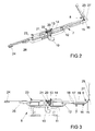
- FIG. 2 shows in perspective the fitting part 7 of Figure 1 with a pivotable closing part 10, which with a on the frame 1 attached strike plate 11 cooperates.
- FIG. 3 shows the fitting part 7 with the striking plate 11 in a view from below.
- the fitting part 7 has a common housing 12 for a bearing 13 of the pivotable closing part 10 and the corner 8 and is attached to the wing 2 shown in Figure 1.
- On the housing 12, a straight portion 14 of the drive rod 5 is longitudinally displaceable and a band 15 of the corner 8 guided.
- the housing 12 has to guide the belt 15 of the corner 8 a groove 16. The connection of the mutually facing ends of the belt 15 and the straight portion 14 via via a web 17 of the housing 12 guided coupling means 18.
- the web 17 has for this purpose a recess 19 for carrying out the coupling means 18.
- the closing part 10 is mounted on a bearing pin 20 fastened in the housing 12 and has a toothing 21, with which it is coupled with a toothing 22 of the straight portion 14 of the drive rod 5.
- the drive rod 5 has in the region of its toothing 22 a crank 23 and is slightly protruding in the region of the closing part 10.
- the housing 12 can also be used in very flat fitting grooves of the wing 2.
- FIGS. 2 and 3 show that the free end of the straight section 14 of the drive rod 5 and the free end of the band 15 of the corner drive 8 have connections 24, 25, to which further components of the drive rod fitting 3 shown in FIG.
- the housing 12 has flanges 26, 27 for connection of not shown, the drive rod 5 covering cuff rails.
- Figure 4 shows greatly enlarged the closing part 10 with adjacent areas of the straight portion 14 of the drive rod 5.
- the toothing 22 of the drive rod 5 is in engagement with the teeth 21 of the closing part 10, wherein the closing part 10 is shown in the out of the housing 12 out pivoted position.
- a designed as part of the teeth 22 of the straight portion 14 of the drive rod 5 blocking element 28 is in the range of movement formed as part of the teeth 21 of the closure member 10 projection 29.
- the closing part 10 At the teeth 22 of the straight portion 14 of the drive rod 5 is adjacent to a trained as a slot backlash 30 at.
- the closing part 10 When the teeth 21 of the closing part 10 penetrate into the backward passage 30, the closing part 10 is located inside the housing 12. Subsequently, the drive rod 5 can be displaced without the closing part 10 being further pivoted. This is often necessary to control other components of the espagnolette fitting 3 without movement of the closing part 10 and thus to move the wing 2 shown in Figure 1, for example in a tilted position.
Landscapes
- Engineering & Computer Science (AREA)
- Mechanical Engineering (AREA)
- Power-Operated Mechanisms For Wings (AREA)
- Snaps, Bayonet Connections, Set Pins, And Snap Rings (AREA)
- Mutual Connection Of Rods And Tubes (AREA)
- Fishing Rods (AREA)
- Shafts, Cranks, Connecting Bars, And Related Bearings (AREA)
Abstract
Description
- Die Erfindung betrifft ein Beschlagteil für einen Treibstangenbeschlag mit einer Eckumlenkung einer Treibstange und mit einem Schließteil, dessen Bewegung mit der Bewegung der Treibstange gekoppelt ist, mit zumindest einem geraden, mit einem flexiblen Band der Eckumlenkung verbundenen Abschnitt der Treibstange und mit zur Koppelung des freien Endes des Bandes und des geraden Abschnitts der Treibstange mit weiterführenden Bauteilen vorgesehenen Anschlüssen.
- Ein solches Beschlagteil ermöglicht die Anordnung von Schließteile aufweisenden Verschlüssen über den Umfang des den Treibstangenbeschlag aufweisenden Fensters und sind aus der Praxis bekannt. Bei den bekannten Beschlagteilen ist das Schließteil als in die Treibstange eingepresster Schließzapfen ausgebildet und durchdringt einen Abschnitt einer Stulpschiene durch ein Langloch. Das Schließteil hintergreift die Stulpschiene und bildet damit eine Führung für den Abschnitt der Treibstange. Die Stulpschiene ist mit einer aus einem gebogenen Blech gefertigten Führung für das Band der Eckumlenkung verbunden. Einander zugewandte Enden des Bandes und des Abschnitts der Treibstange sind ebenfalls miteinander verbunden. Der Vorteil dieses Beschlagteils besteht darin, dass sich die Eckumlenkung und das Schließteil unmittelbar nebeneinander anordnen und als vormontierte bauliche Einheit in dem Treibstangenbeschlag montieren lassen. Nachteilig ist jedoch, dass das Beschlagteil sehr aufwändig aufgebaut ist und eine aufwändige Montage erfordert.
- Weiterhin sind andere Schließteile als Schließzapfen nur mit großem Aufwand an dem Beschlagteil montierbar. Häufig ist es jedoch zur Erhöhung der Aufbruchssicherheit des Treibstangenbeschlages wünschenswert, die Schließteile als Schwenkriegel auszubilden.
- Der Erfindung liegt das Problem zugrunde, ein Beschlagteil der eingangs genannten Art so weiterzubilden, dass es möglichst einfach aufgebaut ist und eine hohe Aufbruchssicherheit bietet.
- Dieses Problem wird erfindungsgemäß dadurch gelöst, dass ein gemeinsames einstückiges Gehäuse den geraden Abschnitt und das Band der Eckumlenkung aufnimmt und dass das Schließteil schwenkbar in dem Gehäuse gelagert ist.
- Durch diese Gestaltung sind die Führung des Bandes der Eckumlenkung und eine Führung für das Schließteil über das Gehäuse miteinander verbunden. Dies führt zunächst zu einer besonders genauen Positionierung der Bauteile zueinander und zu einem einfachen Aufbau des erfindungsgemäßen Beschlagteils. Weiterhin wird das Schließteil von dem Gehäuse schwenkbar geführt, so dass das erfindungsgemäße Beschlagteil eine besonders hohe Aufbruchssicherheit bietet. Weiterhin weist das erfindungsgemäße Beschlagteil eine besonders geringe Anzahl von Bauteilen auf und lässt sich daher besonders einfach montieren.
- Das Gehäuse weist gemäß einer vorteilhaften Weiterbildung der Erfindung eine hohe Stabilität auf und lässt sich kostengünstig in einer Großserie fertigen, wenn das gemeinsame Gehäuse aus Leichtmetall, insbesondere Zinkdruckguss gefertigt ist und eine bogenförmige Nut zur Aufnahme des Bandes der Eckumlenkung hat. Vorzugsweise wird das aus Leichtmetall gefertigte Gehäuse kostengünstig im Spritzgussverfahren gefertigt.
- Die Führungen des geraden Abschnitts der Treibstange und des Bandes der Eckumlenkung erfordern gemäß einer anderen vorteilhaften Weiterbildung der Erfindung einen besonders geringen baulichen Aufwand, wenn das gemeinsame Gehäuse einen parallel zum Bewegungsbereich der Treibstange angeordneten Steg aufweist, wenn auf einer Seite des Steges die Nut zur Aufnahme des Bandes angeordnet und auf der anderen Seite ein Ende des geraden Abschnitts der Treibstange geführt ist und wenn das Band und der gerade Abschnitt über ein Koppelmittel miteinander verbunden sind.
- Das erfindungsgemäße Beschlagteil gestaltet sich besonders kompakt, wenn der Steg eine Ausnehmung aufweist und wenn das Koppelmittel die Ausnehmung durchdringt. Vorzugsweise ist die Ausnehmung ein Langloch und erzeugt damit eine Führung für das Koppelmittel.
- Das erfindungsgemäße Beschlagteil lässt sich für unterschiedliche Abmessungen einer Beschlagnut anpassen, wenn der gerade Abschnitt der Treibstange im Bereich des schwenkbaren Schließteils gekröpft ist. Hierdurch kann die Kröpfung bis zu dem Boden der Beschlagnut geführt und das Schließteil mit entsprechenden Abmessungen versehen werden.
- Das erfindungsgemäße Beschlagteil lässt sich auch in besonders niedrigen Beschlagnuten einsetzen, wenn das Gehäuse im Bereich des Schließteils hervorsteht.
- Eine Selbsthemmung des Schließteils lässt sich gemäß einer anderen vorteilhaften Weiterbildung der Erfindung einfach erreichen, wenn die Treibstange ein Blockierelement aufweist und wenn das Blockierelement in der heraus geschwenkten Stellung des Schließteils einen Vorsprung des schwenkbaren Schließteils hintergreift. Durch die Selbsthemmung wird verhindert, dass das Schließteil von außen in das Gehäuse zurück gedrückt werden kann. Dies trägt zur weiteren Erhöhung der Aufbruchssicherheit des mit dem erfindungsgemäßen Beschlagteil ausgestatteten Treibstangenbeschlages bei.
- Der bauliche Aufwand für die selbsthemmende Gestaltung des Schließteils lässt sich gemäß einer anderen vorteilhaften Weiterbildung der Erfindung besonders gering halten, wenn das Blockierelement einstückig mit der Treibstange gefertigt ist und der Vorsprung Teil einer beim Antrieb des Schließteils mit einer Verzahnung der Treibstange in Eingriff stehenden Verzahnung des Schließteils ist.
- Zur Vereinfachung der Montage des erfindungsgemäßen Beschlagteils trägt es bei, wenn das Gehäuse eine Abdeckung aufweist und wenn die Abdeckung und das Gehäuse einander gegenüberstehende Ausnehmungen für eine Lagerung des Schließteils aufweisen. Die Abdeckung erhöht zudem die Stabilität des Gehäuses.
- Ein Verklemmen des Schließteils durch eine axiale Verspannung des Gehäuses mit der Abdeckung lässt sich gemäß einer anderen vorteilhaften Weiterbildung der Erfindung einfach vermeiden, wenn die Lagerung des Schließteils einen in den Ausnehmungen der Abdeckung und des Gehäuses gehaltenen Lagerbolzen aufweisen und wenn das Schließteil auf dem Lagerbolzen gelagert ist.
- Zur Verbindung des erfindungsgemäßen Beschlagteils mit angrenzenden Bauteilen des Treibstangenbeschlages trägt es bei, wenn das Gehäuse zumindest einen Flansch zur Anbindung einer Stulpschiene hat.
- Die Erfindung lässt zahlreiche Ausführungsformen zu. Zur weiteren Verdeutlichung ihres Grundprinzips ist eine davon in der Zeichnung dargestellt und wird nachfolgend beschrieben. Diese zeigt in
- Fig. 1
- ein Fenster mit einem ein erfindungsgemäßes Beschlagteil aufweisenden Treibstangenbeschlag,
- Fig. 2
- das erfindungsgemäße Beschlagteil aus Figur 1 in einer perspektivischen Darstellung,
- Fig. 3
- das erfindungsgemäße Beschlagteil in einer Schließstellung,
- Fig. 4
- stark vergrößert eine perspektivische Darstellung eines Antriebs eines Schwenkteils des erfindungsgemäßen Beschlagteils
- Figur 1 zeigt ein Fenster mit einem gegen einen Rahmen 1 schwenkbaren Flügel 2. Das Fenster weist einen Treibstangenbeschlag 3 mit einer von einer Handhabe 4 antreibbaren Treibstange 5 auf. Die Treibstange 5 steuert einen Verschluss 6 zur Verriegelung des Flügels in dem Rahmen an. Der Verschluss 6 weist ein Beschlagteil 7 auf, welches eine bauliche Einheit mit einer Eckumlenkung 8 der Treibstange 5 bildet. Weiterhin weist der Treibstangenbeschlag 3 weitere Verschlüsse 9 auf, von denen beispielhaft einer dargestellt ist.
- Figur 2 zeigt perspektivisch das Beschlagteil 7 aus Figur 1 mit einem schwenkbaren Schließteil 10, welches mit einem an dem Rahmen 1 befestigten Schließblech 11 zusammenwirkt. Figur 3 zeigt das Beschlagteil 7 mit dem Schließblech 11 in einer Ansicht von unten. Das Beschlagteil 7 hat ein gemeinsames Gehäuse 12 für eine Lagerung 13 des schwenkbaren Schließteils 10 und der Eckumlenkung 8 und ist an dem in Figur 1 dargestellten Flügel 2 befestigt. An dem Gehäuse 12 ist ein gerader Abschnitt 14 der Treibstange 5 längsverschieblich und ein Band 15 der Eckumlenkung 8 geführt. Das Gehäuse 12 hat zur Führung des Bandes 15 der Eckumlenkung 8 eine Nut 16. Die Verbindung der einander zugewandten Enden des Bandes 15 und des geraden Abschnitts 14 erfolgt über durch einen Steg 17 des Gehäuses 12 geführte Koppelmittel 18. Der Steg 17 weist hierfür eine Ausnehmung 19 zur Durchführung der Koppelmittel 18 auf. Das Schließteil 10 ist auf einem in dem Gehäuse 12 befestigten Lagerbolzen 20 gelagert und weist eine Verzahnung 21 auf, mit der es mit einer Verzahnung 22 des geraden Abschnitts 14 der Treibstange 5 gekoppelt ist. Die Treibstange 5 hat im Bereich seiner Verzahnung 22 eine Kröpfung 23 und steht im Bereich des Schließteils 10 geringfügig hervor. Hierdurch lässt sich das Gehäuse 12 auch in sehr flachen Beschlagnuten des Flügels 2 einsetzen.
- Weiterhin zeigen Figur 2 und 3, dass das freie Ende des geraden Abschnitts 14 der Treibstange 5 und das freie Ende des Bandes 15 der Eckumlenkung 8 Anschlüsse 24, 25 aufweisen, an denen sich weiterführende Bauteile des in Figur 1 dargestellten Treibstangenbeschlages 3 anschließen lassen. Das Gehäuse 12 weist Flansche 26, 27 zum Anschluss von nicht dargestellten, die Treibstange 5 abdeckenden Stulpschienen auf.
- Figur 4 zeigt stark vergrößert das Schließteil 10 mit angrenzenden Bereichen des geraden Abschnitts 14 der Treibstange 5. Die Verzahnung 22 der Treibstange 5 steht im Eingriff mit der Verzahnung 21 des Schließteils 10, wobei das Schließteil 10 in der aus dem Gehäuse 12 heraus geschwenkten Lage dargestellt ist. Ein als Teil der Verzahnung 22 des geraden Abschnitts 14 der Treibstange 5 ausgebildetes Blockierelement 28 steht im Bewegungsbereich eines als Teil der Verzahnung 21 des Schließteils 10 ausgebildeten Vorsprungs 29. Damit lässt sich das Schließteil 10 ohne vorherige Bewegung der Treibstange 5 nicht in das Gehäuse 12 zurück drücken. Bei einem Antrieb der Treibstange 5 hingegen wirken die Verzahnungen 21, 22 des geraden Abschnitts 14 der Treibstange 5 und des Schließteils 10 derart zusammen, dass das Schließteil 10 in das Gehäuse 12 zurück geschwenkt wird. An die Verzahnung 22 des geraden Abschnitts 14 der Treibstange 5 grenzt ein als Langloch ausgebildeter Leergang 30 an. Wenn die Verzahnung 21 des Schließteils 10 in den Leergang 30 eindringt, befindet sich das Schließteil 10 innerhalb des Gehäuses 12. Anschließend lässt sich die Treibstange 5 verschieben, ohne dass das Schließteil 10 weiter verschwenkt wird. Dies ist häufig erforderlich, um weitere Bauteile des Treibstangenbeschlages 3 ohne Bewegung des Schließteils 10 anzusteuern und damit den in Figur 1 dargestellten Flügel 2 beispielsweise in eine Kippstellung zu bewegen.
Claims (11)
- Beschlagteil für einen Treibstangenbeschlag mit einer Eckumlenkung einer Treibstange und mit einem Schließteil, dessen Bewegung mit der Bewegung der Treibstange gekoppelt ist, mit zumindest einem geraden, mit einem flexiblen Band der Eckumlenkung verbundenen Abschnitt der Treibstange und mit zur Koppelung des freien Endes des Bandes und des geraden Abschnitts der Treibstange mit weiterführenden Bauteilen vorgesehenen Anschlüssen, dadurch gekennzeichnet, dass ein gemeinsames einstückiges Gehäuse (12) den geraden Abschnitt (14) und das Band (15) der Eckumlenkung (8) aufnimmt und dass das Schließteil (10) schwenkbar in dem Gehäuse (12) gelagert ist
- Beschlagteil nach Anspruch 1, dadurch gekennzeichnet, dass das gemeinsame Gehäuse (12) aus Leichtmetall, insbesondere Zinkdruckguss gefertigt ist und eine bogenförmige Nut (16) zur Aufnahme des Bandes (15) der Eckumlenkung (8) hat.
- Beschlagteil nach Anspruch 2, dadurch gekennzeichnet, dass das gemeinsame Gehäuse (12) einen parallel zum Bewegungsbereich der Treibstange (5) angeordneten Steg (17) aufweist, dass auf einer Seite des Steges (17) die Nut (16) zur Aufnahme des Bandes (15) angeordnet und auf der anderen Seite ein Ende des geraden Abschnitts (14) der Treibstange (5) geführt ist und dass das Band (15) und der gerade Abschnitt (14) über ein Koppelmittel (18) miteinander verbunden sind.
- Beschlagteil nach Anspruch 3, dadurch gekennzeichnet, dass der Steg (17) eine Ausnehmung (19) aufweist und dass das Koppelmittel (18) die Ausnehmung (19) durchdringt.
- Beschlagteil nach Anspruch 1, dadurch gekennzeichnet, dass der gerade Abschnitt (14) der Treibstange (5) im Bereich des schwenkbaren Schließteils (10) gekröpft ist.
- Beschlagteil nach Anspruch 1, dadurch gekennzeichnet, dass das Gehäuse (12) im Bereich des Schließteils (10) hervorsteht.
- Beschlagteil nach Anspruch 1, dadurch gekennzeichnet, dass die Treibstange (5) ein Blockierelement (28) aufweist und dass das Blockierelement (28) in der heraus geschwenkten Stellung des Schließteils (10) einen Vorsprung (29) des schwenkbaren Schließteils (10) hintergreift.
- Beschlagteil nach Anspruch 7, dadurch gekennzeichnet, dass das Blockierelement (28) einstückig mit der Treibstange (5) gefertigt ist und der Vorsprung (29) Teil einer beim Antrieb des schwenkbaren Schließteils (10) mit einer Verzahnung (22) der Treibstange (5) in Eingriff stehenden Verzahnung (21) des Schließteils (10) ist.
- Beschlagteil nach Anspruch 1, dadurch gekennzeichnet, dass das Gehäuse (12) eine Abdeckung aufweist und dass die Abdeckung und das Gehäuse (12) einander gegenüberstehende Ausnehmungen (19) für eine Lagerung (13) des Schließteils (10) aufweisen.
- Beschlagteil nach Anspruch 9, dadurch gekennzeichnet, dass die Lagerung (13) des Schließteils (10) einen in den Ausnehmungen (19) der Abdeckung und des Gehäuses (12) gehaltenen Lagerbolzen (20) aufweist und dass das Schließteil (10) auf dem Lagerbolzen (20) gelagert ist.
- Beschlagteil nach Anspruch 1, dadurch gekennzeichnet, dass das Gehäuse (12) zumindest einen Flansch (26, 27) zur Anbindung einer Stulpschiene hat.
Applications Claiming Priority (1)
| Application Number | Priority Date | Filing Date | Title |
|---|---|---|---|
| DE102005002909A DE102005002909A1 (de) | 2005-01-21 | 2005-01-21 | Beschlagteil für einen Treibstangenbeschlag |
Publications (2)
| Publication Number | Publication Date |
|---|---|
| EP1726756A1 true EP1726756A1 (de) | 2006-11-29 |
| EP1726756B1 EP1726756B1 (de) | 2008-05-28 |
Family
ID=36650522
Family Applications (1)
| Application Number | Title | Priority Date | Filing Date |
|---|---|---|---|
| EP05112103A Expired - Lifetime EP1726756B1 (de) | 2005-01-21 | 2005-12-14 | Beschlagteil für einen Treibstangenbeschlag |
Country Status (3)
| Country | Link |
|---|---|
| EP (1) | EP1726756B1 (de) |
| AT (1) | ATE397137T1 (de) |
| DE (2) | DE102005002909A1 (de) |
Families Citing this family (1)
| Publication number | Priority date | Publication date | Assignee | Title |
|---|---|---|---|---|
| DE102011003371A1 (de) * | 2011-01-31 | 2012-08-02 | Roto Frank Ag | Verriegelungsanordnung für Fenster, Türen oder dergleichen mit einem Schwenkriegel |
Citations (4)
| Publication number | Priority date | Publication date | Assignee | Title |
|---|---|---|---|---|
| DE7044611U (de) * | Fa C Fuhr | Umlenkbeschlag fur Fenster, Türen oder dergleichen | ||
| DE2227377A1 (de) * | 1972-06-06 | 1973-12-20 | Ver Baubeschlag Gretsch Co | Stellvorrichtung fuer die fluegel, insbesondere kipp-schwenkfluegel, von fenstern, tueren od. dgl |
| DE7406520U (de) * | 1974-06-20 | Gretsch & Co Gmbh | Eckumlenkung für Stellgestänge bei Fenstern, Türen oder dergleichen | |
| EP1030017A1 (de) * | 1999-02-17 | 2000-08-23 | Ferco International Ferrures et Serrures de Bâtiment | Treibstangenschloss enthaltend einen Hakenriegel mit Mitteln zur Riegelblockierung |
Family Cites Families (3)
| Publication number | Priority date | Publication date | Assignee | Title |
|---|---|---|---|---|
| GB9408401D0 (en) * | 1994-04-28 | 1994-06-22 | Parkes Josiah & Sons Ltd | Locks |
| ATE522686T1 (de) * | 2001-02-12 | 2011-09-15 | Hautau Gmbh | Gesteuerte verriegelungsvorrichtung und eckumlenkung |
| DE10359803A1 (de) * | 2003-12-19 | 2005-07-14 | Aug. Winkhaus Gmbh & Co. Kg | Treibstangenschloss |
-
2005
- 2005-01-21 DE DE102005002909A patent/DE102005002909A1/de not_active Withdrawn
- 2005-12-14 EP EP05112103A patent/EP1726756B1/de not_active Expired - Lifetime
- 2005-12-14 AT AT05112103T patent/ATE397137T1/de active
- 2005-12-14 DE DE502005004271T patent/DE502005004271D1/de not_active Expired - Lifetime
Patent Citations (4)
| Publication number | Priority date | Publication date | Assignee | Title |
|---|---|---|---|---|
| DE7044611U (de) * | Fa C Fuhr | Umlenkbeschlag fur Fenster, Türen oder dergleichen | ||
| DE7406520U (de) * | 1974-06-20 | Gretsch & Co Gmbh | Eckumlenkung für Stellgestänge bei Fenstern, Türen oder dergleichen | |
| DE2227377A1 (de) * | 1972-06-06 | 1973-12-20 | Ver Baubeschlag Gretsch Co | Stellvorrichtung fuer die fluegel, insbesondere kipp-schwenkfluegel, von fenstern, tueren od. dgl |
| EP1030017A1 (de) * | 1999-02-17 | 2000-08-23 | Ferco International Ferrures et Serrures de Bâtiment | Treibstangenschloss enthaltend einen Hakenriegel mit Mitteln zur Riegelblockierung |
Also Published As
| Publication number | Publication date |
|---|---|
| DE102005002909A1 (de) | 2006-07-27 |
| DE502005004271D1 (de) | 2008-07-10 |
| ATE397137T1 (de) | 2008-06-15 |
| EP1726756B1 (de) | 2008-05-28 |
Similar Documents
| Publication | Publication Date | Title |
|---|---|---|
| EP1900891A2 (de) | Klapp-Hebelverschluss | |
| DE102017202797A1 (de) | Drehöffnungsbegrenzungsanordnung für ein Fenster oder eine Tür zur Begrenzung der Drehöffnungsbewegung eines Flügels eines Fensters oder einer Tür | |
| DE3645256C2 (de) | Fenster- und Türbeschlag | |
| DE4014041A1 (de) | Schliesszylinderbetaetigbares treibstangenschloss | |
| EP1726756B1 (de) | Beschlagteil für einen Treibstangenbeschlag | |
| EP2140087B1 (de) | Beschlag | |
| DE102007053340A1 (de) | Eckumlenkung für ein Treibstangenbeschlagsystem für einen Fenster- oder Türflügel | |
| DE102014216722B4 (de) | Steuerelement für eine Beschlaganordnung | |
| DE10216718A1 (de) | Türschloss | |
| EP0454958B1 (de) | Schloss, insbesondere Treibstangenschloss | |
| EP0828048A2 (de) | Schloss, insbesondere Einsteck-schloss | |
| DE19948862A1 (de) | Schließeinrichtung für einen Beschlag zur Verriegelung eines beweglichen Rahmenteils eines Fensters oder einer Tür | |
| EP2754804A2 (de) | Verschluss für einen Treibstangenbeschlag | |
| EP0930410B1 (de) | Betätigungshandhabe | |
| DE102004060717B4 (de) | Verschluss zur Verriegelung eines Flügels in einem Rahmen eines Fensters | |
| DE1964842A1 (de) | Beschlag fuer Fenster,Tueren u.dgl. | |
| DE102006000327A1 (de) | Verschluss für einen Treibstangenbeschlag eines Fensters | |
| DE8515071U1 (de) | Treibstangengetriebe für Fenster-, Tür- od.dgl. -flügel | |
| EP1798360B1 (de) | Beschlagteil für einen Treibstangenbeschlag | |
| EP3118401A1 (de) | Kantriegel | |
| DE10015095A1 (de) | Verriegelungsvorrichtung für einen Türflügel | |
| EP3322872B1 (de) | Verbindungseinrichtung sowie fenster oder tür mit einer verbindungseinrichtung | |
| DE102019209093A1 (de) | Antriebssystem für einen Flügel | |
| EP1746235A2 (de) | Beschlaganordnung | |
| EP1790805B1 (de) | Hebelgetriebe für einen Treibstangenbeschlag |
Legal Events
| Date | Code | Title | Description |
|---|---|---|---|
| PUAI | Public reference made under article 153(3) epc to a published international application that has entered the european phase |
Free format text: ORIGINAL CODE: 0009012 |
|
| AK | Designated contracting states |
Kind code of ref document: A1 Designated state(s): AT BE BG CH CY CZ DE DK EE ES FI FR GB GR HU IE IS IT LI LT LU LV MC NL PL PT RO SE SI SK TR |
|
| AX | Request for extension of the european patent |
Extension state: AL BA HR MK YU |
|
| 17P | Request for examination filed |
Effective date: 20070412 |
|
| AKX | Designation fees paid |
Designated state(s): AT BE BG CH CY CZ DE DK EE ES FI FR GB GR HU IE IS IT LI LT LU LV MC NL PL PT RO SE SI SK TR |
|
| GRAP | Despatch of communication of intention to grant a patent |
Free format text: ORIGINAL CODE: EPIDOSNIGR1 |
|
| GRAS | Grant fee paid |
Free format text: ORIGINAL CODE: EPIDOSNIGR3 |
|
| GRAA | (expected) grant |
Free format text: ORIGINAL CODE: 0009210 |
|
| AK | Designated contracting states |
Kind code of ref document: B1 Designated state(s): AT BE BG CH CY CZ DE DK EE ES FI FR GB GR HU IE IS IT LI LT LU LV MC NL PL PT RO SE SI SK TR |
|
| REG | Reference to a national code |
Ref country code: GB Ref legal event code: FG4D Free format text: NOT ENGLISH |
|
| RIN2 | Information on inventor provided after grant (corrected) |
Inventor name: KAUP, LUDGER Inventor name: SCHENCK, HANS-PETER Inventor name: BERNSMANN, WOLFGANG |
|
| REG | Reference to a national code |
Ref country code: CH Ref legal event code: EP |
|
| REF | Corresponds to: |
Ref document number: 502005004271 Country of ref document: DE Date of ref document: 20080710 Kind code of ref document: P |
|
| REG | Reference to a national code |
Ref country code: IE Ref legal event code: FG4D Free format text: LANGUAGE OF EP DOCUMENT: GERMAN |
|
| PG25 | Lapsed in a contracting state [announced via postgrant information from national office to epo] |
Ref country code: SI Free format text: LAPSE BECAUSE OF FAILURE TO SUBMIT A TRANSLATION OF THE DESCRIPTION OR TO PAY THE FEE WITHIN THE PRESCRIBED TIME-LIMIT Effective date: 20080528 |
|
| PG25 | Lapsed in a contracting state [announced via postgrant information from national office to epo] |
Ref country code: ES Free format text: LAPSE BECAUSE OF FAILURE TO SUBMIT A TRANSLATION OF THE DESCRIPTION OR TO PAY THE FEE WITHIN THE PRESCRIBED TIME-LIMIT Effective date: 20080908 Ref country code: FI Free format text: LAPSE BECAUSE OF FAILURE TO SUBMIT A TRANSLATION OF THE DESCRIPTION OR TO PAY THE FEE WITHIN THE PRESCRIBED TIME-LIMIT Effective date: 20080528 |
|
| PG25 | Lapsed in a contracting state [announced via postgrant information from national office to epo] |
Ref country code: NL Free format text: LAPSE BECAUSE OF FAILURE TO SUBMIT A TRANSLATION OF THE DESCRIPTION OR TO PAY THE FEE WITHIN THE PRESCRIBED TIME-LIMIT Effective date: 20080528 Ref country code: LV Free format text: LAPSE BECAUSE OF FAILURE TO SUBMIT A TRANSLATION OF THE DESCRIPTION OR TO PAY THE FEE WITHIN THE PRESCRIBED TIME-LIMIT Effective date: 20080528 |
|
| NLV1 | Nl: lapsed or annulled due to failure to fulfill the requirements of art. 29p and 29m of the patents act | ||
| PG25 | Lapsed in a contracting state [announced via postgrant information from national office to epo] |
Ref country code: IS Free format text: LAPSE BECAUSE OF FAILURE TO SUBMIT A TRANSLATION OF THE DESCRIPTION OR TO PAY THE FEE WITHIN THE PRESCRIBED TIME-LIMIT Effective date: 20080928 |
|
| REG | Reference to a national code |
Ref country code: IE Ref legal event code: FD4D |
|
| PG25 | Lapsed in a contracting state [announced via postgrant information from national office to epo] |
Ref country code: SE Free format text: LAPSE BECAUSE OF FAILURE TO SUBMIT A TRANSLATION OF THE DESCRIPTION OR TO PAY THE FEE WITHIN THE PRESCRIBED TIME-LIMIT Effective date: 20080828 Ref country code: IE Free format text: LAPSE BECAUSE OF FAILURE TO SUBMIT A TRANSLATION OF THE DESCRIPTION OR TO PAY THE FEE WITHIN THE PRESCRIBED TIME-LIMIT Effective date: 20080528 Ref country code: CZ Free format text: LAPSE BECAUSE OF FAILURE TO SUBMIT A TRANSLATION OF THE DESCRIPTION OR TO PAY THE FEE WITHIN THE PRESCRIBED TIME-LIMIT Effective date: 20080528 Ref country code: DK Free format text: LAPSE BECAUSE OF FAILURE TO SUBMIT A TRANSLATION OF THE DESCRIPTION OR TO PAY THE FEE WITHIN THE PRESCRIBED TIME-LIMIT Effective date: 20080528 Ref country code: LT Free format text: LAPSE BECAUSE OF FAILURE TO SUBMIT A TRANSLATION OF THE DESCRIPTION OR TO PAY THE FEE WITHIN THE PRESCRIBED TIME-LIMIT Effective date: 20080528 |
|
| PG25 | Lapsed in a contracting state [announced via postgrant information from national office to epo] |
Ref country code: RO Free format text: LAPSE BECAUSE OF FAILURE TO SUBMIT A TRANSLATION OF THE DESCRIPTION OR TO PAY THE FEE WITHIN THE PRESCRIBED TIME-LIMIT Effective date: 20080528 Ref country code: PT Free format text: LAPSE BECAUSE OF FAILURE TO SUBMIT A TRANSLATION OF THE DESCRIPTION OR TO PAY THE FEE WITHIN THE PRESCRIBED TIME-LIMIT Effective date: 20081028 Ref country code: SK Free format text: LAPSE BECAUSE OF FAILURE TO SUBMIT A TRANSLATION OF THE DESCRIPTION OR TO PAY THE FEE WITHIN THE PRESCRIBED TIME-LIMIT Effective date: 20080528 |
|
| PLBE | No opposition filed within time limit |
Free format text: ORIGINAL CODE: 0009261 |
|
| STAA | Information on the status of an ep patent application or granted ep patent |
Free format text: STATUS: NO OPPOSITION FILED WITHIN TIME LIMIT |
|
| PG25 | Lapsed in a contracting state [announced via postgrant information from national office to epo] |
Ref country code: EE Free format text: LAPSE BECAUSE OF FAILURE TO SUBMIT A TRANSLATION OF THE DESCRIPTION OR TO PAY THE FEE WITHIN THE PRESCRIBED TIME-LIMIT Effective date: 20080528 Ref country code: BG Free format text: LAPSE BECAUSE OF FAILURE TO SUBMIT A TRANSLATION OF THE DESCRIPTION OR TO PAY THE FEE WITHIN THE PRESCRIBED TIME-LIMIT Effective date: 20080828 |
|
| 26N | No opposition filed |
Effective date: 20090303 |
|
| BERE | Be: lapsed |
Owner name: AUG. WINKHAUS G.M.B.H. & CO. KG Effective date: 20081231 |
|
| PG25 | Lapsed in a contracting state [announced via postgrant information from national office to epo] |
Ref country code: MC Free format text: LAPSE BECAUSE OF NON-PAYMENT OF DUE FEES Effective date: 20081231 |
|
| PG25 | Lapsed in a contracting state [announced via postgrant information from national office to epo] |
Ref country code: IT Free format text: LAPSE BECAUSE OF FAILURE TO SUBMIT A TRANSLATION OF THE DESCRIPTION OR TO PAY THE FEE WITHIN THE PRESCRIBED TIME-LIMIT Effective date: 20080528 |
|
| PG25 | Lapsed in a contracting state [announced via postgrant information from national office to epo] |
Ref country code: BE Free format text: LAPSE BECAUSE OF NON-PAYMENT OF DUE FEES Effective date: 20081231 |
|
| PG25 | Lapsed in a contracting state [announced via postgrant information from national office to epo] |
Ref country code: PL Free format text: LAPSE BECAUSE OF FAILURE TO SUBMIT A TRANSLATION OF THE DESCRIPTION OR TO PAY THE FEE WITHIN THE PRESCRIBED TIME-LIMIT Effective date: 20080528 |
|
| PG25 | Lapsed in a contracting state [announced via postgrant information from national office to epo] |
Ref country code: LU Free format text: LAPSE BECAUSE OF NON-PAYMENT OF DUE FEES Effective date: 20081214 Ref country code: HU Free format text: LAPSE BECAUSE OF FAILURE TO SUBMIT A TRANSLATION OF THE DESCRIPTION OR TO PAY THE FEE WITHIN THE PRESCRIBED TIME-LIMIT Effective date: 20081129 Ref country code: CY Free format text: LAPSE BECAUSE OF FAILURE TO SUBMIT A TRANSLATION OF THE DESCRIPTION OR TO PAY THE FEE WITHIN THE PRESCRIBED TIME-LIMIT Effective date: 20080528 |
|
| REG | Reference to a national code |
Ref country code: CH Ref legal event code: PL |
|
| GBPC | Gb: european patent ceased through non-payment of renewal fee |
Effective date: 20091214 |
|
| PG25 | Lapsed in a contracting state [announced via postgrant information from national office to epo] |
Ref country code: TR Free format text: LAPSE BECAUSE OF FAILURE TO SUBMIT A TRANSLATION OF THE DESCRIPTION OR TO PAY THE FEE WITHIN THE PRESCRIBED TIME-LIMIT Effective date: 20080528 |
|
| PG25 | Lapsed in a contracting state [announced via postgrant information from national office to epo] |
Ref country code: GR Free format text: LAPSE BECAUSE OF FAILURE TO SUBMIT A TRANSLATION OF THE DESCRIPTION OR TO PAY THE FEE WITHIN THE PRESCRIBED TIME-LIMIT Effective date: 20080829 Ref country code: LI Free format text: LAPSE BECAUSE OF NON-PAYMENT OF DUE FEES Effective date: 20091231 Ref country code: CH Free format text: LAPSE BECAUSE OF NON-PAYMENT OF DUE FEES Effective date: 20091231 |
|
| PG25 | Lapsed in a contracting state [announced via postgrant information from national office to epo] |
Ref country code: GB Free format text: LAPSE BECAUSE OF NON-PAYMENT OF DUE FEES Effective date: 20091214 |
|
| REG | Reference to a national code |
Ref country code: FR Ref legal event code: PLFP Year of fee payment: 11 |
|
| PGFP | Annual fee paid to national office [announced via postgrant information from national office to epo] |
Ref country code: FR Payment date: 20151229 Year of fee payment: 11 Ref country code: AT Payment date: 20151228 Year of fee payment: 11 |
|
| REG | Reference to a national code |
Ref country code: AT Ref legal event code: MM01 Ref document number: 397137 Country of ref document: AT Kind code of ref document: T Effective date: 20161214 |
|
| REG | Reference to a national code |
Ref country code: FR Ref legal event code: ST Effective date: 20170831 |
|
| PG25 | Lapsed in a contracting state [announced via postgrant information from national office to epo] |
Ref country code: FR Free format text: LAPSE BECAUSE OF NON-PAYMENT OF DUE FEES Effective date: 20170102 Ref country code: AT Free format text: LAPSE BECAUSE OF NON-PAYMENT OF DUE FEES Effective date: 20161214 |
|
| PGFP | Annual fee paid to national office [announced via postgrant information from national office to epo] |
Ref country code: DE Payment date: 20210224 Year of fee payment: 16 |
|
| REG | Reference to a national code |
Ref country code: DE Ref legal event code: R119 Ref document number: 502005004271 Country of ref document: DE |
|
| PG25 | Lapsed in a contracting state [announced via postgrant information from national office to epo] |
Ref country code: DE Free format text: LAPSE BECAUSE OF NON-PAYMENT OF DUE FEES Effective date: 20220701 |