EP1726466A1 - Klimaanlage, insbesondere für ein Kraftfahrzeug - Google Patents
Klimaanlage, insbesondere für ein Kraftfahrzeug Download PDFInfo
- Publication number
- EP1726466A1 EP1726466A1 EP06010561A EP06010561A EP1726466A1 EP 1726466 A1 EP1726466 A1 EP 1726466A1 EP 06010561 A EP06010561 A EP 06010561A EP 06010561 A EP06010561 A EP 06010561A EP 1726466 A1 EP1726466 A1 EP 1726466A1
- Authority
- EP
- European Patent Office
- Prior art keywords
- air
- heater
- conditioning system
- air conditioning
- flap
- Prior art date
- Legal status (The legal status is an assumption and is not a legal conclusion. Google has not performed a legal analysis and makes no representation as to the accuracy of the status listed.)
- Granted
Links
Images

Classifications
-
- B—PERFORMING OPERATIONS; TRANSPORTING
- B60—VEHICLES IN GENERAL
- B60H—ARRANGEMENTS OF HEATING, COOLING, VENTILATING OR OTHER AIR-TREATING DEVICES SPECIALLY ADAPTED FOR PASSENGER OR GOODS SPACES OF VEHICLES
- B60H1/00—Heating, cooling or ventilating devices
- B60H1/00642—Control systems or circuits; Control members or indication devices for heating, cooling or ventilating devices
- B60H1/00814—Control systems or circuits characterised by their output, for controlling particular components of the heating, cooling or ventilating installation
- B60H1/00821—Control systems or circuits characterised by their output, for controlling particular components of the heating, cooling or ventilating installation the components being ventilating, air admitting or air distributing devices
- B60H1/00835—Damper doors, e.g. position control
- B60H1/00849—Damper doors, e.g. position control for selectively commanding the induction of outside or inside air
-
- B—PERFORMING OPERATIONS; TRANSPORTING
- B60—VEHICLES IN GENERAL
- B60H—ARRANGEMENTS OF HEATING, COOLING, VENTILATING OR OTHER AIR-TREATING DEVICES SPECIALLY ADAPTED FOR PASSENGER OR GOODS SPACES OF VEHICLES
- B60H3/00—Other air-treating devices
- B60H3/0085—Smell or pollution preventing arrangements
-
- B—PERFORMING OPERATIONS; TRANSPORTING
- B60—VEHICLES IN GENERAL
- B60H—ARRANGEMENTS OF HEATING, COOLING, VENTILATING OR OTHER AIR-TREATING DEVICES SPECIALLY ADAPTED FOR PASSENGER OR GOODS SPACES OF VEHICLES
- B60H3/00—Other air-treating devices
- B60H3/0085—Smell or pollution preventing arrangements
- B60H3/0092—Smell or pollution preventing arrangements in the interior of the HVAC unit, e.g. by spraying substances inside the unit
-
- B—PERFORMING OPERATIONS; TRANSPORTING
- B60—VEHICLES IN GENERAL
- B60H—ARRANGEMENTS OF HEATING, COOLING, VENTILATING OR OTHER AIR-TREATING DEVICES SPECIALLY ADAPTED FOR PASSENGER OR GOODS SPACES OF VEHICLES
- B60H1/00—Heating, cooling or ventilating devices
- B60H1/00007—Combined heating, ventilating, or cooling devices
- B60H1/00021—Air flow details of HVAC devices
- B60H2001/0015—Temperature regulation
- B60H2001/00178—Temperature regulation comprising an air passage from the HVAC box to the exterior of the cabin
Definitions
- the invention relates to an air conditioning system, in particular for a motor vehicle, according to the preamble of claim 1.
- an air conditioner in particular a Kraftfahimaschine air conditioning system, with at least one arranged in a housing heater, possibly also a heater, and an evaporator, wherein flaps for controlling the air flow and a vent opening are provided.
- a vent stale By providing a vent stale, odorous air from the housing of the air conditioner can be transported to the outside, so that they do not enter the vehicle interior when starting the air conditioner on the automotive ventilation system, whereby the comfort can be increased.
- This solution to the problem has the advantage over the conventional chemical solutions, which provide coatings or the like, that it is safe in terms of the environment.
- the vent is preferably controlled by a flap, wherein the control of the flap preferably in connection with the control of the fan motor (start the same) and with the regulation of the flaps for controlling the air flow through the bypass, so past the heater, and for controlling the air flow connected by the heater.
- the vent opening is preferably provided between the evaporator and the heater, so that a relatively small area of the housing, in which the evaporator is arranged, is affected and correspondingly little air has to be removed. Consequently, the air is quickly exchanged and the ventilation operation when starting the air conditioning can be quickly switched to normal operation.
- the vent opening on the flow side may also be arranged upstream of the evaporator or above or below the evaporator.
- a flap such as a blind flap, roll cassette or a wing flap is arranged, which regulates the flow of air through the heater.
- the vent opening is preferably connected via an air duct with the environment.
- This air duct is preferably formed by a part of the fresh air duct, which in the opposite direction to the fresh air operation of. Air conditioning is flowed through. This allows for optimal utilization of the installation space. For this purpose, however, a corresponding control of the fresh air / recirculation damper is required, so that it is automatically set to fresh air operation when the air conditioning system is started.
- a presently one-cell automotive air conditioning system 1 has, arranged in a housing 2, a blower 3, an evaporator 4 and a heater 5 arranged downstream of a fresh air and recirculating air duct F or U.
- the tempered by means of the evaporator 4 and possibly the heater 5 air is supplied to a mixing chamber in a conventional manner via air ducts (defrosting, ventilation and footwell) the vehicle interior.
- the regulation of the air duct i. the temperature of the air supplied to the vehicle interior, carried out in normal operation in a conventional manner by means of flaps, wherein a first flap 6 is provided for controlling the supply of fresh air and circulating air. Furthermore, a second flap 7 is provided, which regulates the air flow past the heater 5.
- a third flap 8 in the present case in the form of a blind flap with a roll cassette, is provided, which regulates the air flow through the heater 5.
- a side vent 9 is provided in the housing 2 in the area between the evaporator 4 and heater 5, which by means of a vent valve 10, in this case a kind of drum flap with side opening, can be closed in normal operation, which is opened to eliminate the stale, odorous air after a stoppage of the air conditioning 1 short term.
- a vent valve 10 in this case a kind of drum flap with side opening, can be closed in normal operation, which is opened to eliminate the stale, odorous air after a stoppage of the air conditioning 1 short term.
- both the second flap 7 and the third flap 8 are closed, so that the entire air passes through the vent opening 9 to the outside.
- the vent opening 9 is automatically closed and the flaps 7 and 8 take the position corresponding to the desired temperature.
- a multi-zone air conditioning system wherein each of the individual zones are separated from each other by the provision of partitions and divided, separately controllable flaps.
- the vent flaps one of which is provided per zone, coupled together.
Landscapes
- Engineering & Computer Science (AREA)
- Mechanical Engineering (AREA)
- Life Sciences & Earth Sciences (AREA)
- Atmospheric Sciences (AREA)
- Environmental & Geological Engineering (AREA)
- Physics & Mathematics (AREA)
- Thermal Sciences (AREA)
- Power Engineering (AREA)
- Air-Conditioning For Vehicles (AREA)
- Motor Or Generator Cooling System (AREA)
Abstract
Description
- Die Erfindung betrifft eine Klimaanlage, insbesondere für ein Kraftfahrzeug, gemäß dem Oberbegriff des Anspruchs 1.
- Bei Kraftfahrzeug-Klimaanlagen tritt das Problem auf, dass am Verdampfer der Klimaanlage, welcher eine möglichst große Oberfläche aufweist, um den Kühleffekt zu optimieren, die in der Luft enthaltene Feuchtigkeit kondensiert und sich Kondenswasser ansammelt. An den feuchten Oberflächen setzt sich auch Staub aus der Luft ab, so dass sich innerhalb kurzer Zeit Bakterien und Pilze ansiedeln. Diese führen zu einem unangenehmen Geruch, welcher unerwünscht ist.
- Aus der
DE 44 45 881 C2 ist ein Mittel zur Verhinderung von mikrobakteriellem Anwuchs an einer Oberfläche durch Aufbringung oder Bereitstellen einer den Anwuchs hemmenden oder verhindemden Substanz auf bzw an der Oberfläche bekannt, wobei als hemmende Substanz oder Wirkstoff ein Gesteinsmehl mit einem auf diesem abgeschiedenen oder gebundenen Katalysator verwendet wird. Als Katalysator wird bspw. Braunstein (Manganoxid), Palladium oder Ruthenium verwendet. - Aus der
EP 0 409 130 B1 ist ein Aluminium-Wärmetauscher bekannt, bei welchem zur Vermeidung von Bakterien Schutzfilme auf den Oberflächen vorgesehen sind. - Derartige Wärmetauscher sind jedoch relativ aufwendig in der Herstellung. Zudem sind die Beschichtungen nicht ungefährlich und verteuern gegebenenfalls eine Entsorgung des Wärmetauschers.
- Alternativ sind physikalische Verfahren zur Entkeimung bekannt, wie beispielsweise die Bestrahlung mit UV-Licht, jedoch sind diese ebenfalls kostenintensiv
- Es ist Aufgabe der Erfindung, eine verbesserte Klimaanlage zur Verfügung zu stellen.
- Diese Aufgabe wird gelöst durch eine Klimaanlage mit den Merkmalen des Anspruchs 1. Vorteilhafte Ausgestaltungen sind Gegenstand der Unteransprüche.
- Erfindungsgemäß ist eine Klimaanlage vorgesehen, insbesondere eine Kraftfahizeug-Klimaanlage, mit mindestens einem in einem Gehäuse angeordneten Heizer, ggf. auch einem Zuheizer, und einem Verdampfer, wobei Klappen zur Regelung des Luftstroms und eine Entlüftungsöffnung vorgesehen sind. Durch das Vorsehen einer Entlüftungsöffnung kann abgestandene, geruchsbehaftete Luft aus dem Gehäuse der Klimaanlage nach außen befördert werden, so dass sie beim Starten der Klimaanlage über das Kraftfahrzeug-Belüftungssystem nicht in den Fahrzeuginnenraum gelangt, wodurch der Komfort gesteigert werden kann. Diese Lösung des Problems hat gegenüber den herkömmlichen chemischen Lösungen, die Beschichtungen o. ä. vorsehen, den Vorteil, dass sie in Hinblick auf die Umwelt unbedenklich ist. Natürlich ist jedoch auch eine Kombination mit anderen Lösungen, bspw. mit hydrophoben oder ggf. hydrophilen Oberflächen, welche derart ausgebildet sind, dass sie das Kondenswasser rasch ableiten, möglich.
- Die Entlüftungsöffnung ist vorzugsweise durch eine Klappe regelbar, wobei die Regelung der Klappe vorzugsweise in Verbindung mit der Regelung des Gebläsemotors (Start desselben) und mit der Regelung der Klappen zur Regelung des Luftstroms durch den Bypass, also vorbei am Heizer, und zur Regelung des Luftstroms durch den Heizer verbunden ist.
- Die Entlüftungsöffnung ist vorzugsweise zwischen Verdampfer und Heizer vorgesehen, so dass ein relativ kleiner Bereich des Gehäuses, in welchem der Verdampfer angeordnet ist, betroffen ist und entsprechend wenig Luft abgeführt werden muss. Folglich ist die Luft schnell ausgetauscht und vom Entlüftungsbetrieb beim Anfahren der Klimaanlage kann schnell auf den Normalbetrieb umgestellt werden. Alternativ kann die Entlüftungsöffnung strömungsseitig auch vor dem Verdampfer beziehungsweise über oder unter dem Verdampfer angeordnet sein.
- Bevorzugt ist zwischen dem Verdampfer und dem Heizer eine Klappe, beispielsweise eine Jalousie-Klappe, Rollbandkassette oder eine Flügelklappe angeordnet, welche den Luftstrom durch den Heizer regelt.
- Die Entlüftungsöffnung ist vorzugsweise über einen Luftkanal mit der Umgebung verbunden. Dieser Luftkanal wird bevorzugt durch einen Teil des Frischluftkanals gebildet, welcher in entgegengesetzter Richtung zum Frischluftbetrieb der. Klimaanlage durchströmt wird. Dies ermöglicht eine optimale Ausnutzung des Bauraums Hierfür ist jedoch eine entsprechende Regelung der Frischluft/Umluftklappe erforderlich, so dass dieselbe beim Starten der Klimaanlage automatisch auf Frischluftbetrieb gestellt wird.
- Im Folgenden wird die Erfindung anhand eines Ausführungsbeispiels unter Bezugnahme auf die Zeichnung im Einzelnen erläutert. In der Zeichnung zeigen:
- Fig. 1
- eine schematische Schnittdarstellung einer erfindungsgemäßen Kraftfahrzeug-Klimaanlage gemäß dem Ausführungsbeispiel, und
- Fig. 2
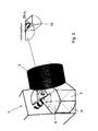
- eine perspektivische Darstellung des Klappenbereichs der Klimaanlage von Fig. 1 mit Detaildarstellung der Entlüftungsklappe.
- Eine vorliegend einzonige Kraftfahrzeug-Klimaanlage 1 weist in einem Gehäuse 2 angeordnet nach einem Frischluft- und Umluftkanal F bzw. U ein Gebläse 3, einen Verdampfer 4 und einen Heizer 5 auf. Die mit Hilfe des Verdampfers 4 und ggf. des Heizers 5 temperierte Luft wird nach einem Mischraum auf an sich bekannte Weise über Luftkanäle (Entfrostung, Belüftung und Fußraum) dem Fahrzeuginnenraum zugeführt.
- Die Regelung der Luftführung, d.h. die Temperierung der dem Fahrzeuginnenraum zuzuführenden Luft, erfolgt bei Normalbetrieb auf an sich bekannte Weise mittels Klappen, wobei eine erste Klappe 6 zur Regelung der Zufuhr von Frischluft und Umluft vorgesehen ist. Femer ist eine zweite Klappe 7 vorgesehen, welche den Luftstrom vorbei am Heizer 5 regelt. Vor dem Heizer 5 ist eine dritte Klappe 8, vorliegend in Form einer Jalousie-Klappe mit Rollbandkassette, vorgesehen, welche die Luftführung durch den Heizer 5 regelt.
- Um die abgestandene, geruchsbehaftete Luft im Verdampfer 4 beim Anfahren der Klimaanlage 1 zu beseitigen, ist im Gehäuse 2 eine seitliche Entlüftungsöffnung 9 im Bereich zwischen Verdampfer 4 und Heizer 5 vorgesehen, welche mittels einer Entlüftungsklappe 10, vorliegend einer Art Trommelklappe mit seitlicher Öffnung, im normalen Betrieb verschließbar ist, die jedoch zur Beseitigung der abgestandenen, geruchsbehafteten Luft nach einem Stillstand der Klimaanlage 1 kurzfristig geöffnet wird. Hierbei wird sowohl die zweite Klappe 7 als auch die dritte Klappe 8 geschlossen, so dass die gesamte Luft durch die Entlüftungsöffnung 9 nach außen gelangt. Nach einer vorgegebenen Zeit wird die Entlüftungsöffnung 9 automatisch geschlossen und die Klappen 7 und 8 nehmen die der gewünschten Temperatur entsprechende Stellung ein.
- Gemäß einer Variante ist eine mehrzonige Klimaanlage vorgesehen, wobei jeweils durch das Vorsehen von Trennwänden und unterteilten, getrennt regelbaren Klappen die einzelnen Zonen voneinander getrennt sind. Um jedoch bei einem Start der Klimaanlage eine vollständige Entlüftung derselben zu ermöglichen, sind die Entlüftungsklappen, von denen je eine je Zone vorgesehen ist, miteinander gekoppelt. Die Regelung der anderen Klappen, nämlich der zweiten Klappen, welche den Luftstrom vorbei am Heizer regeln, und der dritten Klappen, welche die Luftführung durch den Heizer regeln, erfolgt entsprechend dem ersten Ausführungsbeispiel.
Claims (13)
- Klimaanlage, insbesondere für Kraftfahrzeug-Klimaanlage, mit mindestens einem in einem Gehäuse (2) angeordneten Heizer (5) und einem Verdampfer (4), wobei Klappen (6, 7, 8) zur Regelung des Luftstroms vorgesehen sind, dadurch gekennzeichnet, dass im Gehäuse (2) eine Entlüftungsöffnung (9) vorgesehen ist.
- Klimaanlage nach Anspruch 1, dadurch gekennzeichnet, dass die Entlüftungsöffnung (9) durch eine Entlüftungsklappe (10) regelbar ist.
- Klimaanlage nach Anspruch 1 oder 2, dadurch gekennzeichnet, dass die Entlüftungsöffnung (9) zwischen Verdampfer (4) und Heizer (5) vorgesehen ist.
- Klimaanlage nach einem der vorhergehenden Ansprüche, dadurch gekennzeichnet, dass zwischen dem Verdampfer (4) und dem Heizer (5) eine Klappe (8) angeordnet ist.
- Klimaanlage nach Anspruch 4, dadurch gekennzeichnet, dass die Klappe (8) eine Jalousie-Klappe ist.
- Klimaanlage nach einem der vorhergehenden Ansprüche, dadurch gekennzeichnet, dass die Entlüftungsöffnung (9) über einen Luftkanal mit der Umgebung verbunden ist.
- Klimaanlage nach Anspruch 6, dadurch gekennzeichnet, dass der Luftkanal durch einen Teil des Frischluftkanals (F) gebildet ist.
- Klimaanlage nach einem der vorhergehenden Ansprüche, dadurch gekennzeichnet, dass die Regelung der Öffnung der Entlüftungsöffnung (9) mit der Regelung der Klappen (7, 8) zur Regelung des Luftstroms durch den Bypass vorbei am Heizer (5) und zur Regelung des Luftstroms durch den Heizer (5) derart verbunden sind, dass bei geöffneter Entlüftungsöffnung (9) die beiden anderen Klappen (7, 8) vollständig geschlossen sind.
- Verfahren zur Regelung einer Klimaanlage (1) nach einem der vorhergehenden Ansprüche, wobei die Entlüftungsöffnung (9) durch eine Entlüftungsklappe (10) geregelt wird, die bei Betriebsaufnahme der Klimaanlage (1) geöffnet wird.
- Verfahren nach Anspruch 9, dadurch gekennzeichnet, dass der gesamte den Verdampfer (4) durchströmende Luftstrom durch die Entlüftungsöffnung (9) bei geöffneter Entlüftungsklappe (10) geleitet wird.
- Verfahren nach Anspruch 9 oder 10, dadurch gekennzeichnet, dass die Entlüftungsklappe (10) zur Regelung der Öffnung der Entlüftungsöffnung (9) geöffnet und die Klappen (7, 8) zur Regelung des Luftstroms durch den Bypass vorbei am Heizer (5) und zur Regelung des Luftstroms durch den Heizer (5) geschlossen werden, sobald die Klimaanlage (1) gestartet wird, bevor das Gebläse (3) anläuft.
- Verfahren nach einem der Ansprüche 9 bis 11, dadurch gekennzeichnet, dass bei offener Entlüftungsöffnung (9) vom Gebläse (3) ausschließlich Luft aus dem Fahrzeuginnenraum angesaugt wird.
- Verfahren nach Anspruch 12, dadurch gekennzeichnet, dass die Luft aus dem Gehäuse (2) der Klimaanlage (1) über die Entlüftungsöffnung (9) über zumindest einen Teil des Frischluftkanals (F) nach außen geleitet wird.
Applications Claiming Priority (1)
| Application Number | Priority Date | Filing Date | Title |
|---|---|---|---|
| DE102005024446A DE102005024446A1 (de) | 2005-05-24 | 2005-05-24 | Klimaanlage, insbesondere für ein Kraftfahrzeug |
Publications (2)
| Publication Number | Publication Date |
|---|---|
| EP1726466A1 true EP1726466A1 (de) | 2006-11-29 |
| EP1726466B1 EP1726466B1 (de) | 2008-07-23 |
Family
ID=36688063
Family Applications (1)
| Application Number | Title | Priority Date | Filing Date |
|---|---|---|---|
| EP06010561A Expired - Lifetime EP1726466B1 (de) | 2005-05-24 | 2006-05-23 | Klimaanlage, insbesondere für ein Kraftfahrzeug |
Country Status (3)
| Country | Link |
|---|---|
| EP (1) | EP1726466B1 (de) |
| AT (1) | ATE402032T1 (de) |
| DE (2) | DE102005024446A1 (de) |
Cited By (2)
| Publication number | Priority date | Publication date | Assignee | Title |
|---|---|---|---|---|
| CN106240299A (zh) * | 2016-08-25 | 2016-12-21 | 安徽江淮松芝空调有限公司 | 一种弧形隔热及风向调节的风门结构 |
| CN111823827A (zh) * | 2020-07-20 | 2020-10-27 | 华域三电汽车空调有限公司 | 汽车空调紫外线灯消毒的控制方法、控制装置及存储介质 |
Citations (6)
| Publication number | Priority date | Publication date | Assignee | Title |
|---|---|---|---|---|
| EP0409130B1 (de) | 1989-07-17 | 1994-04-13 | Nippondenso Co., Ltd. | Aluminium-Wärmetauscher und Verfahren zu dessen Herstellung |
| US5983659A (en) * | 1996-09-23 | 1999-11-16 | Valeo Climatisation | Method and apparatus for evacuating bad smells for an air conditioning installation for a motor vehicle |
| DE4445881C2 (de) | 1994-12-22 | 2003-04-17 | Gradl Grams Marianne | Mittel zur Verhinderung von mikrobiellem Wachstum an Oberflächen |
| US20040003602A1 (en) * | 2002-03-23 | 2004-01-08 | Wolfgang Straub | Air conditioning system for a motor vehicle |
| DE10258025A1 (de) * | 2002-12-12 | 2004-07-08 | Daimlerchrysler Ag | Klimaanlage |
| FR2858269A1 (fr) * | 2003-07-29 | 2005-02-04 | Bosch Gmbh Robert | Installation de climatisation d'un vehicule et procede de commande de cette installation |
Family Cites Families (4)
| Publication number | Priority date | Publication date | Assignee | Title |
|---|---|---|---|---|
| DE2659683A1 (de) * | 1976-12-30 | 1978-07-20 | Siemens Ag | Heiz- und belueftungsvorrichtung fuer ein fahrzeug |
| KR960013745U (ko) * | 1994-10-12 | 1996-05-17 | 자동차의 공조장치 | |
| GB9503490D0 (en) * | 1995-02-22 | 1995-04-12 | Draftex Ind Ltd | Air extractor valve |
| DE10359064B3 (de) * | 2003-12-17 | 2005-03-10 | Daimler Chrysler Ag | Kühlungseinrichtung zur Kühlung elektronischer Bauteile in einem Kraftfahrzeug |
-
2005
- 2005-05-24 DE DE102005024446A patent/DE102005024446A1/de not_active Withdrawn
-
2006
- 2006-05-23 AT AT06010561T patent/ATE402032T1/de not_active IP Right Cessation
- 2006-05-23 DE DE502006001166T patent/DE502006001166D1/de not_active Expired - Lifetime
- 2006-05-23 EP EP06010561A patent/EP1726466B1/de not_active Expired - Lifetime
Patent Citations (6)
| Publication number | Priority date | Publication date | Assignee | Title |
|---|---|---|---|---|
| EP0409130B1 (de) | 1989-07-17 | 1994-04-13 | Nippondenso Co., Ltd. | Aluminium-Wärmetauscher und Verfahren zu dessen Herstellung |
| DE4445881C2 (de) | 1994-12-22 | 2003-04-17 | Gradl Grams Marianne | Mittel zur Verhinderung von mikrobiellem Wachstum an Oberflächen |
| US5983659A (en) * | 1996-09-23 | 1999-11-16 | Valeo Climatisation | Method and apparatus for evacuating bad smells for an air conditioning installation for a motor vehicle |
| US20040003602A1 (en) * | 2002-03-23 | 2004-01-08 | Wolfgang Straub | Air conditioning system for a motor vehicle |
| DE10258025A1 (de) * | 2002-12-12 | 2004-07-08 | Daimlerchrysler Ag | Klimaanlage |
| FR2858269A1 (fr) * | 2003-07-29 | 2005-02-04 | Bosch Gmbh Robert | Installation de climatisation d'un vehicule et procede de commande de cette installation |
Cited By (3)
| Publication number | Priority date | Publication date | Assignee | Title |
|---|---|---|---|---|
| CN106240299A (zh) * | 2016-08-25 | 2016-12-21 | 安徽江淮松芝空调有限公司 | 一种弧形隔热及风向调节的风门结构 |
| CN111823827A (zh) * | 2020-07-20 | 2020-10-27 | 华域三电汽车空调有限公司 | 汽车空调紫外线灯消毒的控制方法、控制装置及存储介质 |
| CN111823827B (zh) * | 2020-07-20 | 2023-01-03 | 华域三电汽车空调有限公司 | 汽车空调紫外线灯消毒的控制方法、控制装置及存储介质 |
Also Published As
| Publication number | Publication date |
|---|---|
| DE102005024446A1 (de) | 2006-11-30 |
| DE502006001166D1 (de) | 2008-09-04 |
| ATE402032T1 (de) | 2008-08-15 |
| EP1726466B1 (de) | 2008-07-23 |
Similar Documents
| Publication | Publication Date | Title |
|---|---|---|
| DE60225979T3 (de) | Vorrichtung zur Erzeugung einer temperaturgeregelten Luftströmung für einen Kraftfahrzeugfahrgastraum und Heizungs- und/oder Klimaanlage mit einer solchen Steuerungsvorrichtung | |
| EP1902876B1 (de) | Luftführungsgehäuse, insbesondere für eine Kraftfahrzeug-Klimaanlage, mit einer Verteilerklappe und Verfahren zur Regelung einer derartigen Verteilerklappe | |
| DE69301785T2 (de) | Vorrichtung für die Heizung, Lüftung und/oder Klimatisierung eines Fahrzeuginnenraumes | |
| EP1682367B1 (de) | Trommelklappe | |
| DE102015110559B4 (de) | Luftverteilungssystem für die dritte und/oder vierte Zone eines Drei- oder Vierzonen-Kraftfahrzeugklimagerätes | |
| DE112014004815T5 (de) | Heizungs-, Lüftungs- und/oder Klimaanlage für einen Kraftfahrzeugfahrgastraum | |
| EP1726466B1 (de) | Klimaanlage, insbesondere für ein Kraftfahrzeug | |
| DE102016116925B4 (de) | Fahrzeug-Beheizungs-, -Belüftungs- und Luftkühlungs-System | |
| EP1937500B1 (de) | Regelvorrichtung für ein kraftfahrzeug und verfahren zur regelung | |
| DE102012214859A1 (de) | Klimaanlage, insbesondere für ein Kraftfahrzeug | |
| DE10031534B4 (de) | Innenraumheiz- und/oder Klimaanlage, insbesondere für ein Kraftfahrzeug, mit Querkanal | |
| EP1426213A2 (de) | Klimagerät für Fahrzeuge | |
| DE10235526A1 (de) | Verfahren zur Steuerung/Regelung einer Belüftungseinrichtung einer Heiz-und/oder Klimaanlage | |
| DE102007049340A1 (de) | Kraftfahrzeug-Klimaanlagenanordnung | |
| DE2634713A1 (de) | Verfahren und vorrichtung zum beheizen und belueften des innenraums von omnibussen | |
| EP3065993B1 (de) | Verfahren zur klimatisierung eines fahrzeugs, insbesondere eines schienenfahrzeugs | |
| DE2101914C2 (de) | Klimaanlage für Fahrzeuge | |
| EP2277728B1 (de) | Klimaanlage | |
| DE102009060902B4 (de) | Klimatisieren eines Innenraums eines Fahrzeugs mit einer Umlufteinrichtung | |
| EP1843908B2 (de) | Kraftfahrzeug-klimaanlage | |
| DE102024106861B3 (de) | Luftausströmersystem für ein fahrzeug | |
| EP1724533B1 (de) | Raumlufttechnische Anlage sowie entsprechendes Verfahren | |
| WO2014012897A2 (de) | Klimaanlage | |
| CH626296A5 (en) | Method and device for conditioning the air of the interior of buses | |
| DE10314803B4 (de) | Verfahren zum Entfeuchten und Temperieren eines Luftstromes |
Legal Events
| Date | Code | Title | Description |
|---|---|---|---|
| PUAI | Public reference made under article 153(3) epc to a published international application that has entered the european phase |
Free format text: ORIGINAL CODE: 0009012 |
|
| AK | Designated contracting states |
Kind code of ref document: A1 Designated state(s): AT BE BG CH CY CZ DE DK EE ES FI FR GB GR HU IE IS IT LI LT LU LV MC NL PL PT RO SE SI SK TR |
|
| AX | Request for extension of the european patent |
Extension state: AL BA HR MK YU |
|
| 17P | Request for examination filed |
Effective date: 20070529 |
|
| 17Q | First examination report despatched |
Effective date: 20070704 |
|
| AKX | Designation fees paid |
Designated state(s): AT BE BG CH CY CZ DE DK EE ES FI FR GB GR HU IE IS IT LI LT LU LV MC NL PL PT RO SE SI SK TR |
|
| GRAP | Despatch of communication of intention to grant a patent |
Free format text: ORIGINAL CODE: EPIDOSNIGR1 |
|
| GRAS | Grant fee paid |
Free format text: ORIGINAL CODE: EPIDOSNIGR3 |
|
| GRAA | (expected) grant |
Free format text: ORIGINAL CODE: 0009210 |
|
| AK | Designated contracting states |
Kind code of ref document: B1 Designated state(s): AT BE BG CH CY CZ DE DK EE ES FI FR GB GR HU IE IS IT LI LT LU LV MC NL PL PT RO SE SI SK TR |
|
| REG | Reference to a national code |
Ref country code: GB Ref legal event code: FG4D Free format text: NOT ENGLISH |
|
| REG | Reference to a national code |
Ref country code: CH Ref legal event code: EP |
|
| REG | Reference to a national code |
Ref country code: IE Ref legal event code: FG4D Free format text: LANGUAGE OF EP DOCUMENT: GERMAN |
|
| REF | Corresponds to: |
Ref document number: 502006001166 Country of ref document: DE Date of ref document: 20080904 Kind code of ref document: P |
|
| NLV1 | Nl: lapsed or annulled due to failure to fulfill the requirements of art. 29p and 29m of the patents act | ||
| PG25 | Lapsed in a contracting state [announced via postgrant information from national office to epo] |
Ref country code: IS Free format text: LAPSE BECAUSE OF FAILURE TO SUBMIT A TRANSLATION OF THE DESCRIPTION OR TO PAY THE FEE WITHIN THE PRESCRIBED TIME-LIMIT Effective date: 20081123 Ref country code: NL Free format text: LAPSE BECAUSE OF FAILURE TO SUBMIT A TRANSLATION OF THE DESCRIPTION OR TO PAY THE FEE WITHIN THE PRESCRIBED TIME-LIMIT Effective date: 20080723 Ref country code: LT Free format text: LAPSE BECAUSE OF FAILURE TO SUBMIT A TRANSLATION OF THE DESCRIPTION OR TO PAY THE FEE WITHIN THE PRESCRIBED TIME-LIMIT Effective date: 20080723 |
|
| PG25 | Lapsed in a contracting state [announced via postgrant information from national office to epo] |
Ref country code: FI Free format text: LAPSE BECAUSE OF FAILURE TO SUBMIT A TRANSLATION OF THE DESCRIPTION OR TO PAY THE FEE WITHIN THE PRESCRIBED TIME-LIMIT Effective date: 20080723 Ref country code: BG Free format text: LAPSE BECAUSE OF FAILURE TO SUBMIT A TRANSLATION OF THE DESCRIPTION OR TO PAY THE FEE WITHIN THE PRESCRIBED TIME-LIMIT Effective date: 20081023 Ref country code: PT Free format text: LAPSE BECAUSE OF FAILURE TO SUBMIT A TRANSLATION OF THE DESCRIPTION OR TO PAY THE FEE WITHIN THE PRESCRIBED TIME-LIMIT Effective date: 20081223 Ref country code: ES Free format text: LAPSE BECAUSE OF FAILURE TO SUBMIT A TRANSLATION OF THE DESCRIPTION OR TO PAY THE FEE WITHIN THE PRESCRIBED TIME-LIMIT Effective date: 20081103 Ref country code: LV Free format text: LAPSE BECAUSE OF FAILURE TO SUBMIT A TRANSLATION OF THE DESCRIPTION OR TO PAY THE FEE WITHIN THE PRESCRIBED TIME-LIMIT Effective date: 20080723 Ref country code: SI Free format text: LAPSE BECAUSE OF FAILURE TO SUBMIT A TRANSLATION OF THE DESCRIPTION OR TO PAY THE FEE WITHIN THE PRESCRIBED TIME-LIMIT Effective date: 20080723 |
|
| REG | Reference to a national code |
Ref country code: IE Ref legal event code: FD4D |
|
| PG25 | Lapsed in a contracting state [announced via postgrant information from national office to epo] |
Ref country code: IE Free format text: LAPSE BECAUSE OF FAILURE TO SUBMIT A TRANSLATION OF THE DESCRIPTION OR TO PAY THE FEE WITHIN THE PRESCRIBED TIME-LIMIT Effective date: 20080723 Ref country code: EE Free format text: LAPSE BECAUSE OF FAILURE TO SUBMIT A TRANSLATION OF THE DESCRIPTION OR TO PAY THE FEE WITHIN THE PRESCRIBED TIME-LIMIT Effective date: 20080723 Ref country code: DK Free format text: LAPSE BECAUSE OF FAILURE TO SUBMIT A TRANSLATION OF THE DESCRIPTION OR TO PAY THE FEE WITHIN THE PRESCRIBED TIME-LIMIT Effective date: 20080723 |
|
| PG25 | Lapsed in a contracting state [announced via postgrant information from national office to epo] |
Ref country code: CZ Free format text: LAPSE BECAUSE OF FAILURE TO SUBMIT A TRANSLATION OF THE DESCRIPTION OR TO PAY THE FEE WITHIN THE PRESCRIBED TIME-LIMIT Effective date: 20080723 Ref country code: SK Free format text: LAPSE BECAUSE OF FAILURE TO SUBMIT A TRANSLATION OF THE DESCRIPTION OR TO PAY THE FEE WITHIN THE PRESCRIBED TIME-LIMIT Effective date: 20080723 Ref country code: RO Free format text: LAPSE BECAUSE OF FAILURE TO SUBMIT A TRANSLATION OF THE DESCRIPTION OR TO PAY THE FEE WITHIN THE PRESCRIBED TIME-LIMIT Effective date: 20080723 |
|
| PLBE | No opposition filed within time limit |
Free format text: ORIGINAL CODE: 0009261 |
|
| STAA | Information on the status of an ep patent application or granted ep patent |
Free format text: STATUS: NO OPPOSITION FILED WITHIN TIME LIMIT |
|
| 26N | No opposition filed |
Effective date: 20090424 |
|
| PG25 | Lapsed in a contracting state [announced via postgrant information from national office to epo] |
Ref country code: IT Free format text: LAPSE BECAUSE OF FAILURE TO SUBMIT A TRANSLATION OF THE DESCRIPTION OR TO PAY THE FEE WITHIN THE PRESCRIBED TIME-LIMIT Effective date: 20080723 |
|
| BERE | Be: lapsed |
Owner name: BEHR G.M.B.H. & CO. KG Effective date: 20090531 |
|
| PG25 | Lapsed in a contracting state [announced via postgrant information from national office to epo] |
Ref country code: MC Free format text: LAPSE BECAUSE OF NON-PAYMENT OF DUE FEES Effective date: 20090531 |
|
| PG25 | Lapsed in a contracting state [announced via postgrant information from national office to epo] |
Ref country code: SE Free format text: LAPSE BECAUSE OF FAILURE TO SUBMIT A TRANSLATION OF THE DESCRIPTION OR TO PAY THE FEE WITHIN THE PRESCRIBED TIME-LIMIT Effective date: 20081023 |
|
| PG25 | Lapsed in a contracting state [announced via postgrant information from national office to epo] |
Ref country code: PL Free format text: LAPSE BECAUSE OF FAILURE TO SUBMIT A TRANSLATION OF THE DESCRIPTION OR TO PAY THE FEE WITHIN THE PRESCRIBED TIME-LIMIT Effective date: 20080723 |
|
| PG25 | Lapsed in a contracting state [announced via postgrant information from national office to epo] |
Ref country code: BE Free format text: LAPSE BECAUSE OF NON-PAYMENT OF DUE FEES Effective date: 20090531 |
|
| PG25 | Lapsed in a contracting state [announced via postgrant information from national office to epo] |
Ref country code: AT Free format text: LAPSE BECAUSE OF NON-PAYMENT OF DUE FEES Effective date: 20090523 |
|
| PG25 | Lapsed in a contracting state [announced via postgrant information from national office to epo] |
Ref country code: GR Free format text: LAPSE BECAUSE OF FAILURE TO SUBMIT A TRANSLATION OF THE DESCRIPTION OR TO PAY THE FEE WITHIN THE PRESCRIBED TIME-LIMIT Effective date: 20081024 |
|
| REG | Reference to a national code |
Ref country code: CH Ref legal event code: PL |
|
| GBPC | Gb: european patent ceased through non-payment of renewal fee |
Effective date: 20100523 |
|
| PG25 | Lapsed in a contracting state [announced via postgrant information from national office to epo] |
Ref country code: LI Free format text: LAPSE BECAUSE OF NON-PAYMENT OF DUE FEES Effective date: 20100531 Ref country code: CH Free format text: LAPSE BECAUSE OF NON-PAYMENT OF DUE FEES Effective date: 20100531 |
|
| PG25 | Lapsed in a contracting state [announced via postgrant information from national office to epo] |
Ref country code: LU Free format text: LAPSE BECAUSE OF NON-PAYMENT OF DUE FEES Effective date: 20090523 |
|
| PG25 | Lapsed in a contracting state [announced via postgrant information from national office to epo] |
Ref country code: HU Free format text: LAPSE BECAUSE OF FAILURE TO SUBMIT A TRANSLATION OF THE DESCRIPTION OR TO PAY THE FEE WITHIN THE PRESCRIBED TIME-LIMIT Effective date: 20090124 |
|
| PG25 | Lapsed in a contracting state [announced via postgrant information from national office to epo] |
Ref country code: GB Free format text: LAPSE BECAUSE OF NON-PAYMENT OF DUE FEES Effective date: 20100523 |
|
| PG25 | Lapsed in a contracting state [announced via postgrant information from national office to epo] |
Ref country code: TR Free format text: LAPSE BECAUSE OF FAILURE TO SUBMIT A TRANSLATION OF THE DESCRIPTION OR TO PAY THE FEE WITHIN THE PRESCRIBED TIME-LIMIT Effective date: 20080723 |
|
| PG25 | Lapsed in a contracting state [announced via postgrant information from national office to epo] |
Ref country code: CY Free format text: LAPSE BECAUSE OF FAILURE TO SUBMIT A TRANSLATION OF THE DESCRIPTION OR TO PAY THE FEE WITHIN THE PRESCRIBED TIME-LIMIT Effective date: 20080723 |
|
| REG | Reference to a national code |
Ref country code: DE Ref legal event code: R082 Ref document number: 502006001166 Country of ref document: DE Representative=s name: GRAUEL, ANDREAS, DIPL.-PHYS. DR. RER. NAT., DE |
|
| REG | Reference to a national code |
Ref country code: DE Ref legal event code: R082 Ref document number: 502006001166 Country of ref document: DE Representative=s name: GRAUEL, ANDREAS, DIPL.-PHYS. DR. RER. NAT., DE Effective date: 20150323 Ref country code: DE Ref legal event code: R081 Ref document number: 502006001166 Country of ref document: DE Owner name: MAHLE INTERNATIONAL GMBH, DE Free format text: FORMER OWNER: BEHR GMBH & CO. KG, 70469 STUTTGART, DE Effective date: 20150323 |
|
| REG | Reference to a national code |
Ref country code: FR Ref legal event code: PLFP Year of fee payment: 11 |
|
| REG | Reference to a national code |
Ref country code: FR Ref legal event code: PLFP Year of fee payment: 12 |
|
| REG | Reference to a national code |
Ref country code: FR Ref legal event code: PLFP Year of fee payment: 13 |
|
| PGFP | Annual fee paid to national office [announced via postgrant information from national office to epo] |
Ref country code: DE Payment date: 20190715 Year of fee payment: 14 |
|
| PGFP | Annual fee paid to national office [announced via postgrant information from national office to epo] |
Ref country code: FR Payment date: 20200523 Year of fee payment: 15 |
|
| REG | Reference to a national code |
Ref country code: DE Ref legal event code: R119 Ref document number: 502006001166 Country of ref document: DE |
|
| PG25 | Lapsed in a contracting state [announced via postgrant information from national office to epo] |
Ref country code: DE Free format text: LAPSE BECAUSE OF NON-PAYMENT OF DUE FEES Effective date: 20201201 |
|
| PG25 | Lapsed in a contracting state [announced via postgrant information from national office to epo] |
Ref country code: FR Free format text: LAPSE BECAUSE OF NON-PAYMENT OF DUE FEES Effective date: 20210531 |