EP1726020B1 - Schnell auslösendes ventil - Google Patents
Schnell auslösendes ventil Download PDFInfo
- Publication number
- EP1726020B1 EP1726020B1 EP05716011A EP05716011A EP1726020B1 EP 1726020 B1 EP1726020 B1 EP 1726020B1 EP 05716011 A EP05716011 A EP 05716011A EP 05716011 A EP05716011 A EP 05716011A EP 1726020 B1 EP1726020 B1 EP 1726020B1
- Authority
- EP
- European Patent Office
- Prior art keywords
- voltage
- coil
- voltage source
- quick
- auxiliary
- Prior art date
- Legal status (The legal status is an assumption and is not a legal conclusion. Google has not performed a legal analysis and makes no representation as to the accuracy of the status listed.)
- Expired - Lifetime
Links
- 230000001419 dependent effect Effects 0.000 claims abstract description 15
- 230000000903 blocking effect Effects 0.000 description 7
- 239000012530 fluid Substances 0.000 description 4
- 230000005291 magnetic effect Effects 0.000 description 4
- 239000003990 capacitor Substances 0.000 description 1
- 238000010586 diagram Methods 0.000 description 1
- 230000005284 excitation Effects 0.000 description 1
- 238000004880 explosion Methods 0.000 description 1
- 230000005294 ferromagnetic effect Effects 0.000 description 1
- 230000004907 flux Effects 0.000 description 1
- 239000007789 gas Substances 0.000 description 1
- 230000005484 gravity Effects 0.000 description 1
- 230000006698 induction Effects 0.000 description 1
- 239000007788 liquid Substances 0.000 description 1
- 239000007787 solid Substances 0.000 description 1
Images

Classifications
-
- F—MECHANICAL ENGINEERING; LIGHTING; HEATING; WEAPONS; BLASTING
- F16—ENGINEERING ELEMENTS AND UNITS; GENERAL MEASURES FOR PRODUCING AND MAINTAINING EFFECTIVE FUNCTIONING OF MACHINES OR INSTALLATIONS; THERMAL INSULATION IN GENERAL
- F16K—VALVES; TAPS; COCKS; ACTUATING-FLOATS; DEVICES FOR VENTING OR AERATING
- F16K31/00—Actuating devices; Operating means; Releasing devices
- F16K31/02—Actuating devices; Operating means; Releasing devices electric; magnetic
- F16K31/06—Actuating devices; Operating means; Releasing devices electric; magnetic using a magnet, e.g. diaphragm valves, cutting off by means of a liquid
-
- F—MECHANICAL ENGINEERING; LIGHTING; HEATING; WEAPONS; BLASTING
- F16—ENGINEERING ELEMENTS AND UNITS; GENERAL MEASURES FOR PRODUCING AND MAINTAINING EFFECTIVE FUNCTIONING OF MACHINES OR INSTALLATIONS; THERMAL INSULATION IN GENERAL
- F16K—VALVES; TAPS; COCKS; ACTUATING-FLOATS; DEVICES FOR VENTING OR AERATING
- F16K31/00—Actuating devices; Operating means; Releasing devices
- F16K31/12—Actuating devices; Operating means; Releasing devices actuated by fluid
- F16K31/122—Actuating devices; Operating means; Releasing devices actuated by fluid the fluid acting on a piston
- F16K31/1221—Actuating devices; Operating means; Releasing devices actuated by fluid the fluid acting on a piston one side of the piston being spring-loaded
Definitions
- the invention relates to a fast-acting valve having a coil fed by a voltage source.
- the actuation is usually carried out fluidly by a rapidly triggering switching valve, ie hydraulically or pneumatically.
- the fluids may be gases, liquids, solids or multi-phase systems.
- the switching valve is provided in a fluid line leading to an actuator of the spool and is electrically operated.
- Gate valve systems often require a quick-closing function. In the event of a power failure or other fault, the slide must be brought immediately to the closed position. In the case of a fluidically actuated slide, this means that the fluid pressure must be immediately relieved or charged.
- an electrically controlled relief valve is kept closed by a current through an electromagnet.
- the switching valve is forcibly opened by springs and / or the pending pressure of the medium. This ensures that the switching valve opens in the event of a power failure, which in turn means that the slide is moved into the blocking state.
- the switching valve can only open when the electromagnet, which has kept it in the closed state; the magnetic field is degraded so far that the magnetic holding force has dropped below a limit.
- the time in which the magnetic flux density of the electromagnet or the coil current is sufficiently reduced as a measure of the magnetic field strength determines significantly the opening time of the switching valve.
- the guidelines sometimes require a shutter closing time of 30 ms. Due to the inductance of the coil of the switching valve, the closing time in practice in a measured case is 1.3 s.
- the preamble of claim 1 is based on a fast-acting valve, the DE 197 25 317 A1 is known.
- the known valve has a control unit which detects the presence of DC voltage and in dependence thereupon a switching means in the form of a mosfet is closed.
- Parallel to the coil of the controlled valve is an auxiliary voltage source, which is referred to as a voltage-dependent resistor.
- the control circuit switches in response to a turn-off induction voltage of the coil this short.
- US 5,345,119 describes the control of the cutoff frequency of a filter with variable resistors and variable capacitors.
- the variable resistor consists of a series connection of several individual resistors, which can each be bridged by an electronic switch.
- the invention has for its object to provide a fast-triggering valve in which the voltage-dependent resistor causes a shutdown of the switching valve in the event of failure of one of several electronic switches.
- the voltage-dependent resistor contains a plurality of electronic switches connected in series in series, each bridging a series resistor and being controlled in the blocking state when the applied voltage falls below a predetermined switching voltage.
- the voltage-dependent resistor has a high resistance below a switching voltage U s and a negligibly small resistance above U s .
- Parallel to the coil is an auxiliary voltage source, which is preferably current-controlled and whose voltage counteracts the coil current during the turn-off. In the operating state, there is such a large input voltage that the voltage-dependent resistor is low-resistance. In the turn-off, the input voltage falls below the switching voltage U s .
- the voltage-dependent resistor is thus high impedance.
- the voltage-dependent resistor includes a plurality of cascaded electronic circuit breaker in series, each bridge a series resistor and are controlled in the off state when the adjacent Voltage falls below a predetermined switching voltage U s .
- the division into several serial electronic switches has the advantage that in case of failure of at least one electronic switch, the voltage-dependent resistor becomes high, which leads to a shutdown of the switching valve.
- the electronic switches are associated with control switches in such a way that they, when the input voltage below the switching voltage U s , are switched to the blocking state.
- the level of the switching voltage U s is determined by a reference voltage path, which contains a plurality of KonstahtHars institute, such as Zener diodes.
- the auxiliary voltage source consists of at least one Zener diode.
- the Zener diode provides a fast and controlled drain of the coil current that is shorted across the Zener diode and does not have to flow across the voltage dependent resistor.
- the zener diode is connected in series with a rectifier diode, which is impermeable to the flow of current from the voltage source through the zener diode and thus blocks it.
- the rectifier diode is permeable only to the discharge current of the coil.
- FIG. 1 shows a slider 10 which is arranged in the course of a pipe 11 and has a movable slide plate 12 which can block the pipe cross-section.
- the slider 10 has an actuator 13 which is pneumatically operated in the present embodiment.
- the actuator 13 consists of a cylinder containing a piston 14.
- the slider. 10 is connected to the piston 14.
- the piston 14 is under the action of a spring 15 which drives the slide in the open position.
- the actuator 13 is connected to a pressure line 16, which is connected to a pressure source 17.
- the rapidly releasing valve 18 is arranged, which relieves the pressure line 16 in the opening case and releases the pressure from it.
- the valve 18 is a switching valve. It contains an electromagnet with a coil 19, in which a ferromagnetic part 20 is arranged.
- the part 20 is connected to a valve plate 21, which closes an opening 22 in the pressure line 16 when the coil 19 is energized and the part 20 pulls up. If the coil 19 is de-energized, the valve plate 21 drops due to gravity or by a spring and releases the opening 22.
- the coil 19 is connected to a controllable voltage source 25.
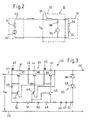
- FIG. 2 shows the connection of the coil 19 to the voltage source 25.
- the voltage source consists of the voltage generator 30 and the internal resistance 31. Their voltage can be changed to turn off the current from a high value to a low value.
- the voltage source 25 supplies the input voltage U e for a circuit 32, which contains a voltage-dependent resistor 33 as a series resistor, which forms a connected to the voltage source 25 series circuit with the coil 19.
- the coil 19 is composed of the inductor 34 and the series resistor 24.
- the coil 19 is connected in parallel with the series circuit of an auxiliary voltage source 35 and a rectifier diode 36.
- the rectifier diode 36 is inversely to the direction of the supplied from the voltage source 25th Poles current, ie it prevents that current flows through the auxiliary voltage source 35.
- FIG. 3 shows the circuit 32 with the voltage-dependent resistor 33.
- the circuit 32 includes one of the voltage source 25 to the coil 19 continuous negative line 26. At its input is the supplied from the voltage source input voltage U e .
- the positive terminal 27 is connected to the output terminal 40 via a plurality of cascaded transistors 37, 38, 39. Each of these transistors is bridged by a resistor 41, which is connected in series with a contact bridge 42.
- Each of the transistors 37, 38, 39 is controlled by an auxiliary transistor 43, 44, 45.
- the auxiliary transistor 45 is connected with its emitter to a reference path 46 of a plurality of Zener diodes 47, which is connected to the line 26.
- the reference path 46 defines the switching voltage U s , at which the transistors 37, 38, 39 are controlled in the blocking state.
- the reference path 46 is connected at one end to the line 26 and at the other end with a combination of a series resistor 48 with a diode 50 and a combination of a series resistor 51 with a diode 52nd
- the present at the positive terminal 27 input voltage U e passes through a resistor 53 and the resistors 51 and 48 and the diodes 52 and 50 to the reference path 46 which generates the reference voltage, which must be exceeded by the voltage U e to the auxiliary transistors 43rd To control 44 and 45 in the blocking state, whereby the transistors 37, 38 and 39 are also switched to the blocking state.
- the switching valve 18 During normal operation, in which the spool 10 is kept open, the switching valve 18 must remain closed. This means that the coil 19 is energized. This is achieved by the voltage source 25 generates the full input voltage U e . If this is present at the circuit 32, the transistors 37, 38, 39 are in the conductive state, so that the resistors 41 are bridged by the transistors. A current flows through the coil 19 to keep it activated.
- the voltage of the voltage source 25 is lowered. Thereafter, the transistors 37, 38, 39 are switched to the blocking state, so that the current from the current source now flows through the series-connected resistors 41.
- the high current through the coil 19 tries to continue to flow and discharges to the auxiliary voltage source 35, which is designed here as a Zener diode. This generates a current from its anode via the rectifier diode 36, the resistor 24 and the inductance 34. Since this distance is low impedance, there is a rapid discharge of the current of the coil 19, with the result that the switching valve 18 drops rapidly after a defined time.
- the switching valve thus has a defined and calculable shutdown time.
Landscapes
- Engineering & Computer Science (AREA)
- General Engineering & Computer Science (AREA)
- Mechanical Engineering (AREA)
- Magnetically Actuated Valves (AREA)
- Quick-Acting Or Multi-Walled Pipe Joints (AREA)
Description
- Die Erfindung betrifft ein schnell auslösendes Ventil, das eine von einer Spannungsquelle gespeiste Spule aufweist.
- Bei Schiebern zum Absperren von Rohrleitungen, welche Fluide führen, erfolgt die Betätigung in der Regel durch ein schnell auslösendes Schaltventil fluidisch, d.h. hydraulisch oder pneumatisch. Bei den Fluiden kann es sich um Gase, Flüssigkeiten, Feststoffe oder auch um Mehrphasensysteme handeln. Das Schaltventil ist in einer zu einem Aktuator des Schiebers führenden Fluidleitung vorhanden und wird elektrisch betätigt.
- Schiebersysteme benötigen häufig eine Schnellschluss-Funktion. Im Falle eines Stromausfalls oder einer anderweitigen Störung muss der Schieber unverzüglich in die Schließstellung gebracht werden. Bei einem fluidisch betätigten Schieber bedeutet dies, dass der Fluiddruck unverzüglich entlastet oder beaufschlagt werden muss.
- In sicherheitstechnischen Anwendungen, wie bei Explosions- oder Schnellschluss-Schiebern wird ein elektrisch angesteuertes Entlastungsventil mittels eines Stromes durch einen Elektromagneten geschlossen gehalten. Bei Fortfall des Stromes wird das Schaltventil zwangsweise durch Federn und/oder den anstehenden Druck des Mediums geöffnet. Somit ist sichergestellt, dass bei einem Stromausfall das Schaltventil öffnet, was wiederum zur Folge hat, dass der Schieber in den Sperrzustand bewegt wird. Das Schaltventil kann jedoch erst öffnen, wenn bei dem Elektromagneten, der es im Schließzustand gehalten hat; das Magnetfeld so weit abgebaut ist, dass die magnetische Haltekraft unter einen Grenzwert abgesunken ist. Die Zeit, in der die magnetische Flussdichte des Elektromagneten bzw. der Spulenstrom als Maß der magnetischen Feldstärke ausreichend abgebaut wird, bestimmt wesentlich die Öffnungszeit des Schaltventils. Die Richtlinien erfordern in bestimmten Fällen eine Schließzeit des Schiebers von 30 ms. Infolge der Induktivität der Spule des Schaltventils beträgt die Schließzeit in der Praxis bei einem gemessenen Fall 1,3 s.
- Der Oberbegriff des Patentanspruchs 1 geht aus von einem schnell auslösenden Ventil, das aus
DE 197 25 317 A1 bekannt ist. Das bekannte Ventil weist eine Steuereinheit auf, die das Anliegend von Gleichspannung detektiert und in Abhängigkeit davon wird ein Schaltmittel in Form eines Mosfet geschlossen. Parallel zu der Spule des gesteuerten Ventils liegt eine Hilfsspannungsquelle, die als spannungsabhängiger Widerstand bezeichnet ist. Die Steuerschaltung schaltet in Abhängigkeit von einer Abschalt-Induktionsspannung der Spule diese kurz. -
U.S. 5,345,119 beschreibt die Steuerung der Grenzfrequenz eines Filters mit variablen Widerständen und variablen Kondensatoren. Der variable Widerstand besteht aus einer Reihenschaltung mehrerer Einzelwiderstände, die jeweils durch einen elektronischen Schalter überbrückt werden können. - Der Erfindung liegt die Aufgabe zugrunde, ein schnell auslösendes Ventil zu schaffen, bei dem der spannungsabhängige Widerstand im Falle des Ausfalls eines von mehreren elektronischen Schaltern eine Abschaltung des Schaltventils bewirkt.
- Das schnell auslösende Ventil der vorliegenden Erfindung ist durch den Anspruch 1 definiert. Erfingdungsgemäß enthält der spannungsabhängige Widerstand mehrere kaskadenartig in Reihe geschaltete elektronische Schalter, die jeweils einen Serienwiderstand überbrücken und in den Sperrzustand gesteuert werden, wenn die anliegende Spannung eine vorgegebene Schaltspannung unterschreitet.
- Bei dem erfindungsgemäßen schnell auslösenden Ventil folgt keine Abschaltung des Erregerstroms, der die Spule des Schaltventils durchfließt, sondern eine Absenkung der Spannung der Spannungsquelle in Kombination mit einer entsprechenden Erhöhung des spannungsabhängigen Widerstandes. Der spannungsabhängige Widerstand hat unterhalb einer Schaltspannung Us einen hohen Widerstand und oberhalb von Us einen vernachlässigbar kleinen Widerstand. Parallel zu der Spule liegt eine Hilfsspannungsquelle, die vorzugsweise stromgesteuert ist und deren Spannung während des Ausschaltvorgangs dem Spulenstrom entgegenwirkt. Im Betriebszustand liegt eine so große Eingangsspannung an, dass der spannungsabhängige Widerstand niederohmig ist. Im Ausschaltvorgang unterschreitet die Eingangsspannung die Schaltspannung Us. Der spannungsabhängige Widerstand wird damit hochohmig. Der überwiegende Teil des Stroms wird nun über die Hilfsspannungsquelle geführt, so dass die Spule sich über die niederohmige Hilfsspannungsquelle schnell entladen kann. Damit sind die Spannungen und Zeiten zum Abschalten des Stromes vorhersehbar und berechenbar. Es ergeben sich somit definierte und kurze Öffnungszeiten des Sicherheitsventils.
- Nach der Erfindung ist vorgesehen, dass der spannungsabhängige Widerstand mehrere kaskadenartig in Reihe geschaltete elektronische Schalter enthält, die jeweils einen Serienwiderstand überbrücken und in den Sperrzustand gesteuert werden, wenn die anliegende Spannung eine vorgegebene Schaltspannung Us unterschreitet. Die Aufteilung in mehrere serielle elektronische Schalter hat den Vorteil, dass bei Ausfall mindestens eines elektronischen Schalters der spannungsabhängige Widerstand hoch wird, was zu einer Abschaltung des Schaltventils fuhrt. Die elektronischen Schaltern sind mit Steuerschaltern in der Weise verknüpft, dass sie dann, wenn die Eingangsspannung die Schaltspannung Us unterschreitet, in den Sperrzustand geschaltet werden. Die Höhe der Schaltspannung Us wird durch eine Referenzspannungsstrecke bestimmt, die mehrere Konstahtspannungselemente, z.B. Zenerdioden, enthält.
- Bei einer bevorzugten Aüsgestaltung der Erfindung ist vorgesehen, dass die Hilfsspannungsquelle aus mindestens einer Zenerdiode besteht. Die Zenerdiode ermöglicht einen schnellen und kontrollierten Abfluss des Spulenstroms, der über die Zenerdiode kurzgeschlossen wird und nicht über den spannungsabhängigen Widerstand fließen muss. Vorzugsweise ist die Zenerdiode mit einer Gleichrichterdiode in Reihe geschaltet, welche für den Stromfluss von der Spannungsquelle über die Zenerdiode undurchlässig ist und diesen somit sperrt. Die Gleichrichterdiode ist nur für den Entladestrom der Spule durchlässig.
- Im Folgenden wird ein Ausführungsbeispiel der Erfindung unter Bezugnahme auf die Zeichnungen näher erläutert. Diese Beschreibung eines detaillierten Ausführungsbeispiels ist nicht dahingehend zu verstehen, dass sie den Schutzbereich der Erfindung einschränkt. Dieser wird vielmehr durch die Ansprüche bestimmt.
- Es zeigen:
- Fig. 1
- eine schematische Darstellung eines gesamten Schiebersystems, einschließlich des Schiebers und des schnell ;auslösenden Ventils,
- Fig. 2
- ein schematisches Schaltbild der Steuerschaltung des Ventils, und
- Fig. 3
- eine detaillierte Darstellung des Bereichs III der Schaltung nach
Figur 2 . -
Figur 1 zeigt einen Schieber 10, der im Zuge einer Rohrleitung 11 angeordnet ist und eine bewegbare Schieberplatte 12 aufweist, welche den Rohrquerschnitt versperren kann. Der Schieber 10 weist einen Aktuator 13 auf, der bei dem vorliegenden Ausführungsbeispiel pneumatisch betätigt wird. Der Aktuator 13 besteht aus einem Zylinder, der einen Kolben 14 enthält. Der Schieber. 10 ist mit dem Kolben 14 verbunden. Der Kolben 14 steht unter der Wirkung einer Feder 15, die den Schieber in die Öffnungsstellung treibt. - Der Aktuator 13 ist mit einer Druckleitung 16 verbunden, die an eine Druckquelle 17 angeschlossen ist. Im Zuge der Druckleitung 16 ist das schnell auslösende Ventil 18 angeordnet, das im Öffnungsfall die Druckleitung 16 entlastet und den Druck aus ihr ablässt. Das Ventil 18 ist ein Schaltventil. Es enthält einen Elektromagneten mit einer Spule 19, in der ein ferromagnetisches Teil 20 angeordnet ist. Das Teil 20 ist mit einem Ventilteller 21 verbunden, welcher eine Öffnung 22 in der Druckleitung 16 verschließt, wenn die Spule 19 erregt ist und das Teil 20 hochzieht. Ist die Spule 19 aberregt, sinkt der Ventilteller 21 aufgrund der Schwerkraft oder durch eine Feder herab und gibt die Öffnung 22 frei. Die Spule 19 ist an eine steuerbare Spannungsquelle 25 angeschlossen. Diese liefert einen Strom, der durch die Spule 19 fließt und das Schaltventil 18 im Schließzustand hält. In diesem Zustand wird der Schieber 10 im Öffnungszustand gehalten. Im Falle eines Stromausfalls oder eines Ausfalls der Druckluft treibt die Feder 15 des Aktuators 13 den Schieber 10 in die Schließstellung.
-
Figur 2 zeigt den Anschluss der Spule 19 an die Spannungsquelle 25. Die Spannungsquelle besteht aus dem Spannungserzeuger 30 und dem Innenwiderstand 31. Ihre Spannung kann zum Abschalten des Stroms von einem hohen Wert auf einen niedrigen Wert verändert werden. - Die Spannungsquelle 25 liefert die Eingangsspannung Ue für eine Schaltung 32, die einen spannungsabhängigen Widerstand 33 als Reihenwiderstand enthält, welcher mit der Spule 19 eine an die Spannungsquelle 25 angeschlossene Reihenschaltung bildet. Die Spule 19 besteht aus der Induktivität 34 und dem Reihenwiderstand 24. Der Spule 19 parallel geschaltet ist die Reihenschaltung aus einer Hilfsspannungsquelle 35 und einer Gleichrichterdiode 36. Die Gleichrichterdiode 36 ist invers zu der Richtung des von der Spannungsquelle 25 gelieferten Stromes gepolt, d.h. sie verhindert, dass dieser Strom über die Hilfsspannungsquelle 35 fließt.
-
Figur 3 zeigt die Schaltung 32 mit dem spannungsabhängigen Widerstand 33. Die Schaltung 32 enthält eine von der Spannungsquelle 25 zur Spule 19 durchgehende Minusleitung 26. An ihrem Eingang steht die von der Spannungsquelle gelieferte Eingangsspannung Ue. Der Pluspol 27 ist über mehrere kaskadenartig in Reihe geschaltete Transistoren 37, 38, 39 mit dem Ausgangspol 40 verbunden. Jeder dieser Transistoren ist durch einen Widerstand 41 überbrückt, der in Reihe mit einer Kontaktbrücke 42 geschaltet ist. Jeder der Transistoren 37, 38, 39 wird von einem Hilfstransistor 43, 44, 45 gesteuert. Der Hilfstransistor 45 ist mit seinem Emitter an eine Referenzstrecke 46 aus mehreren Zenerdioden 47 angeschlossen, welche mit der Leitung 26 verbunden ist. Die Referenzstrecke 46 definiert die Schaltspannung Us, bei der die Transistoren 37, 38, 39 in den Sperrzustand gesteuert werden. - Die Referenzstrecke 46 ist an einem Ende mit der Leitung 26 verbunden und am anderen Ende mit jeweils einer Kombination eines Reihenwiderstandes 48 mit einer Diode 50 bzw. einer Kombination eines Reihenwiderstandes 51 mit einer Diode 52.
- Die an dem Pluspol 27 anstehende Eingangsspannung Ue gelangt über einen Widerstand 53 sowie die Widerstände 51 und 48 und die Dioden 52 und 50 an die Referenzstrecke 46, die die Referenzspannung erzeugt, die von der Spannung Ue unterschritten werden muss, um die Hilfstransistoren 43, 44 und 45 in den Sperrzustand zu steuern, wodurch die Transistoren 37, 38 und 39 ebenfalls in den Sperrzustand geschaltet werden.
- Während des normalen Betriebs, in dem der Schieber 10 geöffnet gehalten wird, muss das Schaltventil 18 geschlossen bleiben. Dies bedeutet, dass die Spule 19 erregt wird. Dies wird erreicht, indem die Spannungsquelle 25 die volle Eingangsspannung Ue erzeugt. Wenn diese an der Schaltung 32 ansteht, sind die Transistoren 37, 38, 39 im leitenden Zustand, so dass die Widerstände 41 von den Transistoren überbrückt werden. Es fließt ein Strom durch die Spule 19, um diese aktiviert zu halten.
- Im Falle eines erforderlichen Schnellschlusses des Schiebers 10 wird die Spannung der Spannungsquelle 25 abgesenkt. Daraufhin werden die Transistoren 37, 38, 39 in den Sperrzustand geschaltet, so dass der Strom von der Stromquelle aus nun über die in Reihe geschalteten Widerstände 41 fließt. Der hohe Strom durch die Spule 19 versucht weiter zu fließen und entlädt sich zu der Hilfsspannungsquelle 35, die hier als Zenerdiode ausgebildet ist. Diese erzeugt einen Strom von ihrer Anode über die Gleichrichterdiode 36, den Widerstand 24 und die Induktivität 34. Da diese Strecke niederohmig ist, erfolgt eine schnelle Entladung des Stromes der Spule 19 mit der Folge, dass das Schaltventil 18 nach einer definierten Zeit schnell abfällt. Das Schaltventil hat somit eine definierte und berechenbare Abschaltzeit.
Claims (5)
- Schnell auslösendes Ventil (18), das eine von einer Spannungsquelle (25) gespeiste Spule (19) aufweist,
wobei zwischen der Spannungsquelle (25) und der Spule (19) ein spannungsabhängiger Widerstand (33) vorgesehen ist und der Spule (19) eine Hilfsspannungsquelle (35) parallel geschaltet ist, deren Spannung derjenigen der Spannungsquelle (25) entgegengerichtet ist,
dadurch gekennzeichnet,
dass der spannungsabhängige Widerstand (33) mehrere kaskadenartig in Reihe geschaltete elektronische Schalter (37, 38, 39) enthält, die jeweils einen Serienwiderstand (41) überbrücken und in den Sperrzustand gesteuert werden, wenn die anliegende Spannung (Ue) eine vorgegebene Schaltspannung (Us) unterschreitet. - Schnell auslösendes Ventil nach Anspruch 1, dadurch gekennzeichnet, dass die Hilfsspannungsquelle (35) aus mindestens einer Zenerdiode besteht.
- Schnell auslösendes Ventil nach Anspruch 1 oder 2, dadurch gekennzeichnet, dass die Hilfsspannungsquelle (35) in Reihe mit einer Gleichrichterdiode (36) parallel zu der Spule (19) geschaltet ist.
- Schnell auslösendes Ventil nach Anspruch 3, dadurch gekennzeichnet, dass die Schaltspannung (Us) durch eine Referenzspannungsstrecke (46) bestimmt wird.
- Schnell auslösendes Ventil nach Anspruch 3 oder 4, dadurch gekennzeichnet, dass jeder der elektronischen Schalter (37, 38, 39) durch einen Hilfstransistor (43, 44, 45) geschaltet wird.
Applications Claiming Priority (2)
| Application Number | Priority Date | Filing Date | Title |
|---|---|---|---|
| DE202004004156U DE202004004156U1 (de) | 2004-03-17 | 2004-03-17 | Schnell auslösendes Ventil |
| PCT/EP2005/002661 WO2005093764A1 (de) | 2004-03-17 | 2005-03-12 | Schnell auslösendes ventil |
Publications (2)
| Publication Number | Publication Date |
|---|---|
| EP1726020A1 EP1726020A1 (de) | 2006-11-29 |
| EP1726020B1 true EP1726020B1 (de) | 2010-05-05 |
Family
ID=34833328
Family Applications (1)
| Application Number | Title | Priority Date | Filing Date |
|---|---|---|---|
| EP05716011A Expired - Lifetime EP1726020B1 (de) | 2004-03-17 | 2005-03-12 | Schnell auslösendes ventil |
Country Status (8)
| Country | Link |
|---|---|
| US (1) | US8023243B2 (de) |
| EP (1) | EP1726020B1 (de) |
| AT (1) | ATE467218T1 (de) |
| AU (1) | AU2005226084B2 (de) |
| CA (1) | CA2558127C (de) |
| DE (2) | DE202004004156U1 (de) |
| DK (1) | DK1726020T3 (de) |
| WO (1) | WO2005093764A1 (de) |
Families Citing this family (5)
| Publication number | Priority date | Publication date | Assignee | Title |
|---|---|---|---|---|
| US8172197B2 (en) | 2006-07-06 | 2012-05-08 | Mks Instruments, Inc. | Fast-acting pneumatic diaphragm valve |
| DE102007006458A1 (de) * | 2007-02-05 | 2008-08-07 | Sms Demag Ag | Stranggießeinrichtung zum Erzeugen von Brammen aus Stahl |
| US10236108B2 (en) | 2016-08-16 | 2019-03-19 | Target Rock Division Of Curtiss-Wright Flow Control Corporation | Solenoid coil discharging circuit |
| US11873914B2 (en) * | 2022-04-27 | 2024-01-16 | Bueno Technology Co., Ltd. | Buffer valve |
| US11835142B2 (en) * | 2022-04-27 | 2023-12-05 | Bueno Technology Co., Ltd. | Buffer valve |
Family Cites Families (11)
| Publication number | Priority date | Publication date | Assignee | Title |
|---|---|---|---|---|
| US3397322A (en) * | 1965-01-25 | 1968-08-13 | Raymond P. Wolgast | Portable resistance spot welder |
| CH586483A5 (de) | 1975-01-16 | 1977-03-31 | Bbc Brown Boveri & Cie | |
| EP0006843B2 (de) * | 1978-07-06 | 1987-09-23 | Bürkert GmbH | Magnetventil mit elektronischer Steuerung |
| US4649458A (en) * | 1984-03-09 | 1987-03-10 | Ogura Clutch | Control circuits for electromagnetic coupling apparatus |
| KR860007688A (ko) * | 1985-03-08 | 1986-10-15 | 시끼 모리야 | 전자석장치(電磁石裝置) |
| US4705322A (en) * | 1985-07-05 | 1987-11-10 | American Telephone And Telegraph Company, At&T Bell Laboratories | Protection of inductive load switching transistors from inductive surge created overvoltage conditions |
| JPH0528727Y2 (de) * | 1988-03-31 | 1993-07-23 | ||
| US5164872A (en) * | 1991-06-17 | 1992-11-17 | General Electric Company | Load circuit commutation circuit |
| US5345119A (en) * | 1992-09-16 | 1994-09-06 | At&T Bell Laboratories | Continuous-time filter tuning with a delay-locked-loop in mass storage systems or the like |
| DE19725317B4 (de) | 1997-06-09 | 2005-06-23 | Vickers Systems Zweigniederlassung Der Trinova Gmbh | Schaltungsanordnung zur Ansteuerung eines mit Gleichspannung betätigbaren Magnetventiles |
| US6687553B2 (en) * | 2000-06-29 | 2004-02-03 | Borgwarner Inc. | Dual gain variable control system |
-
2004
- 2004-03-17 DE DE202004004156U patent/DE202004004156U1/de not_active Expired - Lifetime
-
2005
- 2005-03-12 EP EP05716011A patent/EP1726020B1/de not_active Expired - Lifetime
- 2005-03-12 AT AT05716011T patent/ATE467218T1/de active
- 2005-03-12 CA CA2558127A patent/CA2558127C/en not_active Expired - Fee Related
- 2005-03-12 DK DK05716011.1T patent/DK1726020T3/da active
- 2005-03-12 US US10/598,963 patent/US8023243B2/en not_active Expired - Fee Related
- 2005-03-12 AU AU2005226084A patent/AU2005226084B2/en not_active Ceased
- 2005-03-12 WO PCT/EP2005/002661 patent/WO2005093764A1/de not_active Ceased
- 2005-03-12 DE DE502005009524T patent/DE502005009524D1/de not_active Expired - Lifetime
Also Published As
| Publication number | Publication date |
|---|---|
| AU2005226084A1 (en) | 2005-10-06 |
| AU2005226084B2 (en) | 2010-07-22 |
| ATE467218T1 (de) | 2010-05-15 |
| US20070097590A1 (en) | 2007-05-03 |
| DE202004004156U1 (de) | 2005-08-04 |
| DE502005009524D1 (de) | 2010-06-17 |
| US8023243B2 (en) | 2011-09-20 |
| EP1726020A1 (de) | 2006-11-29 |
| DK1726020T3 (da) | 2010-08-09 |
| WO2005093764A1 (de) | 2005-10-06 |
| CA2558127C (en) | 2013-07-09 |
| CA2558127A1 (en) | 2005-10-06 |
Similar Documents
| Publication | Publication Date | Title |
|---|---|---|
| DE102014219634A1 (de) | Druckreduzierventil mit gesonderten Radialbohrungen für unterschiedliche Fluidströmungspfade | |
| DE10325363A1 (de) | Sicherheitsschaltgerät zum fehlersicheren Abschalten eines elektrischen Verbrauchers sowie entsprechendes Verfahren | |
| DE102011104530A1 (de) | Hydraulische Stellanordnung | |
| WO2016134909A1 (de) | Ventil zum schalten von fluiden, loeschanlage und verfahren | |
| EP2172656A1 (de) | Hydraulische Auslöseeinheit für eine Ventileinheit in einer Kraftmaschinenanlage, insbesondere für ein Schnellschlussventil einer Turbinenanlage | |
| EP1630425A2 (de) | Sicherheitsschaltung für medienbetriebene Verbraucher und Verfahren zum Betrieb derselben | |
| EP0433791A1 (de) | Antrieb für ein Speiseventil | |
| EP2597317B1 (de) | Motorpumpenaggregat für eine Werkzeugmaschine | |
| EP2236452B1 (de) | Hubmodul | |
| EP1726020A1 (de) | Schnell auslösendes ventil | |
| DE102012011062A1 (de) | Hydrauliksystem und Druckbegrenzungsventil | |
| DE102008023198A1 (de) | Hydraulikventilsteuergerät und Verfahren zum Überprüfen eines Hydraulikventilsteuergeräts | |
| EP2711595A1 (de) | Ventilvorrichtung mit Doppelsitz | |
| EP2767719A2 (de) | Ventil | |
| EP0988482B1 (de) | Elektromagnetischer stellantrieb | |
| DE102008061238A1 (de) | Vorrichtung für einen hydraulischen Antrieb für eine elektrische Schaltanlage | |
| DE102007062665A1 (de) | Magnetbetätigte Ventilanordnung und Betätigungsmagnet | |
| DE626254C (de) | Einrichtung zur Verstellung eines in einer Durchflussoeffnung, beispielsweisen in einer Rohrleitung, angebrachten beweglichen Verstellorgans in Abhaengigkeit von der Stroungsmenge | |
| DE2835063A1 (de) | Hydraulischer antrieb | |
| DE2509033A1 (de) | Sicherheitsventil | |
| DE3007787C2 (de) | ||
| DE102011012305A1 (de) | Hydraulische Stellanordnung | |
| DE102022112275A1 (de) | Vorsteuerbares hydraulisches Sitzventil und Anordnung zur Spülung eines hydraulischen Ventils | |
| DE102018124864A1 (de) | Hochdruck-Sicherheitsventil | |
| CH646297A5 (de) | Vorrichtung zur steuerung der elektroden eines lichtbogenofens. |
Legal Events
| Date | Code | Title | Description |
|---|---|---|---|
| PUAI | Public reference made under article 153(3) epc to a published international application that has entered the european phase |
Free format text: ORIGINAL CODE: 0009012 |
|
| 17P | Request for examination filed |
Effective date: 20060823 |
|
| AK | Designated contracting states |
Kind code of ref document: A1 Designated state(s): AT BE BG CH CY CZ DE DK EE ES FI FR GB GR HU IE IS IT LI LT LU MC NL PL PT RO SE SI SK TR |
|
| DAX | Request for extension of the european patent (deleted) | ||
| 17Q | First examination report despatched |
Effective date: 20070911 |
|
| GRAP | Despatch of communication of intention to grant a patent |
Free format text: ORIGINAL CODE: EPIDOSNIGR1 |
|
| GRAS | Grant fee paid |
Free format text: ORIGINAL CODE: EPIDOSNIGR3 |
|
| RIN1 | Information on inventor provided before grant (corrected) |
Inventor name: KAMMERER, BERND Inventor name: ADAMS, HANS |
|
| GRAA | (expected) grant |
Free format text: ORIGINAL CODE: 0009210 |
|
| AK | Designated contracting states |
Kind code of ref document: B1 Designated state(s): AT BE BG CH CY CZ DE DK EE ES FI FR GB GR HU IE IS IT LI LT LU MC NL PL PT RO SE SI SK TR |
|
| REG | Reference to a national code |
Ref country code: GB Ref legal event code: FG4D Free format text: NOT ENGLISH |
|
| REG | Reference to a national code |
Ref country code: CH Ref legal event code: EP |
|
| REG | Reference to a national code |
Ref country code: IE Ref legal event code: FG4D Free format text: LANGUAGE OF EP DOCUMENT: GERMAN |
|
| REF | Corresponds to: |
Ref document number: 502005009524 Country of ref document: DE Date of ref document: 20100617 Kind code of ref document: P |
|
| REG | Reference to a national code |
Ref country code: CH Ref legal event code: NV Representative=s name: ISLER & PEDRAZZINI AG |
|
| REG | Reference to a national code |
Ref country code: NL Ref legal event code: T3 |
|
| REG | Reference to a national code |
Ref country code: DK Ref legal event code: T3 |
|
| REG | Reference to a national code |
Ref country code: SE Ref legal event code: TRGR |
|
| LTIE | Lt: invalidation of european patent or patent extension |
Effective date: 20100505 |
|
| PG25 | Lapsed in a contracting state [announced via postgrant information from national office to epo] |
Ref country code: LT Free format text: LAPSE BECAUSE OF FAILURE TO SUBMIT A TRANSLATION OF THE DESCRIPTION OR TO PAY THE FEE WITHIN THE PRESCRIBED TIME-LIMIT Effective date: 20100505 Ref country code: ES Free format text: LAPSE BECAUSE OF FAILURE TO SUBMIT A TRANSLATION OF THE DESCRIPTION OR TO PAY THE FEE WITHIN THE PRESCRIBED TIME-LIMIT Effective date: 20100816 |
|
| PG25 | Lapsed in a contracting state [announced via postgrant information from national office to epo] |
Ref country code: IS Free format text: LAPSE BECAUSE OF FAILURE TO SUBMIT A TRANSLATION OF THE DESCRIPTION OR TO PAY THE FEE WITHIN THE PRESCRIBED TIME-LIMIT Effective date: 20100905 Ref country code: SI Free format text: LAPSE BECAUSE OF FAILURE TO SUBMIT A TRANSLATION OF THE DESCRIPTION OR TO PAY THE FEE WITHIN THE PRESCRIBED TIME-LIMIT Effective date: 20100505 Ref country code: FI Free format text: LAPSE BECAUSE OF FAILURE TO SUBMIT A TRANSLATION OF THE DESCRIPTION OR TO PAY THE FEE WITHIN THE PRESCRIBED TIME-LIMIT Effective date: 20100505 |
|
| PG25 | Lapsed in a contracting state [announced via postgrant information from national office to epo] |
Ref country code: PL Free format text: LAPSE BECAUSE OF FAILURE TO SUBMIT A TRANSLATION OF THE DESCRIPTION OR TO PAY THE FEE WITHIN THE PRESCRIBED TIME-LIMIT Effective date: 20100505 Ref country code: GR Free format text: LAPSE BECAUSE OF FAILURE TO SUBMIT A TRANSLATION OF THE DESCRIPTION OR TO PAY THE FEE WITHIN THE PRESCRIBED TIME-LIMIT Effective date: 20100806 Ref country code: CY Free format text: LAPSE BECAUSE OF FAILURE TO SUBMIT A TRANSLATION OF THE DESCRIPTION OR TO PAY THE FEE WITHIN THE PRESCRIBED TIME-LIMIT Effective date: 20100505 |
|
| PG25 | Lapsed in a contracting state [announced via postgrant information from national office to epo] |
Ref country code: PT Free format text: LAPSE BECAUSE OF FAILURE TO SUBMIT A TRANSLATION OF THE DESCRIPTION OR TO PAY THE FEE WITHIN THE PRESCRIBED TIME-LIMIT Effective date: 20100906 Ref country code: EE Free format text: LAPSE BECAUSE OF FAILURE TO SUBMIT A TRANSLATION OF THE DESCRIPTION OR TO PAY THE FEE WITHIN THE PRESCRIBED TIME-LIMIT Effective date: 20100505 |
|
| PG25 | Lapsed in a contracting state [announced via postgrant information from national office to epo] |
Ref country code: SK Free format text: LAPSE BECAUSE OF FAILURE TO SUBMIT A TRANSLATION OF THE DESCRIPTION OR TO PAY THE FEE WITHIN THE PRESCRIBED TIME-LIMIT Effective date: 20100505 Ref country code: RO Free format text: LAPSE BECAUSE OF FAILURE TO SUBMIT A TRANSLATION OF THE DESCRIPTION OR TO PAY THE FEE WITHIN THE PRESCRIBED TIME-LIMIT Effective date: 20100505 |
|
| PLBE | No opposition filed within time limit |
Free format text: ORIGINAL CODE: 0009261 |
|
| STAA | Information on the status of an ep patent application or granted ep patent |
Free format text: STATUS: NO OPPOSITION FILED WITHIN TIME LIMIT |
|
| 26N | No opposition filed |
Effective date: 20110208 |
|
| REG | Reference to a national code |
Ref country code: DE Ref legal event code: R097 Ref document number: 502005009524 Country of ref document: DE Effective date: 20110207 |
|
| BERE | Be: lapsed |
Owner name: ERBEN KAMMERER K.G. Effective date: 20110331 |
|
| PG25 | Lapsed in a contracting state [announced via postgrant information from national office to epo] |
Ref country code: MC Free format text: LAPSE BECAUSE OF NON-PAYMENT OF DUE FEES Effective date: 20110331 |
|
| PG25 | Lapsed in a contracting state [announced via postgrant information from national office to epo] |
Ref country code: BE Free format text: LAPSE BECAUSE OF NON-PAYMENT OF DUE FEES Effective date: 20110331 |
|
| PG25 | Lapsed in a contracting state [announced via postgrant information from national office to epo] |
Ref country code: LU Free format text: LAPSE BECAUSE OF NON-PAYMENT OF DUE FEES Effective date: 20110312 |
|
| PG25 | Lapsed in a contracting state [announced via postgrant information from national office to epo] |
Ref country code: BG Free format text: LAPSE BECAUSE OF FAILURE TO SUBMIT A TRANSLATION OF THE DESCRIPTION OR TO PAY THE FEE WITHIN THE PRESCRIBED TIME-LIMIT Effective date: 20100805 Ref country code: TR Free format text: LAPSE BECAUSE OF FAILURE TO SUBMIT A TRANSLATION OF THE DESCRIPTION OR TO PAY THE FEE WITHIN THE PRESCRIBED TIME-LIMIT Effective date: 20100505 |
|
| PG25 | Lapsed in a contracting state [announced via postgrant information from national office to epo] |
Ref country code: HU Free format text: LAPSE BECAUSE OF FAILURE TO SUBMIT A TRANSLATION OF THE DESCRIPTION OR TO PAY THE FEE WITHIN THE PRESCRIBED TIME-LIMIT Effective date: 20100505 |
|
| PGFP | Annual fee paid to national office [announced via postgrant information from national office to epo] |
Ref country code: CZ Payment date: 20130911 Year of fee payment: 9 |
|
| REG | Reference to a national code |
Ref country code: DE Ref legal event code: R119 Ref document number: 502005009524 Country of ref document: DE |
|
| PG25 | Lapsed in a contracting state [announced via postgrant information from national office to epo] |
Ref country code: CZ Free format text: LAPSE BECAUSE OF NON-PAYMENT OF DUE FEES Effective date: 20140312 |
|
| PGFP | Annual fee paid to national office [announced via postgrant information from national office to epo] |
Ref country code: CH Payment date: 20140922 Year of fee payment: 10 Ref country code: DK Payment date: 20140924 Year of fee payment: 10 Ref country code: IE Payment date: 20140924 Year of fee payment: 10 |
|
| PGFP | Annual fee paid to national office [announced via postgrant information from national office to epo] |
Ref country code: GB Payment date: 20140923 Year of fee payment: 10 Ref country code: AT Payment date: 20140922 Year of fee payment: 10 Ref country code: SE Payment date: 20140923 Year of fee payment: 10 |
|
| REG | Reference to a national code |
Ref country code: DE Ref legal event code: R073 Ref document number: 502005009524 Country of ref document: DE |
|
| PGFP | Annual fee paid to national office [announced via postgrant information from national office to epo] |
Ref country code: IT Payment date: 20140923 Year of fee payment: 10 |
|
| REG | Reference to a national code |
Ref country code: DE Ref legal event code: R119 Ref document number: 502005009524 Country of ref document: DE Effective date: 20141001 |
|
| REG | Reference to a national code |
Ref country code: DE Ref legal event code: R074 Ref document number: 502005009524 Country of ref document: DE |
|
| PG25 | Lapsed in a contracting state [announced via postgrant information from national office to epo] |
Ref country code: DE Free format text: LAPSE BECAUSE OF NON-PAYMENT OF DUE FEES Effective date: 20141001 |
|
| PGFP | Annual fee paid to national office [announced via postgrant information from national office to epo] |
Ref country code: FR Payment date: 20140917 Year of fee payment: 10 |
|
| PGFP | Annual fee paid to national office [announced via postgrant information from national office to epo] |
Ref country code: NL Payment date: 20140922 Year of fee payment: 10 |
|
| REG | Reference to a national code |
Ref country code: DE Ref legal event code: R074 Ref document number: 502005009524 Country of ref document: DE Effective date: 20150129 |
|
| PGFP | Annual fee paid to national office [announced via postgrant information from national office to epo] |
Ref country code: DE Payment date: 20141128 Year of fee payment: 10 |
|
| PGRI | Patent reinstated in contracting state [announced from national office to epo] |
Ref country code: DE Effective date: 20150126 |
|
| REG | Reference to a national code |
Ref country code: DE Ref legal event code: R119 Ref document number: 502005009524 Country of ref document: DE |
|
| REG | Reference to a national code |
Ref country code: DK Ref legal event code: EBP Effective date: 20150331 |
|
| REG | Reference to a national code |
Ref country code: CH Ref legal event code: PL |
|
| REG | Reference to a national code |
Ref country code: AT Ref legal event code: MM01 Ref document number: 467218 Country of ref document: AT Kind code of ref document: T Effective date: 20150312 |
|
| GBPC | Gb: european patent ceased through non-payment of renewal fee |
Effective date: 20150312 |
|
| PG25 | Lapsed in a contracting state [announced via postgrant information from national office to epo] |
Ref country code: SE Free format text: LAPSE BECAUSE OF NON-PAYMENT OF DUE FEES Effective date: 20150313 |
|
| REG | Reference to a national code |
Ref country code: SE Ref legal event code: EUG |
|
| REG | Reference to a national code |
Ref country code: NL Ref legal event code: MM Effective date: 20150401 |
|
| PG25 | Lapsed in a contracting state [announced via postgrant information from national office to epo] |
Ref country code: IT Free format text: LAPSE BECAUSE OF NON-PAYMENT OF DUE FEES Effective date: 20150312 |
|
| REG | Reference to a national code |
Ref country code: FR Ref legal event code: ST Effective date: 20151130 |
|
| REG | Reference to a national code |
Ref country code: IE Ref legal event code: MM4A |
|
| PG25 | Lapsed in a contracting state [announced via postgrant information from national office to epo] |
Ref country code: GB Free format text: LAPSE BECAUSE OF NON-PAYMENT OF DUE FEES Effective date: 20150312 Ref country code: LI Free format text: LAPSE BECAUSE OF NON-PAYMENT OF DUE FEES Effective date: 20150331 Ref country code: IE Free format text: LAPSE BECAUSE OF NON-PAYMENT OF DUE FEES Effective date: 20150312 Ref country code: CH Free format text: LAPSE BECAUSE OF NON-PAYMENT OF DUE FEES Effective date: 20150331 |
|
| PG25 | Lapsed in a contracting state [announced via postgrant information from national office to epo] |
Ref country code: AT Free format text: LAPSE BECAUSE OF NON-PAYMENT OF DUE FEES Effective date: 20150312 Ref country code: FR Free format text: LAPSE BECAUSE OF NON-PAYMENT OF DUE FEES Effective date: 20150331 |
|
| PG25 | Lapsed in a contracting state [announced via postgrant information from national office to epo] |
Ref country code: DK Free format text: LAPSE BECAUSE OF NON-PAYMENT OF DUE FEES Effective date: 20150331 |
|
| PG25 | Lapsed in a contracting state [announced via postgrant information from national office to epo] |
Ref country code: DE Free format text: LAPSE BECAUSE OF NON-PAYMENT OF DUE FEES Effective date: 20151001 |
|
| PG25 | Lapsed in a contracting state [announced via postgrant information from national office to epo] |
Ref country code: NL Free format text: LAPSE BECAUSE OF NON-PAYMENT OF DUE FEES Effective date: 20150401 |