EP1725864B1 - Photometric analysis - Google Patents
Photometric analysis Download PDFInfo
- Publication number
- EP1725864B1 EP1725864B1 EP05799710A EP05799710A EP1725864B1 EP 1725864 B1 EP1725864 B1 EP 1725864B1 EP 05799710 A EP05799710 A EP 05799710A EP 05799710 A EP05799710 A EP 05799710A EP 1725864 B1 EP1725864 B1 EP 1725864B1
- Authority
- EP
- European Patent Office
- Prior art keywords
- photometric
- cell
- instrument
- analysis
- sample
- Prior art date
- Legal status (The legal status is an assumption and is not a legal conclusion. Google has not performed a legal analysis and makes no representation as to the accuracy of the status listed.)
- Active
Links
- 238000005375 photometry Methods 0.000 title claims description 25
- 238000004458 analytical method Methods 0.000 claims description 130
- 238000012384 transportation and delivery Methods 0.000 claims description 130
- 239000003795 chemical substances by application Substances 0.000 claims description 109
- XLYOFNOQVPJJNP-UHFFFAOYSA-N water Substances O XLYOFNOQVPJJNP-UHFFFAOYSA-N 0.000 claims description 103
- 239000003153 chemical reaction reagent Substances 0.000 claims description 93
- 230000003287 optical effect Effects 0.000 claims description 74
- ZAMOUSCENKQFHK-UHFFFAOYSA-N Chlorine atom Chemical compound [Cl] ZAMOUSCENKQFHK-UHFFFAOYSA-N 0.000 claims description 71
- 239000000460 chlorine Substances 0.000 claims description 71
- 229910052801 chlorine Inorganic materials 0.000 claims description 71
- 239000007788 liquid Substances 0.000 claims description 61
- 238000000034 method Methods 0.000 claims description 40
- 238000002156 mixing Methods 0.000 claims description 28
- 239000012491 analyte Substances 0.000 claims description 16
- 230000009471 action Effects 0.000 claims description 15
- 239000011159 matrix material Substances 0.000 claims description 15
- 150000003839 salts Chemical class 0.000 claims description 11
- 230000002093 peripheral effect Effects 0.000 claims description 9
- 239000008363 phosphate buffer Substances 0.000 claims description 6
- 230000004888 barrier function Effects 0.000 claims description 5
- 239000000872 buffer Substances 0.000 claims description 5
- 239000007853 buffer solution Substances 0.000 claims description 5
- XMBWDFGMSWQBCA-UHFFFAOYSA-M iodide Chemical compound [I-] XMBWDFGMSWQBCA-UHFFFAOYSA-M 0.000 claims description 5
- 239000007795 chemical reaction product Substances 0.000 claims description 4
- 239000000243 solution Substances 0.000 description 37
- 239000011521 glass Substances 0.000 description 30
- XFXPMWWXUTWYJX-UHFFFAOYSA-N Cyanide Chemical compound N#[C-] XFXPMWWXUTWYJX-UHFFFAOYSA-N 0.000 description 24
- 239000004033 plastic Substances 0.000 description 21
- 239000000969 carrier Substances 0.000 description 20
- 230000033001 locomotion Effects 0.000 description 20
- 238000006243 chemical reaction Methods 0.000 description 17
- 238000005516 engineering process Methods 0.000 description 16
- 238000003825 pressing Methods 0.000 description 16
- OKKJLVBELUTLKV-UHFFFAOYSA-N Methanol Chemical compound OC OKKJLVBELUTLKV-UHFFFAOYSA-N 0.000 description 15
- 238000011068 loading method Methods 0.000 description 15
- 238000012360 testing method Methods 0.000 description 15
- -1 molybdate ions Chemical class 0.000 description 14
- 230000009286 beneficial effect Effects 0.000 description 13
- 239000008367 deionised water Substances 0.000 description 12
- 229910021641 deionized water Inorganic materials 0.000 description 12
- QAOWNCQODCNURD-UHFFFAOYSA-L Sulfate Chemical compound [O-]S([O-])(=O)=O QAOWNCQODCNURD-UHFFFAOYSA-L 0.000 description 11
- 238000005470 impregnation Methods 0.000 description 11
- 238000003432 Konig synthesis reaction Methods 0.000 description 10
- 239000010949 copper Substances 0.000 description 10
- 238000011161 development Methods 0.000 description 10
- JMANVNJQNLATNU-UHFFFAOYSA-N glycolonitrile Natural products N#CC#N JMANVNJQNLATNU-UHFFFAOYSA-N 0.000 description 10
- RYGMFSIKBFXOCR-UHFFFAOYSA-N Copper Chemical compound [Cu] RYGMFSIKBFXOCR-UHFFFAOYSA-N 0.000 description 9
- HEMHJVSKTPXQMS-UHFFFAOYSA-M Sodium hydroxide Chemical compound [OH-].[Na+] HEMHJVSKTPXQMS-UHFFFAOYSA-M 0.000 description 9
- GDTBXPJZTBHREO-UHFFFAOYSA-N bromine Substances BrBr GDTBXPJZTBHREO-UHFFFAOYSA-N 0.000 description 9
- 229910052802 copper Inorganic materials 0.000 description 9
- WKBOTKDWSSQWDR-UHFFFAOYSA-N Bromine atom Chemical compound [Br] WKBOTKDWSSQWDR-UHFFFAOYSA-N 0.000 description 8
- 229910052794 bromium Inorganic materials 0.000 description 8
- XBDQKXXYIPTUBI-UHFFFAOYSA-N dimethylselenoniopropionate Natural products CCC(O)=O XBDQKXXYIPTUBI-UHFFFAOYSA-N 0.000 description 8
- 238000012986 modification Methods 0.000 description 8
- 230000004048 modification Effects 0.000 description 8
- 235000020188 drinking water Nutrition 0.000 description 7
- 239000003651 drinking water Substances 0.000 description 7
- 239000000463 material Substances 0.000 description 7
- QGZKDVFQNNGYKY-UHFFFAOYSA-N Ammonia Chemical compound N QGZKDVFQNNGYKY-UHFFFAOYSA-N 0.000 description 6
- 229910019142 PO4 Inorganic materials 0.000 description 6
- 239000000853 adhesive Substances 0.000 description 6
- 230000001070 adhesive effect Effects 0.000 description 6
- 238000007654 immersion Methods 0.000 description 6
- NBIIXXVUZAFLBC-UHFFFAOYSA-K phosphate Chemical compound [O-]P([O-])([O-])=O NBIIXXVUZAFLBC-UHFFFAOYSA-K 0.000 description 6
- 235000021317 phosphate Nutrition 0.000 description 6
- NLKNQRATVPKPDG-UHFFFAOYSA-M potassium iodide Chemical compound [K+].[I-] NLKNQRATVPKPDG-UHFFFAOYSA-M 0.000 description 6
- 239000008399 tap water Substances 0.000 description 6
- 235000020679 tap water Nutrition 0.000 description 6
- 230000002378 acidificating effect Effects 0.000 description 5
- 239000011575 calcium Substances 0.000 description 5
- 229910052791 calcium Inorganic materials 0.000 description 5
- QPJDMGCKMHUXFD-UHFFFAOYSA-N cyanogen chloride Chemical compound ClC#N QPJDMGCKMHUXFD-UHFFFAOYSA-N 0.000 description 5
- 230000002140 halogenating effect Effects 0.000 description 5
- 238000003780 insertion Methods 0.000 description 5
- 239000007787 solid Substances 0.000 description 5
- PTBDIHRZYDMNKB-UHFFFAOYSA-N 2,2-Bis(hydroxymethyl)propionic acid Chemical compound OCC(C)(CO)C(O)=O PTBDIHRZYDMNKB-UHFFFAOYSA-N 0.000 description 4
- OYPRJOBELJOOCE-UHFFFAOYSA-N Calcium Chemical compound [Ca] OYPRJOBELJOOCE-UHFFFAOYSA-N 0.000 description 4
- 230000008901 benefit Effects 0.000 description 4
- 230000037431 insertion Effects 0.000 description 4
- 230000002452 interceptive effect Effects 0.000 description 4
- ZFSLODLOARCGLH-UHFFFAOYSA-N isocyanuric acid Chemical compound OC1=NC(O)=NC(O)=N1 ZFSLODLOARCGLH-UHFFFAOYSA-N 0.000 description 4
- 239000010452 phosphate Substances 0.000 description 4
- 235000019260 propionic acid Nutrition 0.000 description 4
- JUJWROOIHBZHMG-UHFFFAOYSA-N pyridine Substances C1=CC=NC=C1 JUJWROOIHBZHMG-UHFFFAOYSA-N 0.000 description 4
- IUVKMZGDUIUOCP-BTNSXGMBSA-N quinbolone Chemical compound O([C@H]1CC[C@H]2[C@H]3[C@@H]([C@]4(C=CC(=O)C=C4CC3)C)CC[C@@]21C)C1=CCCC1 IUVKMZGDUIUOCP-BTNSXGMBSA-N 0.000 description 4
- 230000009182 swimming Effects 0.000 description 4
- QDHHCQZDFGDHMP-UHFFFAOYSA-N Chloramine Chemical compound ClN QDHHCQZDFGDHMP-UHFFFAOYSA-N 0.000 description 3
- KWYUFKZDYYNOTN-UHFFFAOYSA-M Potassium hydroxide Chemical compound [OH-].[K+] KWYUFKZDYYNOTN-UHFFFAOYSA-M 0.000 description 3
- DNIAPMSPPWPWGF-UHFFFAOYSA-N Propylene glycol Chemical compound CC(O)CO DNIAPMSPPWPWGF-UHFFFAOYSA-N 0.000 description 3
- 239000005708 Sodium hypochlorite Substances 0.000 description 3
- 229910021529 ammonia Inorganic materials 0.000 description 3
- BNIILDVGGAEEIG-UHFFFAOYSA-L disodium hydrogen phosphate Chemical compound [Na+].[Na+].OP([O-])([O-])=O BNIILDVGGAEEIG-UHFFFAOYSA-L 0.000 description 3
- 235000013305 food Nutrition 0.000 description 3
- 230000000670 limiting effect Effects 0.000 description 3
- 239000000203 mixture Substances 0.000 description 3
- MEFBJEMVZONFCJ-UHFFFAOYSA-N molybdate Chemical compound [O-][Mo]([O-])(=O)=O MEFBJEMVZONFCJ-UHFFFAOYSA-N 0.000 description 3
- 229920000642 polymer Polymers 0.000 description 3
- 238000002360 preparation method Methods 0.000 description 3
- 230000002829 reductive effect Effects 0.000 description 3
- SUKJFIGYRHOWBL-UHFFFAOYSA-N sodium hypochlorite Chemical compound [Na+].Cl[O-] SUKJFIGYRHOWBL-UHFFFAOYSA-N 0.000 description 3
- SNICXCGAKADSCV-JTQLQIEISA-N (-)-Nicotine Chemical class CN1CCC[C@H]1C1=CC=CN=C1 SNICXCGAKADSCV-JTQLQIEISA-N 0.000 description 2
- VVSASNKOFCZVES-UHFFFAOYSA-N 1,3-dimethyl-1,3-diazinane-2,4,6-trione Chemical compound CN1C(=O)CC(=O)N(C)C1=O VVSASNKOFCZVES-UHFFFAOYSA-N 0.000 description 2
- QNGVNLMMEQUVQK-UHFFFAOYSA-N 4-n,4-n-diethylbenzene-1,4-diamine Chemical compound CCN(CC)C1=CC=C(N)C=C1 QNGVNLMMEQUVQK-UHFFFAOYSA-N 0.000 description 2
- KZBUYRJDOAKODT-UHFFFAOYSA-N Chlorine Chemical compound ClCl KZBUYRJDOAKODT-UHFFFAOYSA-N 0.000 description 2
- 241000196324 Embryophyta Species 0.000 description 2
- LFQSCWFLJHTTHZ-UHFFFAOYSA-N Ethanol Chemical compound CCO LFQSCWFLJHTTHZ-UHFFFAOYSA-N 0.000 description 2
- DHMQDGOQFOQNFH-UHFFFAOYSA-N Glycine Chemical compound NCC(O)=O DHMQDGOQFOQNFH-UHFFFAOYSA-N 0.000 description 2
- JRNVZBWKYDBUCA-UHFFFAOYSA-N N-chlorosuccinimide Chemical compound ClN1C(=O)CCC1=O JRNVZBWKYDBUCA-UHFFFAOYSA-N 0.000 description 2
- PVNIIMVLHYAWGP-UHFFFAOYSA-N Niacin Chemical compound OC(=O)C1=CC=CN=C1 PVNIIMVLHYAWGP-UHFFFAOYSA-N 0.000 description 2
- WCUXLLCKKVVCTQ-UHFFFAOYSA-M Potassium chloride Chemical compound [Cl-].[K+] WCUXLLCKKVVCTQ-UHFFFAOYSA-M 0.000 description 2
- 229920000297 Rayon Polymers 0.000 description 2
- 235000003953 Solanum lycopersicum var cerasiforme Nutrition 0.000 description 2
- 240000003040 Solanum lycopersicum var. cerasiforme Species 0.000 description 2
- 150000007656 barbituric acids Chemical class 0.000 description 2
- 230000015572 biosynthetic process Effects 0.000 description 2
- 239000008280 blood Substances 0.000 description 2
- 210000004369 blood Anatomy 0.000 description 2
- 230000005587 bubbling Effects 0.000 description 2
- 150000001732 carboxylic acid derivatives Chemical class 0.000 description 2
- 239000012876 carrier material Substances 0.000 description 2
- 230000015556 catabolic process Effects 0.000 description 2
- KXZJHVJKXJLBKO-UHFFFAOYSA-N chembl1408157 Chemical compound N=1C2=CC=CC=C2C(C(=O)O)=CC=1C1=CC=C(O)C=C1 KXZJHVJKXJLBKO-UHFFFAOYSA-N 0.000 description 2
- 239000007806 chemical reaction intermediate Substances 0.000 description 2
- 238000004737 colorimetric analysis Methods 0.000 description 2
- 239000000356 contaminant Substances 0.000 description 2
- 238000006731 degradation reaction Methods 0.000 description 2
- 230000001627 detrimental effect Effects 0.000 description 2
- 238000000502 dialysis Methods 0.000 description 2
- 239000012153 distilled water Substances 0.000 description 2
- 230000000694 effects Effects 0.000 description 2
- 230000007613 environmental effect Effects 0.000 description 2
- 238000011156 evaluation Methods 0.000 description 2
- 238000001914 filtration Methods 0.000 description 2
- TWBYWOBDOCUKOW-UHFFFAOYSA-N isonicotinic acid Chemical compound OC(=O)C1=CC=NC=C1 TWBYWOBDOCUKOW-UHFFFAOYSA-N 0.000 description 2
- 210000004072 lung Anatomy 0.000 description 2
- 238000005259 measurement Methods 0.000 description 2
- 229910000402 monopotassium phosphate Inorganic materials 0.000 description 2
- 235000019796 monopotassium phosphate Nutrition 0.000 description 2
- 230000036961 partial effect Effects 0.000 description 2
- 150000003013 phosphoric acid derivatives Chemical class 0.000 description 2
- GNSKLFRGEWLPPA-UHFFFAOYSA-M potassium dihydrogen phosphate Chemical compound [K+].OP(O)([O-])=O GNSKLFRGEWLPPA-UHFFFAOYSA-M 0.000 description 2
- 239000000843 powder Substances 0.000 description 2
- 238000012545 processing Methods 0.000 description 2
- UMJSCPRVCHMLSP-UHFFFAOYSA-N pyridine Natural products COC1=CC=CN=C1 UMJSCPRVCHMLSP-UHFFFAOYSA-N 0.000 description 2
- 150000003222 pyridines Chemical class 0.000 description 2
- 229920002631 room-temperature vulcanizate silicone Polymers 0.000 description 2
- 238000006748 scratching Methods 0.000 description 2
- 230000002393 scratching effect Effects 0.000 description 2
- 239000000565 sealant Substances 0.000 description 2
- AKHNMLFCWUSKQB-UHFFFAOYSA-L sodium thiosulfate Chemical compound [Na+].[Na+].[O-]S([O-])(=O)=S AKHNMLFCWUSKQB-UHFFFAOYSA-L 0.000 description 2
- 235000019345 sodium thiosulphate Nutrition 0.000 description 2
- 239000002195 soluble material Substances 0.000 description 2
- 239000002904 solvent Substances 0.000 description 2
- 238000001228 spectrum Methods 0.000 description 2
- 239000000126 substance Substances 0.000 description 2
- KZNICNPSHKQLFF-UHFFFAOYSA-N succinimide Chemical compound O=C1CCC(=O)N1 KZNICNPSHKQLFF-UHFFFAOYSA-N 0.000 description 2
- 239000000725 suspension Substances 0.000 description 2
- 239000002351 wastewater Substances 0.000 description 2
- SHBTUGJAKBRBBJ-UHFFFAOYSA-N 1,3-diethyl-2-sulfanylidene-1,3-diazinane-4,6-dione Chemical compound CCN1C(=O)CC(=O)N(CC)C1=S SHBTUGJAKBRBBJ-UHFFFAOYSA-N 0.000 description 1
- UOFGSWVZMUXXIY-UHFFFAOYSA-N 1,5-Diphenyl-3-thiocarbazone Chemical compound C=1C=CC=CC=1N=NC(=S)NNC1=CC=CC=C1 UOFGSWVZMUXXIY-UHFFFAOYSA-N 0.000 description 1
- RTBFRGCFXZNCOE-UHFFFAOYSA-N 1-methylsulfonylpiperidin-4-one Chemical compound CS(=O)(=O)N1CCC(=O)CC1 RTBFRGCFXZNCOE-UHFFFAOYSA-N 0.000 description 1
- QKNYBSVHEMOAJP-UHFFFAOYSA-N 2-amino-2-(hydroxymethyl)propane-1,3-diol;hydron;chloride Chemical compound Cl.OCC(N)(CO)CO QKNYBSVHEMOAJP-UHFFFAOYSA-N 0.000 description 1
- BEUKKBRRUALXBQ-UHFFFAOYSA-N 2-carboxy-3-nitrobenzoate;pyridin-1-ium Chemical compound C1=CC=NC=C1.OC(=O)C1=CC=CC([N+]([O-])=O)=C1C(O)=O BEUKKBRRUALXBQ-UHFFFAOYSA-N 0.000 description 1
- RVBUGGBMJDPOST-UHFFFAOYSA-N 2-thiobarbituric acid Chemical class O=C1CC(=O)NC(=S)N1 RVBUGGBMJDPOST-UHFFFAOYSA-N 0.000 description 1
- MBXSHBIQMDKTEW-UHFFFAOYSA-N 3-bromobutanenitrile Chemical compound CC(Br)CC#N MBXSHBIQMDKTEW-UHFFFAOYSA-N 0.000 description 1
- DJRGWIOMYBEUFK-UHFFFAOYSA-N 4-methylpyridine Chemical compound CC1=CC=NC=C1.CC1=CC=NC=C1 DJRGWIOMYBEUFK-UHFFFAOYSA-N 0.000 description 1
- KCXVZYZYPLLWCC-UHFFFAOYSA-N EDTA Chemical compound OC(=O)CN(CC(O)=O)CCN(CC(O)=O)CC(O)=O KCXVZYZYPLLWCC-UHFFFAOYSA-N 0.000 description 1
- 239000004471 Glycine Substances 0.000 description 1
- 229920000877 Melamine resin Polymers 0.000 description 1
- CBENFWSGALASAD-UHFFFAOYSA-N Ozone Chemical compound [O-][O+]=O CBENFWSGALASAD-UHFFFAOYSA-N 0.000 description 1
- ZLMJMSJWJFRBEC-UHFFFAOYSA-N Potassium Chemical compound [K] ZLMJMSJWJFRBEC-UHFFFAOYSA-N 0.000 description 1
- ZLMJMSJWJFRBEC-RNFDNDRNSA-N Potassium-43 Chemical compound [43K] ZLMJMSJWJFRBEC-RNFDNDRNSA-N 0.000 description 1
- 102100027378 Prothrombin Human genes 0.000 description 1
- 108010094028 Prothrombin Proteins 0.000 description 1
- ABBQHOQBGMUPJH-UHFFFAOYSA-M Sodium salicylate Chemical compound [Na+].OC1=CC=CC=C1C([O-])=O ABBQHOQBGMUPJH-UHFFFAOYSA-M 0.000 description 1
- 208000027418 Wounds and injury Diseases 0.000 description 1
- DFPAKSUCGFBDDF-ZQBYOMGUSA-N [14c]-nicotinamide Chemical compound N[14C](=O)C1=CC=CN=C1 DFPAKSUCGFBDDF-ZQBYOMGUSA-N 0.000 description 1
- 238000002835 absorbance Methods 0.000 description 1
- 239000002250 absorbent Substances 0.000 description 1
- 230000002745 absorbent Effects 0.000 description 1
- 239000008351 acetate buffer Substances 0.000 description 1
- 230000005791 algae growth Effects 0.000 description 1
- 229910052783 alkali metal Inorganic materials 0.000 description 1
- VBIXEXWLHSRNKB-UHFFFAOYSA-N ammonium oxalate Chemical compound [NH4+].[NH4+].[O-]C(=O)C([O-])=O VBIXEXWLHSRNKB-UHFFFAOYSA-N 0.000 description 1
- 239000003708 ampul Substances 0.000 description 1
- JFCQEDHGNNZCLN-UHFFFAOYSA-N anhydrous glutaric acid Natural products OC(=O)CCCC(O)=O JFCQEDHGNNZCLN-UHFFFAOYSA-N 0.000 description 1
- QVGXLLKOCUKJST-UHFFFAOYSA-N atomic oxygen Chemical compound [O] QVGXLLKOCUKJST-UHFFFAOYSA-N 0.000 description 1
- HNYOPLTXPVRDBG-UHFFFAOYSA-N barbituric acid Chemical compound O=C1CC(=O)NC(=O)N1 HNYOPLTXPVRDBG-UHFFFAOYSA-N 0.000 description 1
- 230000005540 biological transmission Effects 0.000 description 1
- KGBXLFKZBHKPEV-UHFFFAOYSA-N boric acid Chemical compound OB(O)O KGBXLFKZBHKPEV-UHFFFAOYSA-N 0.000 description 1
- 239000004327 boric acid Substances 0.000 description 1
- 230000004098 cellular respiration Effects 0.000 description 1
- 239000003638 chemical reducing agent Substances 0.000 description 1
- VDQQXEISLMTGAB-UHFFFAOYSA-N chloramine T Chemical compound [Na+].CC1=CC=C(S(=O)(=O)[N-]Cl)C=C1 VDQQXEISLMTGAB-UHFFFAOYSA-N 0.000 description 1
- 239000012320 chlorinating reagent Substances 0.000 description 1
- 239000000470 constituent Substances 0.000 description 1
- 238000001816 cooling Methods 0.000 description 1
- 230000007797 corrosion Effects 0.000 description 1
- 238000005260 corrosion Methods 0.000 description 1
- 230000006378 damage Effects 0.000 description 1
- 230000003111 delayed effect Effects 0.000 description 1
- 230000008021 deposition Effects 0.000 description 1
- 238000002405 diagnostic procedure Methods 0.000 description 1
- QXXUCQOBFZSWPS-UHFFFAOYSA-L dipotassium 2-(4-carboxylatoquinolin-2-yl)-3-oxo-4H-quinoline-4-carboxylate Chemical compound [K+].C(=O)([O-])C1C(C(=NC2=CC=CC=C12)C1=NC2=CC=CC=C2C(=C1)C(=O)[O-])=O.[K+] QXXUCQOBFZSWPS-UHFFFAOYSA-L 0.000 description 1
- 229910000397 disodium phosphate Inorganic materials 0.000 description 1
- 235000019800 disodium phosphate Nutrition 0.000 description 1
- XRKMNJXYOFSTBE-UHFFFAOYSA-N disodium;iron(4+);nitroxyl anion;pentacyanide;dihydrate Chemical compound O.O.[Na+].[Na+].[Fe+4].N#[C-].N#[C-].N#[C-].N#[C-].N#[C-].O=[N-] XRKMNJXYOFSTBE-UHFFFAOYSA-N 0.000 description 1
- 239000002270 dispersing agent Substances 0.000 description 1
- 238000004090 dissolution Methods 0.000 description 1
- 238000001035 drying Methods 0.000 description 1
- 238000005562 fading Methods 0.000 description 1
- 239000000835 fiber Substances 0.000 description 1
- 239000010842 industrial wastewater Substances 0.000 description 1
- 239000008235 industrial water Substances 0.000 description 1
- 208000014674 injury Diseases 0.000 description 1
- 229910052816 inorganic phosphate Inorganic materials 0.000 description 1
- 230000035987 intoxication Effects 0.000 description 1
- 231100000566 intoxication Toxicity 0.000 description 1
- 238000004519 manufacturing process Methods 0.000 description 1
- 230000013011 mating Effects 0.000 description 1
- JDSHMPZPIAZGSV-UHFFFAOYSA-N melamine Chemical compound NC1=NC(N)=NC(N)=N1 JDSHMPZPIAZGSV-UHFFFAOYSA-N 0.000 description 1
- 235000001968 nicotinic acid Nutrition 0.000 description 1
- 239000011664 nicotinic acid Substances 0.000 description 1
- 229960003512 nicotinic acid Drugs 0.000 description 1
- 150000002825 nitriles Chemical class 0.000 description 1
- 235000015097 nutrients Nutrition 0.000 description 1
- 229920000620 organic polymer Polymers 0.000 description 1
- 150000003891 oxalate salts Chemical class 0.000 description 1
- 239000001301 oxygen Substances 0.000 description 1
- 229910052760 oxygen Inorganic materials 0.000 description 1
- 239000002245 particle Substances 0.000 description 1
- 239000008055 phosphate buffer solution Substances 0.000 description 1
- 229910052700 potassium Inorganic materials 0.000 description 1
- 239000011591 potassium Substances 0.000 description 1
- 239000001103 potassium chloride Substances 0.000 description 1
- 235000011164 potassium chloride Nutrition 0.000 description 1
- NNFCIKHAZHQZJG-UHFFFAOYSA-N potassium cyanide Chemical compound [K+].N#[C-] NNFCIKHAZHQZJG-UHFFFAOYSA-N 0.000 description 1
- 230000001737 promoting effect Effects 0.000 description 1
- 230000001681 protective effect Effects 0.000 description 1
- 229940039716 prothrombin Drugs 0.000 description 1
- AKGNIBXGIPMDLE-UHFFFAOYSA-N pyridine-4-carboxylic acid Chemical compound OC(=O)C1=CC=NC=C1.OC(=O)C1=CC=NC=C1 AKGNIBXGIPMDLE-UHFFFAOYSA-N 0.000 description 1
- NRTYMEPCRDJMPZ-UHFFFAOYSA-N pyridine;2,2,2-trifluoroacetic acid Chemical compound C1=CC=NC=C1.OC(=O)C(F)(F)F NRTYMEPCRDJMPZ-UHFFFAOYSA-N 0.000 description 1
- 239000002964 rayon Substances 0.000 description 1
- 239000000376 reactant Substances 0.000 description 1
- 239000011435 rock Substances 0.000 description 1
- 229920006395 saturated elastomer Polymers 0.000 description 1
- 238000000926 separation method Methods 0.000 description 1
- MSFGZHUJTJBYFA-UHFFFAOYSA-M sodium dichloroisocyanurate Chemical compound [Na+].ClN1C(=O)[N-]C(=O)N(Cl)C1=O MSFGZHUJTJBYFA-UHFFFAOYSA-M 0.000 description 1
- AJPJDKMHJJGVTQ-UHFFFAOYSA-M sodium dihydrogen phosphate Chemical compound [Na+].OP(O)([O-])=O AJPJDKMHJJGVTQ-UHFFFAOYSA-M 0.000 description 1
- HRZFUMHJMZEROT-UHFFFAOYSA-L sodium disulfite Chemical compound [Na+].[Na+].[O-]S(=O)S([O-])(=O)=O HRZFUMHJMZEROT-UHFFFAOYSA-L 0.000 description 1
- 229940001584 sodium metabisulfite Drugs 0.000 description 1
- 235000010262 sodium metabisulphite Nutrition 0.000 description 1
- 239000012064 sodium phosphate buffer Substances 0.000 description 1
- RBFZWTMVVUVHLM-UHFFFAOYSA-M sodium;2-[(4-hydroxyphenyl)-(4-oxocyclohexa-2,5-dien-1-ylidene)methyl]benzenesulfonate Chemical compound [Na+].C1=CC(O)=CC=C1C(C=1C(=CC=CC=1)S([O-])(=O)=O)=C1C=CC(=O)C=C1 RBFZWTMVVUVHLM-UHFFFAOYSA-M 0.000 description 1
- BXSDMMPOQRECKB-UHFFFAOYSA-N sodium;chloro-(4-methylphenyl)sulfonylazanide;hydrate Chemical compound O.[Na+].CC1=CC=C(S(=O)(=O)[N-]Cl)C=C1 BXSDMMPOQRECKB-UHFFFAOYSA-N 0.000 description 1
- 230000003595 spectral effect Effects 0.000 description 1
- 230000000087 stabilizing effect Effects 0.000 description 1
- 238000010561 standard procedure Methods 0.000 description 1
- 238000003756 stirring Methods 0.000 description 1
- 229960002317 succinimide Drugs 0.000 description 1
- 229920002994 synthetic fiber Polymers 0.000 description 1
- 239000012209 synthetic fiber Substances 0.000 description 1
- 239000003826 tablet Substances 0.000 description 1
- 229960001479 tosylchloramide sodium Drugs 0.000 description 1
- 231100000419 toxicity Toxicity 0.000 description 1
- 230000001988 toxicity Effects 0.000 description 1
- 210000002700 urine Anatomy 0.000 description 1
- 239000003643 water by type Substances 0.000 description 1
- 229920003176 water-insoluble polymer Polymers 0.000 description 1
- 239000000080 wetting agent Substances 0.000 description 1
Images


Classifications
-
- G—PHYSICS
- G01—MEASURING; TESTING
- G01N—INVESTIGATING OR ANALYSING MATERIALS BY DETERMINING THEIR CHEMICAL OR PHYSICAL PROPERTIES
- G01N21/00—Investigating or analysing materials by the use of optical means, i.e. using sub-millimetre waves, infrared, visible or ultraviolet light
- G01N21/75—Systems in which material is subjected to a chemical reaction, the progress or the result of the reaction being investigated
- G01N21/77—Systems in which material is subjected to a chemical reaction, the progress or the result of the reaction being investigated by observing the effect on a chemical indicator
- G01N21/78—Systems in which material is subjected to a chemical reaction, the progress or the result of the reaction being investigated by observing the effect on a chemical indicator producing a change of colour
-
- G—PHYSICS
- G01—MEASURING; TESTING
- G01N—INVESTIGATING OR ANALYSING MATERIALS BY DETERMINING THEIR CHEMICAL OR PHYSICAL PROPERTIES
- G01N21/00—Investigating or analysing materials by the use of optical means, i.e. using sub-millimetre waves, infrared, visible or ultraviolet light
- G01N21/01—Arrangements or apparatus for facilitating the optical investigation
- G01N21/03—Cuvette constructions
- G01N21/0303—Optical path conditioning in cuvettes, e.g. windows; adapted optical elements or systems; path modifying or adjustment
-
- G—PHYSICS
- G01—MEASURING; TESTING
- G01N—INVESTIGATING OR ANALYSING MATERIALS BY DETERMINING THEIR CHEMICAL OR PHYSICAL PROPERTIES
- G01N21/00—Investigating or analysing materials by the use of optical means, i.e. using sub-millimetre waves, infrared, visible or ultraviolet light
- G01N21/17—Systems in which incident light is modified in accordance with the properties of the material investigated
- G01N21/25—Colour; Spectral properties, i.e. comparison of effect of material on the light at two or more different wavelengths or wavelength bands
- G01N21/255—Details, e.g. use of specially adapted sources, lighting or optical systems
-
- G—PHYSICS
- G01—MEASURING; TESTING
- G01N—INVESTIGATING OR ANALYSING MATERIALS BY DETERMINING THEIR CHEMICAL OR PHYSICAL PROPERTIES
- G01N21/00—Investigating or analysing materials by the use of optical means, i.e. using sub-millimetre waves, infrared, visible or ultraviolet light
- G01N21/84—Systems specially adapted for particular applications
- G01N21/8483—Investigating reagent band
-
- G—PHYSICS
- G01—MEASURING; TESTING
- G01N—INVESTIGATING OR ANALYSING MATERIALS BY DETERMINING THEIR CHEMICAL OR PHYSICAL PROPERTIES
- G01N1/00—Sampling; Preparing specimens for investigation
- G01N1/02—Devices for withdrawing samples
- G01N1/10—Devices for withdrawing samples in the liquid or fluent state
-
- G—PHYSICS
- G01—MEASURING; TESTING
- G01N—INVESTIGATING OR ANALYSING MATERIALS BY DETERMINING THEIR CHEMICAL OR PHYSICAL PROPERTIES
- G01N21/00—Investigating or analysing materials by the use of optical means, i.e. using sub-millimetre waves, infrared, visible or ultraviolet light
- G01N21/75—Systems in which material is subjected to a chemical reaction, the progress or the result of the reaction being investigated
- G01N21/77—Systems in which material is subjected to a chemical reaction, the progress or the result of the reaction being investigated by observing the effect on a chemical indicator
- G01N2021/7756—Sensor type
- G01N2021/7759—Dipstick; Test strip
Definitions
- This invention relates to photometric analysis of liquids.
- Photometric analysis of liquids typically uses two photometric cells (or cuvettes) or one photometric cuvette.
- a first cuvette with sample is used as a blank to zero the photometric instrument, and then an optical value for an analyte of interest is obtained using a matched cuvette with sample to which analytical agents have been added. It is recognized that nicks and scratches from handling may cause an optical mismatch between cuvettes and introduce error into the test results. Accordingly, it is customary to discard matched cuvettes that have been nicked or scratched.
- the cuvette with sample is inserted into the photometric instrument as a blank to zero the instrument, and after zeroing the instrument and removing the cuvette, analytical agents are added to the sample, and then the cuvette is re-inserted into the instrument to obtain an optical value for an analyte of interest. It is recognized that because cuvette orientation in a photometric instrument will greatly affect test results, a cuvette should always be inserted into the instrument so that the cuvette has the same orientation to the light path, and that variability in the geometry and quality of the glassware can cause variability in results.
- Photometric analysis of liquids includes colorimetric analysis and turbidimetric analysis.
- turbidimetric analysis is meant, for purposes of this description, analysis based upon measuring the effect of fine suspended particles on a light beam.
- a pH/conductivity, water resistant meter that includes a conductivity cell with built-in electrodes and a pH sensor well, is commercially available from Myron L Company of Carlsbad, CA.
- the pH sensor includes a protective cap. The meter is not useful for photometric analysis.
- reagent delivery devices that include a support such as an inert plastic strip or the like, and that release certain analytical agents into a sample for colorimetric evaluation of sample color.
- the sufficiently rigid supports of such devices may be used to stir the sample.
- Fisher et al teach the use of certain embedding polymers that dissolve in water to release analytical agents and form an optically clear solution, and disclose a broad range of embedding polymers, analytical agents, and analyses.
- the analyzer includes a manifold that initially is flushed with fresh sample, and that includes a flow cell. Samples after being mixed with reagent, are automatically injected into, and automatically withdrawn, from the flow cell by a pump. Reagent delivery is automated, and delivery is from a reagent container through a three-way valve into a mixing coil where mixing with a sample occurs. After mixing of a sample with reagent, the treated sample passes from the mixing coil into the flow cell, where analysis occurs.
- the present invention provides a photometric analytical method comprising immersing in an aqueous liquid to be analyzed at least a portion of a photometric cell disposed in a photometric instrument or at least a portion of a photometric instrument cell chamber, to collect an aqueous sample; thereafter obtaining a blank reading for the photometric cell or photometric instrument cell chamber containing the aqueous sample; then moving a portion of a support of a reagent delivery device in the aqueous sample to deliver from the reagent delivery device support into the aqueous sample, at least one water soluble analytical agent for photometric analysis and also to provide a mixing action, wherein the analytical agent is delivered into, and the mixing occurs in, the photometric cell and the photometric cell is disposed in the photometric instrument, or the analytical agent is delivered into, and the mixing occurs in, the photometric instrument cell chamber; thereafter withdrawing the support from the resulting liquid; and thereafter photometrically analyzing the liquid in the photometric cell or the photometric instrument cell chamber;
- the analyte of interest may be reacted, prior to the analytical agent delivery step, to yield a useful reaction product, and the reaction product may thereafter be reacted to produce a photometrically analyzable liquid.
- an analytical agent delivered from a reagent delivery device reacts with the analyte of interest to produce a photometrically analyzable liquid.
- an analytical agent reactive with the analyte of interest to produce a photometrically analyzable liquid is added prior to the analytical agent delivery step.
- reagent delivery device typically delivers a reactive analytical agent
- an analytical agent delivered from a reagent delivery device may merely assist or otherwise promote a desired optical analysis.
- more than one reagent delivery device may be used to deliver a useful analytical agent or agents prior to the photometric analysis step.
- a desired optical path length may beneficially be selected by photometric cell rotation.
- the sample may be beneficially added to the photometric cell or photometric instrument well, by immersing a portion of the photometric cell or photometric instrument well in a bulk volume of an aqueous liquid to be analyzed, such as swimming pool or spa water, and , thereafter withdrawing the photometric cell or photometric instrument well from the aqueous liquid.
- the photometric instrument may be a waterproof photometric instrument.
- waterproof is meant, for purposes of this description, impervious to water, and is to be distinguished from water-resistant.
- the imperviousness of a waterproof photometric instrument beneficially protects function-critical instrument components, including but not limited to, electronic and power components, from contact with water.
- the photometric instrument well of a particularly beneficial waterproof photometric instrument is located near an end of the photometric instrument.
- a peripheral wall of the photometric cell may beneficially be provided with a sample-volume controlling aperture, or the photometric cell may be beneficially dimensioned including having a height selected to capture a desired sample volume.
- the sample-volume controlling aperture is advantageously sized to allow escape of excess collected sample from the photometric cell through the aperture. Excess liquid is allowed to escape through the aperture to capture a desired sample volume in the photometric cell.
- a particularly useful photometric cell that provides more than one optical path length is disposed in a photometric instrument, and an optical path length is selected by rotation of the photometric cell.
- an optical path length is selected by rotation of the photometric cell.
- a shorter optical path length for estimation may be selected by rotation of the photometric cell.
- the same analytical agent may be added to a fresh liquid sample using the newly selected optical path length, and photometric analysis effected.
- a photometric apparatus comprising a photometric instrument provided with a cell chamber for receiving a photometric cell that provides more than one optical path length, wherein the photometric cell is rotatably disposed in the photometric instrument cell chamber wherein in a first orientation of rotatably disposed photometric cell relative to a light path of photometric instrument, a first optical path length of the photometric cell is selected, and wherein in a second orientation of rotatably disposed photometric cell relative to the light path of photometric instrument, a second optical path length of the photometric cell is selected; and wherein a peripheral wall of rotatably disposed photometric cell comprises a flange, and rotation of the photometric cell is limited by contact of the photometric cell flange with a stop member.
- useful cuvettes or a useful photometric instrument well may be discolored, nicked or scratched in the optically important region. Prior to this invention, discolored, nicked or scratched cuvettes have normally been discarded.
- inventive photometric technology is useful for a wide range of analyses, with a limiting features typically being the use of a reagent delivery device for analytical agent delivery.
- inventive photometric technology may be touch-free. Accordingly, user handling of reagent solutions or tablets or powders or glass ampoules may be eliminated. In such case, there are no tablets to crush or dissolve, powders to spill, and glass ampoules to break, there is no potential for injury from broken glass ampoules, and any concern about the effect of any reagent spillage or loss, on precision is removed.
- any or all analytical agents be delivered using a reagent delivery device.
- analytical agents may be added prior to, or after, analytical agent delivery using a reagent delivery device.
- a further consideration relative to applications of the inventive technology is that when an impregnated fibrous matrix is used as the analytical agent carrier, useful analytical agents are beneficially solids, not liquids.
- the inventive photometric technology has wide commercial applicability, and is useful for testing drinking water, pool and spa water, aquarium water, pond water, industrial and environmental water, and for other types of water testing.
- Medical applicability includes biochemical and diagnostic testing based upon analysis of an aqueous liquid, including for example, urine testing, and furthermore includes testing of equipment such as dialysis equipment to confirm removal of chlorine and chloramine contaminants. Further applications include food processing, and analysis of plant material.
- an analytical agent delivery device useful in the present invention conveniently includes an elongated support or handle member 12, which may beneficially be a plastic strip or other suitable support of sufficient rigidity for providing stiffness for an effective mixing action.
- the support may be used not only as a carrier for analytical agents, but also a mixing action may be provided by moving a portion of the support in the sample.
- the support will range in thickness from about 0.1524 to 0.508 mm (0.006 to 0.020 inches). However, the support thickness may, if appropriate or desired, vary from this range depending upon the particular goal or goals for its application.
- a practical width for support 12 will typically range from about 4 to 10 mm. The width of the support may be 12 mm or more when a larger sample volume is analyzed, or may vary from this range, if desired or appropriate, depending upon the particular goal or goals for its application.
- any other suitable support such as a rod, in particular of square or rectangular cross-section, may be used if desired or appropriate.
- a rod in particular of square or rectangular cross-section
- the support may be made from various inert materials, with preferred materials for economy being available at low cost.
- the support may be made of, for example, PVC.
- An analytical agent delivery device useful in the present invention beneficially provides for touch-free delivery of appropriate water soluble analytical agents for the analysis of interest into the liquid being analyzed.
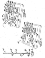
- disposed on a first face 14 of the support, or on the first face and an opposite support face 18, are one or more carriers 16, 26, 36, 116, 126, 136, 16', 26', 36' for one or more analytical agents.
- carriers 16, 26, 36, 116, 126, 136, 16', 26', 36' for one or more analytical agents.
- variations in the location and number of carriers on a support from those described and illustrated, can be used. Thus, variations include fewer or more carriers; for instance, Example 1 includes a description of a useful reagent delivery device having one carrier.
- a carrier or carriers may, for example, provide increased analytical agent loading, provide for physical separation of analytical agents, whether incompatible or not, or provide an additional analytical agent or agents.
- the carriers of a useful reagent delivery device may be water absorbent fibrous pads that maintain structural integrity during analysis, and that are impregnated with analytical agents.
- a suitable fibrous pad should be non-linting, or minimally linting, that is, should release few, if any, fibers into the sample.
- filtration materials that include cellulosic and synthetic fibers.
- useful filtration materials when the carriers are fibrous matrices are illustrated by, but not limited to, Schleicher and Schuell (S&S) 404 and 497 papers, which are cellulosic papers having a thickness of about 0.2 mm, S&S 593 paper, which is a cellulosic paper having a thickness of about 0.35 mm and a water absorbency value of about 2.8 g/100 cm 2 as determined by ASTM 3285 or TAPPI T441 (difference in weight of a 10 x 10 sheet weighed dry, and re-weighed after immersion for 10 seconds in deionized water), S&S 8S paper, which is a rayon paper having a thickness of about 0.35mm and a water absorbency value of about 2.4 g/100 cm 2 , and Lohmann Vliesstoffe OL 50 paper, a viscose rayon paper having a thickness of
- a plurality of pads may form a stacked structure in which case the structure thickness may be up to 3 mm or more.
- Useful carriers are not limited to fibrous pads, and include, but are not limited to, water-insoluble polymers.
- a carrier for an analytical agent may be a suitable water soluble material that by dissolution in water, delivers the analytical agent, and that forms an optically clear solution.
- Suitable water soluble carriers for use in the inventive photometric technology include, but are not limited to, those described in the Fisher et al patent, which describes certain solid or waxy organic polymers as embedding polymers, deposition thereof on a support, and useful relative ratios.
- a mildly acidic carboxylic acid such as 2,2-bis(hydroxymethyl)propionic acid, would be selected as the carrier.
- the water soluble carrier selected it is essential that the water soluble carrier selected not interfere with test accuracy or objectives. Otherwise, the inventive technology, in its broadest aspect, is not constrained by the carrier selected, or in what way or how an analytical agent is carried on a useful reagent delivery device.
- the relative ratio (weight) of analytical agent to carrier will depend upon considerations that include the desired analytical agent loading, and can be expected to vary widely.
- the amount of the DPD salt may exceed that of the carrier, and in particular may substantially exceed the amount of the carrier.
- a ratio (weight) of DPD salt to carrier in the range of about 4:1 to 10:1 and greater may be used.
- An appropriate lower limit for the relative ratio (weight) of an analytical agent to carrier may be 0.01:1 or lower.
- the carrier may be entirely omitted, as illustrated in a variation described in Example 1.
- a solution of the analytical agent in a suitable solvent or solvent system may be deposited on the support, and a drying step follows.
- useful photometric technology is useful for a wide range of analyses, with a limiting feature typically being the use of a reagent delivery device for analytical agent delivery.
- appropriate water soluble analytical agents for use in the present invention vary' widely, although when an impregnated fibrous matrix is used as the carrier, useful analytical agents are beneficially solids, not liquids.
- useful analytical agents include, but are not limited to, agents reactive with analytes of interest, agents reactive with reaction intermediates resulting from reaction with analytes of interest, stabilizing or stabilization-assisting agents, buffer agents, water soluble barrier-forming agents, dispersing agents, wetting agents, and any other reagents that assist or otherwise promote the desired optical analysis.
- Specific analytical agents include, but are not limited to, those described in the Examples that follow, and those described at col. 4, line 25, to col. 5, line 42, of the Fisher et al patent, except for certain of those analytical agents such as dithizone, that are not water soluble. Furthermore, to be useful, an analytical agent cannot interfere with test accuracy or objectives.
- inorganic phosphate analysis using a molybdate/reducing agent combination.
- Phosphate analysis is useful for testing drinking water, pool and spa water, industrial waters including boiler and cooling tower waters, waste water, and for other types of water testing.
- Many U.S.A. cities add about 1 ppm phosphate to drinking water to reduce pipe corrosion.
- Phosphates are a limiting nutrient for algae growth in a pool or pond.
- carriers of useful analytical agent delivery devices are beneficially impregnated with, or otherwise carry, a plurality of appropriate water soluble analytical agents for the analysis of interest.
- a suitable carrier loading of a particular analytical agent will vary depending upon considerations including the particular analytical agent selected, the extent of delivery of the analytical agent, the analyte concentration, and the volume to be analyzed. Thus, for example, a relatively higher analyte concentration or a relatively greater volume can generally be expected to require a relatively higher carrier loading, whereas a relatively lower carrier loading may be appropriate for a relatively lower analyte concentration or relatively smaller volume.
- the loading of particular analytical agents will vary greatly depending upon the analysis of interest, objectives of the analysis including the desired speed of analysis, and the foregoing considerations typically in particular the analyte concentration and volume.
- carrier loading of a particular analytical agent may generally range from about 0.00005 to 0.2 g for a typical 10 ml sample, a higher or lower carrier loading may be appropriate or desired.
- useful reagent delivery devices carry, and deliver into the liquid being analyzed, effective amounts of appropriate analytical agents for the analysis of interest.
- the pad When an impregnated fibrous pad carrier is used, the pad may incorporate a water soluble barrier.
- a benefit is that it tends to seal an analytical agent within the fibrous pad. As a result, abrasive loss of the analytical agent from the pad may be minimized, and the barrier tends to isolate the analytical agent from any user or oxygen contact.
- a mildly acidic, water soluble analytical agent may be used to form the water soluble barrier.
- mildly acidic is meant for purposes of this description, that the barrier-forming agent has a pH in water in the range of about 3 to 5.5.
- a carboxylic acid having a pH in water in the range of about 3 to 4, such as 2,2-bis(hydroxymethyl)propionic acid. This type of agent is not polymeric.
- a useful amount of the barrier-forming agent will vary depending upon the particular agent selected.
- the water soluble barrier-forming agent may be added to an impregnation solution in an amount ranging from about 0.5 to 10 wt.% or more, conveniently from about 1 to 5 wt.%.
- Fibrous pad impregnation may be accomplished in any of several ways.
- a suitable way is to pass a carrier material through an impregnation bath containing the particular chemicals so that the carrier becomes saturated with the impregnation solution.
- the carrier may be then dried at room temperature or at an elevated temperature.
- concentration of the chemicals in an impregnation solution and the residence time of the carrier material in the solution are selected to ensure impregnation of an appropriate loading.
- residence time will vary from about two to forty seconds, depending upon the loading desired and the carrier. If desired or appropriate, the carrier may be dipped more than once to increase the loading.
- a sample may be prepared by conventional procedures that make the analyte of interest available for analysis. Sample pH and any other significant sample parameter should be known or determined, and if not acceptable, the sample should be appropriately adjusted.
- the sample size may vary from 1 ml or less, to 50 ml or more, depending upon the analysis of interest and the analysis objectives. For example, according to US EPA accepted standard methodology for free chlorine analysis, a water sample size of 10 ml is used.
- Useful photometric instruments typically provide a 1 cm or longer light path, and include, but are not limited to, filter photometers, photometers without filters, and spectrophotometers.
- Useful filter photometers include Palintest Pooltest 9 photometers, available from Palintest Ltd, Tyne & Wear, England, and CO7500 Colorimeter photometers available from Industrial Test Systems, Inc., Rock Hill, SC.
- Useful photometers without filters include Oakton Colorimeter C201 and C401 photometers, available from Oakton Instruments, Vernon, IL, Palintest 1000 Chlorometer-Duo photometers, and Hach Pocket Colorimeter II photometers, available from Hach Company, Loveland, CO.
- Waterproof photometric instruments are especially useful when a sample is collected by immersing a portion of the photometric cell or photometric instrument well in an aqueous liquid to be analyzed.
- Useful waterproof photometric instruments include the Oakton Colorimeter C201 and C401 photometers.
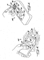
- a simplified schematic view of a portion of a useful waterproof photometric instrument 160' shows an upper housing wall 90 provided with a cell chamber or well 62 for receiving a photometric cell, a suitable light source 92, and a suitable light detector 94.
- Well 62 includes a peripheral wall 96 advantageously provided with an optical window for a light path through the well.
- the well is disposed between the light source and light detector, as is the case for transmissive photometry, and the optical window provides a light path from the light source, through the well, and to the detector.
- the light source is conveniently a light emitting diode capable of emitting a desired wavelength appropriate for the analysis of interest.
- This particular type of photometric instrument structure is used, for example, not only in Oakton Colorimeter C201 and C401 photometers, but also in Palintest 1000 Chlorometer-Duo photometers, and Hach Pocket Colorimeter II photometers.
- Useful filter photometers include an upper housing wall 90 (see Figs. 2 and 3 ) likewise provided with a cell chamber or well 62 advantageously provided with an optical window for a light path through the well.
- the light source emits a wavelength spectrum that is typically directed across a slit (not shown) and spectral filter (not shown) that select a wavelength appropriate for an analysis of interest.
- a broad wavelength spectrum is emitted by a light source (not shown) of useful spectrophotometers, and a monochromator (not shown, typically a prism or grid) and one or more slits (not shown) select a wavelength appropriate for an analysis of interest.
- a monochromator typically a prism or grid
- one or more slits select a wavelength appropriate for an analysis of interest.
- useful photometric instruments advantageously store algorithms appropriate for interpreting the data obtained for an analysis of interest, and other data such as blanking data.
- Photometers such as the Palintest Pooltest 9 photometers, beneficially store a plurality of algorithms specific for a variety of analyses, and include algorithm-selecting touch pads or the like.
- suitable photometric cells may be made of glass or plastic, and as demonstrated in Example 2, may be scratched in the optically important region, and in the case of glass cells, may have significant variability in the geometry and quality of the cell glass.
- Photometric cells having an optical path length of 1 cm or longer such as about 2 cm are typically particularly advantageous for analysis of a low level of an analyte of interest.
- an optical path length of 1 cm or less may benefit the analysis of a high level of a particular analyte.
- a photometric cell is beneficially properly dimensioned and shaped for a generally mating fit within the cell chamber of a selected photometric instrument.
- peripheral wall 156' of a modified photometric cell 150' includes a flange '155', and the photometric cell is dimensioned below the flange to provide two different optical path lengths conveniently provided at about a 90° angle from one another (hidden from view).
- the optical path length selected depends upon, as indicated in Fig. 8 , photometric cell orientation to an optical window alignment mark 80.
- the photometric cell optical path length is conveniently about 2.2 cm, and in a second position (not shown) which is conveniently at about a 90° angle from the first position, the photometric cell optical path length is conveniently about 1 cm.
- Photometric cells of this general type are commercially available from Hach Company. Cells with more than two optical paths lengths may be used.
- a portion of a raised circumferential rim 78 of the modified photometric instrument depicted is omitted to provide an arcuate guide path bounded by, and defined by, a pair of stops 104 within which flange 155 ' may be moved, and the photometric cell may thereby be controllably rotated so that contact of the flange with one of the stops advantageously positions one optical path length relative to the photometric instrument light path, whereas approximately 90° photometric cell rotation and contact of the flange with the other stop advantageously positions the other optical path length relative to the photometric instrument light path.
- a photometric cell containing a suitable volume of an aqueous sample is inserted into a cell chamber of a suitable photometer.
- a suitable volume of the aqueous sample is added to a photometric cell disposed in the cell chamber of a suitable photometer.
- the aqueous sample is added to the cell chamber (or well) of a suitable photometer.
- the sample is beneficially added to the photometric cell or photometric instrument well, by immersion of at least a portion of the photometric cell or photometric instrument well in an aqueous liquid to be analyzed, and thereafter withdrawing the photometric cell or photometric instrument well from the aqueous liquid.
- the photometric cell is sealed in the cell chamber to prevent liquid leakage between the cell chamber wall and the exterior of the photometric cell.
- a water-tight seal may be effected by, for example, use of an O-ring or a suitable adhesive. Adhesion, when used, should be achieved without interfering with the optical window of the cell chamber.
- An illustrative useful silicone-type adhesive is Napa Brand "Clear RTV Silicone" adhesive sealant distributed by Balkamp, Inc., Indianapolis, Indiana.
- the photometric cell or photometric instrument well are leveled as the photometric cell or photometric instrument well is withdrawn from the aqueous liquid.
- the photometer is a waterproof photometer.
- a peripheral wall of the photometric cell may beneficially be provided with a sample-volume controlling aperture, or the photometric cell may be beneficially dimensioned including having a height selected to capture a desired sample volume.
- the sample-volume controlling aperture is advantageously sized to allow escape of excess collected sample from the photometric cell, and advantageously located in the peripheral wall at an appropriate height to capture a desired sample volume. Excess liquid is allowed to escape through the aperture to capture a desired sample volume in the photometric cell.
- An advantageously sized opening is conveniently 7.9 mm (5/16") in diameter. If too small, water surface tension prevents escape of excess liquid. A larger diameter aperture may be used, if desired.
- a blank reading is obtained with the photometric cell in the photometer, and the photometric cell remains in the photometer until after the photometric analysis or analyses of interest. After a desired analysis or analyses, the photometric cell may be withdrawn from the photometric instrument.
- a blank reading is likewise obtained prior to analytical agent addition.
- the delivery end of the reagent delivery device is introduced into the sample to deliver the analytical agent or agents from the reagent delivery device support into the sample, and advantageously a mixing action may be provided, by moving a portion of the support in the sample.
- the delivery end may be moved in the sample in a variety of useful ways, with a back-and-forth or up-and-down motion being typically useful.
- a back-and-forth or up-and-down motion may be typically useful.
- an up-and-down movement may be practical.
- other types of motion such as a back-and-forth motion, may be practical or advantageous.
- a gentle motion may be advantageous to avoid sample loss, for example, when using a photometric instrument well such as is illustrated in Fig. 7 . Accordingly, in certain instances, a gentle motion may be advantageous; whereas, it may be inappropriate to use vigorous shaking or mixing.
- the delivery end may be continuously immersed in, or repeatedly introduced into, the aqueous sample during the time period provided for contact of the aqueous sample with the reagent delivery device.
- the delivery end is continuously immersed.
- an up-and-down motion may prevent continuous immersion, and as a result, a carrier or carriers may be partially or fully withdrawn from the sample during an up stroke and reintroduced into the sample during a down stroke.
- a back-and-forth motion at a gentle rate of about two moves per second may be useful in certain analyses
- an up-and-down motion at a gentle rate of one or two up-and-down strokes per second may be useful in certain other analyses
- other types of mixing action and vigorous motion may be appropriate in other analyses.
- the type of motion is selected to promote analytical agent delivery into the sample, and advantageously to provide an effective mixing action.
- the inventive photometric technology in its broadest aspect, is not constrained by the type of motion selected.
- the time of contact of the aqueous sample with the reagent delivery device is selected to provide sufficient time for analytical agent delivery, it being recognized that depending upon the loading of a particular analytical agent and other considerations including the level of analyte and the desired analysis speed, it may not be necessary or desirable for complete analytical agent delivery to be effected. Additional considerations affecting the time of contact include the sample temperature and the analytical agent carrier medium selected. In this regard, a relatively shorter contact time may be used for a carrier medium that delivers an analytical agent relatively more rapidly, whereas a carrier medium that delivers an analytical agent relatively more slowly is benefitted by a relatively longer contact time. For the same contact time, OL 50 and 8S papers may advantageously provide relatively more analytical agent delivery than 404 paper.
- a preferred contact time may be less than about one minute, with a shorter contact time in the range of about ten to thirty seconds being commercially highly desirable. If desired or appropriate, a longer contact time may be used.
- the inventive photometric technology in its broadest aspect, is not constrained by the duration of the contact time.
- reagent delivery device it may be appropriate or desirable to use more than one reagent delivery device.
- all analytical agents may, if desired, be delivered from a common support (see Example 4), or if a free chlorine value is also desired, an iodide salt may be delivered from a second support (see Example 1).
- any or all analytical agents be delivered using a reagent delivery device.
- analytical agent addition in solid or liquid form may precede or follow use of a reagent delivery device.
- sodium hypochlorite and phosphate buffer may be added in liquid form to convert cyanide to cyanogen chloride, prior to delivery of Konig reactants from a reagent delivery device.
- withdrawal of the reagent delivery device may, depending upon the particular chemistry, be delayed to allow its use for mixing.
- a reagent delivery device is withdrawn from the sample. Thereafter, optical development of the liquid may be allowed to continue for an appropriate period of time prior to photometric analysis. Depending upon the analysis of interest and factors including the particular reagents used, the concentration of the reagents in the liquid being analyzed, the final pH, and the sample temperature, optical development of the liquid may continue for up to about two minutes or even up to 20 minutes or more. It will, of course, be recognized that a relatively more rapid optical development and analysis are commercially desirable.
- analysis values may be adjusted to take into consideration any background optical density by repeating the particular methodology but modified by using an appropriate sample free of the analyte of interest.
- Blanking of a sample and photometric cell, analytical agent delivery and mixing, and photometric analysis may all be carried out in the same photometric cell. Furthermore, for a photometric cell to remain in a photometer during an entire analysis procedure after its insertion for zeroing the instrument, until its removal after a desired reading or readings, avoids concerns about reproducibility due to photometric cell optical density variability, or smudges or fingerprints or water drops on photometric cells as a result of cell removal and re-insertion.
- Chlorine analysis has wide commercial applicability, and is useful for testing drinking water, pool and spa water, aquarium water, industrial and environmental water, and for other types of water testing. Medical applicability includes testing of equipment such as dialysis equipment to confirm removal of chlorine and chloramine contaminants. Furthermore, chlorine analysis has applications to food processing. Chlorine can be present in water as free available chlorine and as combined available chlorine. Both forms can be determined together as total available chlorine.
- support 12 is made of PVC, is 8 mm wide and has a thickness of 0.229 mm (0.009 inches), carrier 16 is 6.35 mm (1/4") long and 8 mm wide, and carriers 26,36 are each 12.7 mm (1 ⁇ 2") long and 8 mm wide.
- the carriers are fibrous pads made of Schleicher and Schuell 497 paper, which has a thickness of about 0.2 mm.
- the DPD salt impregnation solution includes 3.4 wt.% of 2,2-bis(hydroxymethyl)propionic acid, as a water soluble barrier-forming agent. The barrier benefit increases when the DPD salt is used in a high loading.
- a water soluble phosphate buffer solution prepared using an about 2:1 weight ratio of potassium phosphate monobasic anhydrous (4.6 wt.%) to sodium phosphate dibasic anhydrous (2.4 wt.%), to provide a 10 ml sample with a pH in the range of about 6.2 to 6.5.
- Carriers 26,36 are loaded with potassium phosphate monobasic anhydrous to sodium phosphate dibasic anhydrous in a weight ratio of 23:12 to likewise provide a 10 ml sample with a pH in the range of approximately 6.2 to 6.5.
- the DPD sulfate and the phosphate buffer system may be physically separate from one another on the support.
- the impregnation solution for buffer system carriers 26,36 includes 0.8 wt.% of EDTA.
- a second reagent delivery device (not shown) that includes an iodide salt carrier on a support 12 as previously described, is used.
- the iodide salt carrier is 6.35 mm (1/4") long and 8 mm wide, and is impregnated using an impregnation solution containing potassium iodide 99%, and a mixture of 50% PVP k-60 in water (available from ISP Technologies Incorporated, Wayne, NJ) with 50% methanol, in a weight ratio of 13:15.
- the delivery end of the second reagent delivery device is introduced into the 10 ml sample and moved back and forth for 20 seconds to deliver the iodide salt and further mix the sample.
- the second delivery device is withdrawn from the sample, and after a total of three minutes from introducing its delivery end into the sample, the sample color is photometrically read for total chlorine. A total chlorine value of 1.44 mg/l is displayed by the photometer.
- the photometric cell remains in the photometer after its insertion for a blank reading in preparation for the free chlorine reading, until its removal after the total chlorine reading.
- the inventive technology minimizes manipulations, which reduces the time and labor required for analysis, and provides an optimized blank reading, even when a photometric cell exterior is wet or smudged.
- delivery of an effective amount of a useful DPD salt into an aqueous sample and accurate photometric analysis of free chlorine may be achieved within one minute of, beneficially about 20 seconds after, introducing the DPD salt-bearing portion of the support into the sample.
- support 12 carries a mass of 0.0165 g DPD sulfate, and carriers 26,36.
- the DPD sulfate mass is deposited on the support from a solution of 1.176 g DPD sulfate in 0.838 g deionized water and 0.40 g methanol.
- fibrous pad 16 is omitted, and the support carries a mass that is a mixture of DPD sulfate and the propionic acid, and as before, carriers 26,36.
- the mass is deposited from a solution that includes 9.8 wt.% of the propionic acid, and that provides a loading on the support of 0.0164 g DPD sulfate, with a ratio of the DPD sulfate to the propionic acid of about 5:1.
- a water sample size of 10 ml is used for chlorine analysis.
- other sample sizes may, if desired, be used.
- a 25 ml sample may be used.
- the reacted photometry samples are free of undissolved solids and marked by clarity.
- photometer 60 is an Palintest Pooltest 9 photometer.
- Photometric instrument 60 beneficially includes a cell chamber 62 for receiving a photometric cell 50 for optical analysis, an ON touch pad 64, an OFF touch pad 65, a display 68, a touch pad 70 for zeroing the instrument and for display of optical readings, and a slide switch 76 for selecting a 520 nm or 570 nm wavelength.
- a photometric cell holding chamber 63 is not needed in the inventive methodology.
- a touch pad 66 when used to activate the SYSTEM mode, beneficially allows system options such as displacing mg/l or ppm.
- Photometric instrument 60 also beneficially includes a plurality of touch pads 82 each for selecting a desired analysis, including, but not limited to, as marked in Figs. 2 and 3 , for free chlorine analysis (marked “Cl 2 F “), total chlorine analysis (marked “Cl 2 T “), bromine analysis (marked “Br 2 “), ozone analysis (marked “O 3 "), copper analysis (marked “Cu”), pH analysis (marked “pH”), total alkalinity analysis (marked “Alk”), and calcium hardness analysis (marked “Cal”). Also shown in Figs. 2 and 3 are touch pads 84 inoperative for the Pooltest 9 instrument.
- the instrument For free chlorine analysis, the instrument is turned ON using touch pad 64, slide switch 76 is positioned to select a 520 nm wavelength, and the appropriate touch pad 82 for selecting free chlorine analysis, is pressed.
- Three appropriately dimensioned, generally cylindrical photometric cells 50 are selected, one of which is made of light transmissive plastic and two of which are made of light transmissive glass. 10 ml of tap water is added to each photometric cell.
- the plastic cell is inserted into cell chamber 62 and photometer 60 is zeroed by pressing touch pad 70. Thereafter, the plastic cell is removed from cell chamber 62 and capped, then intentionally scratched using a belt sander in the optically important region, then re-inserted in cell chamber 62, and rotated using 1/6th turns to obtain six readings by repeatedly pressing touch pad 70. The readings reveal an average elevated optical value of 0.48 ppm from scratching of the plastic cell.
- one of the glass cells (glass cell #1) is inserted into cell chamber 62 and photometer 60 is zeroed. Then, glass cell #1 is removed from cell chamber 62 and capped, then intentionally scratched using a belt sander in the optically important region, then re-inserted in cell chamber 62, and rotated using 1/6th turns to obtain six readings by repeatedly pressing touch pad 70. The readings reveal an average elevated optical value of 0.34 ppm from scratching of glass cell #1.
- the other glass cell (glass cell #2), which likewise contains 10 ml of tap water, is inserted into cell chamber 62 and photometer 60 is zeroed. Glass cell #2 is then rotated using 1/6th turns to obtain six readings by repeatedly pressing touch pad 70. The readings average 0.00 ppm and thus show no elevated optical value.
- the liquid-containing plastic cell and then liquid-containing glass cell #1 are re-inserted into cell chamber 62, and free chlorine values of 1.14 ppm (plastic cell sample) and 0.90 ppm (glass cell #1 sample) are shown by display 68, by pressing touch pad 70. Adjusting these values by subtracting the average elevated optical values earlier obtained, yields results as follows: 0.66 ppm (1.14 ppm - 0.48 ppm) for the plastic cell sample, and 0.56 ppm (0.90 ppm - 0.34 ppm) for the glass cell #1 sample.
- photometer 160 is an Oakton Colorimeter C201.
- the photometric instrument includes power button 64, mode touch pad 66, display 68, a touch pad 72 for zeroing the photometer, and a touch pad 74 for entry of the selected mode and display of optical readings.
- the C201 instrument provides for analysis of free chlorine and total chlorine, using a wavelength of 525 nm. The analysis desired is selected using mode touch pad 66 to select an appropriate algorithm.
- cell chamber 62 of the C201 instrument is located near an end 86 of the instrument.
- the C201 instrument further includes optical window alignment mark 80.
- An appropriately dimensioned plastic photometric cell 150 is friction fit in cell chamber 62 of waterproof photometer 160, and, without interfering with the optical window of the cell chamber, sealed in the cell chamber using an adhesive sealant commercially sold as Napa Brand "Clear RTV Silicone” distributed by Balkamp, Inc., Indianapolis, Indiana.
- Photometric cell 150 is beneficially dimensioned, when filled to cell rim 154, to capture a 10 ml volume.
- reagent delivery device 10 described in Example 1 for free chlorine analysis, is introduced into the 10 ml sample captured by photometric cell 150, and gently moved back and forth for 20 seconds to deliver the analytical agents from a common support into the sample, and beneficially provide a mixing action.
- reagent delivery device 10 is withdrawn from the photometric cell, and the color of the liquid within photometric cell 150 is immediately read for free chlorine by pressing touch pad 74.
- a free chlorine value of 4.5 ppm is shown by display 68.
- Photometric cell 150 is rinsed using tap water, and after approximately 5 to 6 minutes, again referring in particular to Fig. 4 , the photometric cell is immersed beneath the surface of the chlorine solution at a convenient angle, and then as the photometric cell and photometer end 86 are withdrawn from the chlorine solution, leveled. Repetition of the remainder of the described method, reveals a free chlorine value of 4.2 ppm.
- the photometric cell rim may extend further above raised circumferential rim 78 (omitted for simplification from Fig. 4 ) than is shown in Fig. 5 , of cell chamber 62.
- the device support is made of PVC, is 6.5 mm wide and has a thickness of 0.0229 mm (0.009 inches).
- fibrous pads made of Schleicher and Schuell 404 paper, which has a thickness of approximately 0.2 mm, a water absorbency value of 1.4 g/100 cm 2 , and a basis weight of approximately 80 g/cm 2 .
- On each face of the support is a 6.35 mm (1/4") long and 6.5 mm wide fibrous pad, and a 25.4 mm (1") long and 6.5 mm wide fibrous pad.
- the 6.35 mm (1/4") long pads are located closer than the 25.4 mm (1") long pads to the delivery end of the support.
- the 6.35 mm (1/4") long pads are prepared by impregnating S&S 404 paper using a 13 wt.% solution of sodium thiosulfate (99%) in deionized water, adjusted to a pH of approximately 7.0.
- the 25.4 mm (1") long pads are prepared by impregnating, S&S 404 paper using a 50:50 (on a weight basis) methanol to deionized water impregnation solution containing 1.7 wt.% phenol red (sodium salt), 1.5 wt.% sodium thiosulfate and 1 wt.% potassium chloride, adjusted to a pH of approximately 7.8.
- photometer 160' is an Oakton Colorimeter C401.
- the C401 instrument includes power button 64, mode touch pad 66, display 68, touch pad 72 for zeroing the photometer, and touch pad 74 for entry of the selected mode and display of analytical readings.
- the C401 instrument beneficially provides for analysis of free chlorine, total chlorine, pH and cyanuric acid, using a wavelength of 525 nm. The particular analysis desired is selected using mode touch pad 66 to select an appropriate algorithm.
- cell chamber 62 (or well) of the C401 instrument is located near an end 86 of the instrument.
- Optical window alignment mark 80 (shown in Fig. 7 ) is not needed for this particular Example.
- well 62 when filled to raised circumferential rim 78 (shown only in Figs. 7 and 10 ), contains approximately 22 ml.
- a sample of pool water is taken from Laurel Creek swimming Pool, Rock Hill, SC, and determined using a pH meter to have a pH of 7.78.
- the pH meter is a microcomputer pH/mV/TEMP meter #6171 available from Jenco Instruments, Inc., San Diego, CA.
- reagent delivery device 20 is introduced into the approximately 22 ml sample within well 62, and moved gently back and forth for 20 seconds to deliver the s analytical agents from a common support into the sample, and beneficially provide a mixing action.
- reagent delivery device 20 is withdrawn from the well, and referring again in particular to Fig. 10 , the pH of the liquid within the well is determined by pressing touch pad 74. A pH value of 7.7 is shown by display 68. With the same pool water, repeat of the methodology just described using a fresh reagent delivery device 20, results in a pH value of 7.8 shown by display 68.
- an appropriately dimensioned plastic photometric cell 150' that includes a peripheral wall 156' provided with a sample volume-controlling aperture 158', is friction fit in cell chamber 62 of waterproof photometer 160', which as described in Example 4, is an Oakton Colorimeter C401.
- aperture 158' is conveniently approximately 7.94 mm (5/16 inch) in diameter.
- the photometric cell is dimensioned to provide two different optical path lengths conveniently provided at approximately a 90° angle from one another (hidden from view).
- the optical path length selected depends upon, as indicated in Fig. 8 , photometric cell orientation to optical window alignment mark 80.
- a photometric cell optical path length of 2.2 cm is selected.
- the photometric cell optical path length selected is 1 cm.
- cell chamber 62 of the C401 instrument is located near an end 86 of the instrument.
- a suitably sized container is partially filled with a prepared pool water matrix that contains total chlorine.
- photometric.cell 150' is immersed beneath the surface of the pool water matrix at a convenient angle for collecting a sample.
- Volume-selecting aperture 158' is located in peripheral wall 156' at an appropriate height to capture a 10 ml sample volume after excess sample escapes from the photometric cell through the aperture.
- the photometric cell and photometer end 86 are withdrawn from the pool water matrix, the photometer is leveled, and excess sample is allowed to escape through aperture 158', and, referring in particular to Fig. 8 , with a generally cylindrical, appropriately dimensioned, excess stray light-blocking cap 88 covering the photometric cell, the photometer is zeroed in direct sun light using touch pad 72.
- display 68 gives an error message according to which excess stray light is detected.
- reagent delivery device 40 useful in the present invention, is introduced into the 10 ml pool water matrix sample and moved gently back and forth for 20 seconds to deliver a phosphate buffer system, DPD sulfate and potassium iodide from a common support into the sample, and beneficially provide a mixing action.
- Reagent delivery device 40 corresponds to reagent delivery device 10 described in Example 1, with the potassium iodide-impregnated pad also described in Example 1 affixed to support 12.
- reagent delivery device 40 is withdrawn from the photometric cell, and referring again to Fig. 8 , the photometric cell is covered with cap 88, and the color of the liquid within the photometric cell is analyzed in direct sun light, after a three minute waiting period, for total chlorine by pressing touch pad 74. A total chlorine value of 0.99 mg/l is shown by display 68. When it is attempted to obtain a total chlorine reading in direct sun light without cap 88 covering the photometric cell, display 68 again gives an error message according to which excess stray light is detected.
- Photometric cell 150' is rotatable in cell chamber 62 for selecting a longer or shorter optical path length, of benefit for instance when an over-range reading is found using the longer path length.
- modified photometric cell 150' includes flange 155', and a portion of a raised circumferential rim 78 of the modified photometric instrument is omitted to provide an arcuate guide path bounded by, and defined by, a pair of stops 104 within which flange 155' may be moved and the photometric cell may thereby be controllably rotated so that advantageously flange contact with one of the stops positions one optical path length relative to the photometric instrument light path, whereas flange contact with the other stop positions the other optical path length relative to the photometric instrument light path.
- Example 5 Following the procedure of Example 5 but using a suitably sized container partially filled with pool water taken from Laurel Creek swimming Pool, Rock Hill, SC, cyanuric acid analysis is selected using mode touch pad 66 and pressing touch pad 74, and a 10 ml pool water sample is collected by, as before, immersion of photometric cell 150' and end 86 of a waterproof Oakton Colorimeter C401. Prior to collecting the sample, photometric cell 150' is rinsed twice with the pool water. Thereafter, referring again to Fig. 8 , with cap 88 covering the photometric cell, touch pad 72 is pressed to zero photometer 160', and display 68 reads 0 ppm.
- the reagent delivery device in a convenient embodiment, includes a support made of PVC, is 8 mm wide, and has a thickness of 0.229 mm (0.009 inches). Affixed to both faces of the support are fibrous pads made of S&S 8S paper. Each pad is 25.4 mm (1") long and 8 mm wide. The pad is prepared by impregnating S&S 8S paper using a solution of 15.6 wt.% tris(hydroxymethyl)aminomethane hydrochloride and 5.1 wt.% boric acid in deionized water.
- cyanogen halide reacts with a cyanogen halide-reactive pyridine compound to produce a Konig Reaction intermediate that reacts with a barbituric acid compound to yield a colorimetrically analyzable, colored complex.
- Pyridine, pyridinium salts such as pyridinium trifluoroacetate, and pyridine derivatives such as ⁇ -picoline (4-methylpyridine), nicotinic acid and isonicotinic acid (4-pyridinecarboxylic acid), nicotinamide, and pyridine-3-nitrophthalic acid, are exemplary of pyridine compounds described as useful in the Konig Reaction.
- Barbituric acid barbituric acid derivatives such as 1,3-dimethylbarbituric acid (“1,3-DMB"), and thiobarbituric acid derivatives such as 1,3-diethyl-2-thiobarbituric acid exemplify color-forming barbituric acid compounds described as useful in the Konig Reaction.
- 1,3-DMB 1,3-dimethylbarbituric acid
- thiobarbituric acid derivatives such as 1,3-diethyl-2-thiobarbituric acid exemplify color-forming barbituric acid compounds described as useful in the Konig Reaction.
- the photometrically analyzable, colored complex produced by the Konig Reaction varies in color, and accordingly an appropriate wavelength for photometric analysis varies.
- Konig Reaction-based analyses described in the prior art include, but are not limited to, cyanide analysis, chlorine analysis, and analysis of nicotine metabolites.
- Chloramine-T, N-chlorosuccinimide/ succinimide, and sodium hypochlorite exemplify prior art chlorinating reagents for converting cyanide to cyanogen chloride for cyanide analysis.
- chlorine can be reacted with a water soluble alkali metal cyanide to produce a cyanogen chloride to be reacted with Konig reagents.
- nicotine metabolites may be reacted with a color-forming barbituric acid compound.
- Cyanide can be present in various forms in water. A particular concern is free cyanide ion. In drinking water, at high doses, this form of cyanide inhibits cellular respiration and can result in death. Because of the toxicity to humans, the U.S. EPA has set 0.2 mg/l as the maximum concentration that can be present in drinking water. Sodium cyanide, potassium cyanide and certain other cyanide salts, release cyanide ion when dissolved in water. The usefulness of cyanide analysis is not limited to drinking water, but rather has wide applicability including to plant material, food, blood chemistry, and to many different industrial processes including to industrial wastewater.
- support 12 is made of PVC, is 8 mm wide and has a thickness of 0.229 mm (0.009 inches), and carriers 16', 26' are each 12.7 mm (1 ⁇ 2") long and 8 mm wide.
- Carriers 161,261 are fibrous pads made of Schleicher and Schuell (S&S) 404 paper, and are attached near support end 22 by double-faced adhesive to face 14 of the support.
- S&S Schleicher and Schuell
- S&S 404 paper has a thickness of approximately 0.2 mm, a water absorbency value of 1.4 g/100 cm 2 , and a basis weight of approximately 80 g/cm 2.
- support 12 is as previously described with reference to device 10', and carriers 36' are each 25.4 mm (1") long and 8 mm wide.
- Carriers 36' are fibrous pads made of Schleicher and Schuell (S&S) 404 paper, and are attached near support end 22 by double-faced adhesive to opposite faces 14,18 of the support.
- S&S Schleicher and Schuell
- pads 36' a solution of 12.8 wt.% 1,3-dimethylbarbituric acid, 14.4 wt.% isonicotinic acid and 5.7 wt.% sodium hydroxide having a pH of 6.4, is used to impregnate S&S 404 paper.
- a cyanide standard (sodium cyanide) having a concentration of approximately 0.5 ppm cyanide, is prepared using water free of chlorine and cyanide. The pH is adjusted to 11 using sodium hydroxide solution.
- microcuvette 250 2 ml of the cyanide standard at a temperature of approximately 72°C, is added to a microcuvette 250, and the outside of microcuvette 250 is wiped to be clean and dry. Referring particularly to Fig. 14 , the microcuvette is then inserted into cell chamber 62 of a CO7500 Colorimeter using a mark 252 (especially see Fig. 15 ) as a guide, and photometer 260 is zeroed. A wavelength of 590 nm is used.
- Beneficial photometer features include power button 64, display 68, touch pad 72 for zeroing the photometer, a touch pad 74 for display of analytical readings, a touch pad 98 for continuous readout of changes in absorbance, and a touch pad 102 for selecting whether percent transmission or optical density is displayed,
- reagent delivery device 10' of Fig. 12 is dipped in the 2 ml cyanide standard for 30 seconds to repeatedly immerse carrier pads 16',26' so that the pH is appropriately buffered and cyanide is converted to cyanogen chloride.
- An up and down motion of reagent delivery device 10' is used to deliver the analytical agents from pads 16',26' and provide a mixing action.
- the up-and-down motion is at a gentle constant rate of approximately one up-and-down motion per second.
- device 10' is withdrawn from the microcuvette; and referring particularly to Fig. 15 , beginning within 10 seconds, the delivery end of reagent delivery device 30 is dipped in the liquid in the microcuvette for 30 seconds to repeatedly immerse carrier pads 36'.
- an up and down motion at a gentle constant rate of approximately one up-and-down motion per second is used to deliver the analytical agents from pads 36' and provide mixing.
- device 30 Immediately after 30 seconds contact time with the liquid in the microcuvette, device 30 is withdrawn from the microcuvette. After allowing color development of the liquid in the microcuvette for 3, 5 and 10 minutes from withdrawal of reagent device 30, the color of the liquid in the microcuvette is photometrically evaluated, and the respective optical density readings are as follows: 0.28, 0.42 and 0.63. The increase in optical density from the 3 minute to the 10 minute interval, indicates continuation of the color development. A final pH of 6.8 is measured after the 10 minute interval.
- the microcuvette remains in the photometer during an entire analysis procedure after insertion for zeroing the instrument, until removal after a desired reading or readings. Even so, when highly accurate readings are desired, background optical density needs to be taken into account.
- cyanide reacts with a halogenating agent in an acidic reaction environment to yield a cyanogen halide such as cyanogen chloride.
- the halogenating reaction environment pH is believed to be significant not only in regard to promoting complete and rapid conversion of cyanide to cyanogen halide but also for minimizing cyanogen halide degradation.
- An advantageous reaction environment acidity for the halogenating reaction is an elevated acidic pH significantly greater than pH 2, beneficially in the range of from about 3 to less than 7, preferably about 5 to 6 to promote rapid conversion of cyanide to cyanogen halide and minimize cyanogen halide degradation.
- a reaction environment pH for the halogenating reaction greater than 7.5, is typically detrimental.
- an advantageous final pH for a Konig Reaction is an elevated pH significantly greater than pH 3, beneficially in the range of from about pH 4 to 7.5 depending upon the particular Konig Reaction-based analysis, the Konig reagents selected and the buffer selected.
- a final pH substantially below 4 or substantially in excess of pH 7.5 is typically detrimental for optimum color development and speed of color development.
- support 12 thereof carries, and delivers into a liquid to be analyzed, an effective amount of a suitable water soluble buffer for controlling the reaction environment pH for the halogenating reaction and the reaction environment pH for the Konig Reaction to each be an appropriate elevated pH.
- a suitable water soluble buffer for controlling the reaction environment pH for the halogenating reaction and the reaction environment pH for the Konig Reaction to each be an appropriate elevated pH.
- Beneficial water soluble buffers are known in the prior art, and include, but are not limited to, phosphate and acetate buffers, including modified phosphate buffers.
- sample volume may be used, a preferred sample volume for cyanide analysis is about 2 ml or less.
- a greater sample volume may, if desired, be used; however, as sample volume is increased, considerations such as increased reagent amounts should be taken into account to maintain maximum color development in the desired period of time.
- Sample pH should be known or determined, and if not acceptable, the sample pH should be appropriately adjusted.
- a reagent delivery device for calcium hardness analysis in a convenient embodiment, includes a support made of PVC, is 5.5 mm wide, and has a thickness of 0.229 mm (0.009 inches). Affixed to a face of the support is a fibrous pad made of S&S 8S paper. The pad is 12.7 mm (1/2") long and 5.5 mm wide. The pad is prepared by impregnating S&S 8S paper using a solution of 13.6 wt.% ammonium oxalate in deionized water. The oxalate salt impregnation solution includes 3.0 wt.% of 2,2-bis(hydroxymethyl)propionic acid (98%), as a water soluble barrier-forming agent.
- the delivery end of the calcium hardness reagent delivery device is dipped in the 2 ml sample with a gentle up-and-down motion for 20 seconds. The formation of a fine suspension occurs. After the 20 seconds contact time, the reagent delivery device is withdrawn from the sample, and immediately touch pad 74 is pressed to display the optical density of the liquid in the microcuvette.
- the optical density is 0.54, which according to a standard curve, is equivalent to a calcium hardness value of 52 ppm.
- a reagent delivery device 110 for ammonia analysis in a convenient embodiment, includes a support 12 made of PVC, is 8 mm wide, and has a thickness of 0.229 mm (0.009 inches). Affixed to a first face 14 of the support are spaced apart fibrous pads 116,136 made of S&S 404 paper and S&S 593 paper, respectively, and of 6.35 mm (1/4") length and 12.7 mm (1/2") length, respectively. Fibrous pad 116 is prepared by impregnating S&S 404 paper using a solution of 20 wt.% dichloroisocyanuric acid sodium salt in deionized water.
- Fibrous pad 136 is prepared by impregnating S&S 593 paper using a solution of 24 wt.% sodium nitroferricyanide (III) dihydrate (99%) and 10.3 wt.% salicylic acid sodium salt in deionized water.
- S&S 593 paper is a cellulosic paper having a thickness of 0.36 mm and a water absorbency value of 2.75 g/100 cm 2 .
- Fibrous pad 126 is prepared by impregnating S&S 593 paper using a solution of 21 wt.% potassium hydroxide and 43 wt.% 50% sodium hydroxide in deionized water/methanol (0.8:1 weight basis ratio). All three pads are 8 mm wide.
- delivery end 122 of reagent delivery device 110 is dipped in the 2 ml sample with a gentle up-and-down motion for 30 seconds. After the 30 seconds contact time, the reagent delivery device is withdrawn from the sample, and after a waiting period of 3 minutes, touch pad 74 is pressed to display the optical density of the liquid in the microcuvette. The optical density is 0.27.
- the photometer is turned ON using touch pad 64, slide switch 76 is positioned to select a 520 nm wavelength, and the appropriate touch pad 82 for selecting bromine analysis, is pressed.
- 10 ml of a prepared pool water matrix containing 0 ppm bromine (initial pH 7.5, initial temperature of 23.3°C (74°F)) is added to an appropriately dimensioned, generally cylindrical plastic photometric cell 50, the photometric cell is positioned in cell chamber 62, and photometer 60 is zeroed.
- the delivery end of reagent delivery device 10 described in Example 1 is introduced into the 10 ml sample, and gently moved back and forth for 20 seconds.
- reagent delivery device 10 is withdrawn from the plastic cell, and the color of the liquid in the plastic cell is read for bromine by pressing touch pad 70.
- a bromine value of 0.01 ppm is shown by display 68.
- the final pH is 6.3.
- the photometer is turned ON using touch pad 64, slide switch 76 is positioned to select a 520 nm wavelength, and the appropriate touch pad 82 for selecting copper analysis, is pressed.
- the reagent delivery device for copper analysis in a convenient embodiment, includes a support made of PVC, is 8 mm wide, and has a thickness of 0.229 mm (0.009 inches). Affixed to opposing faces of the support are fibrous pads made of S&S 404 paper. Each pad is 25.4 mm (1") long and 8 mm wide. The pads are prepared by impregnating S&S 404 paper using a solution of 8 wt.% 4,4'-dicarboxy-2,2'-biquinolone potassium salt and 5.5 wt.% sodium metabisulfite in distilled water/ethanol (27:1 weight basis ratio), adjusted to a pH of 6.5.
- the photometer is turned ON using touch pad 64, slide switch 76 is positioned to select a 570 nm wavelength, and the appropriate touch pad 82 for selecting total alkalinity analysis, is pressed.
- the reagent delivery device for total alkalinity analysis in a convenient embodiment, includes a support made of PVC, is 8 mm wide, and has a thickness of 0.229 mm (0.009 inches). Affixed to the opposing faces of the support are 25.4 mm (1") long fibrous pads made of S&S 404 paper. Each pad is 8 mm wide. The pads are prepared by impregnating S&S 404 paper using a solution of 0.72 wt.% bromocresol green sodium salt, 18.93 wt.% glutaric acid, and 3.69 wt.% glycine in deionized water/methanol (1.3:1 weight basis ratio), adjusted to a pH of 3.5.
Landscapes
- Physics & Mathematics (AREA)
- Health & Medical Sciences (AREA)
- Chemical & Material Sciences (AREA)
- Life Sciences & Earth Sciences (AREA)
- Pathology (AREA)
- Immunology (AREA)
- General Physics & Mathematics (AREA)
- Analytical Chemistry (AREA)
- Biochemistry (AREA)
- General Health & Medical Sciences (AREA)
- Chemical Kinetics & Catalysis (AREA)
- Plasma & Fusion (AREA)
- Engineering & Computer Science (AREA)
- Molecular Biology (AREA)
- Spectroscopy & Molecular Physics (AREA)
- Investigating Or Analysing Materials By The Use Of Chemical Reactions (AREA)
- Optical Measuring Cells (AREA)
- Investigating Or Analyzing Non-Biological Materials By The Use Of Chemical Means (AREA)
Description
- This patent application is a continuation-in-part of pending
U.S. Patent Application Ser. No. 10/949,315, filed on September 27, 2004 U.S. Patent Application Ser. No. 11/117,536, filed on April 29, 2005 - This invention relates to photometric analysis of liquids.
- Photometric analysis of liquids typically uses two photometric cells (or cuvettes) or one photometric cuvette. When two matched cuvettes are used, a first cuvette with sample is used as a blank to zero the photometric instrument, and then an optical value for an analyte of interest is obtained using a matched cuvette with sample to which analytical agents have been added. It is recognized that nicks and scratches from handling may cause an optical mismatch between cuvettes and introduce error into the test results. Accordingly, it is customary to discard matched cuvettes that have been nicked or scratched.
- When one cuvette is used, the cuvette with sample is inserted into the photometric instrument as a blank to zero the instrument, and after zeroing the instrument and removing the cuvette, analytical agents are added to the sample, and then the cuvette is re-inserted into the instrument to obtain an optical value for an analyte of interest. It is recognized that because cuvette orientation in a photometric instrument will greatly affect test results, a cuvette should always be inserted into the instrument so that the cuvette has the same orientation to the light path, and that variability in the geometry and quality of the glassware can cause variability in results.
- Furthermore, it is recognized regardless whether one or two cuvettes are used, that a cuvette exterior should be free of smudges or fingerprints or water droplets to ensure accurate readings. Useful photometric instruments include filter photometers, photometers without filters, and spectrophotometers, and typically provide an optical path length of 1 cm or longer. Photometric analysis of liquids includes colorimetric analysis and turbidimetric analysis. By "turbidimetric analysis" is meant, for purposes of this description, analysis based upon measuring the effect of fine suspended particles on a light beam.
- As illustrated by
U.S. Patent No. 4,353,869 to Guth , it has been described to photometrically test for intoxication by inserting an end of a bubbler tube into an analytical agent-containing liquid contained in a glass ampoule, by then inserting the resulting assembly into a photooptical apparatus, by then nulling the photooptical apparatus, and by then bubbling deep lung breath from a suspect through the end of the bubbler tube into the liquid and taking a photometric reading. A mixing action is provided by the deep lung air bubbling through the analytical agent-containing liquid. - A pH/conductivity, water resistant meter that includes a conductivity cell with built-in electrodes and a pH sensor well, is commercially available from Myron L Company of Carlsbad, CA. The pH sensor includes a protective cap. The meter is not useful for photometric analysis.
- Also described in the prior art, as illustrated by
U.S. Patent Nos. 3,937,613 to Rosicky and4,275,031 to Fischer et al , are reagent delivery devices that include a support such as an inert plastic strip or the like, and that release certain analytical agents into a sample for colorimetric evaluation of sample color. The sufficiently rigid supports of such devices may be used to stir the sample. Fisher et al teach the use of certain embedding polymers that dissolve in water to release analytical agents and form an optically clear solution, and disclose a broad range of embedding polymers, analytical agents, and analyses. - Also described in the prior art, as illustrated by
EP 469772 - Also described in the prior art, as exemplified by
U.S. Patent No. 6,249,345 to Kraack et al , is an essentially box-shaped cuvette that includes two different optical path lengths, and allows changing from one optical path length to another. - Also described in the prior art, as illustrated by
U.S Patent No. 3,833,864 to Kiess , is a combined blood constituent and prothrombin time analytical method comprising disposing a photometric cell containing a sample in a photometric instrument, using an open cavity condition to simulate a reference, adding a reagent to the photometric cell, and photometrically analyzing. - As can be recognized from the foregoing description of photometric analysis prior art, there continues to be a need for improved photometric analysis of liquids. It would be beneficial to minimize manipulations, reduce the time and labor required for analysis, and to reduce variability of measurements. It would be beneficial to avoid the need for matched cuvettes, and to avoid any concern about the use of cuvettes with nicks or scratches.
- In accordance with a first aspect, the present invention provides a photometric analytical method comprising immersing in an aqueous liquid to be analyzed at least a portion of a photometric cell disposed in a photometric instrument or at least a portion of a photometric instrument cell chamber, to collect an aqueous sample; thereafter obtaining a blank reading for the photometric cell or photometric instrument cell chamber containing the aqueous sample; then moving a portion of a support of a reagent delivery device in the aqueous sample to deliver from the reagent delivery device support into the aqueous sample, at least one water soluble analytical agent for photometric analysis and also to provide a mixing action, wherein the analytical agent is delivered into, and the mixing occurs in, the photometric cell and the photometric cell is disposed in the photometric instrument, or the analytical agent is delivered into, and the mixing occurs in, the photometric instrument cell chamber; thereafter withdrawing the support from the resulting liquid; and thereafter photometrically analyzing the liquid in the photometric cell or the photometric instrument cell chamber; wherein when a photometric cell is used, the photometric cell remains in the photometric instrument after the blank reading at least until after the photometric analysis.
- Depending upon the analysis, the analyte of interest may be reacted, prior to the analytical agent delivery step, to yield a useful reaction product, and the reaction product may thereafter be reacted to produce a photometrically analyzable liquid. In other analyses, an analytical agent delivered from a reagent delivery device, reacts with the analyte of interest to produce a photometrically analyzable liquid. In yet other analyses, an analytical agent reactive with the analyte of interest to produce a photometrically analyzable liquid, is added prior to the analytical agent delivery step.
- It will be recognized by one skilled in the art upon consideration of the detailed description of the inventive photometric technology, that yet other analyses within the scope of the inventive photometric technology, involve variations from those just described, and furthermore that although a reagent delivery device typically delivers a reactive analytical agent, an analytical agent delivered from a reagent delivery device, may merely assist or otherwise promote a desired optical analysis. Moreover, depending upon the analysis of interest or as appropriate or desired, more than one reagent delivery device may be used to deliver a useful analytical agent or agents prior to the photometric analysis step.
- Prior to the blank reading, in the case of a particularly useful photometric cell that provides for selection between different optical path lengths, a desired optical path length may beneficially be selected by photometric cell rotation.
- The sample may be beneficially added to the photometric cell or photometric instrument well, by immersing a portion of the photometric cell or photometric instrument well in a bulk volume of an aqueous liquid to be analyzed, such as swimming pool or spa water, and , thereafter withdrawing the photometric cell or photometric instrument well from the aqueous liquid. The photometric instrument may be a waterproof photometric instrument. By the term "waterproof" is meant, for purposes of this description, impervious to water, and is to be distinguished from water-resistant. The imperviousness of a waterproof photometric instrument beneficially protects function-critical instrument components, including but not limited to, electronic and power components, from contact with water. The photometric instrument well of a particularly beneficial waterproof photometric instrument, is located near an end of the photometric instrument.
- When a photometric cell is immersed for sample collection, a peripheral wall of the photometric cell may beneficially be provided with a sample-volume controlling aperture, or the photometric cell may be beneficially dimensioned including having a height selected to capture a desired sample volume. The sample-volume controlling aperture is advantageously sized to allow escape of excess collected sample from the photometric cell through the aperture. Excess liquid is allowed to escape through the aperture to capture a desired sample volume in the photometric cell.
- A particularly useful photometric cell that provides more than one optical path length is disposed in a photometric instrument, and an optical path length is selected by rotation of the photometric cell. Beneficially, if desired or appropriate for the analysis of interest, for instance when an over-range result is found, a shorter optical path length for estimation, may be selected by rotation of the photometric cell. Thereafter, the same analytical agent may be added to a fresh liquid sample using the newly selected optical path length, and photometric analysis effected.
- Also disclosed is a photometric apparatus comprising a photometric instrument provided with a cell chamber for receiving a photometric cell that provides more than one optical path length, wherein the photometric cell is rotatably disposed in the photometric instrument cell chamber wherein in a first orientation of rotatably disposed photometric cell relative to a light path of photometric instrument, a first optical path length of the photometric cell is selected, and wherein in a second orientation of rotatably disposed photometric cell relative to the light path of photometric instrument, a second optical path length of the photometric cell is selected; and wherein a peripheral wall of rotatably disposed photometric cell comprises a flange, and rotation of the photometric cell is limited by contact of the photometric cell flange with a stop member.
- Advantageously, useful cuvettes or a useful photometric instrument well may be discolored, nicked or scratched in the optically important region. Prior to this invention, discolored, nicked or scratched cuvettes have normally been discarded.
- In the drawing and in detailed description of the invention that follows, there are essentially shown and described only preferred embodiments of this invention, simply by way of illustration of the best mode contemplated of carrying out this invention. As will be realized, this invention is capable of other and different embodiments, and its several details are capable of modification in various respects, all without departing from the invention. Accordingly, the drawing and the detailed description are to be regarded as illustrative in nature, and not as restrictive.
- Reference is now made to the accompanying drawing, which forms a part of the specification of the present invention.
-
Fig. 1 is a longitudinal cross-sectional view of a reagent delivery device useful in the present invention; -
Fig. 2 is a perspective view of a useful photometric instrument, with a photometric cell inserted in the cell chamber, -
Fig. 3 is a perspective view of the photometric instrument ofFig. 2 , with the delivery end of the reagent delivery device ofFig. 1 in the photometric cell; -
Fig. 4 is a perspective view of a useful waterproof photometric instrument, with a photometric cell inserted in the cell chamber, showing the photometric cell immersed to collect a sample for analysis; -
Fig. 5 is a more detailed perspective view of the photometric instrument ofFig. 4 , illustrating that a desired sample volume is captured by the immersion, and showing the delivery end of the reagent delivery device ofFig. 1 in the photometric cell; -
Fig. 6 is a perspective view of another useful waterproof photometric instrument but without a photometric cell in the cell chamber (or well), showing the well immersed to collect a sample for analysis; -
Fig. 7 is a more detailed perspective view of the photometric instrument ofFig. 6 , illustrating that a desired sample volume is captured by the immersion, and showing the delivery end of a reagent delivery device for optical analysis, in the photometric instrument well; -
Fig. 8 is a perspective view of a modification of the waterproof instrument ofFigs. 6 and 7 , showing a modified photometric cell inserted in the cell chamber and exposed to view by exploded positioning of an interfering light-blocking cap, and illustrating the rotatable photometric cell in a first position relative to the photometric instrument light path, and that the modified instrument and photometric cell provide controlled photometric cell positioning for selection of a desired photometric cell optical path length; -
Fig. 9 is a perspective view of the photometric instrument ofFigs. 6 and 7 without the light-blocking cap and other beneficial features shown inFig. 8 , illustrating that a desired sample volume is captured by a volume-controlling aperture of the photometric cell depicted, and the delivery end of a reagent delivery device for optical analysis, in the photometric cell; -
Fig. 10 is a partial cross-sectional simplified, schematic illustration of a portion of the photometric instrument ofFigs. 6 and 7 , showing the photometric instrument well containing a collected sample, and a light path from a light source, through the well, and to a light detector; -
Figs. 11 to 13 are longitudinal cross-sectional views of three additional reagent delivery devices useful in the present invention; -
Fig. 14 is a perspective view of another useful photometric instrument, with a suitable microcuvette inserted in the cell chamber; and -
Fig. 15 is a partial, enlarged view of the photometric instrument ofFig: 14 , with the delivery end of the reagent delivery device ofFig. 13 in the microcuvette. - The inventive photometric technology is useful for a wide range of analyses, with a limiting features typically being the use of a reagent delivery device for analytical agent delivery. As a result, the inventive photometric technology may be touch-free. Accordingly, user handling of reagent solutions or tablets or powders or glass ampoules may be eliminated. In such case, there are no tablets to crush or dissolve, powders to spill, and glass ampoules to break, there is no potential for injury from broken glass ampoules, and any concern about the effect of any reagent spillage or loss, on precision is removed.
- However, it is not a necessary feature of the inventive photometric, technology, in its broadest aspect, that any or all analytical agents be delivered using a reagent delivery device. To the contrary, if appropriate or desired, analytical agents may be added prior to, or after, analytical agent delivery using a reagent delivery device. A further consideration relative to applications of the inventive technology, is that when an impregnated fibrous matrix is used as the analytical agent carrier, useful analytical agents are beneficially solids, not liquids.
- Beneficially, manipulations can be minimized, the time and labor required for analysis can be reduced, and variability of measurements can be reduced. Advantageously, concerns about cuvette orientation in a photometric instrument, or about the use of nicked, scratched or discolored cuvettes are overcome.
- The inventive photometric technology has wide commercial applicability, and is useful for testing drinking water, pool and spa water, aquarium water, pond water, industrial and environmental water, and for other types of water testing. Medical applicability includes biochemical and diagnostic testing based upon analysis of an aqueous liquid, including for example, urine testing, and furthermore includes testing of equipment such as dialysis equipment to confirm removal of chlorine and chloramine contaminants. Further applications include food processing, and analysis of plant material.
- Referring to
Figures 1 and11-13 of the drawing; illustrative analytical agent delivery devices are shown. As illustrated, an analytical agent delivery device useful in the present invention, conveniently includes an elongated support or handle member 12, which may beneficially be a plastic strip or other suitable support of sufficient rigidity for providing stiffness for an effective mixing action. As a result, the support may be used not only as a carrier for analytical agents, but also a mixing action may be provided by moving a portion of the support in the sample. - Typically, when a plastic strip is used, the support will range in thickness from about 0.1524 to 0.508 mm (0.006 to 0.020 inches). However, the support thickness may, if appropriate or desired, vary from this range depending upon the particular goal or goals for its application. When a sample volume of about 2 ml or less is analyzed, and accordingly use of a microcuvette is advantageous, a practical width for support 12 will typically range from about 4 to 10 mm. The width of the support may be 12 mm or more when a larger sample volume is analyzed, or may vary from this range, if desired or appropriate, depending upon the particular goal or goals for its application.
- Any other suitable support, such as a rod, in particular of square or rectangular cross-section, may be used if desired or appropriate. Although an elongated shape of the support is advantageous for delivery and mixing, it will be recognized that other shapes may be used for the support. The support may be made from various inert materials, with preferred materials for economy being available at low cost. Suitably, the support may be made of, for example, PVC.
- An analytical agent delivery device useful in the present invention, beneficially provides for touch-free delivery of appropriate water soluble analytical agents for the analysis of interest into the liquid being analyzed. Conveniently, to this end, and referring again for sake of illustration to
Figs. 1 and11 to 13 , disposed on afirst face 14 of the support, or on the first face and anopposite support face 18, are one ormore carriers - Conveniently, the carriers of a useful reagent delivery device may be water absorbent fibrous pads that maintain structural integrity during analysis, and that are impregnated with analytical agents. A suitable fibrous pad should be non-linting, or minimally linting, that is, should release few, if any, fibers into the sample.
- Materials useful as suitable fibrous pads are known, and include filtration materials that include cellulosic and synthetic fibers. Depending upon the analysis of interest, useful filtration materials when the carriers are fibrous matrices, are illustrated by, but not limited to, Schleicher and Schuell (S&S) 404 and 497 papers, which are cellulosic papers having a thickness of about 0.2 mm, S&S 593 paper, which is a cellulosic paper having a thickness of about 0.35 mm and a water absorbency value of about 2.8 g/100 cm2 as determined by ASTM 3285 or TAPPI T441 (difference in weight of a 10 x 10 sheet weighed dry, and re-weighed after immersion for 10 seconds in deionized water), S&S 8S paper, which is a rayon paper having a thickness of about 0.35mm and a water absorbency value of about 2.4 g/100 cm2, and Lohmann Vliesstoffe OL 50 paper, a viscose rayon paper having a thickness of about 0.4 mm.
- Depending upon the analysis and analytical agent, a plurality of pads, whether impregnated or not, may form a stacked structure in which case the structure thickness may be up to 3 mm or more. Useful carriers are not limited to fibrous pads, and include, but are not limited to, water-insoluble polymers.
- Furthermore, depending upon the analysis and analytical agent, instead of a fibrous matrix, a carrier for an analytical agent may be a suitable water soluble material that by dissolution in water, delivers the analytical agent, and that forms an optically clear solution. Suitable water soluble carriers for use in the inventive photometric technology include, but are not limited to, those described in the Fisher et al patent, which describes certain solid or waxy organic polymers as embedding polymers, deposition thereof on a support, and useful relative ratios.
- However, if free chlorine analysis within one minute of introducing a water soluble carrier for a DPD salt into a sample, is desired, a mildly acidic carboxylic acid such as 2,2-bis(hydroxymethyl)propionic acid, would be selected as the carrier. Thus, it is essential that the water soluble carrier selected not interfere with test accuracy or objectives. Otherwise, the inventive technology, in its broadest aspect, is not constrained by the carrier selected, or in what way or how an analytical agent is carried on a useful reagent delivery device.
- When an analytical agent is deposited on a support with a suitable water soluble material as the carrier, the relative ratio (weight) of analytical agent to carrier will depend upon considerations that include the desired analytical agent loading, and can be expected to vary widely. Beneficially, to obtain an excess loading, for instance, of DPD salt, the amount of the DPD salt may exceed that of the carrier, and in particular may substantially exceed the amount of the carrier. For example, a ratio (weight) of DPD salt to carrier in the range of about 4:1 to 10:1 and greater may be used. An appropriate lower limit for the relative ratio (weight) of an analytical agent to carrier may be 0.01:1 or lower.
- Moreover, depending upon the analytical agent, if desired or appropriate, the carrier may be entirely omitted, as illustrated in a variation described in Example 1. To this end, a solution of the analytical agent in a suitable solvent or solvent system may be deposited on the support, and a drying step follows.
- As previously described, the inventive photometric technology is useful for a wide range of analyses, with a limiting feature typically being the use of a reagent delivery device for analytical agent delivery. Thus, appropriate water soluble analytical agents for use in the present invention vary' widely, although when an impregnated fibrous matrix is used as the carrier, useful analytical agents are beneficially solids, not liquids. Furthermore, useful analytical agents include, but are not limited to, agents reactive with analytes of interest, agents reactive with reaction intermediates resulting from reaction with analytes of interest, stabilizing or stabilization-assisting agents, buffer agents, water soluble barrier-forming agents, dispersing agents, wetting agents, and any other reagents that assist or otherwise promote the desired optical analysis. Specific analytical agents include, but are not limited to, those described in the Examples that follow, and those described at col. 4, line 25, to col. 5, line 42, of the Fisher et al patent, except for certain of those analytical agents such as dithizone, that are not water soluble. Furthermore, to be useful, an analytical agent cannot interfere with test accuracy or objectives.
- Specifically disclosed by Fisher et al, at col. 5, lines 10-11, is inorganic phosphate analysis using a molybdate/reducing agent combination. Phosphate analysis is useful for testing drinking water, pool and spa water, industrial waters including boiler and cooling tower waters, waste water, and for other types of water testing. Many U.S.A. cities add about 1 ppm phosphate to drinking water to reduce pipe corrosion. Phosphates are a limiting nutrient for algae growth in a pool or pond. As indicated by Fisher et al, the chemistry of reacting molybdate ions with phosphate ions to yield a phosphate molybdate complex, and reducing the phosphate molybdate complex to yield a reduced complex for colorimetric analysis, is known in the prior art.
- As can be thus understood, carriers of useful analytical agent delivery devices are beneficially impregnated with, or otherwise carry, a plurality of appropriate water soluble analytical agents for the analysis of interest. A suitable carrier loading of a particular analytical agent will vary depending upon considerations including the particular analytical agent selected, the extent of delivery of the analytical agent, the analyte concentration, and the volume to be analyzed. Thus, for example, a relatively higher analyte concentration or a relatively greater volume can generally be expected to require a relatively higher carrier loading, whereas a relatively lower carrier loading may be appropriate for a relatively lower analyte concentration or relatively smaller volume. As can be readily recognized, the loading of particular analytical agents will vary greatly depending upon the analysis of interest, objectives of the analysis including the desired speed of analysis, and the foregoing considerations typically in particular the analyte concentration and volume. Thus, although carrier loading of a particular analytical agent may generally range from about 0.00005 to 0.2 g for a typical 10 ml sample, a higher or lower carrier loading may be appropriate or desired. In any event, useful reagent delivery devices carry, and deliver into the liquid being analyzed, effective amounts of appropriate analytical agents for the analysis of interest.
- When an impregnated fibrous pad carrier is used, the pad may incorporate a water soluble barrier. A benefit is that it tends to seal an analytical agent within the fibrous pad. As a result, abrasive loss of the analytical agent from the pad may be minimized, and the barrier tends to isolate the analytical agent from any user or oxygen contact.
- A mildly acidic, water soluble analytical agent may be used to form the water soluble barrier. By "mildly acidic" is meant for purposes of this description, that the barrier-forming agent has a pH in water in the range of about 3 to 5.5. Especially illustrative is a carboxylic acid having a pH in water in the range of about 3 to 4, such as 2,2-bis(hydroxymethyl)propionic acid. This type of agent is not polymeric.
- A useful amount of the barrier-forming agent will vary depending upon the particular agent selected. The water soluble barrier-forming agent may be added to an impregnation solution in an amount ranging from about 0.5 to 10 wt.% or more, conveniently from about 1 to 5 wt.%.
- Fibrous pad impregnation may be accomplished in any of several ways. A suitable way is to pass a carrier material through an impregnation bath containing the particular chemicals so that the carrier becomes saturated with the impregnation solution. The carrier may be then dried at room temperature or at an elevated temperature. Advantageously, the concentration of the chemicals in an impregnation solution and the residence time of the carrier material in the solution are selected to ensure impregnation of an appropriate loading. Generally speaking, residence time will vary from about two to forty seconds, depending upon the loading desired and the carrier. If desired or appropriate, the carrier may be dipped more than once to increase the loading.
- Depending upon the analysis of interest, prior to or in preparation for analysis, a sample may be prepared by conventional procedures that make the analyte of interest available for analysis. Sample pH and any other significant sample parameter should be known or determined, and if not acceptable, the sample should be appropriately adjusted.
- The sample size may vary from 1 ml or less, to 50 ml or more, depending upon the analysis of interest and the analysis objectives. For example, according to US EPA accepted standard methodology for free chlorine analysis, a water sample size of 10 ml is used.
- Useful photometric instruments typically provide a 1 cm or longer light path, and include, but are not limited to, filter photometers, photometers without filters, and spectrophotometers. Useful filter photometers include Palintest Pooltest 9 photometers, available from Palintest Ltd, Tyne & Wear, England, and CO7500 Colorimeter photometers available from Industrial Test Systems, Inc., Rock Hill, SC. Useful photometers without filters include Oakton Colorimeter C201 and C401 photometers, available from Oakton Instruments, Vernon, IL, Palintest 1000 Chlorometer-Duo photometers, and Hach Pocket Colorimeter II photometers, available from Hach Company, Loveland, CO.
- Waterproof photometric instruments are especially useful when a sample is collected by immersing a portion of the photometric cell or photometric instrument well in an aqueous liquid to be analyzed. Useful waterproof photometric instruments include the Oakton Colorimeter C201 and C401 photometers.
- With reference to
Fig. 10 , a simplified schematic view of a portion of a useful waterproof photometric instrument 160' shows anupper housing wall 90 provided with a cell chamber or well 62 for receiving a photometric cell, a suitable light source 92, and a suitable light detector 94. Well 62 includes aperipheral wall 96 advantageously provided with an optical window for a light path through the well. Conveniently, the well is disposed between the light source and light detector, as is the case for transmissive photometry, and the optical window provides a light path from the light source, through the well, and to the detector. The light source is conveniently a light emitting diode capable of emitting a desired wavelength appropriate for the analysis of interest. This particular type of photometric instrument structure is used, for example, not only in Oakton Colorimeter C201 and C401 photometers, but also in Palintest 1000 Chlorometer-Duo photometers, and Hach Pocket Colorimeter II photometers. - Useful filter photometers include an upper housing wall 90 (see
Figs. 2 and 3 ) likewise provided with a cell chamber or well 62 advantageously provided with an optical window for a light path through the well. In filter photometers, the light source emits a wavelength spectrum that is typically directed across a slit (not shown) and spectral filter (not shown) that select a wavelength appropriate for an analysis of interest. - Similarly, a broad wavelength spectrum is emitted by a light source (not shown) of useful spectrophotometers, and a monochromator (not shown, typically a prism or grid) and one or more slits (not shown) select a wavelength appropriate for an analysis of interest. It will be recognized by one skilled in the photometric art that the foregoing description of useful photometric instruments has been simplified for sake of brevity.
- Moreover, useful photometric instruments advantageously store algorithms appropriate for interpreting the data obtained for an analysis of interest, and other data such as blanking data. Photometers such as the Palintest Pooltest 9 photometers, beneficially store a plurality of algorithms specific for a variety of analyses, and include algorithm-selecting touch pads or the like.
- In accordance with the invention, suitable photometric cells may be made of glass or plastic, and as demonstrated in Example 2, may be scratched in the optically important region, and in the case of glass cells, may have significant variability in the geometry and quality of the cell glass. Photometric cells having an optical path length of 1 cm or longer such as about 2 cm, are typically particularly advantageous for analysis of a low level of an analyte of interest. On the other hand, an optical path length of 1 cm or less may benefit the analysis of a high level of a particular analyte. In any event, a photometric cell is beneficially properly dimensioned and shaped for a generally mating fit within the cell chamber of a selected photometric instrument.
- A particularly beneficial photometric cell is shown in
Fig. 8 . Advantageously, peripheral wall 156' of a modified photometric cell 150' includes a flange '155', and the photometric cell is dimensioned below the flange to provide two different optical path lengths conveniently provided at about a 90° angle from one another (hidden from view). The optical path length selected depends upon, as indicated inFig. 8 , photometric cell orientation to an opticalwindow alignment mark 80. In a first position of the photometric cell relative to the photometric instrument light path, the photometric cell optical path length is conveniently about 2.2 cm, and in a second position (not shown) which is conveniently at about a 90° angle from the first position, the photometric cell optical path length is conveniently about 1 cm. Photometric cells of this general type (not including a volume-controlling aperture 158') are commercially available from Hach Company. Cells with more than two optical paths lengths may be used. - With continued reference to
Fig. 8 , a portion of a raisedcircumferential rim 78 of the modified photometric instrument depicted, is omitted to provide an arcuate guide path bounded by, and defined by, a pair of stops 104 within which flange 155' may be moved, and the photometric cell may thereby be controllably rotated so that contact of the flange with one of the stops advantageously positions one optical path length relative to the photometric instrument light path, whereas approximately 90° photometric cell rotation and contact of the flange with the other stop advantageously positions the other optical path length relative to the photometric instrument light path. - In accordance with a first aspect of a beneficial inventive photometric analysis method, a photometric cell containing a suitable volume of an aqueous sample, is inserted into a cell chamber of a suitable photometer. Alternatively in accordance with a second aspect of a beneficial inventive photometric analysis method, a suitable volume of the aqueous sample is added to a photometric cell disposed in the cell chamber of a suitable photometer. In accordance with a modification of the second aspect, the aqueous sample is added to the cell chamber (or well) of a suitable photometer.
- In accordance with the second inventive aspect, the sample is beneficially added to the photometric cell or photometric instrument well, by immersion of at least a portion of the photometric cell or photometric instrument well in an aqueous liquid to be analyzed, and thereafter withdrawing the photometric cell or photometric instrument well from the aqueous liquid. Advantageously, in accordance with the second inventive aspect when a photometric cell is immersed for sample collection, the photometric cell is sealed in the cell chamber to prevent liquid leakage between the cell chamber wall and the exterior of the photometric cell. A water-tight seal may be effected by, for example, use of an O-ring or a suitable adhesive. Adhesion, when used, should be achieved without interfering with the optical window of the cell chamber. An illustrative useful silicone-type adhesive is Napa Brand "Clear RTV Silicone" adhesive sealant distributed by Balkamp, Inc., Indianapolis, Indiana.
- Advantageously, in accordance with the second inventive aspect, after collection of a sample, the photometric cell or photometric instrument well are leveled as the photometric cell or photometric instrument well is withdrawn from the aqueous liquid. Beneficially, in accordance with the second inventive aspect, the photometer is a waterproof photometer.
- When a photometric cell is immersed for sample collection, a peripheral wall of the photometric cell may beneficially be provided with a sample-volume controlling aperture, or the photometric cell may be beneficially dimensioned including having a height selected to capture a desired sample volume. The sample-volume controlling aperture is advantageously sized to allow escape of excess collected sample from the photometric cell, and advantageously located in the peripheral wall at an appropriate height to capture a desired sample volume. Excess liquid is allowed to escape through the aperture to capture a desired sample volume in the photometric cell.
- An advantageously sized opening is conveniently 7.9 mm (5/16") in diameter. If too small, water surface tension prevents escape of excess liquid. A larger diameter aperture may be used, if desired.
- Beneficially, in accordance with the invention when a photometric cell is used, a blank reading is obtained with the photometric cell in the photometer, and the photometric cell remains in the photometer until after the photometric analysis or analyses of interest. After a desired analysis or analyses, the photometric cell may be withdrawn from the photometric instrument. Beneficially, in accordance with the modification when the photometric instrument well is used instead of a photometric cell, a blank reading is likewise obtained prior to analytical agent addition.
- With a desired volume of the aqueous sample in the photometric cell or photometer well, when beneficially using a useful reagent delivery device, the delivery end of the reagent delivery device is introduced into the sample to deliver the analytical agent or agents from the reagent delivery device support into the sample, and advantageously a mixing action may be provided, by moving a portion of the support in the sample.
- The delivery end may be moved in the sample in a variety of useful ways, with a back-and-forth or up-and-down motion being typically useful. In the case of a small sample volume when use of a microcuvette is beneficial, an up-and-down movement may be practical. For a larger sample volume, other types of motion such as a back-and-forth motion, may be practical or advantageous.
- During certain reactions, for example, the conversion of cyanide to cyanogen halide, it is beneficial to minimize introducing air into the aqueous sample. Thus, a mixing action consistent with minimizing interference with a reaction or analysis, should be used when appropriate. Similarly, a gentle motion may be advantageous to avoid sample loss, for example, when using a photometric instrument well such as is illustrated in
Fig. 7 . Accordingly, in certain instances, a gentle motion may be advantageous; whereas, it may be inappropriate to use vigorous shaking or mixing. - Depending upon the analysis of interest and as appropriate or desired, the delivery end may be continuously immersed in, or repeatedly introduced into, the aqueous sample during the time period provided for contact of the aqueous sample with the reagent delivery device. Typically, the delivery end is continuously immersed. However, for instance, in the case of a small sample volume and use of a microcuvette and an up-and-down motion of the delivery end of the support, an up-and-down motion may prevent continuous immersion, and as a result, a carrier or carriers may be partially or fully withdrawn from the sample during an up stroke and reintroduced into the sample during a down stroke.
- Depending upon the analysis of interest and as appropriate or desired, a back-and-forth motion at a gentle rate of about two moves per second may be useful in certain analyses, an up-and-down motion at a gentle rate of one or two up-and-down strokes per second may be useful in certain other analyses, and other types of mixing action and vigorous motion may be appropriate in other analyses. In any event, the type of motion is selected to promote analytical agent delivery into the sample, and advantageously to provide an effective mixing action. The inventive photometric technology, in its broadest aspect, is not constrained by the type of motion selected.
- When delivering an analytical agent into an aqueous sample by beneficially using a useful reagent delivery device, the time of contact of the aqueous sample with the reagent delivery device, is selected to provide sufficient time for analytical agent delivery, it being recognized that depending upon the loading of a particular analytical agent and other considerations including the level of analyte and the desired analysis speed, it may not be necessary or desirable for complete analytical agent delivery to be effected. Additional considerations affecting the time of contact include the sample temperature and the analytical agent carrier medium selected. In this regard, a relatively shorter contact time may be used for a carrier medium that delivers an analytical agent relatively more rapidly, whereas a carrier medium that delivers an analytical agent relatively more slowly is benefitted by a relatively longer contact time. For the same contact time, OL 50 and 8S papers may advantageously provide relatively more analytical agent delivery than 404 paper.
- For certain analyses when a relatively more rapid analysis speed is desired, a preferred contact time may be less than about one minute, with a shorter contact time in the range of about ten to thirty seconds being commercially highly desirable. If desired or appropriate, a longer contact time may be used. In any event, the inventive photometric technology, in its broadest aspect, is not constrained by the duration of the contact time.
- In certain analyses, it may be appropriate or desirable to use more than one reagent delivery device. For example, for total chlorine, all analytical agents may, if desired, be delivered from a common support (see Example 4), or if a free chlorine value is also desired, an iodide salt may be delivered from a second support (see Example 1).
- It is not a necessary feature of the inventive photometric technology, in its broadest aspect, that any or all analytical agents be delivered using a reagent delivery device. If appropriate or desired, analytical agent addition in solid or liquid form may precede or follow use of a reagent delivery device. For example, in preparation for a Konig Reaction-based analysis, sodium hypochlorite and phosphate buffer may be added in liquid form to convert cyanide to cyanogen chloride, prior to delivery of Konig reactants from a reagent delivery device. If analytical agent addition follows delivery by a reagent delivery device, withdrawal of the reagent delivery device may, depending upon the particular chemistry, be delayed to allow its use for mixing.
- In any event, after an appropriate duration of contact with the sample, a reagent delivery device is withdrawn from the sample. Thereafter, optical development of the liquid may be allowed to continue for an appropriate period of time prior to photometric analysis. Depending upon the analysis of interest and factors including the particular reagents used, the concentration of the reagents in the liquid being analyzed, the final pH, and the sample temperature, optical development of the liquid may continue for up to about two minutes or even up to 20 minutes or more. It will, of course, be recognized that a relatively more rapid optical development and analysis are commercially desirable.
- If appropriate, as described in, for instance, Example 7, analysis values may be adjusted to take into consideration any background optical density by repeating the particular methodology but modified by using an appropriate sample free of the analyte of interest.
- Blanking of a sample and photometric cell, analytical agent delivery and mixing, and photometric analysis may all be carried out in the same photometric cell. Furthermore, for a photometric cell to remain in a photometer during an entire analysis procedure after its insertion for zeroing the instrument, until its removal after a desired reading or readings, avoids concerns about reproducibility due to photometric cell optical density variability, or smudges or fingerprints or water drops on photometric cells as a result of cell removal and re-insertion.
- Throughout this description which includes the Examples that follow, all parts and percentages are weight percent unless otherwise specified.
- Chlorine analysis has wide commercial applicability, and is useful for testing drinking water, pool and spa water, aquarium water, industrial and environmental water, and for other types of water testing. Medical applicability includes testing of equipment such as dialysis equipment to confirm removal of chlorine and chloramine contaminants. Furthermore, chlorine analysis has applications to food processing. Chlorine can be present in water as free available chlorine and as combined available chlorine. Both forms can be determined together as total available chlorine.
- With reference again to
reagent delivery device 10 ofFig. 1 , in a convenient embodiment, support 12 is made of PVC, is 8 mm wide and has a thickness of 0.229 mm (0.009 inches), carrier 16 is 6.35 mm (1/4") long and 8 mm wide, andcarriers - 6.35 mm (1/4") long carrier 16 is loaded with approximately ten times the N,N-diethyl-1,4-phenylenediamine (DPD) sulfate used in Standard Methods for the Examination of Water and Wastewater, 19th Edition, 1995 (4500-Cl G), which for a 10 ml sample, uses 0.5 ml of a DPD solution containing in the case of anhydrous DPD sulfate, 0.00055 g of the DPD salt. The DPD salt impregnation solution includes 3.4 wt.% of 2,2-bis(hydroxymethyl)propionic acid, as a water soluble barrier-forming agent. The barrier benefit increases when the DPD salt is used in a high loading.
- Also described in method 4500-Cl G, is the use of 0.5 ml of a water soluble phosphate buffer solution prepared using an about 2:1 weight ratio of potassium phosphate monobasic anhydrous (4.6 wt.%) to sodium phosphate dibasic anhydrous (2.4 wt.%), to provide a 10 ml sample with a pH in the range of about 6.2 to 6.5.
Carriers buffer system carriers - For free chlorine analysis, 10 ml of a water sample is added to a properly dimensioned photometric cell, and the photometric cell is inserted into a Palintest 1000 Chlorometer-Duo, and the photometer is zeroed. Thereafter, with the photometric cell remaining in the photometer, the delivery end 22 of
reagent delivery device 10, is immersed in the sample and moved back and forth for 20 seconds. Immediately thereafter,delivery device 10 is withdrawn from the photometric cell, and the sample color is immediately read for free chlorine. A free chlorine value of 0.05 mg/l is displayed by the photometer. - For total chlorine, a second reagent delivery device (not shown) that includes an iodide salt carrier on a support 12 as previously described, is used. The iodide salt carrier is 6.35 mm (1/4") long and 8 mm wide, and is impregnated using an impregnation solution containing
potassium iodide 99%, and a mixture of 50% PVP k-60 in water (available from ISP Technologies Incorporated, Wayne, NJ) with 50% methanol, in a weight ratio of 13:15. - After the free chlorine reading, with the photometric cell continuing to remain in the photometer, the delivery end of the second reagent delivery device is introduced into the 10 ml sample and moved back and forth for 20 seconds to deliver the iodide salt and further mix the sample. Immediately thereafter, the second delivery device is withdrawn from the sample, and after a total of three minutes from introducing its delivery end into the sample, the sample color is photometrically read for total chlorine. A total chlorine value of 1.44 mg/l is displayed by the photometer.
- Beneficially, as described, the photometric cell remains in the photometer after its insertion for a blank reading in preparation for the free chlorine reading, until its removal after the total chlorine reading.
- Advantageously, the inventive technology minimizes manipulations, which reduces the time and labor required for analysis, and provides an optimized blank reading, even when a photometric cell exterior is wet or smudged. Advantageously, delivery of an effective amount of a useful DPD salt into an aqueous sample and accurate photometric analysis of free chlorine may be achieved within one minute of, beneficially about 20 seconds after, introducing the DPD salt-bearing portion of the support into the sample.
- In a useful modification of
reagent delivery device 10, fibrous pad 16 and the propionic acid are not used, and instead, support 12 carries a mass of 0.0165 g DPD sulfate, andcarriers - In another useful modification, fibrous pad 16 is omitted, and the support carries a mass that is a mixture of DPD sulfate and the propionic acid, and as before,
carriers reagent delivery device 10, a free chlorine value of 1.82 mg/l is displayed by the photometer. - According to US EPA accepted standard methodology, a water sample size of 10 ml is used for chlorine analysis. other sample sizes may, if desired, be used. For example, a 25 ml sample may be used.
- The reacted photometry samples are free of undissolved solids and marked by clarity.
- Consideration must be given to higher sample temperatures increasing the tendency for chloramines to react and hence interfering with accurate free chlorine analysis, and to higher temperatures increasing color fading.
- This Example demonstrates that the inventive photometric technology beneficially substantially eliminates variations in data resulting from optical variability of photometric cells.
- With reference to
Figs. 2 and 3 , amultiwavelength photometer 60 is shown. Conveniently,photometer 60 is an Palintest Pooltest 9 photometer.Photometric instrument 60 beneficially includes a cell chamber 62 for receiving a photometric cell 50 for optical analysis, anON touch pad 64, an OFF touch pad 65, adisplay 68, a touch pad 70 for zeroing the instrument and for display of optical readings, and aslide switch 76 for selecting a 520 nm or 570 nm wavelength. A photometriccell holding chamber 63 is not needed in the inventive methodology. A touch pad 66 when used to activate the SYSTEM mode, beneficially allows system options such as displacing mg/l or ppm. -
Photometric instrument 60 also beneficially includes a plurality oftouch pads 82 each for selecting a desired analysis, including, but not limited to, as marked inFigs. 2 and 3 , for free chlorine analysis (marked "Cl2 F"), total chlorine analysis (marked "Cl2 T"), bromine analysis (marked "Br2"), ozone analysis (marked "O3"), copper analysis (marked "Cu"), pH analysis (marked "pH"), total alkalinity analysis (marked "Alk"), and calcium hardness analysis (marked "Cal"). Also shown inFigs. 2 and 3 aretouch pads 84 inoperative for the Pooltest 9 instrument. - For free chlorine analysis, the instrument is turned ON using
touch pad 64,slide switch 76 is positioned to select a 520 nm wavelength, and theappropriate touch pad 82 for selecting free chlorine analysis, is pressed. Three appropriately dimensioned, generally cylindrical photometric cells 50 are selected, one of which is made of light transmissive plastic and two of which are made of light transmissive glass. 10 ml of tap water is added to each photometric cell. - The plastic cell is inserted into cell chamber 62 and
photometer 60 is zeroed by pressing touch pad 70. Thereafter, the plastic cell is removed from cell chamber 62 and capped, then intentionally scratched using a belt sander in the optically important region, then re-inserted in cell chamber 62, and rotated using 1/6th turns to obtain six readings by repeatedly pressing touch pad 70. The readings reveal an average elevated optical value of 0.48 ppm from scratching of the plastic cell. - Thereafter, one of the glass cells (glass cell #1) is inserted into cell chamber 62 and
photometer 60 is zeroed. Then, glass cell #1 is removed from cell chamber 62 and capped, then intentionally scratched using a belt sander in the optically important region, then re-inserted in cell chamber 62, and rotated using 1/6th turns to obtain six readings by repeatedly pressing touch pad 70. The readings reveal an average elevated optical value of 0.34 ppm from scratching of glass cell #1. - Thereafter, the other glass cell (glass cell #2), which likewise contains 10 ml of tap water, is inserted into cell chamber 62 and
photometer 60 is zeroed. Glass cell #2 is then rotated using 1/6th turns to obtain six readings by repeatedly pressing touch pad 70. The readings average 0.00 ppm and thus show no elevated optical value. - After pouring out the tap water from the three photometric cells, 10 ml of an identical free chlorine-containing aqueous sample is added to each photometric cell. The plastic cell containing the aqueous sample is re-inserted into cell chamber 62, and after zeroing
photometer 60 using touch pad 70, the delivery end ofreagent delivery device 10 described in Example 1, is introduced into the 10 ml sample, and gently moved back and forth for 20 seconds to deliver the phosphate buffer system and DPD sulfate into the sample, and beneficially provide a mixing action. Immediately thereafter,reagent delivery device 10 is withdrawn from the plastic cell, and the color of the liquid in the plastic cell is read for free chlorine by pressing touch pad 70. A free chlorine value of 0.59 ppm is shown bydisplay 68. - This procedure is repeated for the free chlorine-containing aqueous sample in glass cell #1 and for the free chlorine-containing aqueous sample in glass cell #2. Free chlorine values of 0.62 ppm (glass cell #1 sample) and 0.59 ppm (glass cell #2 sample) are shown by
display 68. These data demonstrate that the inventive methodology beneficially substantially eliminates variations in data resulting from optical variability of photometric cells. - Immediately after obtaining the reading for the liquid in glass cell #2, and using the blanking data stored by the photometer for glass cell #2, the liquid-containing plastic cell and then liquid-containing glass cell #1 are re-inserted into cell chamber 62, and free chlorine values of 1.14 ppm (plastic cell sample) and 0.90 ppm (glass cell #1 sample) are shown by
display 68, by pressing touch pad 70. Adjusting these values by subtracting the average elevated optical values earlier obtained, yields results as follows: 0.66 ppm (1.14 ppm - 0.48 ppm) for the plastic cell sample, and 0.56 ppm (0.90 ppm - 0.34 ppm) for the glass cell #1 sample. These additional results confirm that the inventive methodology substantially eliminates variations in data resulting from optical variability of photometric cells. - Furthermore, from this Example, it can be recognized by one skilled in the photometry art, that when using the inventive methodology, matched cells are not required, and scratched photometric cells are functional and need not be discarded.
- With reference to
Figs. 4 and 5 , awaterproof photometer 160 is shown. Conveniently,photometer 160 is an Oakton Colorimeter C201. The photometric instrument includespower button 64, mode touch pad 66,display 68, a touch pad 72 for zeroing the photometer, and atouch pad 74 for entry of the selected mode and display of optical readings. The C201 instrument provides for analysis of free chlorine and total chlorine, using a wavelength of 525 nm. The analysis desired is selected using mode touch pad 66 to select an appropriate algorithm. Beneficially for the inventive methodology of this Example, cell chamber 62 of the C201 instrument is located near anend 86 of the instrument. The C201 instrument further includes opticalwindow alignment mark 80. - An appropriately dimensioned plastic
photometric cell 150 is friction fit in cell chamber 62 ofwaterproof photometer 160, and, without interfering with the optical window of the cell chamber, sealed in the cell chamber using an adhesive sealant commercially sold as Napa Brand "Clear RTV Silicone" distributed by Balkamp, Inc., Indianapolis, Indiana.Photometric cell 150 is beneficially dimensioned, when filled to cell rim 154, to capture a 10 ml volume. - An approximately twelve quart plastic basin is partially filled with tap water, and 5% sodium hypochlorite solution is added to the tap water to provide a free chlorine level of approximately 5 ppm. Thereafter, approximately 2 pounds of cherry tomatoes are added to the chlorine solution in the basin and washed with the chlorine solution. Then, with the cherry tomatoes in the basin, and referring in particular to
Fig. 4 , after turning on the photometer usingpower button 64 and selecting free chlorine analysis using mode touch pad 66 andpressing touch pad 74 to enter the selected mode,photometric cell 150 is immersed beneath the surface of the chlorine solution at a convenient angle, and then as the photometric cell is withdrawn from the chlorine solution, leveled. After the photometric cell andphotometer end 86 are withdrawn from the chlorine solution and leveled, the photometer is zeroed using touch pad 72, with a blank reading of 0.00 ppm shown bydisplay 68. - Thereafter, referring in particular to
Fig. 5 , the delivery end ofreagent delivery device 10 described in Example 1 for free chlorine analysis, is introduced into the 10 ml sample captured byphotometric cell 150, and gently moved back and forth for 20 seconds to deliver the analytical agents from a common support into the sample, and beneficially provide a mixing action. Immediately thereafter,reagent delivery device 10 is withdrawn from the photometric cell, and the color of the liquid withinphotometric cell 150 is immediately read for free chlorine by pressingtouch pad 74. A free chlorine value of 4.5 ppm is shown bydisplay 68. -
Photometric cell 150 is rinsed using tap water, and after approximately 5 to 6 minutes, again referring in particular toFig. 4 , the photometric cell is immersed beneath the surface of the chlorine solution at a convenient angle, and then as the photometric cell andphotometer end 86 are withdrawn from the chlorine solution, leveled. Repetition of the remainder of the described method, reveals a free chlorine value of 4.2 ppm. - Provided that obtaining a particular desired sample volume is not prevented and the sample is within the optical window, the photometric cell rim may extend further above raised circumferential rim 78 (omitted for simplification from
Fig. 4 ) than is shown inFig. 5 , of cell chamber 62. - With reference to
Fig. 7 and a reagent delivery device 20 useful for pH analysis, in a convenient embodiment, the device support is made of PVC, is 6.5 mm wide and has a thickness of 0.0229 mm (0.009 inches). Affixed to the opposing faces of the support are fibrous pads made of Schleicher and Schuell 404 paper, which has a thickness of approximately 0.2 mm, a water absorbency value of 1.4 g/100 cm2, and a basis weight of approximately 80 g/cm2. On each face of the support is a 6.35 mm (1/4") long and 6.5 mm wide fibrous pad, and a 25.4 mm (1") long and 6.5 mm wide fibrous pad. Conveniently, the 6.35 mm (1/4") long pads are located closer than the 25.4 mm (1") long pads to the delivery end of the support. - The 6.35 mm (1/4") long pads are prepared by impregnating S&S 404 paper using a 13 wt.% solution of sodium thiosulfate (99%) in deionized water, adjusted to a pH of approximately 7.0. The 25.4 mm (1") long pads are prepared by impregnating, S&S 404 paper using a 50:50 (on a weight basis) methanol to deionized water impregnation solution containing 1.7 wt.% phenol red (sodium salt), 1.5 wt.% sodium thiosulfate and 1 wt.% potassium chloride, adjusted to a pH of approximately 7.8.
- With reference to
Figs. 6 and 7 , a waterproof photometer 160' is shown. Conveniently, photometer 160' is an Oakton Colorimeter C401. As in the case of the C201 instrument, the C401 instrument includespower button 64, mode touch pad 66,display 68, touch pad 72 for zeroing the photometer, andtouch pad 74 for entry of the selected mode and display of analytical readings. The C401 instrument beneficially provides for analysis of free chlorine, total chlorine, pH and cyanuric acid, using a wavelength of 525 nm. The particular analysis desired is selected using mode touch pad 66 to select an appropriate algorithm. - Beneficially for the inventive methodology of this Example, cell chamber 62 (or well) of the C401 instrument is located near an
end 86 of the instrument. Optical window alignment mark 80 (shown inFig. 7 ) is not needed for this particular Example. Referring also toFig. 10 , well 62, when filled to raised circumferential rim 78 (shown only inFigs. 7 and10 ), contains approximately 22 ml. - A sample of pool water is taken from Laurel Creek Swimming Pool, Rock Hill, SC, and determined using a pH meter to have a pH of 7.78. The pH meter is a microcomputer pH/mV/TEMP meter #6171 available from Jenco Instruments, Inc., San Diego, CA.
- An approximately twelve quart plastic basin is partially filled with the pool water, and after turning on the photometer using
power button 64 and selecting pH analysis using mode touch pad 66 andpressing touch pad 74 to enter the selected mode, well 62 is twice immersed beneath the surface of the pool water, filled, withdrawn from the pool water, and emptied to rinse the well. Then, referring in particular toFig. 6 , well 62 is immersed beneath the surface of the pool water at a convenient angle, and then referring in particular toFig. 10 , as the well is withdrawn from the pool water, leveled. With continued reference in particular toFig. 10 , after the well andphotometer end 86 are withdrawn from the pool water and leveled, the photometer is zeroed using touch pad 17, with a blank reading of 0.0 pH shown bydisplay 68. - Thereafter, referring in particular to
Fig. 7 , the delivery end of reagent delivery device 20 is introduced into the approximately 22 ml sample within well 62, and moved gently back and forth for 20 seconds to deliver the s analytical agents from a common support into the sample, and beneficially provide a mixing action. Immediately thereafter, reagent delivery device 20 is withdrawn from the well, and referring again in particular toFig. 10 , the pH of the liquid within the well is determined by pressingtouch pad 74. A pH value of 7.7 is shown bydisplay 68. With the same pool water, repeat of the methodology just described using a fresh reagent delivery device 20, results in a pH value of 7.8 shown bydisplay 68. - Referring to
Figs. 8 & 9 , an appropriately dimensioned plastic photometric cell 150' that includes a peripheral wall 156' provided with a sample volume-controlling aperture 158', is friction fit in cell chamber 62 of waterproof photometer 160', which as described in Example 4, is an Oakton Colorimeter C401. To allow escape of excess sample from the photometric cell, aperture 158' is conveniently approximately 7.94 mm (5/16 inch) in diameter. - Advantageously, as indicated in
Fig. 8 , the photometric cell is dimensioned to provide two different optical path lengths conveniently provided at approximately a 90° angle from one another (hidden from view). The optical path length selected depends upon, as indicated inFig. 8 , photometric cell orientation to opticalwindow alignment mark 80. In a first position shown inFigs. 8 and 9 , a photometric cell optical path length of 2.2 cm is selected. In a second position (not shown) which is conveniently at approximately a 90° angle from the first position, the photometric cell optical path length selected is 1 cm. Beneficially, as previously described, cell chamber 62 of the C401 instrument is located near anend 86 of the instrument. - A suitably sized container is partially filled with a prepared pool water matrix that contains total chlorine. In like manner as shown in
Figs. 4 and6 , but in direct sun light, after turning on the photometer usingpower button 64 and selecting total chlorine analysis using mode touch pad 66 andpressing touch pad 74 to enter the selected mode, photometric.cell 150' is immersed beneath the surface of the pool water matrix at a convenient angle for collecting a sample. Volume-selecting aperture 158' is located in peripheral wall 156' at an appropriate height to capture a 10 ml sample volume after excess sample escapes from the photometric cell through the aperture. - After the photometric cell is sufficiently filled, the photometric cell and
photometer end 86 are withdrawn from the pool water matrix, the photometer is leveled, and excess sample is allowed to escape through aperture 158', and, referring in particular toFig. 8 , with a generally cylindrical, appropriately dimensioned, excess stray light-blockingcap 88 covering the photometric cell, the photometer is zeroed in direct sun light using touch pad 72. When it is attempted to zero the photometer in direct sun light withoutcap 88 covering the photometric cell,display 68 gives an error message according to which excess stray light is detected. - Thereafter, referring again to
Fig. 9 , with stray light-blockingcap 88 removed, the delivery end of a total chlorine analysis, reagent delivery device 40 useful in the present invention, is introduced into the 10 ml pool water matrix sample and moved gently back and forth for 20 seconds to deliver a phosphate buffer system, DPD sulfate and potassium iodide from a common support into the sample, and beneficially provide a mixing action. Reagent delivery device 40 corresponds to reagentdelivery device 10 described in Example 1, with the potassium iodide-impregnated pad also described in Example 1 affixed to support 12. - Immediately thereafter, reagent delivery device 40 is withdrawn from the photometric cell, and referring again to
Fig. 8 , the photometric cell is covered withcap 88, and the color of the liquid within the photometric cell is analyzed in direct sun light, after a three minute waiting period, for total chlorine by pressingtouch pad 74. A total chlorine value of 0.99 mg/l is shown bydisplay 68. When it is attempted to obtain a total chlorine reading in direct sun light withoutcap 88 covering the photometric cell,display 68 again gives an error message according to which excess stray light is detected. - Photometric cell 150' is rotatable in cell chamber 62 for selecting a longer or shorter optical path length, of benefit for instance when an over-range reading is found using the longer path length. Beneficially, with reference to
Fig. 8 , modified photometric cell 150' includes flange 155', and a portion of a raisedcircumferential rim 78 of the modified photometric instrument is omitted to provide an arcuate guide path bounded by, and defined by, a pair of stops 104 within which flange 155' may be moved and the photometric cell may thereby be controllably rotated so that advantageously flange contact with one of the stops positions one optical path length relative to the photometric instrument light path, whereas flange contact with the other stop positions the other optical path length relative to the photometric instrument light path. - Following the procedure of Example 5 but using a suitably sized container partially filled with pool water taken from Laurel Creek Swimming Pool, Rock Hill, SC, cyanuric acid analysis is selected using mode touch pad 66 and
pressing touch pad 74, and a 10 ml pool water sample is collected by, as before, immersion of photometric cell 150' and end 86 of a waterproof Oakton Colorimeter C401. Prior to collecting the sample, photometric cell 150' is rinsed twice with the pool water. Thereafter, referring again toFig. 8 , withcap 88 covering the photometric cell, touch pad 72 is pressed to zero photometer 160', anddisplay 68 reads 0 ppm. - Thereafter, with
cap 88 removed, 10 drops of a solution of 1.3 wt.% melamine in propylene glycol/distilled water (15:1 weight basis ratio) are added to the 10 ml pool water sample, and referring again toFig. 9 , immediately thereafter the delivery end of a reagent delivery device useful for cyanuric acid analysis (not shown inFig. 9 ), is introduced into the liquid and moved gently back and forth for 20 seconds to deliver a buffer system, and beneficially provide a mixing action. The formation of a fine white suspension occurs. After the 20 seconds contact time, the reagent delivery device is withdrawn from the liquid, and after waiting 10 seconds, withcap 88 covering photometric cell 150',touch pad 74 is pressed to display a cyanuric acid value of 27 ppm. - The reagent delivery device in a convenient embodiment, includes a support made of PVC, is 8 mm wide, and has a thickness of 0.229 mm (0.009 inches). Affixed to both faces of the support are fibrous pads made of S&S 8S paper. Each pad is 25.4 mm (1") long and 8 mm wide. The pad is prepared by impregnating S&S 8S paper using a solution of 15.6 wt.% tris(hydroxymethyl)aminomethane hydrochloride and 5.1 wt.% boric acid in deionized water.
- Certain beneficial methods for photometric analysis that rely upon the evaluation of liquid color, are based upon the Konig Reaction. In these analyses, a cyanogen halide reacts with a cyanogen halide-reactive pyridine compound to produce a Konig Reaction intermediate that reacts with a barbituric acid compound to yield a colorimetrically analyzable, colored complex. Pyridine, pyridinium salts such as pyridinium trifluoroacetate, and pyridine derivatives such as γ-picoline (4-methylpyridine), nicotinic acid and isonicotinic acid (4-pyridinecarboxylic acid), nicotinamide, and pyridine-3-nitrophthalic acid, are exemplary of pyridine compounds described as useful in the Konig Reaction. Barbituric acid, barbituric acid derivatives such as 1,3-dimethylbarbituric acid ("1,3-DMB"), and thiobarbituric acid derivatives such as 1,3-diethyl-2-thiobarbituric acid exemplify color-forming barbituric acid compounds described as useful in the Konig Reaction.
- Depending upon the particular color-forming chemistry, the photometrically analyzable, colored complex produced by the Konig Reaction, varies in color, and accordingly an appropriate wavelength for photometric analysis varies.
- Konig Reaction-based analyses described in the prior art include, but are not limited to, cyanide analysis, chlorine analysis, and analysis of nicotine metabolites. Chloramine-T, N-chlorosuccinimide/ succinimide, and sodium hypochlorite exemplify prior art chlorinating reagents for converting cyanide to cyanogen chloride for cyanide analysis. Similarly, for chlorine analysis, chlorine can be reacted with a water soluble alkali metal cyanide to produce a cyanogen chloride to be reacted with Konig reagents. Likewise, nicotine metabolites may be reacted with a color-forming barbituric acid compound.
- Cyanide can be present in various forms in water. A particular concern is free cyanide ion. In drinking water, at high doses, this form of cyanide inhibits cellular respiration and can result in death. Because of the toxicity to humans, the U.S. EPA has set 0.2 mg/l as the maximum concentration that can be present in drinking water. Sodium cyanide, potassium cyanide and certain other cyanide salts, release cyanide ion when dissolved in water. The usefulness of cyanide analysis is not limited to drinking water, but rather has wide applicability including to plant material, food, blood chemistry, and to many different industrial processes including to industrial wastewater.
- With reference to a reagent delivery device 10' of
Fig. 12 for cyanide analysis, in a convenient embodiment, support 12 is made of PVC, is 8 mm wide and has a thickness of 0.229 mm (0.009 inches), and carriers 16', 26' are each 12.7 mm (½") long and 8 mm wide. Carriers 161,261 are fibrous pads made of Schleicher and Schuell (S&S) 404 paper, and are attached near support end 22 by double-faced adhesive to face 14 of the support. To prepare pad 16', a 13 wt.% solution of chloramine-T hydrate in deionized water having a pH of 9.7, is used to impregnate S&S 404 paper. To prepare pad 26', a solution of 32.9 wt.% sodium phosphate monobasic and 5.6 wt.% sodium phosphate dibasic in deionized water having a pH of 4.7, is used to impregnate S&S 404 paper. S&S 404 paper has a thickness of approximately 0.2 mm, a water absorbency value of 1.4 g/100 cm2, and a basis weight of approximately 80 g/cm2. - With reference to
reagent delivery device 30 ofFig. 13 , in a convenient embodiment, support 12 is as previously described with reference to device 10', and carriers 36' are each 25.4 mm (1") long and 8 mm wide. Carriers 36' are fibrous pads made of Schleicher and Schuell (S&S) 404 paper, and are attached near support end 22 by double-faced adhesive toopposite faces - A cyanide standard (sodium cyanide) having a concentration of approximately 0.5 ppm cyanide, is prepared using water free of chlorine and cyanide. The pH is adjusted to 11 using sodium hydroxide solution.
- 2 ml of the cyanide standard at a temperature of approximately 72°C, is added to a microcuvette 250, and the outside of microcuvette 250 is wiped to be clean and dry. Referring particularly to
Fig. 14 , the microcuvette is then inserted into cell chamber 62 of a CO7500 Colorimeter using a mark 252 (especially seeFig. 15 ) as a guide, andphotometer 260 is zeroed. A wavelength of 590 nm is used. - Beneficial photometer features include
power button 64,display 68, touch pad 72 for zeroing the photometer, atouch pad 74 for display of analytical readings, atouch pad 98 for continuous readout of changes in absorbance, and a touch pad 102 for selecting whether percent transmission or optical density is displayed, - Thereafter, with microcuvette 250 remaining in
photometer 260, the delivery end of reagent delivery device 10' ofFig. 12 , is dipped in the 2 ml cyanide standard for 30 seconds to repeatedly immerse carrier pads 16',26' so that the pH is appropriately buffered and cyanide is converted to cyanogen chloride. An up and down motion of reagent delivery device 10' is used to deliver the analytical agents from pads 16',26' and provide a mixing action. The up-and-down motion is at a gentle constant rate of approximately one up-and-down motion per second. - Immediately after 30 seconds contact time with the 2 ml volume of cyanide standard, device 10' is withdrawn from the microcuvette; and referring particularly to
Fig. 15 , beginning within 10 seconds, the delivery end ofreagent delivery device 30 is dipped in the liquid in the microcuvette for 30 seconds to repeatedly immerse carrier pads 36'. As before, an up and down motion at a gentle constant rate of approximately one up-and-down motion per second, is used to deliver the analytical agents from pads 36' and provide mixing. - Immediately after 30 seconds contact time with the liquid in the microcuvette,
device 30 is withdrawn from the microcuvette. After allowing color development of the liquid in the microcuvette for 3, 5 and 10 minutes from withdrawal ofreagent device 30, the color of the liquid in the microcuvette is photometrically evaluated, and the respective optical density readings are as follows: 0.28, 0.42 and 0.63. The increase in optical density from the 3 minute to the 10 minute interval, indicates continuation of the color development. A final pH of 6.8 is measured after the 10 minute interval. - As described, the microcuvette remains in the photometer during an entire analysis procedure after insertion for zeroing the instrument, until removal after a desired reading or readings. Even so, when highly accurate readings are desired, background optical density needs to be taken into account. Repeat of the method of this Example but modified by using 2 ml of a water sample free of cyanide, reveals 3 and 5 minute background optical density readings as follows: 0.10 and 0.10. Adjustment for the background optical density yields 3 and 5 minute optical density readings as follows: 0.18 (0.28-0.10) and 0.32 (0.42-0.10).
- Beneficially, cyanide reacts with a halogenating agent in an acidic reaction environment to yield a cyanogen halide such as cyanogen chloride. The halogenating reaction environment pH is believed to be significant not only in regard to promoting complete and rapid conversion of cyanide to cyanogen halide but also for minimizing cyanogen halide degradation. An advantageous reaction environment acidity for the halogenating reaction is an elevated acidic pH significantly greater than pH 2, beneficially in the range of from about 3 to less than 7, preferably about 5 to 6 to promote rapid conversion of cyanide to cyanogen halide and minimize cyanogen halide degradation. A reaction environment pH for the halogenating reaction greater than 7.5, is typically detrimental.
- Likewise, the reaction environment pH for reaction of the Konig reagents with a cyanogen halide to produce a photometrically analyzable, colored complex is significant for optimum color development and speed of color development. In this regard, an advantageous final pH for a Konig Reaction is an elevated pH significantly greater than pH 3, beneficially in the range of from about pH 4 to 7.5 depending upon the particular Konig Reaction-based analysis, the Konig reagents selected and the buffer selected. A final pH substantially below 4 or substantially in excess of pH 7.5 is typically detrimental for optimum color development and speed of color development.
- In accordance with preferred reagent delivery device 10', support 12 thereof carries, and delivers into a liquid to be analyzed, an effective amount of a suitable water soluble buffer for controlling the reaction environment pH for the halogenating reaction and the reaction environment pH for the Konig Reaction to each be an appropriate elevated pH. Beneficial water soluble buffers are known in the prior art, and include, but are not limited to, phosphate and acetate buffers, including modified phosphate buffers.
- Although a smaller sample volume may be used, a preferred sample volume for cyanide analysis is about 2 ml or less. A greater sample volume may, if desired, be used; however, as sample volume is increased, considerations such as increased reagent amounts should be taken into account to maintain maximum color development in the desired period of time.
- Sample pH should be known or determined, and if not acceptable, the sample pH should be appropriately adjusted. A sample pH in the range of about 5 to 11, is typically preferred for this beneficial cyanide analysis.
- A reagent delivery device for calcium hardness analysis, in a convenient embodiment, includes a support made of PVC, is 5.5 mm wide, and has a thickness of 0.229 mm (0.009 inches). Affixed to a face of the support is a fibrous pad made of S&S 8S paper. The pad is 12.7 mm (1/2") long and 5.5 mm wide. The pad is prepared by impregnating S&S 8S paper using a solution of 13.6 wt.% ammonium oxalate in deionized water. The oxalate salt impregnation solution includes 3.0 wt.% of 2,2-bis(hydroxymethyl)propionic acid (98%), as a water soluble barrier-forming agent.
- With reference again to the CO750 Colorimeter of
Figs. 14 and 15 , 2 ml of a sample of pool water taken from Laurel Creek Swimming Pool, Rock Hill, SC is added to a microcuvette 250, and the microcuvette is then inserted into cell chamber 62, andphotometer 260 is zeroed using touch pad 72. A wavelength of 590 nm is conveniently used. - Thereafter, with the microcuvette remaining in
photometer 260, the delivery end of the calcium hardness reagent delivery device, is dipped in the 2 ml sample with a gentle up-and-down motion for 20 seconds. The formation of a fine suspension occurs. After the 20 seconds contact time, the reagent delivery device is withdrawn from the sample, and immediatelytouch pad 74 is pressed to display the optical density of the liquid in the microcuvette. The optical density is 0.54, which according to a standard curve, is equivalent to a calcium hardness value of 52 ppm. - Referring to
Fig. 11 , a reagent delivery device 110 for ammonia analysis, in a convenient embodiment, includes a support 12 made of PVC, is 8 mm wide, and has a thickness of 0.229 mm (0.009 inches). Affixed to afirst face 14 of the support are spaced apart fibrous pads 116,136 made of S&S 404 paper and S&S 593 paper, respectively, and of 6.35 mm (1/4") length and 12.7 mm (1/2") length, respectively. Fibrous pad 116 is prepared by impregnating S&S 404 paper using a solution of 20 wt.% dichloroisocyanuric acid sodium salt in deionized water. Fibrous pad 136 is prepared by impregnating S&S 593 paper using a solution of 24 wt.% sodium nitroferricyanide (III) dihydrate (99%) and 10.3 wt.% salicylic acid sodium salt in deionized water. S&S 593 paper is a cellulosic paper having a thickness of 0.36 mm and a water absorbency value of 2.75 g/100 cm2. - Affixed to
opposite support face 18 is a 25.4 mm (1") long fibrous pad 126. Fibrous pad 126 is prepared by impregnating S&S 593 paper using a solution of 21 wt.% potassium hydroxide and 43 wt.% 50% sodium hydroxide in deionized water/methanol (0.8:1 weight basis ratio). All three pads are 8 mm wide. - With reference again to the CO7500 Colorimeter of
Figs. 14 and 15 , 2 ml of a sample of aquarium water spiked with approximately 0.3 ppm ammonia, is added to microcuvette 250, and the microcuvette is then inserted into cell chamber 62, andphotometer 260 is zeroed using touch pad 72. A wavelength of 680 nm is conveniently used. - Thereafter, with the microcuvette remaining in
photometer 260, delivery end 122 of reagent delivery device 110, is dipped in the 2 ml sample with a gentle up-and-down motion for 30 seconds. After the 30 seconds contact time, the reagent delivery device is withdrawn from the sample, and after a waiting period of 3 minutes,touch pad 74 is pressed to display the optical density of the liquid in the microcuvette. The optical density is 0.27. - With reference again to
Figs. 2 and 3 andphotometer 60, the photometer is turned ON usingtouch pad 64,slide switch 76 is positioned to select a 520 nm wavelength, and theappropriate touch pad 82 for selecting bromine analysis, is pressed. 10 ml of a prepared pool water matrix containing 0 ppm bromine (initial pH 7.5, initial temperature of 23.3°C (74°F)) is added to an appropriately dimensioned, generally cylindrical plastic photometric cell 50, the photometric cell is positioned in cell chamber 62, andphotometer 60 is zeroed. Thereafter, the delivery end ofreagent delivery device 10 described in Example 1, is introduced into the 10 ml sample, and gently moved back and forth for 20 seconds. Immediately thereafter,reagent delivery device 10 is withdrawn from the plastic cell, and the color of the liquid in the plastic cell is read for bromine by pressing touch pad 70. A bromine value of 0.01 ppm is shown bydisplay 68. The final pH is 6.3. - Repeat of the described method using 10 ml of the pool water matrix containing approximately 2 ppm bromine (initial pH 7.4, initial temperature of 23.9°C (75°F)), results in a bromine value of 2.30.
- With reference again to
Fig. 2 andphotometer 60, the photometer is turned ON usingtouch pad 64,slide switch 76 is positioned to select a 520 nm wavelength, and theappropriate touch pad 82 for selecting copper analysis, is pressed. - 10 ml of a prepared pool water matrix containing 0 ppm copper (initial pH 7.5, initial temperature of 23.9°C (75°F)) is added to an appropriately dimensioned, generally cylindrical glass photometric cell 50, the photometric cell is positioned in cell chamber 62, and
photometer 60 is zeroed. Thereafter, as inFig. 3 , the delivery end of a reagent delivery device for free copper analysis of like appearance todevice 30 ofFig. 13 , is introduced into the 10 ml sample, and gently moved back and forth for 20 seconds. Immediately thereafter, the reagent delivery device is withdrawn from the glass cell, and the color of the liquid in the glass cell is read for free copper by pressing touch pad 70. A value of 0.00 ppm is shown bydisplay 68. The final pH is 6.9. - Repeat of the described method using 10 ml of the pool water matrix containing approximately 1 ppm free copper (initial pH 7.5, initial temperature of 23.9°C (75°F)), results in a free copper value of 1.05. The final pH is 6.7.
- The reagent delivery device for copper analysis, in a convenient embodiment, includes a support made of PVC, is 8 mm wide, and has a thickness of 0.229 mm (0.009 inches). Affixed to opposing faces of the support are fibrous pads made of S&S 404 paper. Each pad is 25.4 mm (1") long and 8 mm wide. The pads are prepared by impregnating S&S 404 paper using a solution of 8 wt.% 4,4'-dicarboxy-2,2'-biquinolone potassium salt and 5.5 wt.% sodium metabisulfite in distilled water/ethanol (27:1 weight basis ratio), adjusted to a pH of 6.5.
- With reference again to
Fig. 2 andphotometer 60, the photometer is turned ON usingtouch pad 64,slide switch 76 is positioned to select a 570 nm wavelength, and theappropriate touch pad 82 for selecting total alkalinity analysis, is pressed. - 10 ml of a prepared pool water matrix containing approximately 120 ppm total alkalinity (initial pH 7.6, initial temperature of 22.7°C (73°F)) is added to an appropriately dimensioned, generally cylindrical glass photometric cell 50, the photometric cell is positioned in cell chamber 62, and
photometer 60 is zeroed. Thereafter, as inFig. 3 , the delivery end of a reagent delivery device for total alkalinity analysis of like appearance todevice 30 ofFig. 13 , is introduced into the 10 ml sample, and gently moved back and forth for 20 seconds. Immediately thereafter, the reagent delivery device is withdrawn from the glass cell, and the color of the liquid in the glass cell is read for total alkalinity by pressing touch pad 70. A value of 105 ppm is shown bydisplay 68. The final pH is 3.9. - The reagent delivery device for total alkalinity analysis, in a convenient embodiment, includes a support made of PVC, is 8 mm wide, and has a thickness of 0.229 mm (0.009 inches). Affixed to the opposing faces of the support are 25.4 mm (1") long fibrous pads made of S&S 404 paper. Each pad is 8 mm wide. The pads are prepared by impregnating S&S 404 paper using a solution of 0.72 wt.% bromocresol green sodium salt, 18.93 wt.% glutaric acid, and 3.69 wt.% glycine in deionized water/methanol (1.3:1 weight basis ratio), adjusted to a pH of 3.5.
- The present invention may be carried out with various modifications without departing from the essential attributes thereof. Accordingly, reference should be made to the appended claims, rather than to the foregoing specification as indicating the scope of the invention.
Claims (16)
- A photometric analytical method comprising
immersing in an aqueous liquid to be analyzed at least a portion of a photometric cell disposed in a photometric instrument or at least a portion of a photometric instrument cell chamber, to collect an aqueous sample;
thereafter obtaining a blank reading for the photometric cell or photometric instrument cell chamber containing the aqueous sample;
then moving a portion of a support of a reagent delivery device in the aqueous sample to deliver from the reagent delivery device support into the aqueous sample, at least one water soluble analytical agent for photometric analysis and also to provide a mixing action, wherein the analytical agent is delivered into, and the mixing occurs in, the photometric cell and the photometric cell is disposed in the photometric instrument, or the analytical agent is delivered into, and the mixing occurs in, the photometric instrument cell chamber;
thereafter withdrawing the support from the resulting liquid; and
thereafter photometrically analyzing the liquid in the photometric cell or the photometric instrument cell chamber;
wherein when a photometric cell is used, the photometric cell remains in the photometric instrument after the blank reading at least until after the photometric analysis. - The method of claim 1, wherein the at least one water soluble analytical agent comprises a DPD salt for chlorine analysis, and free chlorine is analyzed.
- The method of claim 2, further comprising after the free chlorine analysis, analyzing the liquid in the photometric cell or photometric instrument cell chamber for total chlorine, wherein when a photometric cell is used, the photometric cell remains disposed in the photometric instrument after the blank reading until after the total chlorine reading.
- The method of claim 2 or 3, further comprising delivering from the support a water soluble buffer system in an effective amount to buffer the aqueous sample to a pH in the range of about 6.2 to 6.5, and delivering the DPD salt from a fibrous matrix disposed physically separate on the support from the buffer system, wherein the buffer system is preferably a phosphate buffer system.
- The method of claim 1, further comprising also delivering from the support an iodide salt, wherein the photometric analysis is for total chlorine.
- The method of claim 1, wherein when a photometric cell is used that comprises more than one optical path length, further comprising prior to obtaining the blank reading, selecting a first optical path length by rotation of the photometric cell, wherein the photometric cell is rotatably disposed in the photometric instrument.
- The method of claim 1, wherein the at least one water soluble analytical agent is delivered from a fibrous matrix disposed on the support.
- The method of claim 1, wherein said photometric instrument is zeroed to obtain said blank reading.
- The method of claim 1, wherein the photometric cell or the photometric instrument cell chamber is located near an end of the photometric instrument, and the photometric instrument is a waterproof photometric instrument.
- The method of claim 1 or 9, wherein when a photometric cell is used, a peripheral wall of the photometric cell is provided with a sample volume-controlling aperture, and the method further comprises allowing escape of excess collected liquid through the volume-controlling aperture to thereby capture within the photometric cell a desired sample volume, or the photometric cell is suitably dimensioned for capturing a desired sample volume.
- The method of any one of claims 1, 2, 5 and 7 to 10, wherein when a photometric cell is used, the photometric cell is sealed in a cell chamber of the photometric instrument.
- The method of claim 7, wherein said fibrous matrix comprises a water soluble barrier.
- The method of claim 1, further comprising prior to the analytical agent delivery step, reacting an analyte in said aqueous sample to yield a reaction product.
- The method of claim 13, wherein said at least one analytical agent reacts with said reaction product to produce a photometrically analyzable liquid.
- The method of claim 1, further comprising prior to the analytical agent delivery step, adding an analytical agent reactive with an analyte in said aqueous sample to yield a photometrically analyzable liquid.
- The method of any one of claims 1 to 15, wherein the photometric analyzing step is a colorimetric or turbidimetric analysis.
Applications Claiming Priority (4)
| Application Number | Priority Date | Filing Date | Title |
|---|---|---|---|
| US10/949,315 US7491546B2 (en) | 2004-09-27 | 2004-09-27 | Reagent delivery and photometric chlorine analysis |
| US11/117,536 US20060246596A1 (en) | 2005-04-29 | 2005-04-29 | Reagent delivery device and method |
| US11/157,944 US7333194B2 (en) | 2004-09-27 | 2005-06-22 | Photometric analysis |
| PCT/US2005/033985 WO2006036738A2 (en) | 2004-09-27 | 2005-09-23 | Photometric analysis |
Publications (3)
| Publication Number | Publication Date |
|---|---|
| EP1725864A2 EP1725864A2 (en) | 2006-11-29 |
| EP1725864A4 EP1725864A4 (en) | 2008-03-19 |
| EP1725864B1 true EP1725864B1 (en) | 2013-01-09 |
Family
ID=36119425
Family Applications (1)
| Application Number | Title | Priority Date | Filing Date |
|---|---|---|---|
| EP05799710A Active EP1725864B1 (en) | 2004-09-27 | 2005-09-23 | Photometric analysis |
Country Status (3)
| Country | Link |
|---|---|
| US (1) | US7333194B2 (en) |
| EP (1) | EP1725864B1 (en) |
| WO (1) | WO2006036738A2 (en) |
Families Citing this family (20)
| Publication number | Priority date | Publication date | Assignee | Title |
|---|---|---|---|---|
| US7193717B2 (en) * | 2004-06-03 | 2007-03-20 | Industrial Municipal Equipment, Inc. | System and method for analyzing microbial growth |
| US7491546B2 (en) * | 2004-09-27 | 2009-02-17 | Industrial Test Systems, Inc. | Reagent delivery and photometric chlorine analysis |
| US20090323353A1 (en) * | 2006-02-03 | 2009-12-31 | Industrial Municipal Equipment, Inc. | Light Collar |
| US20080280372A1 (en) * | 2007-05-11 | 2008-11-13 | Walker Jeremy P | Continuous monitor for cyanide and cyanogen blood agent detection in water |
| US8342323B2 (en) * | 2009-12-29 | 2013-01-01 | Metertech Inc. | Waterproof housing structure for portable optical analyzer |
| EP2400292A1 (en) * | 2010-06-24 | 2011-12-28 | Roche Diagnostics GmbH | System for measuring the analyte concentration in a body fluid sample |
| JP6010306B2 (en) * | 2011-03-10 | 2016-10-19 | 富士フイルム株式会社 | Photoacoustic measuring device |
| US9429553B2 (en) * | 2012-10-12 | 2016-08-30 | Industrial Test Systems, Inc. | Processor-based analysis system and method |
| US8987000B2 (en) | 2013-03-29 | 2015-03-24 | LaMotte Chemical Products Company | Reagent for detection and assessment of free chlorine in aqueous solution |
| US8993337B2 (en) | 2013-03-29 | 2015-03-31 | LaMotte Chemical Products Company | Reagent for detection and assessment of total chlorine in aqueous solution |
| US9545781B2 (en) | 2013-08-16 | 2017-01-17 | Hach Company | Chlorine analytical test element and a stabilized N, N-diethyl-p-phenylenediamine solution |
| US9891162B2 (en) | 2013-10-03 | 2018-02-13 | Rosemount Analytical Inc. | Photometric measurement cell |
| US10788416B2 (en) * | 2013-10-03 | 2020-09-29 | Rosemount Inc. | Multiple wavelength light source for colorimetric measurement |
| WO2015127034A1 (en) | 2014-02-20 | 2015-08-27 | Rosemount Analytical Inc. | Colorimetric analyzer with de-bubbling |
| CN106404770B (en) * | 2016-10-31 | 2024-04-09 | 杭州昕龙医疗科技有限公司 | Dry chemical analysis device for sample |
| JP1588984S (en) * | 2017-02-07 | 2017-10-30 | ||
| USD874677S1 (en) * | 2017-04-20 | 2020-02-04 | Biomerieux, Inc. | Testing apparatus set |
| USD851778S1 (en) | 2017-04-20 | 2019-06-18 | Biomerieux, Inc. | Fluid testing base station |
| USD861913S1 (en) | 2017-04-20 | 2019-10-01 | Biomerieux, Inc. | Fluid testing device |
| USD839443S1 (en) | 2017-04-20 | 2019-01-29 | Biomerieux, Inc. | Fluid testing base station |
Citations (2)
| Publication number | Priority date | Publication date | Assignee | Title |
|---|---|---|---|---|
| US3937613A (en) * | 1975-04-04 | 1976-02-10 | Alpha Chemicals (Australia) Pty. Limited | Device for the determination of chlorine in the water of swimming pools |
| US4291230A (en) * | 1979-03-07 | 1981-09-22 | Baxter Travenol Laboratories, Inc. | Fluorometric analyzer including shutter means for simultaneously shielding sample and photodetector during sample change |
Family Cites Families (7)
| Publication number | Priority date | Publication date | Assignee | Title |
|---|---|---|---|---|
| US3833864A (en) * | 1972-11-30 | 1974-09-03 | R Kiess | Digital direct reading colorimeter |
| DE2819645A1 (en) * | 1978-05-05 | 1979-11-08 | Merck Patent Gmbh | MEANS AND METHODS OF IMPLEMENTING COLORIMETRIC OR PHOTOMETRIC DETERMINATIONS |
| US4353869A (en) * | 1981-01-09 | 1982-10-12 | Guth Richard U | Ampoule assembly and holder |
| ATE139341T1 (en) * | 1989-08-23 | 1996-06-15 | Canon Kk | METHOD FOR MEASURING AN IMMUNOLOGICALLY ACTIVE MATERIAL AND APPARATUS SUITABLE FOR THE SAME |
| AU651603B2 (en) | 1990-07-31 | 1994-07-28 | Nalco Chemical Company | On-line analyzer for ferrous ion |
| US5298978A (en) * | 1992-02-28 | 1994-03-29 | Artel, Inc. | Pipette calibration system |
| DE19826470C2 (en) | 1998-06-13 | 2001-10-18 | Eppendorf Ag | Cuvette system and cuvette |
-
2005
- 2005-06-22 US US11/157,944 patent/US7333194B2/en active Active - Reinstated
- 2005-09-23 WO PCT/US2005/033985 patent/WO2006036738A2/en active Application Filing
- 2005-09-23 EP EP05799710A patent/EP1725864B1/en active Active
Patent Citations (2)
| Publication number | Priority date | Publication date | Assignee | Title |
|---|---|---|---|---|
| US3937613A (en) * | 1975-04-04 | 1976-02-10 | Alpha Chemicals (Australia) Pty. Limited | Device for the determination of chlorine in the water of swimming pools |
| US4291230A (en) * | 1979-03-07 | 1981-09-22 | Baxter Travenol Laboratories, Inc. | Fluorometric analyzer including shutter means for simultaneously shielding sample and photodetector during sample change |
Also Published As
| Publication number | Publication date |
|---|---|
| WO2006036738B1 (en) | 2007-05-18 |
| US7333194B2 (en) | 2008-02-19 |
| WO2006036738A3 (en) | 2007-03-15 |
| EP1725864A2 (en) | 2006-11-29 |
| WO2006036738A2 (en) | 2006-04-06 |
| US20060066858A1 (en) | 2006-03-30 |
| EP1725864A4 (en) | 2008-03-19 |
Similar Documents
| Publication | Publication Date | Title |
|---|---|---|
| EP1725864B1 (en) | Photometric analysis | |
| JP4933271B2 (en) | Handheld device with a disposable element for chemical analysis of multiple specimens | |
| JPS5968650A (en) | Cuvette for measuring compound in liquid through spectropho-tometry | |
| Pino et al. | Ammonium persulfate: a new and safe method for measuring urinary iodine by ammonium persulfate oxidation | |
| EP1500930A1 (en) | Method of measuring formaldehyde concentration of gas and measuring instrument | |
| CN101057130A (en) | Photomatric analysis | |
| MacCraith et al. | Optical sensor for gaseous ammonia with tuneable sensitivity | |
| Kao et al. | A comparison of fluorescence inner-filter effects for different cell configurations | |
| AU734428B2 (en) | Method for analyzing formaldehyde in ambient air | |
| CN207816804U (en) | A kind of multi-pass detection device | |
| JP2003247989A (en) | Measuring method and measuring instrument for formaldehyde concentration in gas | |
| Wang et al. | Development of Cellulosic Paper‐Based Test Strips for Mercury (II) Determination in Aqueous Solution | |
| Amin | Application of a triacetylcellulose membrane with immobilizated of 5-(2′, 4′-dimethylphenylazo)-6-hydroxypyrimidine-2, 4-dione for mercury determination in real samples | |
| EP0110262A2 (en) | Optical readhead | |
| PL192469B1 (en) | Azo dye aqueous solution, preparation method and use | |
| JPH09138195A (en) | Optical measuring method for liquid in porous material | |
| KR101170853B1 (en) | A handheld device with a disposable element for chemical analysis of multiple analytes | |
| RU2265828C1 (en) | Method for photometric determination of nitrite in liquid medium | |
| Angel et al. | Preliminary field demonstration of a fiber optic trichloroethylene sensor | |
| SU1427258A1 (en) | Method of analyzing formaldehyde in air | |
| Crompton et al. | On-Site Measurement of Anions | |
| SU1746266A1 (en) | Method for quantitative of low concentrations of glycerol | |
| SU941296A1 (en) | Method for photometrically detecting chromium (vi) in air | |
| Duewer et al. | A Modular Recording Titrimeter for Use with Luminescent Endpoint Detection | |
| Harmer | Fibre Optic Chemical and Biochemical Sensors for Environmental Monitoring |
Legal Events
| Date | Code | Title | Description |
|---|---|---|---|
| PUAI | Public reference made under article 153(3) epc to a published international application that has entered the european phase |
Free format text: ORIGINAL CODE: 0009012 |
|
| 17P | Request for examination filed |
Effective date: 20051216 |
|
| AK | Designated contracting states |
Kind code of ref document: A2 Designated state(s): AT BE BG CH CY CZ DE DK EE ES FI FR GB GR HU IE IS IT LI LT LU LV MC NL PL PT RO SE SI SK TR |
|
| AX | Request for extension of the european patent |
Extension state: AL BA HR MK YU |
|
| PUAK | Availability of information related to the publication of the international search report |
Free format text: ORIGINAL CODE: 0009015 |
|
| RIC1 | Information provided on ipc code assigned before grant |
Ipc: G01N 1/10 20060101AFI20070326BHEP |
|
| RIC1 | Information provided on ipc code assigned before grant |
Ipc: G01N 1/10 20060101AFI20070405BHEP Ipc: G01N 1/00 20060101ALI20070405BHEP |
|
| R17D | Deferred search report published (corrected) |
Effective date: 20070518 |
|
| DAX | Request for extension of the european patent (deleted) | ||
| A4 | Supplementary search report drawn up and despatched |
Effective date: 20080219 |
|
| RIC1 | Information provided on ipc code assigned before grant |
Ipc: G01N 1/10 20060101AFI20070405BHEP Ipc: G01N 21/25 20060101ALI20080213BHEP Ipc: G01N 21/03 20060101ALI20080213BHEP Ipc: G01N 21/78 20060101ALI20080213BHEP Ipc: G01N 1/00 20060101ALI20080213BHEP |
|
| 17Q | First examination report despatched |
Effective date: 20090119 |
|
| GRAP | Despatch of communication of intention to grant a patent |
Free format text: ORIGINAL CODE: EPIDOSNIGR1 |
|
| GRAP | Despatch of communication of intention to grant a patent |
Free format text: ORIGINAL CODE: EPIDOSNIGR1 |
|
| GRAS | Grant fee paid |
Free format text: ORIGINAL CODE: EPIDOSNIGR3 |
|
| RIN1 | Information on inventor provided before grant (corrected) |
Inventor name: JAUNAKAIS, IVARS Inventor name: ANAND, SANJAY, MOHAN |
|
| GRAA | (expected) grant |
Free format text: ORIGINAL CODE: 0009210 |
|
| AK | Designated contracting states |
Kind code of ref document: B1 Designated state(s): AT BE BG CH CY CZ DE DK EE ES FI FR GB GR HU IE IS IT LI LT LU LV MC NL PL PT RO SE SI SK TR |
|
| REG | Reference to a national code |
Ref country code: GB Ref legal event code: FG4D |
|
| REG | Reference to a national code |
Ref country code: CH Ref legal event code: EP Ref country code: AT Ref legal event code: REF Ref document number: 593016 Country of ref document: AT Kind code of ref document: T Effective date: 20130115 |
|
| REG | Reference to a national code |
Ref country code: IE Ref legal event code: FG4D |
|
| REG | Reference to a national code |
Ref country code: DE Ref legal event code: R096 Ref document number: 602005037852 Country of ref document: DE Effective date: 20130307 |
|
| PG25 | Lapsed in a contracting state [announced via postgrant information from national office to epo] |
Ref country code: SI Free format text: LAPSE BECAUSE OF FAILURE TO SUBMIT A TRANSLATION OF THE DESCRIPTION OR TO PAY THE FEE WITHIN THE PRESCRIBED TIME-LIMIT Effective date: 20130109 |
|
| REG | Reference to a national code |
Ref country code: NL Ref legal event code: VDEP Effective date: 20130109 |
|
| REG | Reference to a national code |
Ref country code: AT Ref legal event code: MK05 Ref document number: 593016 Country of ref document: AT Kind code of ref document: T Effective date: 20130109 |
|
| REG | Reference to a national code |
Ref country code: LT Ref legal event code: MG4D |
|
| PG25 | Lapsed in a contracting state [announced via postgrant information from national office to epo] |
Ref country code: SE Free format text: LAPSE BECAUSE OF FAILURE TO SUBMIT A TRANSLATION OF THE DESCRIPTION OR TO PAY THE FEE WITHIN THE PRESCRIBED TIME-LIMIT Effective date: 20130109 Ref country code: ES Free format text: LAPSE BECAUSE OF FAILURE TO SUBMIT A TRANSLATION OF THE DESCRIPTION OR TO PAY THE FEE WITHIN THE PRESCRIBED TIME-LIMIT Effective date: 20130420 Ref country code: BG Free format text: LAPSE BECAUSE OF FAILURE TO SUBMIT A TRANSLATION OF THE DESCRIPTION OR TO PAY THE FEE WITHIN THE PRESCRIBED TIME-LIMIT Effective date: 20130409 Ref country code: AT Free format text: LAPSE BECAUSE OF FAILURE TO SUBMIT A TRANSLATION OF THE DESCRIPTION OR TO PAY THE FEE WITHIN THE PRESCRIBED TIME-LIMIT Effective date: 20130109 Ref country code: IS Free format text: LAPSE BECAUSE OF FAILURE TO SUBMIT A TRANSLATION OF THE DESCRIPTION OR TO PAY THE FEE WITHIN THE PRESCRIBED TIME-LIMIT Effective date: 20130509 Ref country code: BE Free format text: LAPSE BECAUSE OF FAILURE TO SUBMIT A TRANSLATION OF THE DESCRIPTION OR TO PAY THE FEE WITHIN THE PRESCRIBED TIME-LIMIT Effective date: 20130109 Ref country code: LT Free format text: LAPSE BECAUSE OF FAILURE TO SUBMIT A TRANSLATION OF THE DESCRIPTION OR TO PAY THE FEE WITHIN THE PRESCRIBED TIME-LIMIT Effective date: 20130109 |
|
| PG25 | Lapsed in a contracting state [announced via postgrant information from national office to epo] |
Ref country code: PL Free format text: LAPSE BECAUSE OF FAILURE TO SUBMIT A TRANSLATION OF THE DESCRIPTION OR TO PAY THE FEE WITHIN THE PRESCRIBED TIME-LIMIT Effective date: 20130109 Ref country code: GR Free format text: LAPSE BECAUSE OF FAILURE TO SUBMIT A TRANSLATION OF THE DESCRIPTION OR TO PAY THE FEE WITHIN THE PRESCRIBED TIME-LIMIT Effective date: 20130410 Ref country code: FI Free format text: LAPSE BECAUSE OF FAILURE TO SUBMIT A TRANSLATION OF THE DESCRIPTION OR TO PAY THE FEE WITHIN THE PRESCRIBED TIME-LIMIT Effective date: 20130109 Ref country code: LV Free format text: LAPSE BECAUSE OF FAILURE TO SUBMIT A TRANSLATION OF THE DESCRIPTION OR TO PAY THE FEE WITHIN THE PRESCRIBED TIME-LIMIT Effective date: 20130109 Ref country code: PT Free format text: LAPSE BECAUSE OF FAILURE TO SUBMIT A TRANSLATION OF THE DESCRIPTION OR TO PAY THE FEE WITHIN THE PRESCRIBED TIME-LIMIT Effective date: 20130509 Ref country code: NL Free format text: LAPSE BECAUSE OF FAILURE TO SUBMIT A TRANSLATION OF THE DESCRIPTION OR TO PAY THE FEE WITHIN THE PRESCRIBED TIME-LIMIT Effective date: 20130109 |
|
| PG25 | Lapsed in a contracting state [announced via postgrant information from national office to epo] |
Ref country code: EE Free format text: LAPSE BECAUSE OF FAILURE TO SUBMIT A TRANSLATION OF THE DESCRIPTION OR TO PAY THE FEE WITHIN THE PRESCRIBED TIME-LIMIT Effective date: 20130109 Ref country code: CZ Free format text: LAPSE BECAUSE OF FAILURE TO SUBMIT A TRANSLATION OF THE DESCRIPTION OR TO PAY THE FEE WITHIN THE PRESCRIBED TIME-LIMIT Effective date: 20130109 Ref country code: RO Free format text: LAPSE BECAUSE OF FAILURE TO SUBMIT A TRANSLATION OF THE DESCRIPTION OR TO PAY THE FEE WITHIN THE PRESCRIBED TIME-LIMIT Effective date: 20130109 Ref country code: DK Free format text: LAPSE BECAUSE OF FAILURE TO SUBMIT A TRANSLATION OF THE DESCRIPTION OR TO PAY THE FEE WITHIN THE PRESCRIBED TIME-LIMIT Effective date: 20130109 Ref country code: SK Free format text: LAPSE BECAUSE OF FAILURE TO SUBMIT A TRANSLATION OF THE DESCRIPTION OR TO PAY THE FEE WITHIN THE PRESCRIBED TIME-LIMIT Effective date: 20130109 |
|
| PLBE | No opposition filed within time limit |
Free format text: ORIGINAL CODE: 0009261 |
|
| STAA | Information on the status of an ep patent application or granted ep patent |
Free format text: STATUS: NO OPPOSITION FILED WITHIN TIME LIMIT |
|
| PG25 | Lapsed in a contracting state [announced via postgrant information from national office to epo] |
Ref country code: CY Free format text: LAPSE BECAUSE OF FAILURE TO SUBMIT A TRANSLATION OF THE DESCRIPTION OR TO PAY THE FEE WITHIN THE PRESCRIBED TIME-LIMIT Effective date: 20130109 |
|
| 26N | No opposition filed |
Effective date: 20131010 |
|
| PG25 | Lapsed in a contracting state [announced via postgrant information from national office to epo] |
Ref country code: IT Free format text: LAPSE BECAUSE OF FAILURE TO SUBMIT A TRANSLATION OF THE DESCRIPTION OR TO PAY THE FEE WITHIN THE PRESCRIBED TIME-LIMIT Effective date: 20130109 |
|
| REG | Reference to a national code |
Ref country code: DE Ref legal event code: R097 Ref document number: 602005037852 Country of ref document: DE Effective date: 20131010 |
|
| PG25 | Lapsed in a contracting state [announced via postgrant information from national office to epo] |
Ref country code: MC Free format text: LAPSE BECAUSE OF FAILURE TO SUBMIT A TRANSLATION OF THE DESCRIPTION OR TO PAY THE FEE WITHIN THE PRESCRIBED TIME-LIMIT Effective date: 20130109 |
|
| REG | Reference to a national code |
Ref country code: CH Ref legal event code: PL |
|
| REG | Reference to a national code |
Ref country code: IE Ref legal event code: MM4A |
|
| PG25 | Lapsed in a contracting state [announced via postgrant information from national office to epo] |
Ref country code: LI Free format text: LAPSE BECAUSE OF NON-PAYMENT OF DUE FEES Effective date: 20130930 Ref country code: CH Free format text: LAPSE BECAUSE OF NON-PAYMENT OF DUE FEES Effective date: 20130930 Ref country code: IE Free format text: LAPSE BECAUSE OF NON-PAYMENT OF DUE FEES Effective date: 20130923 |
|
| PG25 | Lapsed in a contracting state [announced via postgrant information from national office to epo] |
Ref country code: TR Free format text: LAPSE BECAUSE OF FAILURE TO SUBMIT A TRANSLATION OF THE DESCRIPTION OR TO PAY THE FEE WITHIN THE PRESCRIBED TIME-LIMIT Effective date: 20130109 |
|
| PG25 | Lapsed in a contracting state [announced via postgrant information from national office to epo] |
Ref country code: LU Free format text: LAPSE BECAUSE OF NON-PAYMENT OF DUE FEES Effective date: 20130923 Ref country code: HU Free format text: LAPSE BECAUSE OF FAILURE TO SUBMIT A TRANSLATION OF THE DESCRIPTION OR TO PAY THE FEE WITHIN THE PRESCRIBED TIME-LIMIT; INVALID AB INITIO Effective date: 20050923 |
|
| REG | Reference to a national code |
Ref country code: FR Ref legal event code: PLFP Year of fee payment: 11 |
|
| REG | Reference to a national code |
Ref country code: FR Ref legal event code: PLFP Year of fee payment: 12 |
|
| REG | Reference to a national code |
Ref country code: FR Ref legal event code: PLFP Year of fee payment: 13 |
|
| REG | Reference to a national code |
Ref country code: FR Ref legal event code: PLFP Year of fee payment: 14 |
|
| P01 | Opt-out of the competence of the unified patent court (upc) registered |
Effective date: 20230528 |
|
| PGFP | Annual fee paid to national office [announced via postgrant information from national office to epo] |
Ref country code: GB Payment date: 20230926 Year of fee payment: 19 |
|
| PGFP | Annual fee paid to national office [announced via postgrant information from national office to epo] |
Ref country code: FR Payment date: 20230912 Year of fee payment: 19 Ref country code: DE Payment date: 20230907 Year of fee payment: 19 |