EP1725367B1 - Netzrahmung mit fern-drahtzuführung und mehreren leistungsquellen - Google Patents
Netzrahmung mit fern-drahtzuführung und mehreren leistungsquellen Download PDFInfo
- Publication number
- EP1725367B1 EP1725367B1 EP04781385.2A EP04781385A EP1725367B1 EP 1725367 B1 EP1725367 B1 EP 1725367B1 EP 04781385 A EP04781385 A EP 04781385A EP 1725367 B1 EP1725367 B1 EP 1725367B1
- Authority
- EP
- European Patent Office
- Prior art keywords
- wire feeder
- power source
- power
- signal
- coded
- Prior art date
- Legal status (The legal status is an assumption and is not a legal conclusion. Google has not performed a legal analysis and makes no representation as to the accuracy of the status listed.)
- Expired - Lifetime
Links
- 238000003466 welding Methods 0.000 claims description 47
- 238000000034 method Methods 0.000 description 14
- 238000004891 communication Methods 0.000 description 10
- 238000010586 diagram Methods 0.000 description 5
- 238000010891 electric arc Methods 0.000 description 4
- 230000005540 biological transmission Effects 0.000 description 2
- 230000007812 deficiency Effects 0.000 description 2
- 238000005516 engineering process Methods 0.000 description 2
- 238000009434 installation Methods 0.000 description 2
- RYGMFSIKBFXOCR-UHFFFAOYSA-N Copper Chemical compound [Cu] RYGMFSIKBFXOCR-UHFFFAOYSA-N 0.000 description 1
- 230000009286 beneficial effect Effects 0.000 description 1
- 230000002860 competitive effect Effects 0.000 description 1
- 229910052802 copper Inorganic materials 0.000 description 1
- 239000010949 copper Substances 0.000 description 1
- 230000001351 cycling effect Effects 0.000 description 1
- 230000001419 dependent effect Effects 0.000 description 1
- 230000000881 depressing effect Effects 0.000 description 1
- 230000000994 depressogenic effect Effects 0.000 description 1
- 238000001514 detection method Methods 0.000 description 1
- 230000009977 dual effect Effects 0.000 description 1
- 230000000694 effects Effects 0.000 description 1
- 238000010438 heat treatment Methods 0.000 description 1
- 238000002955 isolation Methods 0.000 description 1
- 230000010287 polarization Effects 0.000 description 1
- 230000003252 repetitive effect Effects 0.000 description 1
- 238000005493 welding type Methods 0.000 description 1
Images




Classifications
-
- B—PERFORMING OPERATIONS; TRANSPORTING
- B23—MACHINE TOOLS; METAL-WORKING NOT OTHERWISE PROVIDED FOR
- B23K—SOLDERING OR UNSOLDERING; WELDING; CLADDING OR PLATING BY SOLDERING OR WELDING; CUTTING BY APPLYING HEAT LOCALLY, e.g. FLAME CUTTING; WORKING BY LASER BEAM
- B23K9/00—Arc welding or cutting
- B23K9/12—Automatic feeding or moving of electrodes or work for spot or seam welding or cutting
- B23K9/124—Circuits or methods for feeding welding wire
-
- B—PERFORMING OPERATIONS; TRANSPORTING
- B23—MACHINE TOOLS; METAL-WORKING NOT OTHERWISE PROVIDED FOR
- B23K—SOLDERING OR UNSOLDERING; WELDING; CLADDING OR PLATING BY SOLDERING OR WELDING; CUTTING BY APPLYING HEAT LOCALLY, e.g. FLAME CUTTING; WORKING BY LASER BEAM
- B23K9/00—Arc welding or cutting
- B23K9/095—Monitoring or automatic control of welding parameters
-
- B—PERFORMING OPERATIONS; TRANSPORTING
- B23—MACHINE TOOLS; METAL-WORKING NOT OTHERWISE PROVIDED FOR
- B23K—SOLDERING OR UNSOLDERING; WELDING; CLADDING OR PLATING BY SOLDERING OR WELDING; CUTTING BY APPLYING HEAT LOCALLY, e.g. FLAME CUTTING; WORKING BY LASER BEAM
- B23K9/00—Arc welding or cutting
- B23K9/10—Other electric circuits therefor; Protective circuits; Remote controls
-
- B—PERFORMING OPERATIONS; TRANSPORTING
- B23—MACHINE TOOLS; METAL-WORKING NOT OTHERWISE PROVIDED FOR
- B23K—SOLDERING OR UNSOLDERING; WELDING; CLADDING OR PLATING BY SOLDERING OR WELDING; CUTTING BY APPLYING HEAT LOCALLY, e.g. FLAME CUTTING; WORKING BY LASER BEAM
- B23K9/00—Arc welding or cutting
- B23K9/10—Other electric circuits therefor; Protective circuits; Remote controls
- B23K9/1087—Arc welding using remote control
-
- B—PERFORMING OPERATIONS; TRANSPORTING
- B23—MACHINE TOOLS; METAL-WORKING NOT OTHERWISE PROVIDED FOR
- B23K—SOLDERING OR UNSOLDERING; WELDING; CLADDING OR PLATING BY SOLDERING OR WELDING; CUTTING BY APPLYING HEAT LOCALLY, e.g. FLAME CUTTING; WORKING BY LASER BEAM
- B23K9/00—Arc welding or cutting
- B23K9/12—Automatic feeding or moving of electrodes or work for spot or seam welding or cutting
- B23K9/133—Means for feeding electrodes, e.g. drums, rolls, motors
Definitions
- the present invention relates to a network comprising a wire feeder and a plurality of power sources according to the preamble of claim 1, and thus to the art of electric arc welding and more particularly to a wire feeder with remote control for directing power to the feeder and to the arc.
- a power source is in a fixed location and provides arc power through an electrode cable to a remotely located wire feeder having a spool of welding wire driven by a pair of feed rolls through an elongated tube out a welding torch to the welding operation.
- Current is directed through the electrode cable to the remotely located wire feeder that is movable from position to position for accommodating welding at different locations.
- the power on the electrode cable drives the motor that rotates feed rolls for pulling wire from the spool and forcing it through the gun or torch.
- a trigger on the gun or torch closes a switch to initiate the welding operation and start the drive motor for feeding wire.
- the electrode cable is provided with power so operation of the trigger closes a mechanical contact within the wire feeder to direct welding current to the torch where it is connected to a contact around the advancing wire.
- Such remote wire feeders are sold by The Lincoln Electric Company as model No. LN-25 and LN-15. Each of these units has an internal contactor that is closed when the welding operation is to be started.
- the trigger also causes the motor to drive the feed rolls for advancing the welding wire from the storage spool.
- This type remote feeder is beneficial for certain welding, especially in shipyards.
- the internal mechanical contactor in the arc powered feeder is prone to failure caused by arc damage to the contacts due to repeated switching of high inductance DC current.
- the mechanical contactor of the feeder is subject to damage from welding currents which often exceed the contactors current ratings. It has been found that in some installations, the mechanical contactors do not accommodate repeated use of extremely high welding currents.
- the wire feeder can not perform short, repetitive welds such as stitch welding or spot welding because of the accumulated heating of the contactor and the mechanical effect of repeated arcing of the contact in the mechanical contactor. Each time the trigger is pulled, a current surge is created from the electrode cable to the gun.
- These remote wire feeders have difficulty in changing voltage. The current is controlled by the wire feed speed, however the voltage is separately adjustable. This adjustment must be made at the power source which is often a long distance from the actual welding operation.
- These units have a single cable between the power source and the wire feeder since coaxial cables and other dual cable designs are extremely expensive. Such deficiencies of existing arc powered wire feeders are overcome by the present invention.
- a problem with existing wire feeders involves identification of the actual power source connected to the input power lead of a given wire feeder.
- a plurality of power sources and a plurality of wire feeders are used in a welding network.
- the output leads of the many power sources have a connector or "stinger" at the end.
- the wire feeder receives a stinger; however, it is often impossible to correlate which power source is being connected to a specific wire feeder.
- the output leads of all of the power sources are directed as a tangle group to the wire feeders. An operator selects one of the stingers from the power sources and connects it to a wire feeder. It is difficult to determine which power source is actually connected to the wire feeder.
- a control apparatus for wireless control of an arc welding installation comprising a power source and a wire feeder is known from EP-A-1 112 800 .
- a common wire based remote control for adjusting welding parameters is replaced by two wireless receivers/transmitters.
- US 2004/0026392 A1 describes a system for carrying out a welding process with wireless communication between specific components for adjusting control settings.
- US-B1-6 204 479 describes a thermistor projection for a wire feed motor.
- WO 2004/004960 A describes a method of operating a welding device wherein messages are send via a network.
- the present invention provides a network comprising a wire feeder and a plurality of power sources according to claim 1. Further embodiments are defined in the dependent claims. Aspects of the invention, in particular the network and power source and wire feeder, are discussed herein below.
- Each of the power sources has a transmitter to transmit a unique coded signal on its output power lead.
- a receiver in the wire feeder has a circuit for identifying the actual power source connected to the wire feeder by identifying the unique coded signal received by the wire feeder on its input lead.
- a welding power source may be used in the network with an arc powered wire feeder and overcomes the deficiencies of the prior art discussed above.
- the trigger of the welder is closed. This condition is sensed by the wire feeder and transmitted, either electromagnetically (RF) or through the electrode cable back to the power source.
- the power source is normally off.
- the power source Upon receiving a start signal from the remotely located trigger, the power source is energized to direct power through the electrical cable going directly to the welding gun or torch without the intermediate current flow through the contacts of a mechanical contactor at the wire feeder.
- the welding output is initiated by electronic power devices in the power source itself.
- a voltage select knob or device on the wire feeder itself can be adjusted to set the arc voltage.
- the set voltage is digitized and transmitted as a signal back to the power source.
- the voltage adjustment of the power source is accomplished by a signal transmitted from the wire feeder back to the power source.
- a single cable from the power source to the wire feeder is used to transmit welding power to the wire feeder when the weld process is started. To accomplish this objective, a signal is transmitted when the trigger closes the trigger switch to drive the feed rolls and start the weld process.
- the feeder itself is used to adjust the voltage as well as the wire feed speed that controls the current of the welding process.
- This wire feeder is connected to one of a plurality of power sources.
- the power sources each transmit a unique identification code onits output lead.
- the wire feeder detects the identification code and sets its transmitter to a code corresponding to the power source code.
- the wire feeder commands the actual one of said plurality of power sources to which it is connected.
- the power source connected to the wire feeder is shifted to its on condition when the trigger is in the weld position.
- the transmitter is an RF signal generator to create an electromagnetic signal that is coded in a manner that activates only the receiver on the power source connected to the wire feeder.
- the transmitter creates a signal with a unique code transmitted to the specific power source connected to the wire feeder through the input leads to the output terminal of the connected power source. Again, the signal is coded for transmission on the electrical cable itself for receipt only by the connected power source.
- the wire feeder has a voltage select device for manually adjusting to a condition corresponding to the desired arc voltage. A signal representing the set voltage is transmitted as a command signal to the power source connected to the wire feeder for setting the voltage of the connected power source based on the desired voltage set at the remote wire feeder.
- a wire feeder of the network may include a motor driving a set of feed rolls to force a welding wire from a spool through a welding torch to a welding operation.
- This wire feeder has an input lead connected to the output leads of one of a plurality of remotely located power sources, each of which has a signal receiver for receiving signals with a unique code specific to a given one of the power sources.
- the receiver on the power source has an output for controlling a parameter or a condition of the power source in accordance with data contained in a signal with a unique code.
- a transmitter on each of the plurality of power sources is used to transmit on the output lead a coded signal specific to the one power source.
- a receiver in the wire feeder receives a specific code from only the p ower source connected to the wire feeder.
- a circuit in the wire feeder sets the code in the wire feeder transmitter.
- the wire feeder transmits command signals to only the power source connected to the wire feeder. These command signals have the unique code specific to the power source connected to the wire feeder.
- the primary object of the present invention is the provision of a network comprising a remotely located wire feeder driven by one of a plurality of power sources, wherein the wire feeder receives a signal from the particular power source connected to the wire feeder so the wire feeder can automatically identify and communicate with the actual power source connected to the wire feeder.
- Still a further object of the present invention is the provision of a wire feeder, as defined. above, which wire feeder is used in a network containing a plurality of power sources each of which transmits on its output lead a code unique to th.e particular power source.
- Yet another object of the present inventi on is the provision of a network comprising a wire feeder, as defined above, which wire feeder transmits coded information to the identified power source connected to the wire feeder for commanding parameters, such as voltage, and conditions, such as the on condition, from the wire feeder to the power source.
- FIGURE 1 shows an electric arc welder A of the type including a generally fixed power source and having input 12 and output terminal or output 14 wherein the arc voltage is controlled by a circuit when the power supply is on at switch 22.
- power source 10 has ground 24. This power source is to be controlled by signals from wire feeder F to control the operation of the power source and to remove the need for an internal mechanical connector in the wire feeder. This later feature will be discussed first.
- the invention also involves a remotely located wire feeder F of the type including an internal spool 30 for electric arc welding wire W.
- the wire is pulled from spool 30 and pushed through gun or torch 32 to a contact sleeve 34.
- Electric power is directed to electrode E, which is wire W, for performing an electric arc welding process between the electrode and workpiece WP.
- Standard ground 36 is connected to the wire feeder through ground clamp 40.
- Input cable 50 has a length 52 and connects terminal 14 to power lead 54 within feeder F so power is directed to contact sleeve 34 for the welding process when switch 22 of the power supply is closed.
- a mechanical contact is used in feeder F to direct power from power source 10 to contact sleeve 34.
- the power supply is on and the welding operation is determined by the closing of the contact in the wire feeder when trigger 100 is closed. Power supply 10 is off until the welding process is to be performed.
- Remote wire feeder F has cabinet 60 with lower casters 62, 64 so that the wire feeder is easily movable into various locations allowed by the length 52 of cable 50. A welding operation at various locations can be performed effectively. This type of welder is used where the welding operation is not fixed and varies, such as in a shipyard where a plurality of power sources are available for wire feeder F.
- power source 10 is known to be connected to wire feeder F.
- the aspect of the invention in FIGURES 2-8 makes the association.
- feeder F includes a feed roll 70, 72 driven by motor M through shaft 74.
- Speed is controlled by microprocessor or other controller 80 that receives power from cable 50 through input 82.
- Output 84 has a voltage to determine the desired speed of motor M for the proper wire feed speed (WFS) of wire W. The speed is used to control arc current.
- the feed speed is determined by the speed of motor M and is adjusted manually by speed control 90 having an output 92 for controlling the operation of microprocessor controller 80.
- Movable trigger 100 associated with gun or torch 32, is depressed to close start switch 102 for starting the welding process between electrode E and workpiece WP.
- the start condition of switch 102 is sensed by circuit 110 having an output 112 which is digital and coded by an appropriate device 114. Consequently, switch 102 is closed to start a welding process.
- Sensor 110 creates a coded signal on line 112 indicating that trigger 100 has been closed.
- a voltage knob 120 is set to the desired arc voltage between electrode E and workpiece WP. The position of knob 120 determines the signal on output 122 which is also directed to sensor 110. The output of the voltage control or set knob 120 gives a signal in line 112 which is also modulated by device 114.
- a signal in line 112 from sensor 110 indicates when the weld cycle is started by trigger 100 and the desired arc voltage set by knob 120.
- This coded information is directed to the transceiver 130 that transmits a signal 132, which is an RF electromagnetic signal indicating that the welding process has commenced.
- signal 132 is a coded signal unique to the power source, so the power source A connected to wire feeder F is the one communicated by signal 132.
- the desired voltage for the welding operation is also transmitted to power source 10.
- These signals are communicated through the air with receiver 140 on power source 10.
- the output of the receiver is passed through a decoder 142 for transmitting a set point signal to voltage control 20 and the start signal to switch 22.
- wire feeder F has no mechanical contactor as used in the prior art when a single cable connects a power source with a wire feeder movable into various remote locations.
- the disadvantage of a mechanical contactor in such wire feeder is eliminated.
- transceiver 130 is used to provide a coded signal unique to receiver 140 of power source 10. This signal is transmitted by cable 50 and not through the air as indicated by signal 132.
- receiver 140 is a transceiver and transmits a RF signal to transceiver 130 for the purposes of remotely adjusting the wire feed speed circuit 90, as indicated by the dashed line 150.
- Other arrangements could be provided for communicating between the remote wire feeder F and its associated power supply 10 to provide the parameters either to or from remotely located wire feeder F.
- wire feeder F To assure communication of commands and parameters by signals from wire feeder F to the associated or connected power source 10, it is necessary to determine the particular power source connected to the wire feeder.
- many power sources are available and have stingers with long leads extended as a group from a remote location to the location of the wire feeders. It is difficult to determine which lead is associated with which power source; therefore, time and effort must be devoted to identifying the particular power source randomly connected to a given wire feeder. Association of the specific power source with given wire feeder is even more important when using the aspect of the invention when the wire feeder transmits parameters and commands in a coded signal from transmitter 130 to receiver 140 on the power source. The wire feeder must know the particular code that is assigned to the actual power source connected randomly to the wire feeder.
- FIGURES 2-4 This aspect of the invention is directed to solving this particular problem.
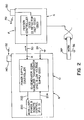
- the solution is illustrated in FIGURES 2-4 .
- the power source connected to the wire feeder is not readily known.
- a mass of comingled power leads from a group of power sources are available for the individual wire feeders.
- the present invention involves communication parameters and conditions from the wire feeder to its power source, it is advantageous to easily determine the particular code of the power source so that the wire feeder can be set to an output code for communication only with the power source connected to the wire feeder.
- the present invention facilitates this advance whereby the feeder knows which power source is generating its power and has a set communication code matching only with that particular power source.
- the associated or connected power source 10 is known.
- the code on transmitter 130 matches the code on receiver 140.
- this code matching procedure is done automatically.
- power source N is connected to a corresponding wire feeder by power lead 50.
- Lead 50 is from a commingled group of leads directed to the welding location of feeder F or N.
- an auxiliary power supply 200 receives control signals in line 202 from the power supply controller of the welder.
- the output of the auxiliary power source is represented as line 204 in the form of transformer 210.
- Transformer 210 has a secondary 212 to create a power supply 214 for transceiver 140.
- transformer 210 has a secondary 220 for creating a low voltage power supply 222 for driving both the identification signal generator 224 and power supply 222.
- an isolated low voltage supply is impressed upon the studs of the power source.
- the low voltage supply provides communication power to the wire feeder. It also is turned on and off by the identification generator forming a serial data stream.
- the data stream conveys the identification number or code that is unique to the power source controller to the wire feeder connected to the power source.
- the wire feeder uses a unique identification number or code from the power source controller to encode RF data sent to the wireless controls of the receiver in the power source.
- the power source controller can also send RF data to the wire feeder once the unique identification of the wire feeder is established.
- a coded signal is transmitted to the wire feeder on power lead 50.
- This coded signal has a voltage of less than about 15-20 volts.
- a coded signal unique to power source N is transmitted through line 50 of this power source.
- This line is connected to wire feeder F which reads the identification code on line 5 0 and sets feeder F to have an output code so the feeder F corresponds in coded communication Language with power source N.
- transmitted signal 132 from transmitter 130 is coded to be accepted only by receiver 140 of a particular power source actually connected to wire feeder F. Consequently, merely by selecting a power lead 50 and connecting the power lead to the end of wire feeder F, the wire feeder is configured to communicate only with the power source N which is the originator of the input lead 50. This is highly advantageous in a shipyard environment where the power leads from the power sources are connected, disconnected and comingled in unidentified patterns.
- transceiver 140 actually uses receiver 240 to receive uniquely coded signal 132 from the wire feeder connected to the power source.
- the transmitter stage 242 is used in practice; however, information is generally not transmitted back to the wire feeder, although this could be done on the basis of the same unique code.
- Transceiver 140 has an output stage or wireless controls that communicate commands to a parameter circuit, such as voltage control circuit 20, or a condition command to control a condition, such as on and off control circuit 22. This has been explained in connection with FIGURE 1 .
- the identification code generator 224 creates a low voltage digital signal 250 represented in FIGURE 7 .
- An output transistor 252 controls the logic signal on power leads 50 by line 258 at the anode of diode 259.
- the emitter of transistor 252 is connected to common ground 24.
- a plurality of pin switches are used as a select device 260 to select the particular or unique code transmitted by generator 224 on power lead 50.
- device 260 sets the same code in receiver 240 as indicated by line 260a.
- power source 10 identified as source N
- This code is transmitted to a wire feeder.
- lead 50(N) is connected to a wire feeder
- the wire feeder identifies the particular power source from which it is receiving its input power. This is used in connection with the system illustrated in FIGURE 1 .
- a common unique code exists in both the wire feeder and the connected power source N.
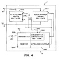
- wire feeder F receives power from leads 50N. This drives the power bridge 230 and directs the coded information to identification detector 232.
- Bridge 232 includes input digital coded information on line 270 and has an output 274 on which the code in the form of a signal is received from the center tap of divider 276.
- the coded signal in line 274 is directed to the identification detection and comparator 280 to set the code for wire feeder F in accordance with the code received on line 50N from the connected power source N-
- the set code is used in the transmitter section 282 of transceiver 130 to produce coded signal L 32 for controlling a parameter and/or a condition of the associated connected power source N.
- Transceiver 130 also has a receiving stage which is not used in practice, but which could be used for receiving coded information from power source N connected to the wire feeder.
- the feeder power bridge rectifier provides power to the feeder and load isolation from digital signals for either electrode polarity.
- the identification detector bridge rectifier provides proper polarization of the signal for either electrode polarity.
- Wireless controls transmit output control information to the power source using the radiofrequency (RF) data encoded with the unique identification number or code received from the power source. Once the unique identification number or code is established, the wire feeder can receive encoded radiofrequency data from the power source, as well, although this is not now used in practice.
- RF radiofrequency
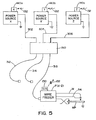
- FIGURE 5 A plurality of power sources, such as power source X, power source Y, power source Z, have output leads 302,304 and 306, respectively. Of course, many more power sources are used in a particular welding network. Leads 302, 304 and 306 are commingled as represented by box 310. The leads are grouped as output leads 312, 314 and 316. There is no way to determine which power source lead is connected to one of the stinger leads 312, 314 and 316. the invention solves this dilemma.
- the lead 316 connected to power source F has a unique coded signal. This coded signal is identified by the wire feeder to set the communication code for transceiver 130.
- the code of signal 132 is set according to the signal on lead 316.
- transmitted signal 132 is set to a code recognized by only the actual power source in the group of power sources.
- This inventive concept is illustrated differently in FIGURE 6 .
- the lead 50 from power source 10 to wire feeder F carries a unique code from transmitter 224.
- This unique code is received and read by decoder 232 so that the signal 132 between transmitter 130 and receiver 140 is coded to the particular unique code of the power source actually connected to the wire feeder.
- the unique power source identification code has a variety of implementations.
- code 250 shown in FIGURE 7 , is a serial digital signal transmitted from a power source. This code is illustrated as being the number 5-2-4.
- a wire feeder When a wire feeder receives the signal 5-2-4 code, it identifies the code and sets its internal transmitter to transmit signals only to the 5-2-4 power source. This process is functionally disclosed in FIGURE 8 .
- the steps for producing the present invention start with the box 320.
- This box indicates that the power source transmits a signal with code N.
- the code N signal is received by the wire feeder and is employed to set the wire feeder to the corresponding code N.
- the information on signal 132 transmitted back to the power source has a carrier with the code N so that only the power source N receives the command and/or operation data on signal 132. Consequently, only the power source N is responsive to the information from wire feeder F.
- a large number ofpower sources can be used with a number of wire feeders.
- the wire feeder By merely connecting a power lead to the wire feeder, the wire feeder is set to communicate only with the power source from which it receives its welding power.
- This identification procedure greatly enhances the invention illustrated in FIGURE 1 wherein the associated wire feeder and power source are connected and communication is by RF or through the power lead so that there is no need for mechanical connectors in the wire feeder itself.
Landscapes
- Engineering & Computer Science (AREA)
- Physics & Mathematics (AREA)
- Plasma & Fusion (AREA)
- Mechanical Engineering (AREA)
- Arc Welding Control (AREA)
Claims (5)
- Netzwerk umfassend eine Drahtvorschubeinrichtung (F) mit einem Schweißstrominput und mehreren Stromquellen (10), von denen jede einen Ausgabeanschluss (50) aufweist, der mit dem Input der Drahtvorschubeinrichtung (F) verbindbar ist, dadurch gekennzeichnet, dass jede der Stromquellen (10) einen Sender aufweist und derart konfiguriert ist, dass ein eindeutiges kodiertes Signal, das für diese eine der Stromquellen (10) an deren Ausgabeanschluss (50) besonders ist, über den Sender übertragen wird, und jede der Stromquellen (10) einen Empfänger (140) aufweist und derart konfiguriert ist, dass kodierte Kommandosignale von der Drahtvorschubeinrichtung (F) empfangen werden, wobei die Drahtvorschubeinrichtung (F) einen Schaltkreis (80) aufweist, zum Dekodieren des einmaligen kodierten Signals, das über den Ausgabeanschluss (50) von der einen (10) der Stromquellen, die mit der Drahtvorschubeinrichtung (F) verbunden sind, empfangen wird, wobei die Drahtvorschubeinrichtung (F) einen Sender (130) aufweist und derart konfiguriert ist, dass kodierte Kommandosignale gesendet werden, die mit dem einmaligen kodierten Signal kodiert sind, um nur durch die eine (10) der mehreren Stromquellen, die mit der Drahtvorschubeinrichtung (F) verbunden sind, empfangen zu werden, zum Betrieb der einen (10) der mehreren Stromquellen gemäß dem Kommandosignal, das von der Drahtvorschubeinrichtung (F) gesendet wird.
- Netzwerk nach Anspruch 1, wobei das Kommandosignal, das von der Drahtvorschubeinrichtung gesendet wird, ein kodiertes Signal mit einem Code ist, der für die verbundene Stromquelle einmalig ist.
- Netzwerk nach einem der Ansprüche 1 oder 2, wobei das kodierte Signal durch einen Schalter erzeugt wird, der in Antwort auf das Schließen des Schweißauslösers einer Pistole betätigt wird, die durch die Drahtvorschubeinrichtung betätigt wird.
- Netzwerk nach einem der Ansprüche 1 bis 3, wobei das Kommandosignal, das von der Drahtvorschubeinrichtung gesendet wird, eine Spannung ist, die über einen Knopf auf der Drahtvorschubeinrichtung ausgewählt wird.
- Netzwerk nach einem der Ansprüche 1 bis 3, wobei das Kommandosignal, das von der Drahtvorschubeinrichtung gesendet wird, eine kodierte Spannung ist, die durch einen Schaltkreis, der auf einen Knopf auf der Drahtvorschubeinrichtung reagiert, erzeugt wird.
Applications Claiming Priority (2)
| Application Number | Priority Date | Filing Date | Title |
|---|---|---|---|
| US10/800,211 US7294808B2 (en) | 2004-03-15 | 2004-03-15 | Remote wire feeder |
| PCT/US2004/026680 WO2005094213A2 (en) | 2004-03-15 | 2004-08-18 | Remote wire feeder |
Publications (3)
| Publication Number | Publication Date |
|---|---|
| EP1725367A2 EP1725367A2 (de) | 2006-11-29 |
| EP1725367A4 EP1725367A4 (de) | 2009-08-26 |
| EP1725367B1 true EP1725367B1 (de) | 2014-10-15 |
Family
ID=34920669
Family Applications (1)
| Application Number | Title | Priority Date | Filing Date |
|---|---|---|---|
| EP04781385.2A Expired - Lifetime EP1725367B1 (de) | 2004-03-15 | 2004-08-18 | Netzrahmung mit fern-drahtzuführung und mehreren leistungsquellen |
Country Status (7)
| Country | Link |
|---|---|
| US (1) | US7294808B2 (de) |
| EP (1) | EP1725367B1 (de) |
| CN (1) | CN101421070B (de) |
| AU (1) | AU2004317874B2 (de) |
| CA (1) | CA2533778C (de) |
| MX (1) | MXPA06002225A (de) |
| WO (1) | WO2005094213A2 (de) |
Families Citing this family (65)
| Publication number | Priority date | Publication date | Assignee | Title |
|---|---|---|---|---|
| US7205503B2 (en) | 2003-07-24 | 2007-04-17 | Illinois Tool Works Inc. | Remotely controlled welding machine |
| US9012807B2 (en) * | 2004-04-16 | 2015-04-21 | Illinois Tool Works Inc. | Remote wire feeder using binary phase shift keying to modulate communications of command/control signals to be transmitted over a weld cable |
| US7180029B2 (en) * | 2004-04-16 | 2007-02-20 | Illinois Tool Works Inc. | Method and system for a remote wire feeder where standby power and system control are provided via weld cables |
| US8592724B2 (en) * | 2004-04-16 | 2013-11-26 | Illinois Tool Works Inc. | Remote wire feeder using binary phase shift keying to modulate communications of command/control signals to be transmitted over a weld cable |
| US8431862B2 (en) | 2005-08-25 | 2013-04-30 | Lincoln Global, Inc. | Torch for electric arc welding system |
| US10144080B2 (en) | 2005-08-25 | 2018-12-04 | Lincoln Global, Inc. | Torch for electric arc welding or plasma cutting system |
| US8658941B2 (en) * | 2006-09-07 | 2014-02-25 | Illinois Tool Works Inc. | Wireless system control and inventory monitoring for welding-type devices |
| US9180544B2 (en) * | 2006-11-16 | 2015-11-10 | Illinois Tool Works Inc. | Method and apparatus for wireless remote control communication of a welder |
| US8937265B2 (en) * | 2007-02-27 | 2015-01-20 | Illinois Tool Works, Inc. | Welding-type system having a wire feeder system having integrated power source controls and a welding-type power source that is free power parameter selection interfaces |
| WO2009059186A1 (en) * | 2007-10-31 | 2009-05-07 | Primaeva Medical, Inc. | Cartridge electrode device |
| US20090156958A1 (en) * | 2007-12-12 | 2009-06-18 | Mehta Bankim H | Devices and methods for percutaneous energy delivery |
| US8803033B2 (en) | 2008-10-22 | 2014-08-12 | Lincoln Global, Inc. | Semi-automatic brazing device |
| US8592722B2 (en) | 2008-11-03 | 2013-11-26 | Illinois Tool Works Inc. | Weld parameter interface |
| US8803031B2 (en) * | 2009-06-02 | 2014-08-12 | Lincoln Global, Inc. | Wire feeder with auto-configure power supply |
| US8330077B2 (en) | 2009-09-03 | 2012-12-11 | Illinois Tool Works Inc. | Remote welding system and method |
| US8957344B2 (en) * | 2009-09-30 | 2015-02-17 | Illinois Tool Works Inc. | Welding system with power line communication |
| US20110220616A1 (en) * | 2010-03-10 | 2011-09-15 | Illinois Tool Works Inc. | Welding device with integral user interface |
| US9545687B2 (en) * | 2010-12-17 | 2017-01-17 | Hobart Brothers Company | Spool gun adapter |
| CN102172793A (zh) * | 2011-02-17 | 2011-09-07 | 苏州日月明微电子科技有限公司 | 焊线机的物料感应器 |
| CA2837385A1 (en) | 2011-05-26 | 2012-11-29 | Thermal Dynamics Corporation | Improved initiation of welding arc by restricting output |
| CN103747912B (zh) * | 2011-05-26 | 2016-08-17 | 维克托设备公司 | 产生焊接的系统及利用基于计算的焊接输出功率的电压和送丝速度的修正控制焊机的方法 |
| US10328514B2 (en) * | 2011-11-07 | 2019-06-25 | Lincoln Global, Inc. | Use of mobile communications devices as user interface for welding equipment and systems |
| US20190240761A1 (en) * | 2011-11-07 | 2019-08-08 | Lincoln Global, Inc. | Use of mobile communication devices as user interface for welding equipment and systems |
| US20130119037A1 (en) * | 2011-11-11 | 2013-05-16 | Lincoln Global, Inc. | Systems and methods for utilizing welder power source data |
| JP5871373B2 (ja) * | 2012-01-12 | 2016-03-01 | 株式会社ダイヘン | アーク溶接装置 |
| US20130200055A1 (en) | 2012-02-02 | 2013-08-08 | Lincoln Global, Inc. | Power source and wire feeder matching |
| US10507542B2 (en) * | 2012-05-31 | 2019-12-17 | Illinois Tool Works Inc. | System and method for pairing welding devices |
| US9878393B2 (en) | 2012-06-08 | 2018-01-30 | Illinois Tool Works Inc. | Welding wire feeder power control system and method |
| US9662735B2 (en) | 2012-06-08 | 2017-05-30 | Illinois Tool Works Inc. | Welding wire feeder power application system and method |
| US10406621B2 (en) | 2012-06-08 | 2019-09-10 | Illinois Tool Works Inc. | Polarity sensing welding wire feeder system and method |
| US9463523B2 (en) | 2012-06-08 | 2016-10-11 | Illinois Tool Works Inc. | Controlled waveform welding wire feeder system and method |
| US10384289B2 (en) | 2012-06-08 | 2019-08-20 | Illinois Tool Works Inc. | Welding wire feeder bus control system and method |
| US10105781B2 (en) | 2012-06-08 | 2018-10-23 | Illinois Tool Works Inc. | Welding system inrush current control system and method |
| US20140001169A1 (en) * | 2012-06-28 | 2014-01-02 | Lincoln Global, Inc. | Two-way communication between a wire feeder and a welding power source providing improved operation |
| US10213861B2 (en) * | 2013-03-11 | 2019-02-26 | Illinois Tool Works Inc. | Automated system for machine set-up of welding power sources and welding systems |
| US10076809B2 (en) * | 2013-03-13 | 2018-09-18 | Illinois Tool Works Inc. | Voltage sensing wire feeder with weld procedure memories |
| DE102014104227B4 (de) | 2014-03-26 | 2016-08-18 | Lorch Schweißtechnik GmbH | VERFAHREN ZUR FUNKTIONSERWEITERUNG EINES ELEKTRISCHEN SCHWEIßGERÄTS UND SCHWEIßGERÄT ZUR DURCHFÜHRUNG DES VERFAHRENS |
| JP6424026B2 (ja) * | 2014-07-01 | 2018-11-14 | 株式会社ダイヘン | 溶接システム |
| JP6424038B2 (ja) * | 2014-07-25 | 2018-11-14 | 株式会社ダイヘン | 溶接装置、および、加工システム |
| US20160175972A1 (en) * | 2014-12-18 | 2016-06-23 | Illinois Tool Works Inc. | Systems and methods for providing a welding system access to a network via power lines |
| US20160193681A1 (en) * | 2015-01-07 | 2016-07-07 | Illinois Tool Works Inc. | Synchronized image capture for welding machine vision |
| US10773329B2 (en) | 2015-01-20 | 2020-09-15 | Illinois Tool Works Inc. | Multiple input welding vision system |
| US10448692B2 (en) | 2015-03-06 | 2019-10-22 | Illinois Tool Works Inc. | Sensor assisted head mounted displays for welding |
| CN107980153B (zh) | 2015-03-09 | 2021-10-22 | 伊利诺斯工具制品有限公司 | 提供与焊接操作相关联的视觉信息的方法和装置 |
| US9977242B2 (en) | 2015-03-26 | 2018-05-22 | Illinois Tool Works Inc. | Control of mediated reality welding system based on lighting conditions |
| US20160311046A1 (en) * | 2015-04-26 | 2016-10-27 | Antonio Aguilar | Wireless control of a welding machine |
| US10363632B2 (en) | 2015-06-24 | 2019-07-30 | Illinois Tool Works Inc. | Time of flight camera for welding machine vision |
| US10369652B2 (en) | 2015-07-24 | 2019-08-06 | Illinois Tool Works Inc. | Wireless and powerline communications in a welding-type system |
| US11491573B2 (en) | 2015-08-17 | 2022-11-08 | Illinois Tool Works Inc. | Portable advanced process module |
| CN105772907B (zh) * | 2016-05-10 | 2017-06-06 | 成都熊谷加世电器有限公司 | 一种管道内焊机电器控制系统 |
| US10532417B2 (en) | 2016-08-08 | 2020-01-14 | Lincoln Global, Inc. | Dual battery hybrid engine drive welding power supply |
| US11213907B2 (en) * | 2017-01-04 | 2022-01-04 | Illinois Tool Works Inc. | Methods and systems for selecting welding schedules in a welding-type torch |
| US11185941B2 (en) | 2017-03-02 | 2021-11-30 | Illinois Tool Works Inc. | Welding-type devices having configurable interfaces |
| US10710191B2 (en) * | 2017-03-31 | 2020-07-14 | Illinois Tool Works Inc. | Retractable work cable |
| US10906115B2 (en) | 2017-11-16 | 2021-02-02 | Illinois Tool Works Inc. | Automatic process and/or set up of welding type system |
| CN109967660A (zh) * | 2017-12-27 | 2019-07-05 | 核工业西南物理研究院 | 一种自动切割电热丝的装置 |
| EP3511103A1 (de) * | 2018-01-11 | 2019-07-17 | FRONIUS INTERNATIONAL GmbH | Drahtformungseinheit und schweissbrenner mit drahtformungseinheit |
| US11450233B2 (en) | 2019-02-19 | 2022-09-20 | Illinois Tool Works Inc. | Systems for simulating joining operations using mobile devices |
| US11817006B2 (en) | 2019-02-19 | 2023-11-14 | Ilinois Tool Works Inc. Assignee | Weld modules for weld training systems |
| US11521512B2 (en) | 2019-02-19 | 2022-12-06 | Illinois Tool Works Inc. | Systems for simulating joining operations using mobile devices |
| US12220774B2 (en) * | 2019-10-22 | 2025-02-11 | Illinois Tool Works Inc. | Systems and methods for multiple source control of an engine driven power system |
| US11721231B2 (en) | 2019-11-25 | 2023-08-08 | Illinois Tool Works Inc. | Weld training simulations using mobile devices, modular workpieces, and simulated welding equipment |
| US12198568B2 (en) | 2019-11-25 | 2025-01-14 | Illinois Tool Works Inc. | Weld training simulations using mobile devices, modular workpieces, and simulated welding equipment |
| US11322037B2 (en) | 2019-11-25 | 2022-05-03 | Illinois Tool Works Inc. | Weld training simulations using mobile devices, modular workpieces, and simulated welding equipment |
| MX2022000588A (es) | 2021-01-15 | 2022-11-07 | Illinois Tool Works | Sistemas y metodos para seleccionar parámetros de soldadura con base en propiedades termicas, electricas y/o quimicas. |
Family Cites Families (9)
| Publication number | Priority date | Publication date | Assignee | Title |
|---|---|---|---|---|
| US4147919A (en) * | 1977-01-24 | 1979-04-03 | Matasovic John L | Remote control portable wirefeed arc welding system |
| KR100287179B1 (ko) * | 1998-09-04 | 2001-04-16 | 윤종용 | 비트라인를포함하는반도체장치및그제조방법 |
| JP3287335B2 (ja) * | 1999-05-25 | 2002-06-04 | 松下電器産業株式会社 | アーク溶接電源とアーク溶接用周辺機器とアーク溶接装置 |
| US6204479B1 (en) * | 1999-08-13 | 2001-03-20 | Illinois Tool Works Inc. | Thermistor protection for a wire feed motor |
| US6291798B1 (en) * | 1999-09-27 | 2001-09-18 | Lincoln Global, Inc. | Electric ARC welder with a plurality of power supplies |
| FR2803233B1 (fr) | 2000-01-03 | 2002-03-29 | Air Liquide | Dispositif de commande a distance sans fil d'une installation de travail a l'arc electrique |
| AT412389B (de) * | 2000-12-11 | 2005-02-25 | Fronius Int Gmbh | System zur durchführung eines schweissprozesses |
| US6670579B2 (en) | 2001-09-19 | 2003-12-30 | Illinois Tool Works Inc. | Welding-type system with network and multiple level messaging between components |
| US20050252898A1 (en) * | 2002-07-04 | 2005-11-17 | Kurt Blechinger | Method for operating a welding device, and one such welding device |
-
2004
- 2004-03-15 US US10/800,211 patent/US7294808B2/en not_active Expired - Lifetime
- 2004-08-18 CN CN200480028012XA patent/CN101421070B/zh not_active Expired - Fee Related
- 2004-08-18 WO PCT/US2004/026680 patent/WO2005094213A2/en not_active Ceased
- 2004-08-18 CA CA2533778A patent/CA2533778C/en not_active Expired - Fee Related
- 2004-08-18 EP EP04781385.2A patent/EP1725367B1/de not_active Expired - Lifetime
- 2004-08-18 MX MXPA06002225A patent/MXPA06002225A/es active IP Right Grant
- 2004-08-18 AU AU2004317874A patent/AU2004317874B2/en not_active Ceased
Also Published As
| Publication number | Publication date |
|---|---|
| CN101421070B (zh) | 2012-02-08 |
| EP1725367A2 (de) | 2006-11-29 |
| WO2005094213A2 (en) | 2005-10-13 |
| AU2004317874A1 (en) | 2005-10-13 |
| CN101421070A (zh) | 2009-04-29 |
| EP1725367A4 (de) | 2009-08-26 |
| MXPA06002225A (es) | 2006-05-17 |
| US7294808B2 (en) | 2007-11-13 |
| US20050199605A1 (en) | 2005-09-15 |
| AU2004317874B2 (en) | 2008-03-13 |
| CA2533778C (en) | 2010-11-09 |
| CA2533778A1 (en) | 2005-10-13 |
| WO2005094213A3 (en) | 2009-04-23 |
Similar Documents
| Publication | Publication Date | Title |
|---|---|---|
| EP1725367B1 (de) | Netzrahmung mit fern-drahtzuführung und mehreren leistungsquellen | |
| US6906285B2 (en) | Remote wire feeder | |
| CN102639275B (zh) | 具有用于提供电力和交换数据的辅助电传动导管的焊接系统 | |
| US7381922B2 (en) | Method and apparatus for remotely controlling a welding system | |
| CN102596477B (zh) | 远程焊接系统及悬架式操纵台 | |
| CN101516561B (zh) | 用于焊接机的无线远程控制通信的方法和装置 | |
| US11007610B2 (en) | Voltage sensing wire feeder with weld procedure memories | |
| EP1586403B1 (de) | Schweissanlage mit einer Schweissdrahtzuführvorrichtung wobei die Bereitschafts-Stromversorgung über die Schweisskabel erfolgt | |
| US7205503B2 (en) | Remotely controlled welding machine | |
| CN101360580A (zh) | 使用双相移相键控来沿焊接电缆传送指令并通过焊接电缆与电源和远程设备相连的焊接型系统,使用这种传送移相键控来远程控制这种电源的方法 | |
| US20150328710A1 (en) | Torch for electric arc welding system | |
| CN110788445A (zh) | 用于焊接机的无线遥控通信的方法和装置 | |
| KR101073745B1 (ko) | 용접기 장치 및 그 제어방법 | |
| US20160311046A1 (en) | Wireless control of a welding machine | |
| US20230398622A1 (en) | Systems and methods for weld process selection and isolation from a voltage sensing wire feeder | |
| KR102502690B1 (ko) | 초기조건 및 크레이터 용접모드를 가지는 용접장치 | |
| KR101665323B1 (ko) | 용접기의 제어장치 | |
| CA2472064C (en) | Safety isolation of arc welding equipment | |
| JP2016209892A (ja) | 溶接システム、溶接電源装置、および、それらの送給制御方法 | |
| KR101571535B1 (ko) | 디지털/아날로그 송급장치 자동제어기 및 이를 이용한 제어방법 | |
| JPH0556235B2 (de) | ||
| AU2004202884B2 (en) | Safety Isolation of Arc Welding Equipment |
Legal Events
| Date | Code | Title | Description |
|---|---|---|---|
| PUAI | Public reference made under article 153(3) epc to a published international application that has entered the european phase |
Free format text: ORIGINAL CODE: 0009012 |
|
| 17P | Request for examination filed |
Effective date: 20060410 |
|
| AK | Designated contracting states |
Kind code of ref document: A2 Designated state(s): AT BE BG CH CY CZ DE DK EE ES FI FR GB GR HU IE IT LI LU MC NL PL PT RO SE SI SK TR |
|
| AX | Request for extension of the european patent |
Extension state: AL HR LT LV MK |
|
| RIN1 | Information on inventor provided before grant (corrected) |
Inventor name: CLARK, KEITH, L. Inventor name: FURMAN, EDWARD, M. |
|
| DAX | Request for extension of the european patent (deleted) | ||
| RAP1 | Party data changed (applicant data changed or rights of an application transferred) |
Owner name: LINCOLN GLOBAL, INC. |
|
| PUAK | Availability of information related to the publication of the international search report |
Free format text: ORIGINAL CODE: 0009015 |
|
| A4 | Supplementary search report drawn up and despatched |
Effective date: 20090724 |
|
| RIC1 | Information provided on ipc code assigned before grant |
Ipc: B23K 9/133 20060101ALI20090720BHEP Ipc: B23K 9/095 20060101ALI20090720BHEP Ipc: B23K 9/10 20060101AFI20060518BHEP Ipc: B23K 9/12 20060101ALI20090720BHEP |
|
| 17Q | First examination report despatched |
Effective date: 20091111 |
|
| GRAP | Despatch of communication of intention to grant a patent |
Free format text: ORIGINAL CODE: EPIDOSNIGR1 |
|
| INTG | Intention to grant announced |
Effective date: 20140528 |
|
| GRAS | Grant fee paid |
Free format text: ORIGINAL CODE: EPIDOSNIGR3 |
|
| GRAA | (expected) grant |
Free format text: ORIGINAL CODE: 0009210 |
|
| AK | Designated contracting states |
Kind code of ref document: B1 Designated state(s): AT BE BG CH CY CZ DE DK EE ES FI FR GB GR HU IE IT LI LU MC NL PL PT RO SE SI SK TR |
|
| REG | Reference to a national code |
Ref country code: GB Ref legal event code: FG4D Ref country code: CH Ref legal event code: EP |
|
| REG | Reference to a national code |
Ref country code: DE Ref legal event code: R081 Ref document number: 602004046011 Country of ref document: DE Owner name: LINCOLN GLOBAL, INC., SANTA FE SPRINGS, US Free format text: FORMER OWNER: LINCOLN GLOBAL, INC., SANTA FE SPRINGS, CALIF., US |
|
| REG | Reference to a national code |
Ref country code: IE Ref legal event code: FG4D |
|
| REG | Reference to a national code |
Ref country code: AT Ref legal event code: REF Ref document number: 691404 Country of ref document: AT Kind code of ref document: T Effective date: 20141115 |
|
| REG | Reference to a national code |
Ref country code: DE Ref legal event code: R096 Ref document number: 602004046011 Country of ref document: DE Effective date: 20141120 |
|
| REG | Reference to a national code |
Ref country code: NL Ref legal event code: VDEP Effective date: 20141015 |
|
| REG | Reference to a national code |
Ref country code: AT Ref legal event code: MK05 Ref document number: 691404 Country of ref document: AT Kind code of ref document: T Effective date: 20141015 |
|
| PG25 | Lapsed in a contracting state [announced via postgrant information from national office to epo] |
Ref country code: NL Free format text: LAPSE BECAUSE OF FAILURE TO SUBMIT A TRANSLATION OF THE DESCRIPTION OR TO PAY THE FEE WITHIN THE PRESCRIBED TIME-LIMIT Effective date: 20141015 |
|
| PG25 | Lapsed in a contracting state [announced via postgrant information from national office to epo] |
Ref country code: ES Free format text: LAPSE BECAUSE OF FAILURE TO SUBMIT A TRANSLATION OF THE DESCRIPTION OR TO PAY THE FEE WITHIN THE PRESCRIBED TIME-LIMIT Effective date: 20141015 Ref country code: FI Free format text: LAPSE BECAUSE OF FAILURE TO SUBMIT A TRANSLATION OF THE DESCRIPTION OR TO PAY THE FEE WITHIN THE PRESCRIBED TIME-LIMIT Effective date: 20141015 Ref country code: PT Free format text: LAPSE BECAUSE OF FAILURE TO SUBMIT A TRANSLATION OF THE DESCRIPTION OR TO PAY THE FEE WITHIN THE PRESCRIBED TIME-LIMIT Effective date: 20150216 |
|
| PG25 | Lapsed in a contracting state [announced via postgrant information from national office to epo] |
Ref country code: PL Free format text: LAPSE BECAUSE OF FAILURE TO SUBMIT A TRANSLATION OF THE DESCRIPTION OR TO PAY THE FEE WITHIN THE PRESCRIBED TIME-LIMIT Effective date: 20141015 Ref country code: GR Free format text: LAPSE BECAUSE OF FAILURE TO SUBMIT A TRANSLATION OF THE DESCRIPTION OR TO PAY THE FEE WITHIN THE PRESCRIBED TIME-LIMIT Effective date: 20150116 Ref country code: CY Free format text: LAPSE BECAUSE OF FAILURE TO SUBMIT A TRANSLATION OF THE DESCRIPTION OR TO PAY THE FEE WITHIN THE PRESCRIBED TIME-LIMIT Effective date: 20141015 Ref country code: AT Free format text: LAPSE BECAUSE OF FAILURE TO SUBMIT A TRANSLATION OF THE DESCRIPTION OR TO PAY THE FEE WITHIN THE PRESCRIBED TIME-LIMIT Effective date: 20141015 Ref country code: SE Free format text: LAPSE BECAUSE OF FAILURE TO SUBMIT A TRANSLATION OF THE DESCRIPTION OR TO PAY THE FEE WITHIN THE PRESCRIBED TIME-LIMIT Effective date: 20141015 |
|
| REG | Reference to a national code |
Ref country code: DE Ref legal event code: R097 Ref document number: 602004046011 Country of ref document: DE |
|
| PG25 | Lapsed in a contracting state [announced via postgrant information from national office to epo] |
Ref country code: SK Free format text: LAPSE BECAUSE OF FAILURE TO SUBMIT A TRANSLATION OF THE DESCRIPTION OR TO PAY THE FEE WITHIN THE PRESCRIBED TIME-LIMIT Effective date: 20141015 Ref country code: RO Free format text: LAPSE BECAUSE OF FAILURE TO SUBMIT A TRANSLATION OF THE DESCRIPTION OR TO PAY THE FEE WITHIN THE PRESCRIBED TIME-LIMIT Effective date: 20141015 Ref country code: CZ Free format text: LAPSE BECAUSE OF FAILURE TO SUBMIT A TRANSLATION OF THE DESCRIPTION OR TO PAY THE FEE WITHIN THE PRESCRIBED TIME-LIMIT Effective date: 20141015 Ref country code: EE Free format text: LAPSE BECAUSE OF FAILURE TO SUBMIT A TRANSLATION OF THE DESCRIPTION OR TO PAY THE FEE WITHIN THE PRESCRIBED TIME-LIMIT Effective date: 20141015 Ref country code: DK Free format text: LAPSE BECAUSE OF FAILURE TO SUBMIT A TRANSLATION OF THE DESCRIPTION OR TO PAY THE FEE WITHIN THE PRESCRIBED TIME-LIMIT Effective date: 20141015 |
|
| PLBE | No opposition filed within time limit |
Free format text: ORIGINAL CODE: 0009261 |
|
| STAA | Information on the status of an ep patent application or granted ep patent |
Free format text: STATUS: NO OPPOSITION FILED WITHIN TIME LIMIT |
|
| PG25 | Lapsed in a contracting state [announced via postgrant information from national office to epo] |
Ref country code: IT Free format text: LAPSE BECAUSE OF FAILURE TO SUBMIT A TRANSLATION OF THE DESCRIPTION OR TO PAY THE FEE WITHIN THE PRESCRIBED TIME-LIMIT Effective date: 20141015 |
|
| 26N | No opposition filed |
Effective date: 20150716 |
|
| PG25 | Lapsed in a contracting state [announced via postgrant information from national office to epo] |
Ref country code: SI Free format text: LAPSE BECAUSE OF FAILURE TO SUBMIT A TRANSLATION OF THE DESCRIPTION OR TO PAY THE FEE WITHIN THE PRESCRIBED TIME-LIMIT Effective date: 20141015 |
|
| PG25 | Lapsed in a contracting state [announced via postgrant information from national office to epo] |
Ref country code: MC Free format text: LAPSE BECAUSE OF FAILURE TO SUBMIT A TRANSLATION OF THE DESCRIPTION OR TO PAY THE FEE WITHIN THE PRESCRIBED TIME-LIMIT Effective date: 20141015 Ref country code: LU Free format text: LAPSE BECAUSE OF FAILURE TO SUBMIT A TRANSLATION OF THE DESCRIPTION OR TO PAY THE FEE WITHIN THE PRESCRIBED TIME-LIMIT Effective date: 20150818 |
|
| REG | Reference to a national code |
Ref country code: CH Ref legal event code: PL |
|
| GBPC | Gb: european patent ceased through non-payment of renewal fee |
Effective date: 20150818 |
|
| PG25 | Lapsed in a contracting state [announced via postgrant information from national office to epo] |
Ref country code: LI Free format text: LAPSE BECAUSE OF NON-PAYMENT OF DUE FEES Effective date: 20150831 Ref country code: CH Free format text: LAPSE BECAUSE OF NON-PAYMENT OF DUE FEES Effective date: 20150831 |
|
| REG | Reference to a national code |
Ref country code: IE Ref legal event code: MM4A |
|
| REG | Reference to a national code |
Ref country code: FR Ref legal event code: ST Effective date: 20160429 |
|
| PG25 | Lapsed in a contracting state [announced via postgrant information from national office to epo] |
Ref country code: IE Free format text: LAPSE BECAUSE OF NON-PAYMENT OF DUE FEES Effective date: 20150818 Ref country code: GB Free format text: LAPSE BECAUSE OF NON-PAYMENT OF DUE FEES Effective date: 20150818 |
|
| PG25 | Lapsed in a contracting state [announced via postgrant information from national office to epo] |
Ref country code: FR Free format text: LAPSE BECAUSE OF NON-PAYMENT OF DUE FEES Effective date: 20150831 |
|
| PG25 | Lapsed in a contracting state [announced via postgrant information from national office to epo] |
Ref country code: HU Free format text: LAPSE BECAUSE OF FAILURE TO SUBMIT A TRANSLATION OF THE DESCRIPTION OR TO PAY THE FEE WITHIN THE PRESCRIBED TIME-LIMIT; INVALID AB INITIO Effective date: 20040818 Ref country code: BG Free format text: LAPSE BECAUSE OF FAILURE TO SUBMIT A TRANSLATION OF THE DESCRIPTION OR TO PAY THE FEE WITHIN THE PRESCRIBED TIME-LIMIT Effective date: 20141015 |
|
| PG25 | Lapsed in a contracting state [announced via postgrant information from national office to epo] |
Ref country code: TR Free format text: LAPSE BECAUSE OF FAILURE TO SUBMIT A TRANSLATION OF THE DESCRIPTION OR TO PAY THE FEE WITHIN THE PRESCRIBED TIME-LIMIT Effective date: 20141015 |
|
| PG25 | Lapsed in a contracting state [announced via postgrant information from national office to epo] |
Ref country code: BE Free format text: LAPSE BECAUSE OF FAILURE TO SUBMIT A TRANSLATION OF THE DESCRIPTION OR TO PAY THE FEE WITHIN THE PRESCRIBED TIME-LIMIT Effective date: 20141015 |
|
| REG | Reference to a national code |
Ref country code: DE Ref legal event code: R082 Ref document number: 602004046011 Country of ref document: DE Representative=s name: GROSSE, SCHUMACHER, KNAUER, VON HIRSCHHAUSEN, DE Ref country code: DE Ref legal event code: R081 Ref document number: 602004046011 Country of ref document: DE Owner name: LINCOLN GLOBAL, INC., SANTA FE SPRINGS, US Free format text: FORMER OWNER: LINCOLN GLOBAL, INC., CITY OF INDUSTRY, CALIF., US |
|
| PGFP | Annual fee paid to national office [announced via postgrant information from national office to epo] |
Ref country code: DE Payment date: 20210819 Year of fee payment: 18 |
|
| REG | Reference to a national code |
Ref country code: DE Ref legal event code: R119 Ref document number: 602004046011 Country of ref document: DE |
|
| PG25 | Lapsed in a contracting state [announced via postgrant information from national office to epo] |
Ref country code: DE Free format text: LAPSE BECAUSE OF NON-PAYMENT OF DUE FEES Effective date: 20230301 |