EP1724601B1 - Positionierungsvorrichtung und Positionierungsverfahren - Google Patents
Positionierungsvorrichtung und Positionierungsverfahren Download PDFInfo
- Publication number
- EP1724601B1 EP1724601B1 EP06008665A EP06008665A EP1724601B1 EP 1724601 B1 EP1724601 B1 EP 1724601B1 EP 06008665 A EP06008665 A EP 06008665A EP 06008665 A EP06008665 A EP 06008665A EP 1724601 B1 EP1724601 B1 EP 1724601B1
- Authority
- EP
- European Patent Office
- Prior art keywords
- positioning
- code
- codes
- standard code
- analysis assistance
- Prior art date
- Legal status (The legal status is an assumption and is not a legal conclusion. Google has not performed a legal analysis and makes no representation as to the accuracy of the status listed.)
- Ceased
Links
- 238000000034 method Methods 0.000 title claims description 11
- 238000005070 sampling Methods 0.000 description 11
- 230000005540 biological transmission Effects 0.000 description 7
- 230000010354 integration Effects 0.000 description 4
- 238000004891 communication Methods 0.000 description 3
- 230000000875 corresponding effect Effects 0.000 description 3
- 238000000926 separation method Methods 0.000 description 3
- 230000015556 catabolic process Effects 0.000 description 2
- 230000002596 correlated effect Effects 0.000 description 2
- 238000006731 degradation reaction Methods 0.000 description 2
- 230000001934 delay Effects 0.000 description 2
- 238000013461 design Methods 0.000 description 2
- 238000012545 processing Methods 0.000 description 2
- 230000003595 spectral effect Effects 0.000 description 2
- 230000002860 competitive effect Effects 0.000 description 1
- 230000001276 controlling effect Effects 0.000 description 1
- 238000001514 detection method Methods 0.000 description 1
- 238000010790 dilution Methods 0.000 description 1
- 239000012895 dilution Substances 0.000 description 1
- 238000000605 extraction Methods 0.000 description 1
- 230000004807 localization Effects 0.000 description 1
- 230000007774 longterm Effects 0.000 description 1
- 238000005259 measurement Methods 0.000 description 1
- 238000001228 spectrum Methods 0.000 description 1
Images




Classifications
-
- G—PHYSICS
- G01—MEASURING; TESTING
- G01S—RADIO DIRECTION-FINDING; RADIO NAVIGATION; DETERMINING DISTANCE OR VELOCITY BY USE OF RADIO WAVES; LOCATING OR PRESENCE-DETECTING BY USE OF THE REFLECTION OR RERADIATION OF RADIO WAVES; ANALOGOUS ARRANGEMENTS USING OTHER WAVES
- G01S19/00—Satellite radio beacon positioning systems; Determining position, velocity or attitude using signals transmitted by such systems
- G01S19/01—Satellite radio beacon positioning systems transmitting time-stamped messages, e.g. GPS [Global Positioning System], GLONASS [Global Orbiting Navigation Satellite System] or GALILEO
- G01S19/13—Receivers
- G01S19/24—Acquisition or tracking or demodulation of signals transmitted by the system
- G01S19/30—Acquisition or tracking or demodulation of signals transmitted by the system code related
-
- G—PHYSICS
- G01—MEASURING; TESTING
- G01S—RADIO DIRECTION-FINDING; RADIO NAVIGATION; DETERMINING DISTANCE OR VELOCITY BY USE OF RADIO WAVES; LOCATING OR PRESENCE-DETECTING BY USE OF THE REFLECTION OR RERADIATION OF RADIO WAVES; ANALOGOUS ARRANGEMENTS USING OTHER WAVES
- G01S5/00—Position-fixing by co-ordinating two or more direction or position line determinations; Position-fixing by co-ordinating two or more distance determinations
- G01S5/02—Position-fixing by co-ordinating two or more direction or position line determinations; Position-fixing by co-ordinating two or more distance determinations using radio waves
- G01S5/14—Determining absolute distances from a plurality of spaced points of known location
-
- H—ELECTRICITY
- H03—ELECTRONIC CIRCUITRY
- H03M—CODING; DECODING; CODE CONVERSION IN GENERAL
- H03M1/00—Analogue/digital conversion; Digital/analogue conversion
- H03M1/12—Analogue/digital converters
Definitions
- the present invention relates to a positioning apparatus and a positioning method which use positioning standard codes from positioning satellites.
- GPS Global Positioning System
- Such GPS receiver receives a C/A (Clear and Acquisition or Coarse and Access) code, which is one of the pseudo randomnoise codes (hereinafter, referredtoasPN (Pseudo random Noise code)) putted on radio waves from GPS satellites (hereinafter, referred to as satellite radio waves), based on satellite information indicating a GPS satellite orbit (rough satellite orbit information: almanac, accurate orbit information: ephemeris).
- the C/A code is a code serving as a positioning standard.
- the GPS receiver then identifies which GPS satellite transmits the C/A code, and calculates the distance (pseudo distance) between the GPS satellite and the GPS receiver based on the time at which the C/A code is transmitted and the time at which it is received.
- the GPS receiver then positions the position of the GPS receiver based on the pseudo distance of three or more of GPS satellites and the position of each GPS satellite on the satellite orbit (e.g., JP-A-10-339772 ).
- the GPS receiver receives C/A codes from the identical GPS satellite multiple times, and then integrates the sampling results of the C/A codes, thereby improving the SNR.
- integration of the sampling results is simply referred to as integration.
- integration of codes and integration of the sampling results of codes are identical actions.
- US 6,292,748 B1 discloses a method for minimizing time error that uses a drift-susceptible time clock at the receiver carried by an asset to be tracked in a high-accuracy reduced-order GPS asset localization system.
- Long-term accuracy of the time clock is maintained by periodically re-synchronizing the clock with the master GPS time clock so that absolute asset time clock errors are kept below a known limit over the wide temperature ranges expected in the asset tracking application. This is accomplished with only a short GPS signal reception time; i.e., GPS frame synchronization and time-stamp decoding are not needed, and the asset position ambiguity associated with using GPS data-bit or code-bit edges as signal time references is eliminated.
- US 5,610,984 discloses an optimal design of the SPS Receiver.
- the optimal SPS Receiver includes the digital filter with adjustable characteristics in each digital processing channel.
- the optimal design of the SPS Receiver is achieved by adjusting the filter characteristics of each digital filter to match the observed spectrum of the unknown W code satellite signals.
- the matching operation can be performed for each satellite channel with its own secret W code signal.
- WO-A-2004/086077 discloses a method and apparatus for performing signal correlation.
- portions of a pseudorandom reference code are multiplied with portions of a repeating code of the digital signal to produce a plurality of inner products.
- the plurality of inner products are then integrated over a period less than a period of the repeating code to produce a corrlelation result with a broadened frequency response.
- the digital signal is correlated with a pseudorandom reference code toproduce a first correlation.
- the first and second correlations are then used to determine first and second signal delays.
- the frequency shift of the digital signal is computed using a difference between the first and second signal delays over time.
- a positioning apparatus for receiving a positioning standard code which is used as a standard of positioning from a positioning satellite, comprising: analysis assistance code generating means for generating a plurality of analysis assistance codes comprising replicas of a received positioning standard code for use in determining which positioning satellite corresponds to the received positioning standard code; positioning standard code identifying means for analyzing the positioning standard code and the analysis assistance codes, and identifying which positioning satellite corresponds to the positioning standard code, the positioning standard code identifying means comprising: means for integrating the received positioning standard code and the plurality of generated analysis assistance codes to generate an integrated result, and means for correlating the integrated result with a plurality of stored C/A codes to identify which positioning satellite corresponds to the received positioning standard code; and current position information generating means for generating current position information indicating a current position based on the identified result by the positioning standard code identifying means.
- the positioning apparatus can generate analysis assistance codes for analyzing the positioning standard codes using the analysis assistance code generating means.
- the positioning apparatus can also analyze the positioning standard codes and the analysis assistance codes, and identify which positioning satellite corresponds to the positioning standard code using the positioning standard code identifying means.
- the positioning apparatus when receiving the positioning standard codes once, can generate the number of analysis assistance codes required for identifying which positioning satellite corresponds to the positioning standard code based on the positioning standard code. This means that it is unnecessary for the positioning apparatus to receive the number of positioning standard codes required for identifying which positioning satellite corresponds to the positioning standard code. Accordingly, the positioning apparatus can integrate the sampling results of the positioning standard codes required for extracting the positioning standard codes without restrictions imposed by transmission interval period of the positioning standard codes.
- the analysis assistance code generating means may be arranged to generate the analysis assistance codes so that the total number of the positioning standard codes and the analysis assistance codes equals the number required for identifying which positioning satellite corresponds to the positioning standard code.
- the analysis assistance code generating means can generate the sufficient number of analysis assistance codes required for identifying which positioning satellite corresponds to the positioning standard code.
- the analysis assistance code generating means may be arranged to generate the analysis assistance codes within a range of delay in which the positioning standard code identifying means can identify standard unit code which is a standard unit configuring the positioning standard codes.
- the analysis assistance code generating means can generate the analysis assistance codes within a range of delay in which the analysis means can identify standard unit code which is a standard unit configuring the positioning standard codes.
- the positioning standard code identifying means can identify which positioning satellite corresponds to the positioning standard code reliably.
- the analysis assistance code generating means may be arranged to generate the analysis assistance codes with respect to a part of the positioning standard code.
- the analysis assistance code generating means can generate the analysis assistance codes with respect to a part of the positioning standard code. This allows the positioning standard code identifying means to reduce the time required for analysis and identify which positioning satellite corresponds to the positioning standard code.
- the present invention also provides a positioning method, comprising an analysis assistance code generating step in which a positioning apparatus for receiving a positioning standard code which is used as a standard of positioning from a positioning satellite generates a plurality of analysis assistance codes comprising replicas of a received positioning standard code for use in determining which positioning satellite corresponds to the received positioning standard code; a positioning standard code identifying step in which the positioning apparatus analyzes the positioning standard code and the analysis assistance codes, and identifies which positioning satellite corresponds to the positioning standard code, the positioning standard code identifying step comprising: integrating the received positioning standard code and the plurality of generated analysis assistance codes to generate an integrated result, and correlating the integrated result with a plurality of stored C/A codes to identify which positioning satellite corresponds to the received positioning standard code; and a current position information generating step in which the positioning apparatus generates current position information indicating a current position based on the identified result by the positioning standard code identifying step.
- Fig. 1 schematically illustrates a positioning system 10 according to an embodiment of the invention.
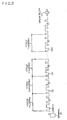
- Figs. 2 and 3 schematically illustrate codes C1 and the like transmitted from GPS satellites 12a and the like.
- the positioning system 10 includes positioning satellites, such as the GPS satellites 12a, 12b, 12c and 12d.
- the GPS 12a and the like transmit radio waves S1, S2, S3 and S4, respectively, on which various codes are putted.
- One of these codes is C/A code.
- the codes C1 through C20 in Fig. 2 are C/A codes.
- the codes C1 through C20 are, for example, the identical code continuously transmitted from the GPS satellite 12a.
- the code C1 is the C/A code transmitted prior to the code C2.
- the codes C1 and the like are an example of positioning standard code.
- the codes C1 and the like are also an example of a PRN (Pseudo Random Noise) code.
- the positioning system 10 includes a terminal 20.
- the terminal 20 includes a GPS apparatus 30, and thus can receive the codes C1 and the like putted on the radio waves S1 and the like from the GPS satellites 12a and the like.
- the terminal 20 then receives C/A codes from three or more of different GPS satellites 12a and the like, allowing positioning of a current position.
- the codes C1 and the like have a cycle of 1 msec (ms), which corresponds to the distance of 300 kilometers (km).
- the codes C1 and the like differ for each of the GPS satellites 12a and the like.
- the terminal 20 identifies which GPS satellite corresponds to the code C1 or the like.
- identification which GPS satellite corresponds to the code C1 or the like is referred to as extraction of the code C1 or the like or the C/A code.
- the distance between each of the GPS satellites 12a and the like and the terminal 20 (hereinafter, referred to as pseudo distance) is calculated using light-speed propagation of the radio wave S1 on which codes are putted based on the difference between the time at which the codes C1 and the like are transmitted from each of the GPS satellites 12a and the like and the time at which the code C1 is received.
- a current position is then positioned based on the position of each of the GPS satellites 12a and the like on the satellite orbit at the current time and the above-mentioned pseudo distance.
- GPS satellites 12a and the like are illustrated in Fig. 1, however, the number of the GPS satellites 12a and the like may be three or five or more.
- the code C1 is configured with 1,023 chips P1 through P1023.
- the chips P1 and the like are a standard unit, which configures the code C1 and indicates a numerical value of 0 or 1.
- the chips P1 and the like are an example of standard unit code.
- each chip P1 or the like is either 0 or 1.
- identification of each chip P1 or the like being either 0 or 1 is referred to as identification of chip P1 and the like.
- the identification of chip P1 and the like is an example of analysis.
- radio waves S1 and the like are subjected to PSK modulation by PN code such as C/A code, spectral width expands. This causes degradation of SNR, making it difficult to identify each chip P1 or the like.
- the GPS receiver receives the C/A code three times from the GPS satellite 12a, and integrates the sampling results of the C/A codes to improve the SNR, for example, as illustrated in Fig. 3 (b), it takes (2+1/1023) msec (ms) to identify the chip P1. This is because the code 1 should be received first, the code 2 should then be received, and the chip P1 section of the code C3 should then be received in order to receive the chip P1 three times. In other words, it takes a certain time determined by a cycle of the C/A code to receive the chip P1.
- the terminal 20 in the embodiment of the invention can identify the chips P1 and the like without restrictions imposed by a certain time determined by the cycle of the C/A code.
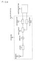
- Fig. 4 schematically illustrates a structure of the GPS apparatus 30.
- the GPS apparatus 30 includes an RF section 32 and a base band section 34.
- the RF section 32 receives C/A codes using an antenna 32a.
- An amplifier LNA32b amplifies the C/A codes.
- a mixer 32c then converts the frequency of the C/A codes.
- a delay circuit 32d including an IQ detector carries out IQ separation of the C/A codes.
- A/D converters 32e1 and 32e2 then converts the C/A codes subjected to IQ separation into digital signals, respectively.
- the base band section 34 receives the C/A codes converted into digital signals from the RF section 32, samples and integrates each chip P1 or the like (see Fig. 3 (a)), and correlates with the C/A codes stored in the base band section 34, thereby identifying the received C/A codes.
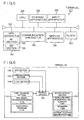
- Fig. 5 schematically illustrates a main hardware structure of the terminal 20.
- the terminal 20 includes a computer, which is equipped with a bus 22.
- a CPU Central Processing Unit
- storage apparatus 26 is connected with the bus 22.
- the storage apparatus may be a RAM (Random Access Memory), a ROM (Read Only Memory), or the like.
- An input apparatus 28, the GPS apparatus 30, a communication apparatus 36, a display apparatus 38, and a clock 40 are also connected with the bus 22.
- Fig. 6 schematically illustrates a main software structure of the terminal 20.
- the terminal 20 includes a control section 100 for controlling each section, a GPS section 102 corresponding to the GPS apparatus 30 in Fig. 5, a communication section 104 corresponding to the communication apparatus 36, a clock section corresponding to the clock 40, and the like.
- the terminal 20 also includes a first storage section 110 for storing each program and a second storage section 150 for storing each pieces of information.
- the terminal 20 stores satellite orbit information 152 in the second storage section 150.
- the satellite orbit information 152 includes almanac 154 and ephemeris 156.
- the almanac 154 is information indicating a rough orbit of all GPS satellites 12a and the like.
- the ephemeris 156 is information indicating an accurate orbit of each of the GPS satellites 12a and the like.
- the terminal 20 uses the almanac 154 and the ephemeris 156 for positioning.
- the terminal 20 stores GPS signal receiving program 112 in the first storage section 110.
- the GPS signal receiving program 112 is a program that the control section 100 receives the C/A codes putted on the radio wave S1 from the GPS satellite 12a or the like using the GPS section 102.
- the GPS apparatus 30 instructed by the control section 100 first receives the C/A codes using the antenna 32a. For example, it is assumed that the code C1 is received from the GPS satellite 12a (see Fig. 3 (c)).
- the code C1 is received by the delay circuit 32d passing through the LNA32b and the mixer 32c.
- the delay circuit 32d generates replica codes C1-1 and C1-2, which are replicas of the code C1, based on the code C1 (see Fig. 3 (c)).
- the replica codes C1-1 and C1-2 are codes for identifying which GPS satellite corresponds to the code C1 by the base band section 34.
- the replica codes C1-1 and C1-2 are an example of analysis assistance codes.
- the delay circuit 32d is an example of analysis assistance code generating means.
- the delay circuit 32d generates the replica code C1-1 having a 1-chip delay with respect to the code C1, and also generates the replica code C1-2 having a 1-chip delay with respect to the replica code C1-1.
- the delay circuit 32d generates the replica codes C1-1 and the like so that the total number of the code C1 and the replica codes C1-1 and the like equals the number required for identifying which GPS satellite corresponds to the code C1 (hereinafter, referred to as the number required for code identification).
- the number required for code identification may be 20, for example, however, it is three herein for simplifying the description
- the number required for code identification is not limited as in this embodiment, but may be changeable for each positioning based on the positioning conditions including receiving intensity of the radio waves S1 and the like, and PDOP (Position Dilution Of Precision) and the like.
- the delay circuit 32d generates the code C1 and the replica codes C1-1 and the like within a range of delay in which the base band section 34 can identify the chip P1 and the like. For example, when the base band section 34 recognizes that the chips P1 and the like having a 1-chip delay, respectively, are, the chips at the identical position in the code C1 and the replica codes C1-1 and the like, the replica codes C1-1 and the like having a 1-chip delay, respectively, with respect to the code C1 are generated as illustrated in Fig. 3 (c).
- the invention is not limited to this embodiment, for example, when the base band section 34 recognizes that the chips P1 and the like having a 2-chip delay, respectively, are the chips at the identical position in the code C1 and the replica codes C1-1 and the like, the replica codes C1-1 and the like having a 2-chip delay, respectively, with respect to the code C1 may be generated.
- the delay circuit 32d also generates the replica codes C1-1 and the like with respect to a part of the code C1. It is not necessary to sample all chips P1 and the like in the code C1 but, for example, only 500 chips when the base band section 34 identifies which GPS satellite corresponds to the code C1. Accordingly, the delay circuit 32d replicates the code C1 in a range required for the base band section 34 to identify which GPS satellite corresponds to the code C1.
- the code C1 and the replica codes C1-1 and the like are subjected to IQ separation by the detector in the delay circuit 32d, and the results are transmitted to the A/D converters 32e1 and 32e2, respectively. As soon as being generated, the code C1 and the replica codes C1-1 and the like converted into digital signals are then transmitted to the base band section 34.
- the code C1 and the replica codes C1-1 and the like are sampled in units of the chip P1 or the like, and the sampling results are integrated.
- the integrated sampling results and the C/A codes stored in the base band section 34 are then correlated, thereby identifying which GPS satellite corresponds to the received code C1.
- the base band section 34 is.an example of the positioning standard code identifying means.
- the replica codes C1-1 and the like are generated so as to have a 1-chip delay with respect to the code C1, respectively. Paying attention to the first chip P1 in the codes C1 and the like, it has a delay of 1/1023 msec (ms), respectively. Accordingly, the base band section 34 takes 3/1023 msec (ms) to receive the replica codes C1-1 and C1-2 after receiving the code C1.
- the base band section 34 takes extremely shorter time, only 3/1023 msec (ms) to receive the replica codes C1-1 and C1-2 after receiving the code C1.
- the base band section 34 identifies which GPS satellite corresponds to the code 1, as well as the phase of the code C1.
- the terminal 20 stores positioning program 114 in the first storage section 110.
- the positioning program 114 is a program that the control section 100 generates current position information 158 indicating a current position based on the identified results by the GPS section 102.
- the positioning program 114 and the control section 100 are an example of the current position information generating means.
- the terminal 20 is configured as described above.
- the terminal 20 can generate the replica codes C1-1 and the like.
- the terminal 20 samples the code C1 and the replica codes C1-1 and the like, and can identify which GPS satellite corresponds to the code C1,
- the terminal 20 when receiving the code C1 once, the terminal 20 can generate the number of replica codes C1-1 and the like required for identifying which GPS satellite corresponds to the code C1 based on the code C1. This means that it is unnecessary for the terminal 20 to receive the number of codes C1 and the like required for identifying which GPS satellite corresponds to the code C1.
- the terminal 20 may integrate the sampling results of the code C1 and the replica codes C1-1 and the like required for extracting the code C1 without restrictions imposed by transmission interval period of the codes C1 and the like.
- the terminal 20 also generates the replica codes C1-1 and the like so that the total number of the code C1 and the replica codes C1-1 and the like equals the number required for identifying which GPS satellite corresponds to the code C1.
- the terminal 20 also generates the replica codes C1-1 and the like within a range of delay in which the base band section 34 can identify the chips P1 and the like which are standard units configuring the code C1.
- the chips P1 and the like allocated at the identical position in the code C1 and the replica codes C1-1 and the like must be integrated with each other.
- the terminal 20 generates the replica codes C1-1 and the like within a range of delay in which the base band section 34 can identify which GPS satellite corresponds to the code C1 or the like. Accordingly, the base band section 34 can identify which GPS satellite corresponds to the code C1 reliably.
- the terminal 20 also generates the replica codes C1-1 and the like with respect to a part of the code C1 or the like.
- the terminal 20 generates the replica codes C1-1 and the like with respect to a part of the code C1 or the like. This allows the terminal 20 to reduce the sampling time and identify which GPS satellite corresponds to the code C1 or the like.
- the structure of the terminal 20 in the embodiment is described above.
- the operation example is hereinafter described mainly using Fig. 7.
- Fig. 7 schematically illustrates a flowchart of an operation example of the terminal 20.
- the terminal 20 receives a C/A code C1 putted on the radio wave S1 from the GPS satellite 12a, for example (step ST1 in Fig. 7).
- step ST2 is an example of the analysis assistance code generating step.
- the terminal 20 integrates the original code C1 and the replica codes C1-1 and the like, and identifies which GPS satellite corresponds to the code C1 (step ST3).
- the step ST3 is an example of the positioning standard code identifying step.
- the terminal 20 then positions a current position, and generates the current position information 158 (see Fig. 6) (step ST4).
- the step ST4 is an example of the current position information generating step.
- the terminal 20 displays the current position information 158 on the display apparatus 38 (see Fig. 5) (step ST5).
- the terminal 20 can integrate the number of times required for extracting the codes C1 and the like without restrictions imposed by transmission interval period of the codes C1 and the like.
- Fig. 8 schematically illustrates a structure of a GPS apparatus 30A in the modified example of the embodiment.
- Fig. 9 schematically illustrates codes C1 and the like.
- the GPS apparatus 30A includes a branch circuit 32f.
- the branch circuit 32f generates replica codes C1-1 and C1-2 without delay with respect to the code C1.
- the base band section 34 can execute sampling for the respective chips P1 in the code C1 and the replica codes C1-1 and C1-2 at once.
- the base band section 34 takes extremely shorter time, only 1/1023 msec (ms) to receive and sample the replica codes C1-1 and C1-2 after receiving the code C1.
- the present invention is not limited to the above-described respective embodiments. Further, the above-described respective embodiments may be combined with each other.
Landscapes
- Engineering & Computer Science (AREA)
- Radar, Positioning & Navigation (AREA)
- Remote Sensing (AREA)
- Physics & Mathematics (AREA)
- General Physics & Mathematics (AREA)
- Computer Networks & Wireless Communication (AREA)
- Theoretical Computer Science (AREA)
- Position Fixing By Use Of Radio Waves (AREA)
Claims (5)
- Eine Positionierungsvorrichtung (30) zum Empfangen eines Positionierungsstandardcodes (C1), der als ein Standard zur Positionierung von einem Positionierungssatelliten (12a) verwendet wird, die Vorrichtung (30) gekennzeichnet zu umfassen:ein Analyseunterstützungscodegenerierungsmittel (32d; 32f) zum Generieren einer Vielzahl von Analyseunterstützungscodes (C1-1, C1-2), die Replika eines empfangenen Positionierungsstandardcodes (C1) umfassen zur Verwendung bei einer Bestimmung, welcher Positionierungssatellit dem empfangenen Positionierungsstandardcode (C1) entspricht;ein Positionierungsstandardcode-Identifikationsmittel (34) zum Analysieren des Positionierungsstandardcodes (C1) und der Analyseunterstützungscodes (C1-1, C1-2), und Identifizieren, welcher Positionierungssatellit dem Positionierungsstandardcode (C1) entspricht, wobei das Positionierungsstandardcode-Identifikationsmittel (34) umfasst:ein Mittel zum Integrieren des empfangenen Positionierungsstandardcodes (C1) und der Vielzahl von generierten Analyseunterstützungscodes (C1-1, C1-2), um ein integriertes Ergebnis zu generieren; undein Mittel zum Korrelieren des integrierten Ergebnisses mit einer Vielzahl von gespeicherten C/A-Codes um zu identifizieren, welcher Positionierungssatellit dem empfangenen Positionierungsstandardcode (C1) entspricht; undein Generierungsmittel aktueller Positionsinformation (100, 114) zum Generieren aktueller Positionsinformation, die eine aktuelle Position anzeigt basierend auf dem identifizierten Ergebnis durch das Positionierungsstandardcode-Identifikationsmittel.
- Die Positionierungsvorrichtung nach Anspruch 1, wobei das Analyseunterstützungscode-Generierungsmittel (32d; 32f) angeordnet ist, die Analyseunterstützungscodes (C1-1, C1-2) zu generieren, sodass die Gesamtzahl des Positionierungsstandardcodes (C1) und der Analyseunterstützungscodes (C1-1, C1-2) gleich der Zahl ist, die zum Identifizieren erforderlich ist, welcher Positionierungssatellit dem Positionierungsstandardcode (C1) entspricht.
- Die Positionierungsvorrichtung nach beliebigen von Ansprüchen 1 und 2, wobei das Analyseunterstützungscode-Generierungsmittel (32d; 32f) angeordnet ist, die Analyseunterstützungscodes (C1-1, C1-2) innerhalb eines Bereiches einer Verzögerung zu generieren, worin das Positionierungsstandardcode-Identifikationsmittel (34) einen Standardeinheitencode identifizieren kann, der eine Standardeinheit ist, die den Positionierungsstandardcode (C1) konfiguriert.
- Die Positionierungsvorrichtung nach beliebigen von Ansprüchen 1 bis 3, wobei das Analyseunterstützungscode-Generierungsmittel (32d; 32f) angeordnet ist, die Analyseunterstützungscodes (C1-1, C1-2) mit Bezug auf einen Teil des Positionierungsstandardcodes (C1) zu generieren.
- Ein Positionierungsverfahren zum Empfangen eines Positionierungsstandardcodes (C1), der als ein Standard verwendet wird zum Positionieren von einem Positionierungssatelliten (12a), das Verfahren gekennzeichnet zu umfassen:einen Analyseunterstützungscode-Generierungsschritt (ST2), in dem eine Positionierungsvorrichtung (30) eine Vielzahl von Analyseunterstützungscodes (C1-1, C1-2) generiert, umfassend Replika eines empfangenen Positionierungsstandardcodes (C1) zur Verwendung bei einer Bestimmung, welcher Positionierungssatellit dem empfangenen Positionierungsstandardcode (C1) entspricht;einen Positionierungsstandardcode-Identifikationsschritt (ST3), in dem die Positionierungsvorrichtung (30) den Positionierungsstandardcode (C1) und die Analyseunterstützungscodes (C1-1, C1-2) analysiert, und identifiziert, welcher Positionierungssatellit dem Positionierungsstandardcode (C1) entspricht, wobei der Positionierungsstandardcode-Identifikationsschritt umfasst:Integrieren des empfangenen Positionierungsstandardcodes (C1) und der Vielzahl von generierten Analyseunterstützungscodes (C1-1, C1-2), um ein integriertes Ergebnis zu generieren; undKorrelieren des integrierten Ergebnisses mit einer Vielzahl von gespeicherten C/A-Codes um zu identifizieren, welcher Positionierungssatellit dem empfangenen Positionierungsstandardcode (C1) entspricht; undeinen Generierungsschritt aktueller Positionsinformation (ST4), in dem die Positionierungsvorrichtung (30) aktuelle Positionsinformation generiert, die eine aktuelle Position anzeigt basierend auf dem identifizierten Ergebnis durch den Positionierungsstandardcode-Identifikationsschritt.
Applications Claiming Priority (1)
| Application Number | Priority Date | Filing Date | Title |
|---|---|---|---|
| JP2005138093A JP4193811B2 (ja) | 2005-05-11 | 2005-05-11 | 測位装置、測位方法 |
Publications (2)
| Publication Number | Publication Date |
|---|---|
| EP1724601A1 EP1724601A1 (de) | 2006-11-22 |
| EP1724601B1 true EP1724601B1 (de) | 2008-01-30 |
Family
ID=36506273
Family Applications (1)
| Application Number | Title | Priority Date | Filing Date |
|---|---|---|---|
| EP06008665A Ceased EP1724601B1 (de) | 2005-05-11 | 2006-04-26 | Positionierungsvorrichtung und Positionierungsverfahren |
Country Status (6)
| Country | Link |
|---|---|
| US (1) | US20070075897A1 (de) |
| EP (1) | EP1724601B1 (de) |
| JP (1) | JP4193811B2 (de) |
| KR (1) | KR100768987B1 (de) |
| CN (1) | CN1862287A (de) |
| DE (1) | DE602006000498T2 (de) |
Family Cites Families (10)
| Publication number | Priority date | Publication date | Assignee | Title |
|---|---|---|---|---|
| US6633255B2 (en) * | 1995-10-09 | 2003-10-14 | Qualcomm Inc. | Method for open loop tracking GPS signals |
| US5610984A (en) * | 1995-11-22 | 1997-03-11 | Trimble Navigation Limited | Optimal L2 tracking in a SPS receiver under encryption without knowledge of encryption timing characteristics |
| JPH10339772A (ja) | 1997-04-11 | 1998-12-22 | Iwaki Electron Corp Ltd | Gps用rfモジュール |
| US6407699B1 (en) * | 2000-04-14 | 2002-06-18 | Chun Yang | Method and device for rapidly extracting time and frequency parameters from high dynamic direct sequence spread spectrum radio signals under interference |
| US6292748B1 (en) * | 2000-07-14 | 2001-09-18 | General Electric Company | Reduction of time error in GPS localization without a highly accurate clock |
| US6990140B2 (en) * | 2001-05-17 | 2006-01-24 | Trimble Navigation Limited | Signal receiver using coherent integration in interleaved time periods for signal acquisition at low signal strength |
| US7190712B2 (en) * | 2001-05-18 | 2007-03-13 | Global Locate, Inc | Method and apparatus for performing signal correlation |
| US6856282B2 (en) * | 2002-02-08 | 2005-02-15 | Qualcomm Incorporated | Directly acquiring precision code GPS signals |
| US6788663B2 (en) * | 2002-05-03 | 2004-09-07 | Qualcomm Inc | System, method, and apparatus for generating a timing signal |
| US7292186B2 (en) * | 2003-04-23 | 2007-11-06 | Csi Wireless Inc. | Method and system for synchronizing multiple tracking devices for a geo-location system |
-
2005
- 2005-05-11 JP JP2005138093A patent/JP4193811B2/ja not_active Expired - Fee Related
-
2006
- 2006-04-17 CN CNA2006100725001A patent/CN1862287A/zh active Pending
- 2006-04-26 DE DE602006000498T patent/DE602006000498T2/de not_active Expired - Lifetime
- 2006-04-26 EP EP06008665A patent/EP1724601B1/de not_active Ceased
- 2006-04-28 KR KR1020060038691A patent/KR100768987B1/ko not_active Expired - Fee Related
- 2006-05-10 US US11/431,105 patent/US20070075897A1/en not_active Abandoned
Also Published As
| Publication number | Publication date |
|---|---|
| CN1862287A (zh) | 2006-11-15 |
| KR20060116697A (ko) | 2006-11-15 |
| DE602006000498D1 (de) | 2008-03-20 |
| KR100768987B1 (ko) | 2007-10-22 |
| EP1724601A1 (de) | 2006-11-22 |
| JP2006317211A (ja) | 2006-11-24 |
| DE602006000498T2 (de) | 2009-02-12 |
| US20070075897A1 (en) | 2007-04-05 |
| JP4193811B2 (ja) | 2008-12-10 |
Similar Documents
| Publication | Publication Date | Title |
|---|---|---|
| US7283091B1 (en) | Radio positioning system for providing position and time for assisting GPS signal acquisition in mobile unit | |
| US7965230B2 (en) | Satellite time determination for SPS receiver | |
| US6922546B1 (en) | GPS signal acquisition based on frequency-domain and time-domain processing | |
| FI112893B (fi) | Menetelmä vastaanottimessa ja vastaanotin | |
| US20040176102A1 (en) | Multiple antenna multi-frequency measurement system | |
| JP3785210B2 (ja) | 広域測位システム用並列相関器 | |
| WO2005109028A1 (en) | Method and apparatus for processing satellite positioning system signals | |
| AU2003279161A1 (en) | Satellite-based positioning system improvement | |
| US7295156B2 (en) | Cellphone GPS positioning system | |
| EP2354802A1 (de) | Verfahren zur Selbstkalibrierung von Frequenzversätzen | |
| EP1829232A1 (de) | Bestimmung einer kodephase | |
| US6154173A (en) | Method and apparatus for processing multipath reflection effects in timing systems | |
| US8284818B2 (en) | Spread spectrum transmission systems | |
| US6009335A (en) | Method of calibrating and testing spatial nulling antenna | |
| US8184505B1 (en) | High sensitivity GPS-assisted time source | |
| US7876738B2 (en) | Preventing an incorrect synchronization between a received code-modulated signal and a replica code | |
| EP1724601B1 (de) | Positionierungsvorrichtung und Positionierungsverfahren | |
| US20050232380A1 (en) | Support of the determination of a correlation | |
| US7057554B2 (en) | Bootstrapping tandem GPS navigation receivers | |
| KR101860328B1 (ko) | 장치 및 방법 | |
| HK1099080A (en) | Positioning apparatus and positioning method | |
| US20030086483A1 (en) | Method and apparatus for spread spectrum signal acquisition | |
| Qaisar et al. | Loud and Clear: Receiving the new GPS L2C and Galileo signals | |
| HK1232605A1 (en) | Gnss receiver calculating a non-ambiguous discriminator to resolve subcarrier tracking ambiguities | |
| HK1232605A (en) | Gnss receiver calculating a non-ambiguous discriminator to resolve subcarrier tracking ambiguities |
Legal Events
| Date | Code | Title | Description |
|---|---|---|---|
| PUAI | Public reference made under article 153(3) epc to a published international application that has entered the european phase |
Free format text: ORIGINAL CODE: 0009012 |
|
| AK | Designated contracting states |
Kind code of ref document: A1 Designated state(s): AT BE BG CH CY CZ DE DK EE ES FI FR GB GR HU IE IS IT LI LT LU LV MC NL PL PT RO SE SI SK TR |
|
| AX | Request for extension of the european patent |
Extension state: AL BA HR MK YU |
|
| 17P | Request for examination filed |
Effective date: 20070503 |
|
| 17Q | First examination report despatched |
Effective date: 20070601 |
|
| GRAP | Despatch of communication of intention to grant a patent |
Free format text: ORIGINAL CODE: EPIDOSNIGR1 |
|
| AKX | Designation fees paid |
Designated state(s): DE FR GB |
|
| REG | Reference to a national code |
Ref country code: HK Ref legal event code: DE Ref document number: 1099080 Country of ref document: HK |
|
| GRAC | Information related to communication of intention to grant a patent modified |
Free format text: ORIGINAL CODE: EPIDOSCIGR1 |
|
| GRAS | Grant fee paid |
Free format text: ORIGINAL CODE: EPIDOSNIGR3 |
|
| GRAA | (expected) grant |
Free format text: ORIGINAL CODE: 0009210 |
|
| AK | Designated contracting states |
Kind code of ref document: B1 Designated state(s): DE FR GB |
|
| REG | Reference to a national code |
Ref country code: GB Ref legal event code: FG4D |
|
| REF | Corresponds to: |
Ref document number: 602006000498 Country of ref document: DE Date of ref document: 20080320 Kind code of ref document: P |
|
| EN | Fr: translation not filed | ||
| PLBE | No opposition filed within time limit |
Free format text: ORIGINAL CODE: 0009261 |
|
| STAA | Information on the status of an ep patent application or granted ep patent |
Free format text: STATUS: NO OPPOSITION FILED WITHIN TIME LIMIT |
|
| 26N | No opposition filed |
Effective date: 20081031 |
|
| PG25 | Lapsed in a contracting state [announced via postgrant information from national office to epo] |
Ref country code: FR Free format text: LAPSE BECAUSE OF FAILURE TO SUBMIT A TRANSLATION OF THE DESCRIPTION OR TO PAY THE FEE WITHIN THE PRESCRIBED TIME-LIMIT Effective date: 20081121 |
|
| GBPC | Gb: european patent ceased through non-payment of renewal fee |
Effective date: 20100426 |
|
| PG25 | Lapsed in a contracting state [announced via postgrant information from national office to epo] |
Ref country code: GB Free format text: LAPSE BECAUSE OF NON-PAYMENT OF DUE FEES Effective date: 20100426 |
|
| REG | Reference to a national code |
Ref country code: HK Ref legal event code: WD Ref document number: 1099080 Country of ref document: HK |
|
| PGFP | Annual fee paid to national office [announced via postgrant information from national office to epo] |
Ref country code: DE Payment date: 20140430 Year of fee payment: 9 |
|
| REG | Reference to a national code |
Ref country code: DE Ref legal event code: R119 Ref document number: 602006000498 Country of ref document: DE |
|
| PG25 | Lapsed in a contracting state [announced via postgrant information from national office to epo] |
Ref country code: DE Free format text: LAPSE BECAUSE OF NON-PAYMENT OF DUE FEES Effective date: 20151103 |