EP1724174A2 - Adaptive cruise control - Google Patents
Adaptive cruise control Download PDFInfo
- Publication number
- EP1724174A2 EP1724174A2 EP06252630A EP06252630A EP1724174A2 EP 1724174 A2 EP1724174 A2 EP 1724174A2 EP 06252630 A EP06252630 A EP 06252630A EP 06252630 A EP06252630 A EP 06252630A EP 1724174 A2 EP1724174 A2 EP 1724174A2
- Authority
- EP
- European Patent Office
- Prior art keywords
- vehicle
- control
- state
- following
- speed
- Prior art date
- Legal status (The legal status is an assumption and is not a legal conclusion. Google has not performed a legal analysis and makes no representation as to the accuracy of the status listed.)
- Granted
Links
Images




Classifications
-
- B—PERFORMING OPERATIONS; TRANSPORTING
- B60—VEHICLES IN GENERAL
- B60W—CONJOINT CONTROL OF VEHICLE SUB-UNITS OF DIFFERENT TYPE OR DIFFERENT FUNCTION; CONTROL SYSTEMS SPECIALLY ADAPTED FOR HYBRID VEHICLES; ROAD VEHICLE DRIVE CONTROL SYSTEMS FOR PURPOSES NOT RELATED TO THE CONTROL OF A PARTICULAR SUB-UNIT
- B60W30/00—Purposes of road vehicle drive control systems not related to the control of a particular sub-unit, e.g. of systems using conjoint control of vehicle sub-units
- B60W30/14—Adaptive cruise control
- B60W30/16—Control of distance between vehicles, e.g. keeping a distance to preceding vehicle
- B60W30/17—Control of distance between vehicles, e.g. keeping a distance to preceding vehicle with provision for special action when the preceding vehicle comes to a halt, e.g. stop and go
Definitions
- the present invention relates to vehicle control and particularly, but not exclusively, to an apparatus and method for a vehicle for controlling the vehicle whilst following a preceding vehicle.
- Emobdiments of the invention relate to an apparatus, a device, a system, a vehicle and a method.
- a controller for following a preceding vehicle and for automatic following of the preceding vehicle is known from, for example, Japanese Kokai Patent Application No.1999-354552 .
- the control for following the preceding vehicle is released, and only control of the brake force is continued.
- the brake force control is released. Consequently, when the preceding vehicle stops and then moves forward again, it is necessary to brake to keep the automobile stopped, to perform an acceleration operation to move the automobile forward and to perform a switch operation to restart the control for following the preceding vehicle.
- an apparatus for controlling a vehicle to follow a preceding vehicle wherein a stop-holding device is arranged to maintain a stopped state automatically when the vehicle is stopped and the stop-holding device is in an enabled state or a disabled state and wherein a control state for following the preceding vehicle is changed, at least in part, according to a set state of the stop-holding device.
- an apparatus for a vehicle for following a preceding vehicle comprising an inter-vehicle distance sensor that detects an inter-vehicle distance between the vehicle and the preceding vehicle, a brake device that decelerates the vehicle, a stop-holding device that maintains a stopped state automatically when the vehicle is stopped, an operation member for setting the stop-holding device in one of an enabled state and a disabled state and a controller operable to perform control for following the preceding vehicle using the brake device based on a signal from the inter-vehicle distance sensor and operable to use the operation member to change a control state for following the preceding vehicle according to a set state of the stop-holding device.
- the apparatus may comprise a vehicle speed sensor arranged to detect a vehicle speed.
- the controller may be operable to perform a first following control operation that releases the control for following the preceding vehicle when the vehicle speed is lower than a first prescribed vehicle speed when the stop-holding device is in the disabled state.
- the controller is operable to perform a second following control while following the preceding vehicle until the vehicle is stopped when the stop-holding device is in the enabled state.
- the controller is operable to stop the vehicle while control for following the preceding vehicle is released when the preceding vehicle is lost from view by the inter-vehicle distance sensor and when the vehicle speed falls below a second prescribed vehicle speed in the second following control.
- the controller is operable to release the control for following the preceding vehicle when the stop-holding device is changed from the enabled state to the disabled state when the vehicle speed falls below the first prescribed vehicle speed during the second following control.
- the controller is operable to switch from the second following control to the first following control when the stop-holding device is changed from the enabled state to the disabled state when the vehicle speed rises above the first prescribed vehicle speed during the second following control.
- the controller is operable to set a target inter-vehicle distance in the first following control that is longer than a preset value when the stop-holding device changes from the enabled state to the disabled state due to generation of an abnormality in the stop-holding device.
- the apparatus may comprise a notifying device that generates a notification chime at a prescribed running scenario during the control for following the preceding vehicle, the notifying device operable to generate different chimes in the first following control and the second following control.
- the controller is further operable to make a stop-holding mode of the stop-holding device a priority without advancing the vehicle even if the preceding vehicle is advancing if the stop-holding mode is performed with the stop-holding device during the second following control.
- the inter-vehicle distance sensor is operable to increase a range of the sensor when the vehicle advances subsequent to a state of remaining stopped by the stop-holding device in the second following control.
- the apparatus may comprise a display device that displays at least one of the enabled state of the stop-holding device, the disabled state of the stop-holding device, a status of the first following control and a status of the second following control.
- the controller is operable to execute a high-speed following control when the vehicle is at a speed in a high-speed range and a low-speed following control when the vehicle is at a speed in a low-speed range.
- the controller via the operation member, may be operable to change a control state of the low-speed following control corresponding to the set state of the stop-holding device.
- an apparatus for a vehicle for following a preceding vehicle comprising an inter-vehicle distance sensor that detects an inter-vehicle distance between the vehicle and the preceding vehicle, a brake device that decelerates the vehicle, a stop-holding device that maintains a stopped state automatically when the vehicle is stopped, an operation member for setting the stop-holding device in one of an enabled state and a disabled state and a controller operable to perform control for following the preceding vehicle using the brake device based on a signal from the inter-vehicle distance sensor and operable to perform a following control while following the preceding vehicle until the vehicle is stopped when the stop-holding device is in the enabled state.
- a control system for a vehicle for following a preceding vehicle that performs control for following the preceding vehicle based on an inter-vehicle distance from the preceding vehicle, the control system comprising a judgment device that determines whether a stop-holding device operable to automatically maintain a stopped state is in one of an enabled state and a disabled state once the vehicle is stopped and a control state switching device operable to maintain the control for following the preceding vehicle until the vehicle is stopped if the judgment device indicates that the stop-holding device is in the enabled state and to release the control for following the preceding vehicle once a vehicle speed falls below a prescribed vehicle speed if the judgment device indicates that the stop-holding device is in the disabled state.
- a method for control of a vehicle for following a preceding vehicle comprising setting a stop-holding device that can automatically maintain a stopped state in one of an enabled state and a disabled state once the vehicle is stopped, determining whether the stop-holding device is in the enabled state or the disabled state; and changing a control state of the control for following the preceding vehicle in response to whether the stop-holding device is in the enabled state or the disabled state.
- the method may comprise executing a high-speed following control when the vehicle is at a speed in a high-speed range and executing a low-speed following control when the vehicle is at a speed in a low-speed range; and wherein changing the control state further includes changing a control state of the low-speed following control corresponding to a state of the stop-holding device.
- the method may comprise detecting a vehicle speed of the vehicle and performing a first following control operation that releases the control for following the preceding vehicle when the vehicle speed is lower than a first prescribed vehicle speed when the stop-holding device is in the disabled state.
- the method may comprise performing a second following control while following the preceding vehicle until the vehicle is stopped when the stop-holding device is in the enabled state.
- the method comprises stopping the vehicle while control for following the preceding vehicle is released when the preceding vehicle is lost from view and when the vehicle speed falls below a second prescribed vehicle speed in the second following control.
- the method may comprise releasing the control for following the preceding vehicle when the stop-holding device is changed from the enabled state to the disabled state when the vehicle speed falls below the first prescribed vehicle speed during the second following control.
- Embodiments of the invention provide an apparatus for a vehicle for following a preceding vehicle.
- the apparatus may comprise, for example, an inter vehicle distance sensor that detects the inter vehicle distance between the vehicle and the preceding vehicle, a brake device that decelerates the vehicle, a stop-holding device that maintains a stopped state automatically when the vehicle is stopped, an operation member for setting the stop-holding device in one of an enabled state and a disabled state, and a controller.
- the controller may be operable to perform control for following the preceding vehicle using the brake device based on a signal from the inter vehicle distance sensor and operable to use the operation member to change a control state for following the preceding vehicle according to a set state of the stop-holding device.
- Embodiments of the invention also provide a control system for a vehicle for following a preceding vehicle that performs control for following the preceding vehicle based on the inter vehicle distance from the preceding vehicle.
- the control system can comprise a judgment device that determines whether a stop-holding device operable to automatically maintain a stopped state is in one of an enabled state and a disabled state once the vehicle is stopped and a control state switching device operable to maintain the control for following the preceding vehicle until the vehicle is stopped if the judgment device indicates that the stop-holding device is in the enabled state and to release the control for following the preceding vehicle once a vehicle speed falls below a prescribed vehicle speed if the judgment device indicates that the stop-holding device is in the disabled state.
- a method for control of a vehicle for following a preceding vehicle may comprise setting a stop-holding device that can automatically maintain a stopped state in one of an enabled state and a disabled state once the vehicle is stopped, determining whether the stop-holding device is in the enabled state or the disabled state and changing a control state of the control for following the preceding vehicle in response to whether the stop-holding device is in the enabled state or the disabled state.
- the invention may permit control of the vehicle for following the preceding vehicle appropriately corresponding to the state of the stop-holding device.
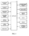
- Figure 1 is a diagram illustrating one example of an apparatus for following a preceding vehicle.
- the apparatus has a number of parts, including shift position sensor 1, acceleration sensor 2, vehicle speed sensor 3, inter-vehicle distance sensor 4, throttle actuator 5, brake actuator 6, brake switch 7, electric-powered parking brake switch 8 (hereinafter to be referred to as EPKB switch 8), electric-powered brake 9 (hereinafter to be referred to as EPKB 9), operation switch 10, display 11, speaker 12, automatic stop-holding switch 13 and controller 20.
- EPKB 9 performs stop-holding functions
- EPKB switch 8 performs operation functions.
- Vehicle speed sensor 3 performs the function of vehicle speed detecting.
- Either display 11 or speaker 12 or both perform notification functions, while display 11 additionally performs display functions. Each of these elements is discussed in more detail hereinafter.
- Shift position sensor 1 detects the current shift position.
- Acceleration sensor 2 detects the fact of stepping on the acceleration pedal.
- Vehicle speed sensor 3 detects the vehicle speed.
- Inter-vehicle distance sensor 4 has a radar device. By sending a laser beam ahead of the vehicle, the preceding vehicle is detected, and, at the same time, the inter-vehicle distance to the preceding vehicle is detected.
- Controller 20 performs control functions as discussed in more detail herein. Based on the instruction from controller 20, throttle actuator 5 controls opening of a throttle valve (not shown) to control acceleration/deceleration of vehicle. Based on the instruction from controller 20, brake actuator 6 controls the brake force of the hydraulic brake (not shown) set in each vehicle.
- controller 20 Based on the inter-vehicle distance detected by inter-vehicle distance sensor 4 and the speed of the automobile detected by vehicle speed sensor 3, controller 20 performs control for following the preceding vehicle so that the automobile follows the preceding vehicle automatically. That is, when the preceding vehicle is detected, throttle actuator 5 and brake actuator 6 are controlled so that the inter-vehicle distance is kept constant between the automobile and the preceding vehicle.
- Brake switch 7 detects that the brake pedal (not shown) is stepped on.
- EPKB switch 8 is a switch for working/release of EPKB 9 to be explained later.
- EPKB 9 set on the left/right rear wheels is turned ON.
- a brake wire is wound up by a motor (not shown) so that a frictional member is pressed on the brake disk (not shown) to lock the wheels.
- the vehicle can still maintain the stopped state.
- Automatic stop-holding switch 13 is a switch for turning ON/OFF the automatic stop-holding system. Next, the automatic stop-holding system is explained. When the automatic stop-holding system is ON, and the driver steps on the brake pedal to stop the vehicle, controller 20 turns ON EPKB 9. EPKB 9 operates independently of turning ON of EPKB switch 8 by the driver. As a result, even if the driver does not step on the brake pedal, the stopped state of the vehicle still can be maintained.
- an automatic stop-holding system a system that performs stop-holding control with EPKB 9 when the vehicle stops.
- a change of the automatic stop-holding system from the ON to the OFF state is not limited to the case when automatic stop-holding switch 13 is turned ON.
- a change from ON to OFF also takes place if an abnormality occurs in the automatic stop-holding system.
- the state of control for following the preceding vehicle is changed corresponding to the ON/OFF state of automatic stop-holding switch 13.
- Operation switch 10 is a switch for performing various control operations for following the preceding vehicle.
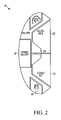
- Figure 2 is a diagram illustrating in detail an example of an operation switch 10. Operation switch 10 is set at a position on the steering wheel that allows easy operation.
- Main switch 21 is a switch for turning ON/OFF the control system for following the preceding vehicle.
- Resume/acceleration switch 22 is a switch for increasing the speed when control for following the preceding vehicle is performed.
- Set/coast switch 23 is a switch for lowering the speed when control for following the preceding vehicle is performed. When set/coast switch 23 or main switch 21 is pressed, and the control system for following the preceding vehicle is ON, the control for following the preceding vehicle is actually started with the switch.
- Cancel switch 24 is a switch for releasing the control for following the preceding vehicle when control for following the preceding vehicle is carried out.
- Inter-vehicle setting switch 25 is a switch for changing the inter-vehicle distance (the target inter-vehicle distance) to the preceding vehicle.
- Display 11 is set at a position that can be easily viewed by the driver, and it displays the control state and the operating state of EPKB 9 (i.e., whether or not it is in an enabled state).
- speaker 12 chimes to indicate a change in the control state.
- Figure 3 is a diagram illustrating transition of the various control states of the stop-holding control in the automatic stop-holding system.
- States 31 and 32 are the OFF state of the automatic stop-holding system. Of them, state 31 refers to the state in which EPKB 9 is turned ON by means of ON of EPKB switch 8, and state 32 is the state in which EPKB 9 does not operate.
- state 31 or state 32 when the automatic stop-holding system is OFF, and automatic stop-holding switch 13 is turned ON the automatic stop-holding system comes ON. In this case, if the vehicle speed is higher than 0 km/h, state 33 is entered.
- State 33 is a state in which the automatic stop-holding system is ON, and system start control of the vehicle is performed, that is, the standby operational state of the automatic stop-holding system.
- state 34 stop-holding control of the vehicle is performed by EPKB 9 (ON state of the stop-holding control). Also, in state 33 when the vehicle speed is 0 km/h, that is, the vehicle is stopped, state 34 is entered.
- state 34 when stop-holding control is performed, and the driver steps on the acceleration pedal, ON of EPKB 9 is released.
- State 33 is entered, that is, the standby state of the stop-holding control.
- state 31 is entered. That is, in the state when vehicle stop-holding control is performed with EPKB 9, and the automatic stop-holding system is released while stop-holding control is continued with EPKB 9, the automatic stop-holding system is turned OFF.
- Figure 4 is a diagram illustrating transition of the various control states for following the preceding vehicle.
- state 41 the control system for following the preceding vehicle is turned OFF.
- state 42 the control system for following the preceding vehicle is turned ON, and the system is in the standby state without start of the control for following the preceding vehicle.
- standby state 42 when main switch 21 is pressed the control system for following the preceding vehicle is turned OFF.
- State 41 is entered.
- states performing control for following the preceding vehicle are states 43-45.
- control for following the preceding vehicle is performed for vehicle speeds in the range of 40-100 km/h.
- states 44 and 45 the vehicle speed is lower than 40 km/h, and control for following the preceding vehicle is performed.
- state 43 is called the high-speed region operating state, or the high-speed running state.
- state 44 the automatic stop-holding system is OFF, and control for following the preceding vehicle is performed when the vehicle speed is in the range of 5-40 km/h.
- state 44 is called the first low-speed following state.
- state 45 the automatic stop-holding system is ON, and control for following the preceding vehicle is performed when the vehicle speed is in the range of 0-40 km/h.
- state 45 is called the second low-speed following state. That is, in one embodiment by means of ON/OFF of the automatic stop-holding system, the control content of the control for following the preceding vehicle is changed.
- the vehicle speed is in the range of 40-100 km/h, and the driver does not step on the brake pedal. Also, when the driver presses set/coast switch 23, high-speed running state 43 is entered. In high-speed running state 43, when a preceding vehicle is detected ahead of the automobile, the vehicle speed preset by the driver is taken as an upper limit, and at the preset inter-vehicle distance control for following is performed. When no preceding vehicle is detected, control is performed so that the driver has the vehicle run at the preset vehicle speed (the set vehicle speed).
- first low-speed following state 44 when the vehicle speed rises above 40 km/h, and the set vehicle speed for constant-speed running in high-speed running state 43 is set by the driver, high-speed running state 43 is entered. However, in high-speed running state 43, when the vehicle speed falls below 40 km/h while a preceding vehicle is detected, and the automatic stop-holding system goes OFF. First low-speed following state 44 is entered.
- second low-speed following state 45 if the vehicle speed is 5 km/h or higher the automatic stop-holding system goes OFF at the time first low-speed following state 44 is entered. However, in first low-speed following state 44, when the automatic stop-holding system enters the automatic standby state second low-speed following state 45 is entered.
- second low-speed following state 45 if the vehicle speed reaches 40 km/h or higher, and a set vehicle speed for constant speed running in high-speed running state 43 is set by the driver, high-speed running state 43 is entered. However, in high-speed running state 43 if the vehicle speed falls below 40 km/h, and the automatic stop-holding system enters the standby state while a preceding vehicle is detected, second low-speed following state 45 is entered.
- FIG. 5A shows the display state of display 11 in first low-speed following state 44.
- Figure 5B shows the display state of display 11 in second low-speed following state 45.
- display 11 together with the vehicle speedometer, the vehicle speed range where control for following the preceding vehicle is performed as well as the ON/OFF state of the automatic stop-holding system are displayed.
- first low-speed following state 44 the fact that the vehicle speed range where control for following the preceding vehicle is performed is 5 km/h or higher is displayed on display 11. At the same time, the automatic stop-holding system is OFF. In first low-speed following state 44, the vehicle speed range where control for following the preceding vehicle is performed is in the range of 5-40 km/h. If the vehicle speed is over 40 km/h high-speed running state 43 is entered, and control for following the preceding vehicle is continued. Consequently, as shown in Figure 5A the vehicle speed range where control for following the preceding vehicle is performed is displayed as a range of 5-100 km/h.
- second low-speed following state 45 the fact that the vehicle speed range where control for following the preceding vehicle is performed is over 0 km/h is displayed on display 11.
- the automatic stop-holding system is shown to be ON.
- the fact that the automatic stop-holding system is ON is displayed by the text "Auto Parking.”
- the upper limit of the vehicle speed range where control for following the preceding vehicle is performed is displayed as 100 km/h instead of 40 km/h (see Figure 5B).
- FIG. 6 is a flow chart illustrating the content of processing performed by controller 20 when the vehicle is in first low-speed following state 44.
- controller 20 starts the processing at step S10.
- step S 10 a judgment is made as to whether the vehicle speed detected by vehicle speed sensor 3 is 40 km/h or higher. If the vehicle speed is over 40 km/h, the process goes to step S20, and control for following the preceding vehicle is performed in high-speed running state 43.
- step S10 if the vehicle speed is below 40 km/h the process goes to step S30.
- step S30 judgment is made as to whether main switch 21 is pressed. If main switch 21 is pressed, the process goes to step S40.
- step S40 the control system for following the preceding vehicle is turned OFF. As a result, the control for following the preceding vehicle goes from first low-speed following state 44 to state 41.
- step S30 if it is judged that main switch 21 is not pressed, the process goes to step S50.
- step S50 judgment is made as to whether any one condition among conditions (b)-(d) is met, that is, whether the driver is executing any one of brake operation, operation of cancel switch 24 or shifting of the gear to a position other than drive (D).
- brake switch 7, operation switch 10 and shift position sensor 1 Based on signals input from brake switch 7, operation switch 10 and shift position sensor 1, it is judged that one of the operations is performed by the driver, that is, brake operation, pressing of cancel switch 24 or shifting the gear to a position other than drive (D).
- step S60 if the judgment result is that none of these operations is being performed, the process goes to step S70.
- step S70 judgment is made as to whether the preceding vehicle is lost from view based on the signal input from inter-vehicle distance sensor 4. If the preceding vehicle has been lost from view, the process goes to step S60. If not, the process goes to step S80. In step S80 judgment is made as to whether the vehicle speed detected by vehicle speed sensor 3 is lower than 5 km/h. If the vehicle speed is lower than 5 km/h, the process goes to step S60. If the vehicle speed is not lower than 5 km/h at step S80, the process goes to step S90.
- step S60 the control for following the preceding vehicle is released. As a result, the control for following the preceding vehicle changes from first low-speed following state 44 to standby state 42.
- step S90 judgment is made as to whether the automatic stop-holding system is in the standby state.
- first low-speed following state 44 the automatic stop-holding system is OFF. If the driver presses automatic stop-holding switch 13, and the automatic stop-holding system is in the standby state, the process goes to step S100.
- step S 100 control for following the preceding vehicle is performed in second low-speed following state 45. That is, the control for following the preceding vehicle changes from first low-speed following state 44 to second low-speed following state 45.
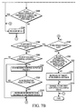
- Figures 7A and 7B include a flow chart illustrating the content of processing by means of controller 20 when the control for following the preceding vehicle is in second low-speed following state 45.
- controller 20 starts the proceeds from step S200.
- step S200 judgment is made as to whether the vehicle speed detected by vehicle speed sensor 3 is over 40 km/h. If the vehicle speed is over 40 km/h, the process goes to step S210, and control for following the preceding vehicle is performed in high-speed running state 43.
- step S200 if the vehicle speed is lower than 40 km/h, the process goes to step S220.
- step S220 judgment is made as to whether main switch 21 is pressed. If main switch 21 is pressed, the process goes to step S230.
- step S230 the control system for following the preceding vehicle is turned OFF. As a result, the control for following the preceding vehicle changes from second low-speed following state 45 to state 41.
- step S220 when main switch 21 is not pressed the process goes to step S240.
- step S240 based on the signal input from inter-vehicle distance sensor 4, judgment is made as to whether the preceding vehicle is lost from view. If the preceding vehicle is lost from view, the process goes to step S250.
- step S250 judgment is made as to whether the vehicle speed detected by vehicle speed sensor 3 is over a prescribed vehicle speed. Here, assume that the prescribed vehicle speed is 3 km/h. Then, in step S250, if the vehicle speed is over 3 km/h, the process goes to step S380. However, if the vehicle speed is lower than 3 km/h, the process goes to step S260.
- step S260 an operation instruction is sent to a hydraulic brake with respect to brake actuator 6 to change the vehicle speed to 0 km/h.
- the control for following the preceding vehicle is released, and the standby state is entered.
- the hydraulic brake is turned ON (when the hydraulic brake is turned ON, working of the hydraulic brake continues).
- an instruction to release the hydraulic brake is output to brake actuator 6.
- EPKB 9 is turned ON.
- step S270 judgment is made as to whether the automatic stop-holding control is turned ON, that is, whether the stop-holding control of the vehicle with EPKB 9 is ON. If EPKB 9 performs stop-holding control of the vehicle, the process goes to step 5380. If EPKB 9 is not working, the process returns to step S260. The hydraulic brake continues to work.
- second low-speed following state 45 when the automobile follows the preceding vehicle and decelerates, a change occurs from the hydraulic brake used for deceleration of the vehicle to EPKB 9, and the vehicle is maintained in a stopped state. Even after stopping the vehicle, to keep the hydraulic brake working it is necessary to keep current flowing in brake actuator 6. When the vehicle stops, and a change is made to EPKB 9, it is possible to prevent the continuation of current flow in brake actuator 6.
- step S240 if the preceding vehicle is not lost from view, the process goes to step S280.
- step S280 judgment is made as to whether any one of conditions (b)-(d) is met, that is, whether any one of these operations are performed by the driver: brake operation, pressing of cancel switch 24 or shifting the gear to a position other than drive (D). If the operation is one of the operations performed by the driver, that is, brake operation, pressing of cancel switch 24 or shifting the gear to a position other than drive (D), based on the signals input from brake switch 7, operation switch 10 and shift position sensor 1, the process goes to step S380. On the other hand, if none of these operations is performed, the process goes to step S290.
- step S290 it is judged whether the automatic stop-holding system is OFF. As explained above, when the automatic stop-holding system is ON, if the driver presses automatic stop-holding switch 13 or if any abnormality occurs in the automatic stop-holding system, the automatic stop-holding system is turned OFF. If the automatic stop-holding system is turned OFF the process goes to step S340. On the other hand, if the system is kept ON the process goes to step S300.
- step S300 judgment is made as to whether the stop-holding control of the vehicle is performed with EPKB 9. As explained above, when the vehicle following the preceding vehicle decelerates and stops, switching is made from the hydraulic brake to EPKB 9, and the vehicle is maintained in a stopped state. If the stop-holding control is performed with EPKB 9, the process goes to step S310. Stop-holding control is not performed. On the other hand, if the vehicle is running the process returns to step S200.
- step S310 the stopped state of the vehicle is maintained in that the stop-holding control of the vehicle with EPKB 9 is taken prior to the control for following the preceding vehicle.
- the automatic stop-holding system is turned ON.
- the stop-holding control of the vehicle is performed with EPKB 9.
- the operating state is kept as is without releasing the control for following the preceding vehicle.
- the stop-holding control is continued. Consequently, even when a stopped preceding vehicle starts moving forward starting of the vehicle with the control for following the preceding vehicle is still not performed.
- the stop-holding control of the vehicle takes priority.
- step S320 after step S310, based on the signal input from acceleration sensor 2 a judgment is made as to whether the driver has stepped on the acceleration pedal. If the driver has not stepped on the acceleration pedal, the process returns to step S310. On the other hand, if the driver has stepped on the acceleration pedal so the driver clearly has an intention to drive ahead, the process goes to step S330. Also, in the present embodiment, even when the preceding vehicle is started and driven ahead, the vehicle itself is still not started and driven ahead. However, one may also adopt a scheme in which the vehicle is automatically started and driven ahead corresponding to starting and driving-ahead of the preceding vehicle.
- step S330 the operation of EPKB 9 is released.
- the automobile is started and driven ahead.
- the detection distance of the radar device contained in inter-vehicle distance sensor 4 is increased.
- Figure 8 is a diagram illustrating an example of the detection range when the detection distance of the radar device is increased. The closely-spaced dotted portion indicates the enlarged detection range.
- step S290 After judgment is made in step S290 that the automatic stop-holding system is OFF, the process goes to step S340. In this step, judgment is made as to whether the vehicle speed detected by vehicle speed sensor 3 is 5 km/h or higher. If the vehicle speed is 5 km/h or higher, the process goes to step S350. On the other hand, if the speed is lower than 5 km/h the process goes to step S380. In step S380 the control for following the preceding vehicle is released. As a result, the control for following the preceding vehicle is changed from second low-speed following state 45 to standby state 42.
- step S350 judgment is made as to whether the automatic stop-holding system is OFF due to pressing of automatic stop-holding switch 13 by the driver.
- the driver presses automatic stop-holding switch 13 it is judged that the automatic stop-holding system is turned OFF.
- step S370 When an abnormality takes place in the automatic stop-holding system it is judged that the automatic stop-holding system is turned OFF.
- step S360 When an abnormality takes place in the automatic stop-holding system it is judged that the automatic stop-holding system is turned OFF.
- step S360 the target inter-vehicle distance in the control for following the preceding vehicle is greater than the preset inter-vehicle distance.
- the automatic stop-holding system is turned OFF, and the control state changes from second low-speed following state 45 to first low-speed following state 44.
- first low-speed following state 44 for example, if the vehicle speed falls below 5 km/h, control different from second low-speed following state 45 is performed so that the control for following the preceding vehicle is released.
- the standby state or the like is entered.
- step S370 after step S360, processing in first low-speed following state 44 is performed.
- first low-speed following state 44 as compared to second low-speed following state 45, the display state of display 11 is changed. As a result, the driver can comprehend the control state of the control for following the preceding vehicle.
- first low-speed following state 44 and second low-speed following state 45 when speaker 12 generates a different chime, the driver can easily comprehend the control state of the control for following the preceding vehicle.
- the following are three running scenarios for the vehicle with a change in the chime:
- control for following the preceding vehicle When control for following the preceding vehicle is performed, if the automatic stop-holding system enters the enabled state the vehicle stops, and stop-holding control of the vehicle is started. Even after starting the stop-holding control the control for following the preceding vehicle is still not released. Consequently, in the state in which the control for following the preceding vehicle is carried out, it is possible to reduce the operational load on the driver when the vehicle is started from the stopped state. In the known controller for following the preceding vehicle discussed previously, when control for following the preceding vehicle is carried out the control for following the preceding vehicle is released before the vehicle is stopped.
- the speed of the vehicle falling below a prescribed vehicle speed (5 km/h in an embodiment) results in release of the control for following the preceding vehicle.
- a prescribed vehicle speed 5 km/h in an embodiment
- the driver is made aware of the need to step on the brake pedal. Consequently, by means of the control for following the preceding vehicle the vehicle is stopped, and the driver knows that the automatic stop-holding system is turned ON after stopping. It is thus possible to prevent the driver from forgetting to step on the brake pedal.
- the vehicle speed in releasing the control for following the preceding vehicle is not limited to 5 km/h. Release is also possible after reaching nearly 0 km/h.
- the automatic stop-holding system is enabled.
- a prescribed vehicle speed 3 km/h by example
- the control for following the preceding vehicle is released.
- the vehicle is decelerated and stopped.
- stop-holding control is performed with EPKB 9.
- second low-speed following state 45 when the automatic stop-holding system is turned OFF due to generation of an abnormality in the automatic stop-holding system, first low-speed following state 44 is entered. At the same time, the target inter-vehicle distance is increased during control for following the preceding vehicle. As a result, extra time is given to the driver to recognize the change in the state of the control for following the preceding vehicle.
- the vehicle is stopped when control for following the preceding vehicle is performed. Switching is made from the hydraulic brake to EPKB 9, and the stopped state of the vehicle is maintained.
- the hydraulic brake is composed of a master cylinder (not shown) that presses out brake fluid as the driver steps on the brake pedal, and a wheel cylinder (not shown) that applies braking with the hydraulic pressure from the master cylinder.
- an electromagnetic valve is set between the master cylinder and the wheel cylinder. Then, when the vehicle is stopped the electromagnetic valve is turned OFF to block the brake fluid so that the automatic stop-holding system that keeps the vehicle stopped is used.
- Figure 9 is a diagram illustrating another example of a vehicle having an automatic stop-holding system.
- EPKB switch 8 and EPKB 9 there is automatic stop-maintaining, or stop-holding, device 51 using the electromagnetic valve.
- automatic stop-holding switch 13a instead of automatic stop-holding switch 13, there is automatic stop-holding switch 13a.
- Automatic stop-holding device 51 is a device for keeping the vehicle stopped.
- Automatic stop-holding switch 13a is a switch for switching automatic stop-holding device 51 between the enabled state and disabled state.
- automatic stop-holding device 51 is enabled.
- automatic stop-holding device 51 is turned ON. The vehicle is maintained in a stopped condition.
- automatic stop-holding device 51 instead of EPKB 9, automatic stop-holding device 51 is used to keep the vehicle stopped.
- the same treatment as that in the previously described embodiments can be performed.
- control for following the preceding vehicle when control for following the preceding vehicle is performed, when automatic stop-holding device 51 enters the enabled state, the vehicle is stopped.
- automatic stop-holding device 51 the stop-holding control of the vehicle is started, and the control for following the preceding vehicle is not released even after starting the stop-holding control.
- EPKB 9 or automatic stop-holding device 51 For the control for following the preceding vehicle one may also adopt a device other than EPKB 9 or automatic stop-holding device 51.
- the control for following the preceding vehicle with the hydraulic brake in the ON state of the automatic stop-holding control requires an excessive durability specification for brake actuator 6 to keep current flowing for a long time in brake actuator 6. Consequently, it is preferred that a system other than a brake actuator be used to perform stop-holding control.
- one may adopt a scheme in which both EPKB 9 and automatic stop-holding device 51 are used, and EPKB 9 and automatic stop-holding device 51 are used selectively according to the specific state.
- first low-speed following state 44 and second low-speed following state 45 are different from each other with respect to the range of vehicle speed for performing control for following the preceding vehicle
- first low-speed following state 44 and second low-speed following state 45 are different from each other with respect to the range of vehicle speed for performing control for following the preceding vehicle
- the driver be notified of the change in the state.
- the control for following the preceding vehicle is switched between high-speed running state 43 and low-speed following states 44, 45.
Landscapes
- Engineering & Computer Science (AREA)
- Automation & Control Theory (AREA)
- Transportation (AREA)
- Mechanical Engineering (AREA)
- Controls For Constant Speed Travelling (AREA)
- Control Of Driving Devices And Active Controlling Of Vehicle (AREA)
- Regulating Braking Force (AREA)
Abstract
Description
- The present invention relates to vehicle control and particularly, but not exclusively, to an apparatus and method for a vehicle for controlling the vehicle whilst following a preceding vehicle. Emobdiments of the invention relate to an apparatus, a device, a system, a vehicle and a method.
- A controller for following a preceding vehicle and for automatic following of the preceding vehicle is known from, for example,
Japanese Kokai Patent Application No.1999-354552 - It is an aim of the invention to improve upon known technology and methods. Other aims and advantages of the invention will become apparent from the following description, claims and drawings.
- Aspects of the invention therefore provide an apparatus, a system and method and a vehicle as claimed in the appending claims.
- According to one aspect of the invention there is provided an apparatus for controlling a vehicle to follow a preceding vehicle wherein a stop-holding device is arranged to maintain a stopped state automatically when the vehicle is stopped and the stop-holding device is in an enabled state or a disabled state and wherein a control state for following the preceding vehicle is changed, at least in part, according to a set state of the stop-holding device.
- According to another aspect of the invention there is provided an apparatus for a vehicle for following a preceding vehicle, the apparatus comprising an inter-vehicle distance sensor that detects an inter-vehicle distance between the vehicle and the preceding vehicle, a brake device that decelerates the vehicle, a stop-holding device that maintains a stopped state automatically when the vehicle is stopped, an operation member for setting the stop-holding device in one of an enabled state and a disabled state and a controller operable to perform control for following the preceding vehicle using the brake device based on a signal from the inter-vehicle distance sensor and operable to use the operation member to change a control state for following the preceding vehicle according to a set state of the stop-holding device.
- The apparatus may comprise a vehicle speed sensor arranged to detect a vehicle speed. The controller may be operable to perform a first following control operation that releases the control for following the preceding vehicle when the vehicle speed is lower than a first prescribed vehicle speed when the stop-holding device is in the disabled state.
- In an embodiment, the controller is operable to perform a second following control while following the preceding vehicle until the vehicle is stopped when the stop-holding device is in the enabled state.
- In an embodiment, the controller is operable to stop the vehicle while control for following the preceding vehicle is released when the preceding vehicle is lost from view by the inter-vehicle distance sensor and when the vehicle speed falls below a second prescribed vehicle speed in the second following control.
- In an embodiment, the controller is operable to release the control for following the preceding vehicle when the stop-holding device is changed from the enabled state to the disabled state when the vehicle speed falls below the first prescribed vehicle speed during the second following control.
- In an embodiment, the controller is operable to switch from the second following control to the first following control when the stop-holding device is changed from the enabled state to the disabled state when the vehicle speed rises above the first prescribed vehicle speed during the second following control.
- In an embodiment, the controller is operable to set a target inter-vehicle distance in the first following control that is longer than a preset value when the stop-holding device changes from the enabled state to the disabled state due to generation of an abnormality in the stop-holding device.
- The apparatus may comprise a notifying device that generates a notification chime at a prescribed running scenario during the control for following the preceding vehicle, the notifying device operable to generate different chimes in the first following control and the second following control.
- In an embodiment, the controller is further operable to make a stop-holding mode of the stop-holding device a priority without advancing the vehicle even if the preceding vehicle is advancing if the stop-holding mode is performed with the stop-holding device during the second following control.
- In an embodiment, the inter-vehicle distance sensor is operable to increase a range of the sensor when the vehicle advances subsequent to a state of remaining stopped by the stop-holding device in the second following control.
- The apparatus may comprise a display device that displays at least one of the enabled state of the stop-holding device, the disabled state of the stop-holding device, a status of the first following control and a status of the second following control.
- In an embodiment, the controller is operable to execute a high-speed following control when the vehicle is at a speed in a high-speed range and a low-speed following control when the vehicle is at a speed in a low-speed range. The controller, via the operation member, may be operable to change a control state of the low-speed following control corresponding to the set state of the stop-holding device.
- According to yet another aspect of the invention there is provided an apparatus for a vehicle for following a preceding vehicle, the apparatus comprising an inter-vehicle distance sensor that detects an inter-vehicle distance between the vehicle and the preceding vehicle, a brake device that decelerates the vehicle, a stop-holding device that maintains a stopped state automatically when the vehicle is stopped, an operation member for setting the stop-holding device in one of an enabled state and a disabled state and a controller operable to perform control for following the preceding vehicle using the brake device based on a signal from the inter-vehicle distance sensor and operable to perform a following control while following the preceding vehicle until the vehicle is stopped when the stop-holding device is in the enabled state.
- According to a further aspect of the invention there is provided a control system for a vehicle for following a preceding vehicle that performs control for following the preceding vehicle based on an inter-vehicle distance from the preceding vehicle, the control system comprising a judgment device that determines whether a stop-holding device operable to automatically maintain a stopped state is in one of an enabled state and a disabled state once the vehicle is stopped and a control state switching device operable to maintain the control for following the preceding vehicle until the vehicle is stopped if the judgment device indicates that the stop-holding device is in the enabled state and to release the control for following the preceding vehicle once a vehicle speed falls below a prescribed vehicle speed if the judgment device indicates that the stop-holding device is in the disabled state.
- According to a still further aspect of the invention there is provided a method for control of a vehicle for following a preceding vehicle, the method comprising setting a stop-holding device that can automatically maintain a stopped state in one of an enabled state and a disabled state once the vehicle is stopped, determining whether the stop-holding device is in the enabled state or the disabled state; and changing a control state of the control for following the preceding vehicle in response to whether the stop-holding device is in the enabled state or the disabled state.
- The method may comprise executing a high-speed following control when the vehicle is at a speed in a high-speed range and executing a low-speed following control when the vehicle is at a speed in a low-speed range; and wherein changing the control state further includes changing a control state of the low-speed following control corresponding to a state of the stop-holding device.
- The method may comprise detecting a vehicle speed of the vehicle and performing a first following control operation that releases the control for following the preceding vehicle when the vehicle speed is lower than a first prescribed vehicle speed when the stop-holding device is in the disabled state.
- The method may comprise performing a second following control while following the preceding vehicle until the vehicle is stopped when the stop-holding device is in the enabled state.
- In an embodiment, the method comprises stopping the vehicle while control for following the preceding vehicle is released when the preceding vehicle is lost from view and when the vehicle speed falls below a second prescribed vehicle speed in the second following control.
- The method may comprise releasing the control for following the preceding vehicle when the stop-holding device is changed from the enabled state to the disabled state when the vehicle speed falls below the first prescribed vehicle speed during the second following control.
- Embodiments of the invention provide an apparatus for a vehicle for following a preceding vehicle. The apparatus may comprise, for example, an inter vehicle distance sensor that detects the inter vehicle distance between the vehicle and the preceding vehicle, a brake device that decelerates the vehicle, a stop-holding device that maintains a stopped state automatically when the vehicle is stopped, an operation member for setting the stop-holding device in one of an enabled state and a disabled state, and a controller. The controller may be operable to perform control for following the preceding vehicle using the brake device based on a signal from the inter vehicle distance sensor and operable to use the operation member to change a control state for following the preceding vehicle according to a set state of the stop-holding device.
- Embodiments of the invention also provide a control system for a vehicle for following a preceding vehicle that performs control for following the preceding vehicle based on the inter vehicle distance from the preceding vehicle. The control system can comprise a judgment device that determines whether a stop-holding device operable to automatically maintain a stopped state is in one of an enabled state and a disabled state once the vehicle is stopped and a control state switching device operable to maintain the control for following the preceding vehicle until the vehicle is stopped if the judgment device indicates that the stop-holding device is in the enabled state and to release the control for following the preceding vehicle once a vehicle speed falls below a prescribed vehicle speed if the judgment device indicates that the stop-holding device is in the disabled state.
- A method for control of a vehicle for following a preceding vehicle may comprise setting a stop-holding device that can automatically maintain a stopped state in one of an enabled state and a disabled state once the vehicle is stopped, determining whether the stop-holding device is in the enabled state or the disabled state and changing a control state of the control for following the preceding vehicle in response to whether the stop-holding device is in the enabled state or the disabled state.
- The invention may permit control of the vehicle for following the preceding vehicle appropriately corresponding to the state of the stop-holding device.
- It is envisaged within the scope of this application that the various aspect, embodiments and alternatives set out in the preceding paragrpahs, in the claims and in the following description, may be taken individually or in any combination thereof.
- The present invention will now be described, by way of example only, with reference to the accompanying drawings in which:
- Figure 1 is a diagram illustrating one example of an apparatus for following a preceding vehicle;
- Figure 2 is a diagram illustrating in detail one example of the operation switch;
- Figure 3 is a diagram illustrating transition between the various control states of the automatic stop-holding control;
- Figure 4 is a diagram illustrating transition of the various control states of the control for following the preceding vehicle;
- Figure 5A illustrates the display state of the display in the first low-speed following state;
- Figure 5B illustrates the display state of display in the second low-speed following state;
- Figure 6 is a flow chart illustrating the controller process when the control for following the preceding vehicle is in the first low-speed following state;
- Figures 7A and 7B include a flow chart illustrating the content of controller process when the control for following the preceding vehicle is in the second low-speed following state;
- Figure 8 is a diagram illustrating an example of the detection range when the detection distance of the radar device is increased; and
- Figure 9 is a diagram illustrating another example of an apparatus for following the preceding vehicle that includes an automatic stop-holding device.
- In the drawings, as far as possible, like reference numerals indicate like parts.
- Figure 1 is a diagram illustrating one example of an apparatus for following a preceding vehicle. The apparatus has a number of parts, including
shift position sensor 1,acceleration sensor 2,vehicle speed sensor 3,inter-vehicle distance sensor 4,throttle actuator 5,brake actuator 6,brake switch 7, electric-powered parking brake switch 8 (hereinafter to be referred to as EPKB switch 8), electric-powered brake 9 (hereinafter to be referred to as EPKB 9),operation switch 10,display 11,speaker 12, automatic stop-holding switch 13 andcontroller 20. EPKB 9 performs stop-holding functions, andEPKB switch 8 performs operation functions.Vehicle speed sensor 3 performs the function of vehicle speed detecting. Eitherdisplay 11 orspeaker 12 or both perform notification functions, while display 11 additionally performs display functions. Each of these elements is discussed in more detail hereinafter. -
Shift position sensor 1 detects the current shift position.Acceleration sensor 2 detects the fact of stepping on the acceleration pedal.Vehicle speed sensor 3 detects the vehicle speed.Inter-vehicle distance sensor 4 has a radar device. By sending a laser beam ahead of the vehicle, the preceding vehicle is detected, and, at the same time, the inter-vehicle distance to the preceding vehicle is detected. -
Controller 20 performs control functions as discussed in more detail herein. Based on the instruction fromcontroller 20,throttle actuator 5 controls opening of a throttle valve (not shown) to control acceleration/deceleration of vehicle. Based on the instruction fromcontroller 20,brake actuator 6 controls the brake force of the hydraulic brake (not shown) set in each vehicle. - Based on the inter-vehicle distance detected by
inter-vehicle distance sensor 4 and the speed of the automobile detected byvehicle speed sensor 3,controller 20 performs control for following the preceding vehicle so that the automobile follows the preceding vehicle automatically. That is, when the preceding vehicle is detected,throttle actuator 5 andbrake actuator 6 are controlled so that the inter-vehicle distance is kept constant between the automobile and the preceding vehicle.Brake switch 7 detects that the brake pedal (not shown) is stepped on. -
EPKB switch 8 is a switch for working/release ofEPKB 9 to be explained later. When the vehicle stops, and the driver turns ONEPKB switch 8,EPKB 9 set on the left/right rear wheels is turned ON. In the operation ofEPKB 9, a brake wire is wound up by a motor (not shown) so that a frictional member is pressed on the brake disk (not shown) to lock the wheels. At an average speed, although the driver does not step on the brake pedal, the vehicle can still maintain the stopped state. - Automatic stop-holding
switch 13 is a switch for turning ON/OFF the automatic stop-holding system. Next, the automatic stop-holding system is explained. When the automatic stop-holding system is ON, and the driver steps on the brake pedal to stop the vehicle,controller 20 turns ONEPKB 9.EPKB 9 operates independently of turning ON ofEPKB switch 8 by the driver. As a result, even if the driver does not step on the brake pedal, the stopped state of the vehicle still can be maintained. - In addition, when the driver steps on the acceleration pedal (acceleration operation), the working of
EPKB 9 is released, and normal operation is possible. In this way, a system that performs stop-holding control withEPKB 9 when the vehicle stops is called an automatic stop-holding system. - Also, a change of the automatic stop-holding system from the ON to the OFF state is not limited to the case when automatic stop-holding
switch 13 is turned ON. A change from ON to OFF also takes place if an abnormality occurs in the automatic stop-holding system. - According to embodiments of the invention, the state of control for following the preceding vehicle is changed corresponding to the ON/OFF state of automatic stop-holding
switch 13. -
Operation switch 10 is a switch for performing various control operations for following the preceding vehicle. Figure 2 is a diagram illustrating in detail an example of anoperation switch 10.Operation switch 10 is set at a position on the steering wheel that allows easy operation.Main switch 21 is a switch for turning ON/OFF the control system for following the preceding vehicle. Resume/acceleration switch 22 is a switch for increasing the speed when control for following the preceding vehicle is performed. Set/coast switch 23 is a switch for lowering the speed when control for following the preceding vehicle is performed. When set/coast switch 23 ormain switch 21 is pressed, and the control system for following the preceding vehicle is ON, the control for following the preceding vehicle is actually started with the switch. - Cancel
switch 24 is a switch for releasing the control for following the preceding vehicle when control for following the preceding vehicle is carried out.Inter-vehicle setting switch 25 is a switch for changing the inter-vehicle distance (the target inter-vehicle distance) to the preceding vehicle. -
Display 11 is set at a position that can be easily viewed by the driver, and it displays the control state and the operating state of EPKB 9 (i.e., whether or not it is in an enabled state). When the control state of the apparatus is changed,speaker 12 chimes to indicate a change in the control state. - Figure 3 is a diagram illustrating transition of the various control states of the stop-holding control in the automatic stop-holding system.
States state 31 refers to the state in whichEPKB 9 is turned ON by means of ON ofEPKB switch 8, andstate 32 is the state in whichEPKB 9 does not operate. Instate 31 orstate 32 when the automatic stop-holding system is OFF, and automatic stop-holdingswitch 13 is turned ON, the automatic stop-holding system comes ON. In this case, if the vehicle speed is higher than 0 km/h,state 33 is entered.State 33 is a state in which the automatic stop-holding system is ON, and system start control of the vehicle is performed, that is, the standby operational state of the automatic stop-holding system. - On the other hand, in
state 31 orstate 32 when automatic stop-holdingswitch 13 is pressed, if the vehicle speed is 0 km/h, that is, the vehicle is stopped,state 34 is entered. Instate 34, stop-holding control of the vehicle is performed by EPKB 9 (ON state of the stop-holding control). Also, instate 33 when the vehicle speed is 0 km/h, that is, the vehicle is stopped,state 34 is entered. - In
state 34 when stop-holding control is performed, and the driver steps on the acceleration pedal, ON ofEPKB 9 is released.State 33 is entered, that is, the standby state of the stop-holding control. Also, instate 34 when automatic stop-holdingswitch 13 is used to perform the release operation of the automatic stop-holding system,state 31 is entered. That is, in the state when vehicle stop-holding control is performed withEPKB 9, and the automatic stop-holding system is released while stop-holding control is continued withEPKB 9, the automatic stop-holding system is turned OFF. - Figure 4 is a diagram illustrating transition of the various control states for following the preceding vehicle. In
state 41 the control system for following the preceding vehicle is turned OFF. In this state, whenmain switch 21 contained onoperation switch 10 is pressed, the control system for following the preceding vehicle is turned ON, andstate 42 is entered. Instate 42 the control system for following the preceding vehicle is turned ON, and the system is in the standby state without start of the control for following the preceding vehicle. However, instandby state 42, whenmain switch 21 is pressed the control system for following the preceding vehicle is turned OFF.State 41 is entered. - The states performing control for following the preceding vehicle are states 43-45. In
state 43 control for following the preceding vehicle is performed for vehicle speeds in the range of 40-100 km/h. In states 44 and 45 the vehicle speed is lower than 40 km/h, and control for following the preceding vehicle is performed. Here,state 43 is called the high-speed region operating state, or the high-speed running state. - In
state 44 the automatic stop-holding system is OFF, and control for following the preceding vehicle is performed when the vehicle speed is in the range of 5-40 km/h. Here,state 44 is called the first low-speed following state. Instate 45, the automatic stop-holding system is ON, and control for following the preceding vehicle is performed when the vehicle speed is in the range of 0-40 km/h. Here,state 45 is called the second low-speed following state. That is, in one embodiment by means of ON/OFF of the automatic stop-holding system, the control content of the control for following the preceding vehicle is changed. - In
standby state 42, the vehicle speed is in the range of 40-100 km/h, and the driver does not step on the brake pedal. Also, when the driver presses set/coast switch 23, high-speed running state 43 is entered. In high-speed running state 43, when a preceding vehicle is detected ahead of the automobile, the vehicle speed preset by the driver is taken as an upper limit, and at the preset inter-vehicle distance control for following is performed. When no preceding vehicle is detected, control is performed so that the driver has the vehicle run at the preset vehicle speed (the set vehicle speed). - In high-
speed running state 43, when one of the following listed conditions (a)-(d) is establishedstate 42, the standby state in the control for following the preceding vehicle, is entered: - (a) while a preceding vehicle is not detected, the vehicle speed falls to 40 km/h or lower;
- (b) the driver brakes;
- (c) the driver turns ON cancel
switch 24; or - (d) the shift position of the automatic transmission (not shown) is moved to a position other than drive (D).
- In
standby state 42, when all of the following listed conditions (e)-(i) are met first low-speed following state 44 is entered: - (e) the driver has not stepped on the brake pedal;
- (f) a preceding vehicle is detected;
- (g) set/
coast switch 23 is pressed; - (h) the vehicle speed is in the range of 5-40 km/h; and
- (i) the automatic stop-holding system is OFF.
- In first low-
speed following state 44, when one of conditions (b)-(d) and the following conditions (j) and (k) are metstate 42 is entered: - (j) the vehicle speed falls below 5 km/h; and
- (k) the preceding vehicle is lost from view (i.e., the preceding vehicle cannot be detected).
- Also, in first low-
speed following state 44, when the vehicle speed rises above 40 km/h, and the set vehicle speed for constant-speed running in high-speed running state 43 is set by the driver, high-speed running state 43 is entered. However, in high-speed running state 43, when the vehicle speed falls below 40 km/h while a preceding vehicle is detected, and the automatic stop-holding system goes OFF. First low-speed following state 44 is entered. - In
standby state 42 of the control for following the preceding vehicle, if all of conditions (e)-(g) as well as the following listed conditions (1) and (m) are met second low-speed following state 45 is entered: - (l) the vehicle speed is in the range of 0-40 km/h; and
- (m) the automatic stop-holding system is in the ON state or standby state.
- In second low-
speed following state 45, if any one of conditions (b)-(d) or (k) as well as the following condition (n) is metstate 42 is entered: - (n) the vehicle speed is in the range of 0-5 km/h, and the automatic stop-holding system goes OFF.
- In second low-
speed following state 45, if the vehicle speed is 5 km/h or higher the automatic stop-holding system goes OFF at the time first low-speed following state 44 is entered. However, in first low-speed following state 44, when the automatic stop-holding system enters the automatic standby state second low-speed following state 45 is entered. - In second low-
speed following state 45, if the vehicle speed reaches 40 km/h or higher, and a set vehicle speed for constant speed running in high-speed running state 43 is set by the driver, high-speed running state 43 is entered. However, in high-speed running state 43 if the vehicle speed falls below 40 km/h, and the automatic stop-holding system enters the standby state while a preceding vehicle is detected, second low-speed following state 45 is entered. - In states 43, 44, 45, if
main switch 21 is pressed the control system for following the preceding vehicle goes OFF.State 41 is entered. - As described above, by means of ON/OFF of the automatic stop-holding system the control for the following the preceding vehicle is changed. Consequently, when the state of the control for following the preceding vehicle goes from first low-
speed following state 44 to second low-speed following state 45, the display state ofdisplay 11 is changed. Figure 5A shows the display state ofdisplay 11 in first low-speed following state 44. Figure 5B shows the display state ofdisplay 11 in second low-speed following state 45. Ondisplay 11, together with the vehicle speedometer, the vehicle speed range where control for following the preceding vehicle is performed as well as the ON/OFF state of the automatic stop-holding system are displayed. - In first low-
speed following state 44, the fact that the vehicle speed range where control for following the preceding vehicle is performed is 5 km/h or higher is displayed ondisplay 11. At the same time, the automatic stop-holding system is OFF. In first low-speed following state 44, the vehicle speed range where control for following the preceding vehicle is performed is in the range of 5-40 km/h. If the vehicle speed is over 40 km/h high-speed running state 43 is entered, and control for following the preceding vehicle is continued. Consequently, as shown in Figure 5A the vehicle speed range where control for following the preceding vehicle is performed is displayed as a range of 5-100 km/h. - In second low-
speed following state 45, the fact that the vehicle speed range where control for following the preceding vehicle is performed is over 0 km/h is displayed ondisplay 11. At the same time, the automatic stop-holding system is shown to be ON. The fact that the automatic stop-holding system is ON is displayed by the text "Auto Parking." Just as in the display state of first low-speed following state 44, the upper limit of the vehicle speed range where control for following the preceding vehicle is performed is displayed as 100 km/h instead of 40 km/h (see Figure 5B). - Figure 6 is a flow chart illustrating the content of processing performed by
controller 20 when the vehicle is in first low-speed following state 44. When the control for following the preceding vehicle goes to first low-speed following state 44,controller 20 starts the processing at step S10. In step S 10 a judgment is made as to whether the vehicle speed detected byvehicle speed sensor 3 is 40 km/h or higher. If the vehicle speed is over 40 km/h, the process goes to step S20, and control for following the preceding vehicle is performed in high-speed running state 43. - On the other hand, in step S10 if the vehicle speed is below 40 km/h the process goes to step S30. In step S30 judgment is made as to whether
main switch 21 is pressed. Ifmain switch 21 is pressed, the process goes to step S40. In step S40 the control system for following the preceding vehicle is turned OFF. As a result, the control for following the preceding vehicle goes from first low-speed following state 44 tostate 41. - On the other hand, in step S30 if it is judged that
main switch 21 is not pressed, the process goes to step S50. In step S50 judgment is made as to whether any one condition among conditions (b)-(d) is met, that is, whether the driver is executing any one of brake operation, operation of cancelswitch 24 or shifting of the gear to a position other than drive (D). Based on signals input frombrake switch 7,operation switch 10 and shiftposition sensor 1, it is judged that one of the operations is performed by the driver, that is, brake operation, pressing of cancelswitch 24 or shifting the gear to a position other than drive (D). As a result, the process goes to step S60. However, if the judgment result is that none of these operations is being performed, the process goes to step S70. - In step S70 judgment is made as to whether the preceding vehicle is lost from view based on the signal input from
inter-vehicle distance sensor 4. If the preceding vehicle has been lost from view, the process goes to step S60. If not, the process goes to step S80. In step S80 judgment is made as to whether the vehicle speed detected byvehicle speed sensor 3 is lower than 5 km/h. If the vehicle speed is lower than 5 km/h, the process goes to step S60. If the vehicle speed is not lower than 5 km/h at step S80, the process goes to step S90. - In step S60 the control for following the preceding vehicle is released. As a result, the control for following the preceding vehicle changes from first low-
speed following state 44 tostandby state 42. - In step S90 judgment is made as to whether the automatic stop-holding system is in the standby state. In first low-
speed following state 44, the automatic stop-holding system is OFF. If the driver presses automatic stop-holdingswitch 13, and the automatic stop-holding system is in the standby state, the process goes to step S100. Instep S 100 control for following the preceding vehicle is performed in second low-speed following state 45. That is, the control for following the preceding vehicle changes from first low-speed following state 44 to second low-speed following state 45. - Figures 7A and 7B include a flow chart illustrating the content of processing by means of
controller 20 when the control for following the preceding vehicle is in second low-speed following state 45. When the control for following the preceding vehicle changes to second low-speed following state 45,controller 20 starts the proceeds from step S200. In step S200, judgment is made as to whether the vehicle speed detected byvehicle speed sensor 3 is over 40 km/h. If the vehicle speed is over 40 km/h, the process goes to step S210, and control for following the preceding vehicle is performed in high-speed running state 43. - On the other hand, in step S200 if the vehicle speed is lower than 40 km/h, the process goes to step S220. In step S220 judgment is made as to whether
main switch 21 is pressed. Ifmain switch 21 is pressed, the process goes to step S230. In step S230, the control system for following the preceding vehicle is turned OFF. As a result, the control for following the preceding vehicle changes from second low-speed following state 45 tostate 41. - On the other hand, in step S220 when
main switch 21 is not pressed the process goes to step S240. In step S240, based on the signal input frominter-vehicle distance sensor 4, judgment is made as to whether the preceding vehicle is lost from view. If the preceding vehicle is lost from view, the process goes to step S250. In step S250, judgment is made as to whether the vehicle speed detected byvehicle speed sensor 3 is over a prescribed vehicle speed. Here, assume that the prescribed vehicle speed is 3 km/h. Then, in step S250, if the vehicle speed is over 3 km/h, the process goes to step S380. However, if the vehicle speed is lower than 3 km/h, the process goes to step S260. - In step S260 an operation instruction is sent to a hydraulic brake with respect to
brake actuator 6 to change the vehicle speed to 0 km/h. As explained above, in second low-speed following state 45 if the preceding vehicle is lost from view, the control for following the preceding vehicle is released, and the standby state is entered. However, if the vehicle speed is lower than 3 km/h, in order to stop the vehicle the hydraulic brake is turned ON (when the hydraulic brake is turned ON, working of the hydraulic brake continues). Also, when the vehicle stops an instruction to release the hydraulic brake is output to brakeactuator 6. At thesame time EPKB 9 is turned ON. - In step S270 after step S260, judgment is made as to whether the automatic stop-holding control is turned ON, that is, whether the stop-holding control of the vehicle with
EPKB 9 is ON. IfEPKB 9 performs stop-holding control of the vehicle, the process goes to step 5380. IfEPKB 9 is not working, the process returns to step S260. The hydraulic brake continues to work. - That is, in second low-
speed following state 45 when the automobile follows the preceding vehicle and decelerates, a change occurs from the hydraulic brake used for deceleration of the vehicle toEPKB 9, and the vehicle is maintained in a stopped state. Even after stopping the vehicle, to keep the hydraulic brake working it is necessary to keep current flowing inbrake actuator 6. When the vehicle stops, and a change is made toEPKB 9, it is possible to prevent the continuation of current flow inbrake actuator 6. - In step S240 if the preceding vehicle is not lost from view, the process goes to step S280. In step S280 judgment is made as to whether any one of conditions (b)-(d) is met, that is, whether any one of these operations are performed by the driver: brake operation, pressing of cancel
switch 24 or shifting the gear to a position other than drive (D). If the operation is one of the operations performed by the driver, that is, brake operation, pressing of cancelswitch 24 or shifting the gear to a position other than drive (D), based on the signals input frombrake switch 7,operation switch 10 and shiftposition sensor 1, the process goes to step S380. On the other hand, if none of these operations is performed, the process goes to step S290. - In step S290 it is judged whether the automatic stop-holding system is OFF. As explained above, when the automatic stop-holding system is ON, if the driver presses automatic stop-holding
switch 13 or if any abnormality occurs in the automatic stop-holding system, the automatic stop-holding system is turned OFF. If the automatic stop-holding system is turned OFF the process goes to step S340. On the other hand, if the system is kept ON the process goes to step S300. - In step S300 judgment is made as to whether the stop-holding control of the vehicle is performed with
EPKB 9. As explained above, when the vehicle following the preceding vehicle decelerates and stops, switching is made from the hydraulic brake toEPKB 9, and the vehicle is maintained in a stopped state. If the stop-holding control is performed withEPKB 9, the process goes to step S310. Stop-holding control is not performed. On the other hand, if the vehicle is running the process returns to step S200. - In step S310 the stopped state of the vehicle is maintained in that the stop-holding control of the vehicle with
EPKB 9 is taken prior to the control for following the preceding vehicle. In the controller for following the preceding vehicle, the automatic stop-holding system is turned ON. As the vehicle is decelerated and stopped while control for following the preceding vehicle is performed, the stop-holding control of the vehicle is performed withEPKB 9. Even during the period when the stop-holding control is performed the operating state is kept as is without releasing the control for following the preceding vehicle. However, when the automobile is in the stopped state, as long as the intention of going ahead by the driver is unclear the stop-holding control is continued. Consequently, even when a stopped preceding vehicle starts moving forward starting of the vehicle with the control for following the preceding vehicle is still not performed. The stop-holding control of the vehicle takes priority. - In step S320, after step S310, based on the signal input from acceleration sensor 2 a judgment is made as to whether the driver has stepped on the acceleration pedal. If the driver has not stepped on the acceleration pedal, the process returns to step S310. On the other hand, if the driver has stepped on the acceleration pedal so the driver clearly has an intention to drive ahead, the process goes to step S330. Also, in the present embodiment, even when the preceding vehicle is started and driven ahead, the vehicle itself is still not started and driven ahead. However, one may also adopt a scheme in which the vehicle is automatically started and driven ahead corresponding to starting and driving-ahead of the preceding vehicle.
- In step S330 the operation of
EPKB 9 is released. By means of the control for following the preceding vehicle, the automobile is started and driven ahead. At the same time the detection distance of the radar device contained ininter-vehicle distance sensor 4 is increased. Figure 8 is a diagram illustrating an example of the detection range when the detection distance of the radar device is increased. The closely-spaced dotted portion indicates the enlarged detection range. By increasing the detection distance, the preceding vehicle can be started and driven ahead. Even when the inter-vehicle distance from a stopped automobile increases the preceding vehicle can be detected by the radar device at high reliability. That is, it is possible to prevent loss of view of the preceding vehicle and to prevent release of the control for following the preceding vehicle. After increasing the detection distance of the radar device contained ininter-vehicle distance sensor 4 the process returns to step S200. - After judgment is made in step S290 that the automatic stop-holding system is OFF, the process goes to step S340. In this step, judgment is made as to whether the vehicle speed detected by
vehicle speed sensor 3 is 5 km/h or higher. If the vehicle speed is 5 km/h or higher, the process goes to step S350. On the other hand, if the speed is lower than 5 km/h the process goes to step S380. In step S380 the control for following the preceding vehicle is released. As a result, the control for following the preceding vehicle is changed from second low-speed following state 45 tostandby state 42. - In step S350 judgment is made as to whether the automatic stop-holding system is OFF due to pressing of automatic stop-holding
switch 13 by the driver. When the driver presses automatic stop-holdingswitch 13 it is judged that the automatic stop-holding system is turned OFF. The process proceeds to step S370. When an abnormality takes place in the automatic stop-holding system it is judged that the automatic stop-holding system is turned OFF. The process proceeds to step S360. - In step S360 the target inter-vehicle distance in the control for following the preceding vehicle is greater than the preset inter-vehicle distance. When control for following the preceding vehicle is performed while the vehicle speed is over 5 km/h, the automatic stop-holding system is turned OFF, and the control state changes from second low-
speed following state 45 to first low-speed following state 44. In first low-speed following state 44, for example, if the vehicle speed falls below 5 km/h, control different from second low-speed following state 45 is performed so that the control for following the preceding vehicle is released. The standby state or the like is entered. Consequently, when an abnormality occurs in the automatic stop-holding system, the automatic stop-holding system is automatically turned OFF, and the state of the control for following the preceding vehicle is changed to first low-speed following state 44. In this case, extra time is given for the driver to recognize that the state of the control for following the preceding vehicle has changed. For this purpose, the target inter-vehicle distance in the control for following the preceding vehicle is increased. Control for increasing the target inter-vehicle distance may be performed only for a prescribed period of time. In step S370, after step S360, processing in first low-speed following state 44 is performed. - Next, an explanation is provided with reference to Figure 5. In first low-
speed following state 44 as compared to second low-speed following state 45, the display state ofdisplay 11 is changed. As a result, the driver can comprehend the control state of the control for following the preceding vehicle. In a scenario of vehicle running to be explained later, in first low-speed following state 44 and second low-speed following state 45, whenspeaker 12 generates a different chime, the driver can easily comprehend the control state of the control for following the preceding vehicle. The following are three running scenarios for the vehicle with a change in the chime: - (T1) when the preceding vehicle is lost from view by the radar device contained in
inter-vehicle distance sensor 4; - (T2) when the vehicle approaches the preceding vehicle and the inter-vehicle distance with respect to the preceding vehicle decreases; or
- (T3) when automatic switching is performed from high-
speed running state 43 to a low-speed following state - When control for following the preceding vehicle is performed, if the automatic stop-holding system enters the enabled state the vehicle stops, and stop-holding control of the vehicle is started. Even after starting the stop-holding control the control for following the preceding vehicle is still not released. Consequently, in the state in which the control for following the preceding vehicle is carried out, it is possible to reduce the operational load on the driver when the vehicle is started from the stopped state. In the known controller for following the preceding vehicle discussed previously, when control for following the preceding vehicle is carried out the control for following the preceding vehicle is released before the vehicle is stopped. Consequently, it is necessary for the driver to perform the following operations: stepping on the brake pedal to stop the vehicle, stepping on the acceleration pedal to start the vehicle driving ahead and pressing of the switch to re-start the control for following the preceding vehicle. On the other hand, by using the apparatus or method for following the preceding vehicle according to embodiments of the present invention, it is possible for a vehicle to follow the preceding vehicle appropriately and to perform stopping and driving appropriately.
- Also, when the vehicle is stopped while control for following the preceding vehicle is performed, a change occurs from the hydraulic brake with
brake actuator 6 toEPKB 9, and the stopped state of the vehicle is maintained. As a result, during the period when the stopped state of the vehicle is maintained it is possible to prevent the continuation of current flow inbrake actuator 6. - According to an embodiment, when control for following the preceding vehicle is performed, and the automatic stop-holding system is disabled, the speed of the vehicle falling below a prescribed vehicle speed (5 km/h in an embodiment) results in release of the control for following the preceding vehicle. As a result, in order to stop the vehicle with the automatic stop-holding system in the disabled state, the driver is made aware of the need to step on the brake pedal. Consequently, by means of the control for following the preceding vehicle the vehicle is stopped, and the driver knows that the automatic stop-holding system is turned ON after stopping. It is thus possible to prevent the driver from forgetting to step on the brake pedal. Also, in the first low-speed following control state the vehicle speed in releasing the control for following the preceding vehicle is not limited to 5 km/h. Release is also possible after reaching nearly 0 km/h.
- For the controller for following the preceding vehicle according to an embodiment, the automatic stop-holding system is enabled. When the speed of the vehicle falls below a prescribed vehicle speed (3 km/h by example), if the preceding vehicle is lost from view, the control for following the preceding vehicle is released. By means of the hydraulic brake, the vehicle is decelerated and stopped. Also, after the vehicle is stopped stop-holding control is performed with
EPKB 9. As a result, even if the preceding vehicle is lost from view it is still possible to stop the vehicle automatically and to perform stop-holding control. Consequently, it is possible to reduce the operational load on the driver. - According to an embodiment, in second low-
speed following state 45, when the automatic stop-holding system is turned OFF due to generation of an abnormality in the automatic stop-holding system, first low-speed following state 44 is entered. At the same time, the target inter-vehicle distance is increased during control for following the preceding vehicle. As a result, extra time is given to the driver to recognize the change in the state of the control for following the preceding vehicle. - The present invention is not limited to these various embodiments. For example, in these embodiments the vehicle is stopped when control for following the preceding vehicle is performed. Switching is made from the hydraulic brake to
EPKB 9, and the stopped state of the vehicle is maintained. However, one may also adopt another system to maintain the stopped state of the vehicle. Usually, the hydraulic brake is composed of a master cylinder (not shown) that presses out brake fluid as the driver steps on the brake pedal, and a wheel cylinder (not shown) that applies braking with the hydraulic pressure from the master cylinder. However, one may also adopt a scheme in which an electromagnetic valve is set between the master cylinder and the wheel cylinder. Then, when the vehicle is stopped the electromagnetic valve is turned OFF to block the brake fluid so that the automatic stop-holding system that keeps the vehicle stopped is used. - Figure 9 is a diagram illustrating another example of a vehicle having an automatic stop-holding system. Different from that shown in Figure 1, instead of
EPKB switch 8 andEPKB 9, there is automatic stop-maintaining, or stop-holding,device 51 using the electromagnetic valve. Also, instead of automatic stop-holdingswitch 13, there is automatic stop-holdingswitch 13a. Automatic stop-holdingdevice 51 is a device for keeping the vehicle stopped. Automatic stop-holdingswitch 13a is a switch for switching automatic stop-holdingdevice 51 between the enabled state and disabled state. Just as in the case of stop-holding control withEPKB 9, automatic stop-holdingdevice 51 is enabled. Also, when control for following the preceding vehicle is performed and the vehicle is stopped, automatic stop-holdingdevice 51 is turned ON. The vehicle is maintained in a stopped condition. - For this example using automatic stop-holding
device 51, too, instead ofEPKB 9, automatic stop-holdingdevice 51 is used to keep the vehicle stopped. The same treatment as that in the previously described embodiments can be performed. For example, when control for following the preceding vehicle is performed, when automatic stop-holdingdevice 51 enters the enabled state, the vehicle is stopped. By means of automatic stop-holdingdevice 51, the stop-holding control of the vehicle is started, and the control for following the preceding vehicle is not released even after starting the stop-holding control. As a result, in the state when control for following the preceding vehicle is performed, it is possible to reduce the operational load on the driver when the vehicle is started and driven ahead from the stopped state. - For the control for following the preceding vehicle one may also adopt a device other than
EPKB 9 or automatic stop-holdingdevice 51. The control for following the preceding vehicle with the hydraulic brake in the ON state of the automatic stop-holding control requires an excessive durability specification forbrake actuator 6 to keep current flowing for a long time inbrake actuator 6. Consequently, it is preferred that a system other than a brake actuator be used to perform stop-holding control. Also, one may adopt a scheme in which bothEPKB 9 and automatic stop-holdingdevice 51 are used, andEPKB 9 and automatic stop-holdingdevice 51 are used selectively according to the specific state. - Alternative schemes are possible. For example, when the following state is changed the state of change is displayed by means of a voice guide with
speaker 12 or with notification to the driver by display ondisplay 11. Especially because first low-speed following state 44 and second low-speed following state 45 are different from each other with respect to the range of vehicle speed for performing control for following the preceding vehicle, when there is a change in the state betweenstate 44 andstate 45 it is preferred that the driver be notified of the change in the state. In this embodiment, the control for following the preceding vehicle is switched between high-speed running state 43 and low-speed following states 44, 45. However, one may also adopt a scheme in which control for following the preceding vehicle is performed with control allowed from a low-speed range to a high-speed range without having to switch according to the vehicle speed. - This application claims priority from
Japanese Patent Application No. 2005- 148080 - Also, the above-described embodiments have been described in order to allow easy understanding of the present invention and do not limit the present invention. On the contrary, the invention is intended to cover various modifications and equivalent arrangements included within the scope of the appended claims, which scope is to be accorded the broadest interpretation so as to encompass all such modifications and equivalent structure as is permitted under the law.
Claims (14)
- An apparatus for controlling a vehicle comprising:distance detection means for detecting an inter-vehicle distance between the vehicle and a preceding vehicle;stop-holding means for maintaining a stopped state automatically when the vehicle is stopped;operation setting means for setting the stop-holding means in one of an enabled state and a disabled state; andcontrol means for controlling the vehicle in dependence on a signal from the distance detection means;wherein the control means is arranged to change a control state for following the preceding vehicle according to a set state of the stop-holding device.
- An apparatus as claimed in claim 1 comprising brake means for decelerating the vehicle, wherein the control means is arranged to control the vehicle to follow the preceding vehicle using the brake means in dependence on the signal from the distance detection means.
- An apparatus as claimed in claim 1 or claim 2 comprising vehicle speed detection means for detecting a vehicle speed, wherein the control means is arranged to perform a first following control operation that releases the control for following the preceding vehicle when the vehicle speed is lower than a first prescribed vehicle speed when the stop-holding means is in the disabled state.
- An apparatus as claimed in claim 3 wherein the control means is arranged to perform a second following control operation while following the preceding vehicle until the vehicle is stopped when the stop-holding means is in the enabled state.
- An apparatus as claimed in claim 4 wherein the control means is arranged to stop the vehicle while control for following the preceding vehicle is released when the preceding vehicle is lost from view by the distance detection means and when the vehicle speed falls below a second prescribed vehicle speed during performance of the second following control operation.
- An apparatus as claimed in claim 4 or claim 5 wherein the control means is arranged to release the control for following the preceding vehicle when the stop-holding means is changed from the enabled state to the disabled state when the vehicle speed falls below the first prescribed vehicle speed during performance of the second following control operation.
- An apparatus as claimed in any of claims 4 to 6 wherein the control means is arranged to switch from the second following control operation to the first following control operation when the stop-holding means is changed from the enabled state to the disabled state when the vehicle speed rises above the first prescribed vehicle speed during performance of the second following control operation.
- An apparatus as claimed in claim 7 wherein the control means is arranged to set a target inter-vehicle distance in the first following control operation that is longer than a preset value when the stop-holding means changes from the enabled state to the disabled state due to generation of an abnormality in the stop-holding means.
- An apparatus as claimed in any of claims 4 to 8 comprising a notification means for generating a notification chime at a prescribed running scenario during the control for following the preceding vehicle, the notifying device being operable to generate different chimes in the first following control operation and the second following control operation.
- An apparatus as claimed in any of claims 4 to 9 wherein the control means is arranged to make a stop-holding mode of the stop-holding means a priority without advancing the vehicle even if the preceding vehicle is advancing if the stop-holding mode is performed with the stop-holding means during performance of the second following control operation.
- An apparatus as claimed in any preceding claim wherein the control means is arranged to execute a high-speed following control when the vehicle is at a speed in a high-speed range and a low-speed following control when the vehicle is at a speed in a low-speed range and wherein the control means is operable to change a control state of the low-speed following control corresponding to the set state of the stop-holding means.
- A method of controlling a vehicle comprising:setting a stop-holding device that can automatically maintain a stopped state in one of an enabled state and a disabled state once the vehicle is stopped;determining whether the stop-holding device is in the enabled state or the disabled state; andchanging a control state of the control for following the preceding vehicle in response to whether the stop-holding device is in the enabled state or the disabled state.
- A method as claimed in claim 12 comprising:executing a high-speed following control when the vehicle is at a speed in a high-speed range; andexecuting a low-speed following control when the vehicle is at a speed in a low-speed range; and wherein changing the control state further includes changing a control state of the low-speed following control corresponding to a state of the stop-holding device.
- A vehicle having an apparatus and/or arranged to use a method as claimed in any preceding claim.
Applications Claiming Priority (1)
| Application Number | Priority Date | Filing Date | Title |
|---|---|---|---|
| JP2005148080A JP4674491B2 (en) | 2005-05-20 | 2005-05-20 | Preceding vehicle tracking control device |
Publications (3)
| Publication Number | Publication Date |
|---|---|
| EP1724174A2 true EP1724174A2 (en) | 2006-11-22 |
| EP1724174A3 EP1724174A3 (en) | 2007-04-04 |
| EP1724174B1 EP1724174B1 (en) | 2008-09-10 |
Family
ID=36869916
Family Applications (1)
| Application Number | Title | Priority Date | Filing Date |
|---|---|---|---|
| EP06252630A Expired - Lifetime EP1724174B1 (en) | 2005-05-20 | 2006-05-19 | Adaptive cruise control |
Country Status (5)
| Country | Link |
|---|---|
| US (1) | US7664589B2 (en) |
| EP (1) | EP1724174B1 (en) |
| JP (1) | JP4674491B2 (en) |
| CN (1) | CN100515841C (en) |
| DE (1) | DE602006002646D1 (en) |
Cited By (1)
| Publication number | Priority date | Publication date | Assignee | Title |
|---|---|---|---|---|
| FR2927430A1 (en) * | 2008-02-12 | 2009-08-14 | Peugeot Citroen Automobiles Sa | Monitoring control device e.g. adaptive cruise control system, for motor vehicle, has reactivation unit activating device after deactivation and after enslave vehicle traveling distance by separating enslave vehicle from target vehicle |
Families Citing this family (51)
| Publication number | Priority date | Publication date | Assignee | Title |
|---|---|---|---|---|
| DE102006060554A1 (en) * | 2006-12-21 | 2008-06-26 | Bayerische Motoren Werke Ag | Steering wheel for a motor vehicle and motor vehicle |
| US10157422B2 (en) | 2007-05-10 | 2018-12-18 | Allstate Insurance Company | Road segment safety rating |
| US10096038B2 (en) | 2007-05-10 | 2018-10-09 | Allstate Insurance Company | Road segment safety rating system |
| US8606512B1 (en) | 2007-05-10 | 2013-12-10 | Allstate Insurance Company | Route risk mitigation |
| US9932033B2 (en) | 2007-05-10 | 2018-04-03 | Allstate Insurance Company | Route risk mitigation |
| US8121772B2 (en) * | 2007-10-23 | 2012-02-21 | Nissan Motor Co., Ltd. | Headway distance maintenance supporting device and method |
| JP4813610B2 (en) * | 2009-05-11 | 2011-11-09 | 富士重工業株式会社 | Inter-vehicle distance control device |
| JP5598531B2 (en) * | 2010-02-16 | 2014-10-01 | トヨタ自動車株式会社 | Vehicle control device |
| WO2011158327A1 (en) * | 2010-06-15 | 2011-12-22 | トヨタ自動車株式会社 | Driver support system |
| US9403532B2 (en) * | 2010-07-09 | 2016-08-02 | Allison Transmission, Inc. | Closed-loop transmission integration with forward and/or reverse assist system |
| JP5668359B2 (en) * | 2010-08-11 | 2015-02-12 | トヨタ自動車株式会社 | Vehicle control device |
| CN101934737B (en) * | 2010-08-26 | 2013-03-06 | 芜湖伯特利汽车安全系统有限公司 | Electronic parking brake system with AUTOHOLD function and brake method thereof |
| US8733489B2 (en) * | 2011-02-15 | 2014-05-27 | Deere & Company | Vehicle overspeed protection system |
| JP5427203B2 (en) * | 2011-03-30 | 2014-02-26 | 富士重工業株式会社 | Vehicle driving support device |
| KR101976822B1 (en) * | 2012-02-17 | 2019-08-28 | 현대모비스 주식회사 | Smart cruise control system using radar & speed sensor and the control method |
| KR101953904B1 (en) * | 2012-03-21 | 2019-03-04 | 현대모비스 주식회사 | Method Controlling Car Stop Using Variable Gain |
| CN102642537A (en) * | 2012-05-03 | 2012-08-22 | 桂林理工大学 | Controlling method for automatic queuing and running of vehicles |
| US9147353B1 (en) | 2013-05-29 | 2015-09-29 | Allstate Insurance Company | Driving analysis using vehicle-to-vehicle communication |
| KR20150008253A (en) * | 2013-07-11 | 2015-01-22 | 현대자동차주식회사 | System and method of controlling starting of vehicle |
| US9406177B2 (en) * | 2013-12-20 | 2016-08-02 | Ford Global Technologies, Llc | Fault handling in an autonomous vehicle |
| US9390451B1 (en) | 2014-01-24 | 2016-07-12 | Allstate Insurance Company | Insurance system related to a vehicle-to-vehicle communication system |
| US10096067B1 (en) | 2014-01-24 | 2018-10-09 | Allstate Insurance Company | Reward system related to a vehicle-to-vehicle communication system |
| US9355423B1 (en) | 2014-01-24 | 2016-05-31 | Allstate Insurance Company | Reward system related to a vehicle-to-vehicle communication system |
| US10796369B1 (en) | 2014-02-19 | 2020-10-06 | Allstate Insurance Company | Determining a property of an insurance policy based on the level of autonomy of a vehicle |
| US10803525B1 (en) | 2014-02-19 | 2020-10-13 | Allstate Insurance Company | Determining a property of an insurance policy based on the autonomous features of a vehicle |
| US9940676B1 (en) | 2014-02-19 | 2018-04-10 | Allstate Insurance Company | Insurance system for analysis of autonomous driving |
| US10783587B1 (en) | 2014-02-19 | 2020-09-22 | Allstate Insurance Company | Determining a driver score based on the driver's response to autonomous features of a vehicle |
| US10783586B1 (en) | 2014-02-19 | 2020-09-22 | Allstate Insurance Company | Determining a property of an insurance policy based on the density of vehicles |
| US9511764B2 (en) * | 2014-02-28 | 2016-12-06 | Ford Global Technologies, Llc | Semi-autonomous mode control |
| JP6326993B2 (en) * | 2014-06-11 | 2018-05-23 | トヨタ自動車株式会社 | Vehicle control device |
| JP6205316B2 (en) * | 2014-07-11 | 2017-09-27 | 株式会社デンソー | Vehicle control device |
| JP6294781B2 (en) * | 2014-07-23 | 2018-03-14 | 日立建機株式会社 | Braking distance suppression device |
| KR101574932B1 (en) * | 2014-09-25 | 2015-12-08 | 현대모비스 주식회사 | Controlling method of electronic parking brake |
| JP6289669B2 (en) * | 2014-11-27 | 2018-03-07 | 日立オートモティブシステムズ株式会社 | Vehicle travel control device |
| JP2016103194A (en) * | 2014-11-28 | 2016-06-02 | パナソニックIpマネジメント株式会社 | Vehicle travel support system and vehicle travel support method |
| JP5866594B1 (en) | 2015-07-31 | 2016-02-17 | パナソニックIpマネジメント株式会社 | Driving support device, driving support system, driving support method, driving support program, and autonomous driving vehicle |
| JP6458692B2 (en) * | 2015-09-15 | 2019-01-30 | トヨタ自動車株式会社 | Vehicle control device |
| JP6265191B2 (en) * | 2015-09-15 | 2018-01-24 | トヨタ自動車株式会社 | Vehicle control device |
| JP6308399B2 (en) * | 2015-11-13 | 2018-04-11 | マツダ株式会社 | Vehicle stop maintenance device |
| JP6249303B2 (en) * | 2015-12-28 | 2017-12-20 | マツダ株式会社 | Vehicle stop maintenance device |
| US10269075B2 (en) | 2016-02-02 | 2019-04-23 | Allstate Insurance Company | Subjective route risk mapping and mitigation |
| JP2017178141A (en) * | 2016-03-31 | 2017-10-05 | マツダ株式会社 | Vehicle control device |
| US10121376B2 (en) * | 2016-10-05 | 2018-11-06 | Ford Global Technologies, Llc | Vehicle assistance |
| JP6690618B2 (en) * | 2017-09-15 | 2020-04-28 | トヨタ自動車株式会社 | Vehicle control device |
| WO2019133734A1 (en) * | 2017-12-27 | 2019-07-04 | Harness, Dickey & Pierce, P.L.C. | Vehicle control system with pedal-based speed control |
| JP2019188941A (en) * | 2018-04-23 | 2019-10-31 | 株式会社デンソー | Vehicle control device |
| JP6978377B2 (en) * | 2018-05-10 | 2021-12-08 | 本田技研工業株式会社 | Vehicle control device and vehicle equipped with vehicle control device |
| KR102563708B1 (en) * | 2018-05-14 | 2023-08-09 | 주식회사 에이치엘클레무브 | Apparatus and method for alerting front vehicle start |
| JP7643248B2 (en) * | 2021-08-04 | 2025-03-11 | トヨタ自動車株式会社 | Vehicle control device |
| CN117015492B (en) * | 2021-08-30 | 2025-08-15 | 深圳引望智能技术有限公司 | Vehicle control method and device and vehicle |
| SE547565C2 (en) * | 2023-10-27 | 2025-10-21 | Scania Cv Ab | Control arrangement and method for deactivating an adaptive cruise control system of a vehicle |
Citations (4)
| Publication number | Priority date | Publication date | Assignee | Title |
|---|---|---|---|---|
| JPH11334552A (en) | 1998-05-27 | 1999-12-07 | Nissan Motor Co Ltd | Leading vehicle follow-up control device |
| EP1065087A2 (en) | 1999-07-01 | 2001-01-03 | Hitachi, Ltd. | Automobile running control system for optimum inter-vehicle spacing |
| EP1070624A1 (en) | 1999-07-19 | 2001-01-24 | Nissan Motor Company, Limited | Preceding vehicle following control system |
| US20030033073A1 (en) | 2001-07-25 | 2003-02-13 | Honda Giken Kogyo Kabushiki Kaisha | Vehicle brake control system |
Family Cites Families (20)
| Publication number | Priority date | Publication date | Assignee | Title |
|---|---|---|---|---|
| US5572449A (en) * | 1994-05-19 | 1996-11-05 | Vi&T Group, Inc. | Automatic vehicle following system |
| JP3368779B2 (en) * | 1996-12-16 | 2003-01-20 | 株式会社日立製作所 | Car driving control device |
| US5959572A (en) * | 1997-03-31 | 1999-09-28 | Nissan Motor Co., Ltd. | Vehicle follow-up control apparatus |
| JP3572978B2 (en) * | 1999-01-14 | 2004-10-06 | 日産自動車株式会社 | Travel control device for vehicles |
| JP3937728B2 (en) * | 1999-05-12 | 2007-06-27 | 株式会社日立製作所 | Vehicle travel control device and vehicle |
| JP3580184B2 (en) * | 1999-06-30 | 2004-10-20 | 日産自動車株式会社 | Vehicle follow-up control device |
| JP3627575B2 (en) | 1999-06-30 | 2005-03-09 | 日産自動車株式会社 | Vehicle tracking control device |
| JP2001202600A (en) * | 1999-09-27 | 2001-07-27 | Michihiro Kannonji | Inter-vehicle distance warning device and inter-vehicle distance display device |
| JP3649105B2 (en) * | 2000-09-01 | 2005-05-18 | 日産自動車株式会社 | Vehicle travel control device |
| JP3909647B2 (en) * | 2000-12-13 | 2007-04-25 | 本田技研工業株式会社 | Auto cruise equipment |
| JP3797115B2 (en) * | 2001-02-15 | 2006-07-12 | 日産自動車株式会社 | Vehicle speed control device |
| JP4066609B2 (en) * | 2001-03-19 | 2008-03-26 | 日産自動車株式会社 | Status display device for vehicle travel control device |
| JP2003260957A (en) * | 2002-03-11 | 2003-09-16 | Hitachi Ltd | Headway control system |
| JP2004123081A (en) * | 2002-08-06 | 2004-04-22 | Honda Motor Co Ltd | Vehicle follower |
| DE10320722B4 (en) | 2003-05-08 | 2015-02-19 | Robert Bosch Gmbh | Speed controller with stop function |
| JP4148028B2 (en) * | 2003-05-28 | 2008-09-10 | トヨタ自動車株式会社 | Vehicle travel control device |
| JP4419531B2 (en) * | 2003-11-20 | 2010-02-24 | 日産自動車株式会社 | VEHICLE DRIVE OPERATION ASSISTANCE DEVICE AND VEHICLE HAVING VEHICLE DRIVE OPERATION ASSISTANCE DEVICE |
| JP4606756B2 (en) * | 2004-03-15 | 2011-01-05 | 本田技研工業株式会社 | Travel control device |
| US7337056B2 (en) * | 2004-03-29 | 2008-02-26 | Honda Motor Co., Ltd. | Driving control apparatus |
| JP2006290328A (en) * | 2005-03-16 | 2006-10-26 | Nissan Motor Co Ltd | Preceding vehicle tracking control device |
-
2005
- 2005-05-20 JP JP2005148080A patent/JP4674491B2/en not_active Expired - Fee Related
-
2006
- 2006-05-16 CN CNB2006100813021A patent/CN100515841C/en not_active Expired - Fee Related
- 2006-05-19 EP EP06252630A patent/EP1724174B1/en not_active Expired - Lifetime
- 2006-05-19 US US11/437,190 patent/US7664589B2/en not_active Expired - Fee Related
- 2006-05-19 DE DE602006002646T patent/DE602006002646D1/en not_active Expired - Lifetime
Patent Citations (4)
| Publication number | Priority date | Publication date | Assignee | Title |
|---|---|---|---|---|
| JPH11334552A (en) | 1998-05-27 | 1999-12-07 | Nissan Motor Co Ltd | Leading vehicle follow-up control device |
| EP1065087A2 (en) | 1999-07-01 | 2001-01-03 | Hitachi, Ltd. | Automobile running control system for optimum inter-vehicle spacing |
| EP1070624A1 (en) | 1999-07-19 | 2001-01-24 | Nissan Motor Company, Limited | Preceding vehicle following control system |
| US20030033073A1 (en) | 2001-07-25 | 2003-02-13 | Honda Giken Kogyo Kabushiki Kaisha | Vehicle brake control system |
Cited By (1)
| Publication number | Priority date | Publication date | Assignee | Title |
|---|---|---|---|---|
| FR2927430A1 (en) * | 2008-02-12 | 2009-08-14 | Peugeot Citroen Automobiles Sa | Monitoring control device e.g. adaptive cruise control system, for motor vehicle, has reactivation unit activating device after deactivation and after enslave vehicle traveling distance by separating enslave vehicle from target vehicle |
Also Published As
| Publication number | Publication date |
|---|---|
| EP1724174A3 (en) | 2007-04-04 |
| US7664589B2 (en) | 2010-02-16 |
| US20060265115A1 (en) | 2006-11-23 |
| CN100515841C (en) | 2009-07-22 |
| CN1865054A (en) | 2006-11-22 |
| DE602006002646D1 (en) | 2008-10-23 |
| EP1724174B1 (en) | 2008-09-10 |
| JP4674491B2 (en) | 2011-04-20 |
| JP2006321426A (en) | 2006-11-30 |
Similar Documents
| Publication | Publication Date | Title |
|---|---|---|
| EP1724174B1 (en) | Adaptive cruise control | |
| EP1702786B1 (en) | Cruise control system with vehicle brake maintaining function | |
| US7099766B2 (en) | Cruise control system having a stop function | |
| CN102756731B (en) | Comprise the self-propelled vehicle of driver assistance system | |
| JP5326983B2 (en) | Driving support device | |
| JP2017121861A (en) | Drive support apparatus | |
| CN112606762A (en) | Driving support device and driving support method | |
| JP4909849B2 (en) | Vehicle travel control device | |
| US10328937B2 (en) | Method for operating a motor vehicle using a longitudinal driver assistance system | |
| CN100480931C (en) | Front running vehicle tracking control system | |
| JP2006009803A (en) | Vehicle start method and start system | |
| JP7294185B2 (en) | Driving support method and driving support device | |
| JP2010188874A (en) | Inter-vehicle control device | |
| JP4259400B2 (en) | Inter-vehicle distance control device | |
| US20220363141A1 (en) | Method and apparatus for controlling new energy vehicle | |
| JP2007008332A (en) | Vehicle travel control device | |
| JPH08169252A (en) | Vehicle speed control device | |
| US10858002B2 (en) | Speed control system for controlling the speed of a vehicle | |
| KR100410743B1 (en) | Method for semi adaptive cruise controlling in vehicle | |
| RU2785934C1 (en) | Method and device for vehicle control | |
| JP2006248334A (en) | Vehicle travel control device | |
| JP2007008333A (en) | Preceding vehicle tracking control device | |
| JP2004009853A (en) | Brake control device | |
| JP2006281936A (en) | Brake control device | |
| JP2005206034A (en) | Vehicle speed control device for vehicle |
Legal Events
| Date | Code | Title | Description |
|---|---|---|---|
| PUAI | Public reference made under article 153(3) epc to a published international application that has entered the european phase |
Free format text: ORIGINAL CODE: 0009012 |
|
| AK | Designated contracting states |
Kind code of ref document: A2 Designated state(s): AT BE BG CH CY CZ DE DK EE ES FI FR GB GR HU IE IS IT LI LT LU LV MC NL PL PT RO SE SI SK TR |
|
| AX | Request for extension of the european patent |
Extension state: AL BA HR MK YU |
|
| PUAL | Search report despatched |
Free format text: ORIGINAL CODE: 0009013 |
|
| AK | Designated contracting states |
Kind code of ref document: A3 Designated state(s): AT BE BG CH CY CZ DE DK EE ES FI FR GB GR HU IE IS IT LI LT LU LV MC NL PL PT RO SE SI SK TR |
|
| AX | Request for extension of the european patent |
Extension state: AL BA HR MK YU |
|
| RIN1 | Information on inventor provided before grant (corrected) |
Inventor name: ETORI, NARIAKIC/O NISSAN MOTOR CO., LTD Inventor name: SUGANO, TAKASHIC/O INTELLECTUAL PROP. DEPARTMENT |
|
| 17P | Request for examination filed |
Effective date: 20071004 |
|
| 17Q | First examination report despatched |
Effective date: 20071106 |
|
| AKX | Designation fees paid |
Designated state(s): DE FR GB |
|
| GRAP | Despatch of communication of intention to grant a patent |
Free format text: ORIGINAL CODE: EPIDOSNIGR1 |
|
| GRAS | Grant fee paid |
Free format text: ORIGINAL CODE: EPIDOSNIGR3 |
|
| GRAA | (expected) grant |
Free format text: ORIGINAL CODE: 0009210 |
|
| AK | Designated contracting states |
Kind code of ref document: B1 Designated state(s): DE FR GB |
|
| REG | Reference to a national code |
Ref country code: GB Ref legal event code: FG4D |
|
| REF | Corresponds to: |
Ref document number: 602006002646 Country of ref document: DE Date of ref document: 20081023 Kind code of ref document: P |
|
| PLBE | No opposition filed within time limit |
Free format text: ORIGINAL CODE: 0009261 |
|
| STAA | Information on the status of an ep patent application or granted ep patent |
Free format text: STATUS: NO OPPOSITION FILED WITHIN TIME LIMIT |
|
| 26N | No opposition filed |
Effective date: 20090611 |
|
| REG | Reference to a national code |
Ref country code: FR Ref legal event code: PLFP Year of fee payment: 10 |
|
| PGFP | Annual fee paid to national office [announced via postgrant information from national office to epo] |
Ref country code: DE Payment date: 20150512 Year of fee payment: 10 Ref country code: GB Payment date: 20150513 Year of fee payment: 10 |
|
| PGFP | Annual fee paid to national office [announced via postgrant information from national office to epo] |
Ref country code: FR Payment date: 20150508 Year of fee payment: 10 |
|
| REG | Reference to a national code |
Ref country code: DE Ref legal event code: R119 Ref document number: 602006002646 Country of ref document: DE |
|
| GBPC | Gb: european patent ceased through non-payment of renewal fee |
Effective date: 20160519 |
|
| REG | Reference to a national code |
Ref country code: FR Ref legal event code: ST Effective date: 20170131 |
|
| PG25 | Lapsed in a contracting state [announced via postgrant information from national office to epo] |
Ref country code: DE Free format text: LAPSE BECAUSE OF NON-PAYMENT OF DUE FEES Effective date: 20161201 Ref country code: FR Free format text: LAPSE BECAUSE OF NON-PAYMENT OF DUE FEES Effective date: 20160531 |
|
| PG25 | Lapsed in a contracting state [announced via postgrant information from national office to epo] |
Ref country code: GB Free format text: LAPSE BECAUSE OF NON-PAYMENT OF DUE FEES Effective date: 20160519 |