EP1722452A2 - Système de liaison, méthode d'assemblage de ce système, et bureau contenant un tel système - Google Patents
Système de liaison, méthode d'assemblage de ce système, et bureau contenant un tel système Download PDFInfo
- Publication number
- EP1722452A2 EP1722452A2 EP06252473A EP06252473A EP1722452A2 EP 1722452 A2 EP1722452 A2 EP 1722452A2 EP 06252473 A EP06252473 A EP 06252473A EP 06252473 A EP06252473 A EP 06252473A EP 1722452 A2 EP1722452 A2 EP 1722452A2
- Authority
- EP
- European Patent Office
- Prior art keywords
- grommet
- connection hub
- connectivity system
- connection
- plane
- Prior art date
- Legal status (The legal status is an assumption and is not a legal conclusion. Google has not performed a legal analysis and makes no representation as to the accuracy of the status listed.)
- Withdrawn
Links
- 238000000034 method Methods 0.000 title claims description 18
- 230000014759 maintenance of location Effects 0.000 claims description 16
- 230000013011 mating Effects 0.000 claims description 9
- 238000000926 separation method Methods 0.000 claims description 5
- 230000000284 resting effect Effects 0.000 claims description 3
- 230000008901 benefit Effects 0.000 description 7
- 239000000463 material Substances 0.000 description 4
- 238000003780 insertion Methods 0.000 description 3
- 230000037431 insertion Effects 0.000 description 3
- 230000002093 peripheral effect Effects 0.000 description 3
- 230000003213 activating effect Effects 0.000 description 1
- 238000010276 construction Methods 0.000 description 1
- 239000000428 dust Substances 0.000 description 1
- 230000000694 effects Effects 0.000 description 1
- 230000001788 irregular Effects 0.000 description 1
Images




Classifications
-
- A—HUMAN NECESSITIES
- A47—FURNITURE; DOMESTIC ARTICLES OR APPLIANCES; COFFEE MILLS; SPICE MILLS; SUCTION CLEANERS IN GENERAL
- A47B—TABLES; DESKS; OFFICE FURNITURE; CABINETS; DRAWERS; GENERAL DETAILS OF FURNITURE
- A47B21/00—Tables or desks for office equipment, e.g. typewriters, keyboards
- A47B21/06—Tables or desks for office equipment, e.g. typewriters, keyboards characterised by means for holding, fastening or concealing cables
-
- H—ELECTRICITY
- H02—GENERATION; CONVERSION OR DISTRIBUTION OF ELECTRIC POWER
- H02G—INSTALLATION OF ELECTRIC CABLES OR LINES, OR OF COMBINED OPTICAL AND ELECTRIC CABLES OR LINES
- H02G3/00—Installations of electric cables or lines or protective tubing therefor in or on buildings, equivalent structures or vehicles
- H02G3/22—Installations of cables or lines through walls, floors or ceilings, e.g. into buildings
-
- A—HUMAN NECESSITIES
- A47—FURNITURE; DOMESTIC ARTICLES OR APPLIANCES; COFFEE MILLS; SPICE MILLS; SUCTION CLEANERS IN GENERAL
- A47B—TABLES; DESKS; OFFICE FURNITURE; CABINETS; DRAWERS; GENERAL DETAILS OF FURNITURE
- A47B21/00—Tables or desks for office equipment, e.g. typewriters, keyboards
- A47B21/06—Tables or desks for office equipment, e.g. typewriters, keyboards characterised by means for holding, fastening or concealing cables
- A47B2021/066—Tables or desks for office equipment, e.g. typewriters, keyboards characterised by means for holding, fastening or concealing cables with power or communication connection interface
-
- A—HUMAN NECESSITIES
- A47—FURNITURE; DOMESTIC ARTICLES OR APPLIANCES; COFFEE MILLS; SPICE MILLS; SUCTION CLEANERS IN GENERAL
- A47B—TABLES; DESKS; OFFICE FURNITURE; CABINETS; DRAWERS; GENERAL DETAILS OF FURNITURE
- A47B2200/00—General construction of tables or desks
- A47B2200/008—Tables or desks having means for applying electronic or electric devices
- A47B2200/0082—Cable inlet in worktop or desk, e.g. grommet
Definitions
- This invention relates generally to connectivity systems for computers and computer peripherals, and relates more particularly to such connectivity systems integrated with an item of furniture.
- connection hubs which are units having multiple connection ports contained in a single housing.
- a universal serial bus (USB) hub allows a user to transform a single USB port into two, three, four, or more USB ports by plugging a cable attached to the USB hub into the single USB port, thereby activating the multiple USB ports of the USB hub.
- USB universal serial bus
- Such hubs are convenient and useful, but only add to the clutter on the desktop, both because they introduce an additional cable and because the hub itself is another item that takes up space on the desktop. Accordingly, there exists a need for a connectivity system that both increases the available connection options on a desktop and also helps with cable management.
- the invention comprises a connectivity system capable of use with a desk having a surface containing an aperture, the connectivity system comprising:
- the portion of the perimeter may comprise a first portion of the perimeter; the passageway may comprise a first passageway; and the connectivity system may further comprise a second passageway defined by a separation between a second portion of the perimeter and the interior surface of the grommet.
- connection hub may further comprise:
- the first surface may define a second plane located on the first side of the first plane when the connection hub is located in the aperture; and the second surface may be located on the second side of the first plane when the connection hub is located in the aperture.
- the second surface may be angled with respect to the first surface such that the second surface comprises:
- connection hub may comprise a second surface; the second surface of the connection hub defining a second plane substantially parallel to the first plane and located on the second side of the first plane when the connection hub is located in the aperture; and the connection port being located on the second surface of the connection hub.
- connection port may be one of a plurality of connection ports; and the connection port may comprise a universal serial bus port.
- connection hub may comprise a first surface; the first surface is substantially flat; and the connection hub may be removably coupled to the grommet.
- the collar may comprise a first end and a second end; and the grommet may further comprise:
- the electric cable may be physically coupled to and protrudes from a sidewall of the connection hub; the cable management feature may comprise a clip attached to the interior surface of the grommet; and the clip may be capable of holding the electric cable in place against the interior surface of the grommet.
- the connectivity system may further comprise:
- the cable management feature may comprise a hook coupled to the second end of the collar.
- the retention feature may comprise a slot in the collar; the connection hub further comprises a locking feature; and the locking feature comprises a flexible tab having a raised portion capable of mating with the slot.
- the connectivity system may further comprise:
- the grommet may further comprise a flexible slat having a ledge protruding therefrom; and the ledge may be in physical contact with the aperture when the grommet is in the aperture.
- the invention comprises a connectivity system capable of use with a desk having a surface containing an aperture, the connectivity system comprising:
- the portion of the perimeter may comprises a first portion of the perimeter; the passageway may comprise a first passageway; and the connectivity system may further comprise a second passageway defined by a separation between a second portion of the perimeter and the interior surface of the grommet.
- the first surface may be located on the first side of the first plane when the connection hub is located in the aperture; and the second surface may be located on the second side of the first plane when the connection hub is located in the aperture.
- the second surface may be angled with respect to the first surface such that the second surface comprises:
- the second surface of the connection hub may define a second plane substantially parallel to the first plane and located on the second side of the first plane.
- connection port may be one of a plurality of connection ports; and the connection port may comprise a universal serial bus port.
- the collar may comprise a first end and a second end; and the grommet may further comprise:
- the cable management feature may comprises a clip attached to the interior surface of the grommet; the clip being capable of holding the electric cable in place against the interior surface of the grommet; the retention feature may comprise a slot in the collar; the connection hub may further comprise a locking feature; and the locking feature may comprise a flexible tab having a raised portion capable of mating with the slot.
- the grommet may further comprise a flexible slat having a ledge protruding therefrom; and the ledge is in physical contact with the aperture when the grommet is in the aperture.
- the connectivity system may further comprise:
- the connectivity system of any may further comprise:
- the cover may be over the connection port but not over the passageway.
- the cover may be over the connection port, the passageway, and all of the aperture.
- the cover may comprise a door coupled to the connection hub and moveable between a first position in which the connection port is covered and a second position in which the connection port is exposed.
- the cover may comprise a flexible material.
- the connectivity system of any may further comprise:
- a desk comprising:
- a desk having a connectivity system in accordance with any aspect of the invention.
- the invention comprises a method of assembling a connectivity system capable of use with a desk having a surface containing an aperture, the method comprising:
- a connectivity system capable of use with a desk having a surface containing an aperture comprises a grommet capable of being inserted into the aperture, and a connection hub capable of being inserted into the grommet.
- the grommet comprises a collar having an interior surface
- the connection hub comprises a connection port, a perimeter, and an electric cable electrically coupled to the connection port.
- the surface of the desk defines a first plane that forms a division between a first side of the first plane and a second side of the first plane opposite the first side of the first plane.
- connection hub A portion of the perimeter of the connection hub is spaced apart from the interior surface of the grommet such that the perimeter and the interior surface define a passageway therebetween through which a cable may be passed from the first side to the second side of the surface of the desk.
- the passageway makes such cable pass-through possible even when, as will often be the case, the connection hub is inserted in the grommet and thus occupies a portion of the aperture.
- FIG. 1 is a perspective view of a desk 199 containing a connectivity system 100 according to an embodiment of the invention. Connectivity system 100 is further described below, in connection with FIG. 2.
- desk 199 comprises a surface 110 containing an aperture 120.
- aperture 120 can be a circular hole bored through surface 110, of the type that appears on many existing computer desks to be used for passing cables from one side of the desk to the other.
- Aperture 120 need not be circular, but can take any of several shapes, including rectangular, square, triangular, oblong, or some other regular or irregular shape.
- Connectivity system 100 fits at least partially within aperture 120, and is thus integrated into desk 199.
- surface 110 of desk 199 is a vertical surface, i.e., is oriented so as to be substantially perpendicular to the ground or other surface on which desk 199 rests, which other surface is defined herein to be a horizontal surface.
- aperture 120 is located at a surface 130 or another horizontal surface of desk 199.
- surface 110 of desk 199 defines, or is a portion of, a plane 150 that forms a division or dividing line between a side 160 and a side 170 of plane 150.
- a corner 191 of desk 199 lies on side 160 of plane 150
- a corner 192 of desk 199 lies on side 170 of plane 150, which places corners 191 and 192 on opposite sides of plane 150.
- FIG. 2 is a perspective view of connectivity system 100 according to an embodiment of the invention.
- connectivity system 100 comprises a grommet 210 capable of being inserted into aperture 120 (see FIG. 1), and a connection hub 220 capable of being inserted into grommet 210.
- Grommet 210 acts as a liner for aperture 120, giving aperture 120 a neat, finished appearance, and comprises a collar 211 having an interior surface 212.
- Connection hub 220 comprises a connection port 221, a perimeter 222, and an electric cable 223 electrically coupled to connection port 221.
- Electric cable 223 can be a cable that carries data, electrical power, or both.
- connection port 221 can be a USB port, a FireWire port, a serial or parallel port, a voice and/or data jack such as an RJ-11, RJ-14, or RJ-45 jack, an alternating current (AC) power outlet, or any other outlet, jack, or port that may be useful to a user of desk 199 and connectivity system 100.
- the word "port” encompasses not only ports but also jacks, outlets, and the like.
- connection port 221 is one of a plurality of connection ports, any of which can be the same as or similar to any of the outlets, jacks, or ports referred to above. Accordingly, connection hub 220 may contain two or more of the same type of outlet, or two or more different types of such outlets, jacks, and ports, in any combination.
- connection hub 220 may contain two or more of the same type of outlet, or two or more different types of such outlets, jacks, and ports, in any combination.
- FIG. 16 One of the many possible embodiments of this latter style of connection hub is shown in FIG. 16.
- Connection hub 220 further comprises a surface 226 and a surface 227 spaced apart from surface 226.
- Connection port 221 is located on surface 227 of connection hub 220.
- surface 226 is flat so that connection hub 220, having been temporarily removed from grommet 210, may be placed on a suitable surface, such as surface 130 of desk 199 (see FIG. 1).
- electric cable 223 is physically coupled to and protrudes from a side of connection hub 220, and not from surface 226, so as to facilitate the placement of connection hub 220 on the suitable surface.
- connection hub 220 is removable from grommet 210 contributes to the functionality and ease of use of connectivity system 100.
- connection hub 220 may be moved from the location of grommet 210 to a position that may be more comfortable and/or more accessible to the user of connectivity system 100.
- large cords, adaptors, and other equipment that would not pass through grommet 210 with connection hub 220 in place therein may be able to pass through grommet 210 once connection hub 220 is removed.
- connection hub 220 whether placed on a vertical or horizontal surface, presents connection port 221 at a convenient location and angle for the user.
- connection port 221 is one of a plurality of connection ports
- the slope or angle of surface 227 provides easy and convenient access to all of such ports because connection hub 220 can be oriented such that the ports that are farther away from the user are raised above the ports that are closer, in the same way that stadium seats that are farther from the field are raised above the seats that are closer.
- connectivity system 100 further comprises a cover 230 coupled to grommet 210.
- cover 230 when closed, overlies connection port 221 but leaves a portion of surface 227 exposed.
- cover 230 may overlie all of aperture 120 (see FIG. 1).
- cover 230 can comprise a flexible material such as an elastomeric or rubberized material, and can function to prevent dust from entering connection port 221, to lend a more aesthetically pleasing appearance to connectivity system 100, and/or to prevent damage to connection hub 220.
- Collar 211 of grommet 210 comprises an end 214 and an end 215 opposite end 214.
- Grommet 210 further comprises a lip 216 coupled to end 214 of collar 211, and still further comprises a cable management feature 250 and a retention feature 260.
- cable management feature 250 comprises two components: a clip attached to interior surface 212 of grommet 210; and a loop or hook coupled to end 215 of grommet 210.
- the clip is capable of holding a cable 240 in place against interior surface 212 of grommet 210.
- the clip may have a fixed end that remains permanently attached to interior surface 212 and a free end that fastens with a snap or the like to interior surface 212 in order to facilitate the passage of cable 240 through the clip.
- the loop or hook which can either be closed, as shown, or open like a J-hook, extends from end 215 and provides a location in which electric cable 223 and/or cable 240 can be neatly gathered and maintained.
- retention feature 260 is a raised step that prevents connection hub 220 from turning side to side when connection hub 220 is placed in grommet 210.
- the retention feature comprises a locking tab or the like capable of locking the connection hub in place within grommet 210.
- connection hub 220 does not include a retention feature.
- Connectivity system 100 further comprises a weight 270 coupled to electric cable 223.
- connection hub 220 in at least one embodiment, is movable from a location in grommet 210, where it will be said to be in a first position, to a different location outside of grommet 210 and possibly on surface 130 or another surface of desk 199 (see FIG. 1), where it will be said to be in a second position.
- connection hub 220 As connection hub 220 is moved from the first position to the second position, electric cable 223, because it is attached to connection hub 220, will get pulled along with connection hub 220, and a portion of electric cable 223 will move from side 160 to side 170 of surface 110 (see FIG. 1).
- connection hub 220 When connection hub 220 is moved from the second position to the first position, it is desirable that the above-mentioned portion of electric cable 223 move from side 170 back to side 160, thus disappearing from view underneath or behind surface 110. Such movement of electric cable 223, however, often does not take place without external assistance. Weight 270 provides such external assistance by dragging the portion of electric cable 223 into place on side 170 of surface 110, and removes the need for the user of connectivity system 100 to move the portion of electric cable 223 by hand. Weight 270 is chosen such that it is sufficient to move as described the portion of electric cable 223 during the transfer of connection hub 220 from the second position to the first position, but not sufficient to move the portion of electric cable 223 while connection hub 220 is in the second position. In other words, weight 270 is not sufficient to overcome the friction developed between surface 226 of connection hub 220 and the surface, such as surface 110 or surface 130, on which connection hub 220 is placed when in the second position.
- connection hub 220 is spaced apart from interior surface 212 of grommet 210 such that portion 225 and interior surface 212 define a passageway therebetween.
- the passageway is not explicitly shown in FIG. 2, but can be seen in FIG. 3 and FIG. 4.
- FIG. 3 is a perspective view and FIG. 4 is a side view of connectivity system 100 according to an embodiment of the invention.
- connection hub 220 rests within grommet 210, and grommet 210 is in aperture 120 (see FIG. 1).
- FIG. 1 depicts connectivity system 100 lying in a vertical plane
- FIGs. 3 and 4 depict connectivity system 100 lying in a horizontal plane.
- the surface in which connectivity system 100 is located is referred to as surface 110 in each of FIGs. 1, 3, and 4.
- a comparison of FIGs. 2 and 3 reveals that surface 226 is located on side 160 (see FIGs. 1 and 4) of surface 110 and that surface 227 is located on side 170 of surface 110 when connection hub 220 is located in aperture 120 (see FIG. 1).
- Passageway 310 is created by the separation, first referred to above in connection with FIG. 2, between portion 225 of perimeter 222 of connection hub 220 and interior surface 212 of grommet 210.
- Cable 240 may utilize passageway 310 in order to pass from side 170 to side 160 of plane 150, i.e., in order to pass through aperture 120 (see FIG. 1) from one side of surface 110 to the other, even when connectivity system 100 is placed in aperture 120.
- connectivity system 100 further comprises an extension 410 coupled to end 215 of grommet 210.
- Extension 410 comprises a shelf 411 and a cord wrap region 412 between shelf 411 and end 215 of grommet 210.
- FIG. 5 is a side view of connectivity system 100 according to an embodiment of the invention. The side of connectivity system 100 shown in FIG. 5 is a different side from that illustrated in FIG. 4.
- FIG. 5 depicts extension 410 with electric cable 223 wrapper around cord wrap region 412. Electric cable 223 is prevented from falling off extension 410 by shelf 411.
- FIG. 6 is a perspective view of a connectivity system 600 according to an embodiment of the invention.
- Connectivity system 600 is similar in many respects to connectivity system 100, first shown in FIG. 1.
- connectivity system 600 comprises a grommet 610 capable of being inserted into aperture 120 (see FIG. 1), and a connection hub 620 capable of being inserted into grommet 610.
- Grommet 610 comprises a collar 611 having an interior surface 612 and a lip 616.
- Connection hub 620 comprises a connection port 621, a perimeter 622, and an electric cable 623 electrically coupled to connection port 621.
- Connection hub 620 further comprises a surface 627 on which connection port 621 is located.
- grommet 610, collar 611, interior surface 612, lip 616, connection port 621, perimeter 622, and electric cable 623 can be similar to, respectively, grommet 210, collar 211, interior surface 212, lip 216, connection port 221, perimeter 222, and electric cable 223, all of which were first shown in FIG. 2.
- surface 627 is similar to surface 227, first shown in FIG. 2, in that surface 627 is angled, this time with respect to lip 616, such that surface 627 comprises a region 628 at a first distance from lip 616 and a region 629 located at a second distance from lip 616, where the first distance is greater than the second distance.
- grommet 610 comprises a cable management loop 650.
- FIG. 7 is a top view of connectivity system 600 according to an embodiment of the invention
- a portion 725 of perimeter 622 of connection hub 620 is spaced apart from interior surface 612 of grommet 610 such that portion 725 and interior surface 612 define a passageway 710 therebetween.
- portion 725 of perimeter 622 comprises a first portion of perimeter 622
- passageway 710 comprises a first passageway
- connectivity system 600 further comprises a passageway 720 defined by a separation between a portion 735 of perimeter 622 and interior surface 612 of grommet 610.
- FIG. 8 and FIG. 9 are, respectively, front elevational and side cross-sectional views of connectivity system 600 according to an embodiment of the invention.
- FIG. 8 illustrates the concept that a sloped or angled surface 627 allows easy access to all of the connection ports on surface 627, including connection port 621.
- FIG. 9 illustrates that grommet 610 and connection hub 620 are separate pieces that may be moved independently of each other.
- Desk 199 has a surface 901, which surface will be referred to again below.
- FIGs. 10 and 11 are perspective views of a connectivity system 1000 according to an embodiment of the invention.
- Connectivity system 1000 is similar in some respects to connectivity systems 100 and 600, as further detailed below.
- connectivity system 1000 comprises a grommet 1010 capable of being inserted into aperture 120 (see FIG. 1), and a connection hub 1020 capable of being inserted into grommet 1010.
- Grommet 1010 comprises a collar 1011 having an interior surface 1012 and a lip 1016.
- Connection hub 1020 comprises a connection port 1121, a perimeter 1022, and a cover 1030.
- grommet 1010, collar 1011, interior surface 1012, lip 1016, connection port 1121, perimeter 1022, and cover 1030 can be similar to, respectively, grommet 210, collar 211, interior surface 212, lip 216, connection port 221, perimeter 222, and cover 230, all of which were first shown in FIG. 2.
- Perimeter 1022 of connection hub 1020 is spaced apart from interior surface 1012 of grommet 1010 such that a portion 1025 of perimeter 1022 and interior surface 1012 define a passageway 1070 therebetween.
- Connectivity system 1000 further comprises a passageway 1080 opposite passageway 1080.
- passageway 1070 can be similar to passageway 710, first shown in FIG. 7, and passageway 1080 can be similar to passageway 720, also first shown in FIG. 7.
- Grommet 1010 further comprises a cable management loop 1050.
- Connection hub 1020 comprises a surface 1127 at which connection port 1121 is located.
- Surface 1127 defines or is a portion of a plane that is substantially parallel to plane 150 (see FIGs. 1, 3, and 4) when connection hub 1020 is located in grommet 1010 and grommet 1010 is located in aperture 120 (see FIGs. 1 and 9).
- the low profile design of connection hub 1020 helps conceal connectivity system 1000 within desk 199 (see FIG. 1).
- FIGs. 12 and 13 are top views of a connectivity system 1200 according to an embodiment of the invention.
- Connectivity system 1200 is at least somewhat similar to one or more of connectivity systems 100, 600, and 1000, as further detailed below.
- connectivity system 1200 comprises a grommet 1210, with an interior surface 1212, and a connection hub 1220 having a perimeter 1222, a cover 1230, and a connection port 1321.
- a portion 1225 of perimeter 1222 is spaced apart from interior surface 1212, thus forming a passageway 1270.
- grommet 1210, interior surface 1212, perimeter 1222, and connection port 1321 can be similar to grommet 210, interior surface 212, perimeter 222, and connection port 221, all of which were first shown in FIG. 2.
- Cover 1230 comprises a door coupled to connection hub 1220 and moveable between a first position in which connection port 1321 is covered (FIG. 12) and a second position in which connection port 1321 is exposed (FIG. 13).
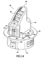
- FIG. 14 is a perspective view of connectivity system 600 according to an embodiment of the invention.
- FIG. 14 depicts certain features of connection hub 620 and grommet 610 that were not visible in FIGs. 6-9.
- connectivity system 600 comprises a retention feature 1460 comprising a slot 1461 and a slot 1462 in collar 611. Sidewalls 1463 protruding inward from interior surface 612 of collar 611 create a channel 1464. A similar channel located near slot 1461 is not visible in the drawing.
- Retention feature 1460 works with a locking feature 1470 on connection hub 620 to retain connection hub 620 in grommet 610. Retention feature 1460 and locking feature 1470 perform the stated function regardless of the orientation-whether vertical, horizontal, or an angle in between of the surface in which connection hub 620 is placed.
- Locking feature 1470 comprises a flexible tab 1471 having a raised portion 1472 capable of mating with slot 1461, and further comprises a beam 1473. A tab similar to flexible tab 1471 and a beam similar to beam 1473 are located substantially opposite flexible tab 1471 and beam 1473, but are not visible in the drawing.
- retention feature 1460 comprises only a single channel and slot
- locking feature 1470 comprises only a single flexible tab, raised portion, and beam.
- connection hub 620 To insert connection hub 620 into grommet 610, beam 1473 is aligned with the counterpart of channel 1464, the counterpart of beam 1473 is aligned with channel 1464, and connection hub 620 is inserted into grommet 610, during which process flexible tab 1471 and its counterpart flex or bend such that raised portion 1472 and its counterpart are enabled to move with respect to interior surface 612 during the insertion of connection hub 620.
- connection hub 620 reaches a certain depth within grommet 610, raised portion 1472 and its counterpart line up with slots 1461 and 1462, at which time raised portion 1472 and its counterpart relax from their flexed positions and snap into place in slots 1461 and 1462.
- Connection hub 620 is removed from grommet 610 by pressing or flexing flexible tab 1471 and its counterpart in order to remove raised portion 1472 and its counterpart from slots 1461 and 1462, thereby freeing connection hub 620 to be pulled out of grommet 610.
- FIG. 15 is a perspective view of a grommet 1510 and a cap 1520 according to an embodiment of the invention.
- grommet 1510 can be similar to grommets 210, 610, 1010, 1210 first shown, respectively, in FIGs. 2, 6, 10, and 12.
- grommet 1510 can be similar to grommet 610 as it is depicted in FIG. 14, in that grommet 1510 comprises a retention feature 1560 with a slot 1561 that are similar to, respectively, retention feature 1460 and slot 1461 of FIG. 14.
- Grommet 1510 also comprises a lip 1536.
- Cap 1520 is capable of being inserted into grommet 1510. As an example, cap 1520 can be inserted in grommet 1510 when no connection hub is occupying grommet 1510. Among other advantages, cap 1520 can give a finished look to a surface of a desk in which grommet 1510 is inserted.
- Cap 1520 comprises a locking arm 1521 having thereon a protrusion 1522 that is capable of mating with slot 1561 in a manner that is similar to the mating of slot 1461 and raised portion 1472 of flexible tab 1471 as described in connection with FIG. 14.
- cap 1520 further comprises an access hole 1523 to enable the passage of cables or other items through grommet 1510 even when cap 1520 is in place in grommet 1510.
- Grommet 1510 further comprises a flexible slat 1511 having a ledge 1512 protruding therefrom. Ledge 1512 is in physical contact with aperture 120 (see FIG. 1) when grommet 1510 is located in aperture 120.
- grommet 1510 also comprises a flexible slat 1514 with a ledge 1516 and a flexible slat 1517 with a ledge 1518. A second grouping of three, or another number, of flexible slats is located substantially opposite flexible slat 1511 on grommet 1510.
- Flexible slats 1511, 1514, and 1517 are bounded above and below by cuts 1513 that separate the flexible slats from the material of grommet 1510, thereby adding to the flexibility of the slats.
- This flexibility enables ledges 1512, 1516, and 1518 to move inward slightly when grommet 1510 is being inserted into or removed from aperture 120 (see FIG. 1), and to snap outward again when clear of aperture 120.
- This insertion and removal process works in a manner similar to the process described in connection with FIG. 14 regarding the insertion of connection hub 620 into grommet 610.
- grommet 1510 is capable of being locked into desks having surfaces of various thicknesses.
- ledge 1518 will snap outward and engage surface 901 of desk 199 when desk 199 has a surface thickness substantially equal to a distance 1570 between lip 1536 and a top 1519 of ledge 1518.
- Grommet 1510 may be removed from aperture 120 by pressing on flexible slat 1517 so as to force ledge 1518 away from surface 901 and back into aperture 120, after which grommet 1510 may be pulled out of aperture 120. If desk 199 has a thickness somewhat less than distance 1570, ledge 1518 will extend out beyond surface 901, and ledge 1516 will engage surface 901.
- ledges 1518 and 1516 will both extend out beyond surface 901, and ledge 1512 will engage surface 901. Even if desk 199 has a thickness that does not allow for one of ledges 1512, 1516, or 1518 to engage surface 901 as described, one or more of ledges 1512, 1516, and 1518 will still engage aperture 120, thereby creating friction that will help keep grommet 1510 in aperture 120.
- FIG. 16 is a perspective view of a connectivity system 1600 according to an embodiment of the invention.
- Connectivity system 1600 is similar in many respects to connectivity system 100, first shown in FIG. 1.
- connectivity system 1600 comprises a grommet 1610 capable of being inserted into aperture 120 (see FIG. 1), and a connection hub 1620 capable of being inserted into grommet 1610.
- Grommet 1610 comprises a collar 1611 having an interior surface 1612 and a lip 1616.
- Connection hub 1620 comprises a connection port 1621, a connection port 1631, a connection port 1641, and a perimeter 1622.
- Connection hub 1620 further comprises a surface 1627 on which connection port 1621 is located.
- grommet 1610, collar 1611, interior surface 1612, lip 1616, and perimeter 1622 can be similar to, respectively, grommet 210, collar 211, interior surface 212, lip 216, and perimeter 222, all of which were first shown in FIG. 2.
- surface 1627 is similar to surface 627, first shown in FIG. 6, in that surface 1627 is angled 1616.
- connection ports 1621 and 1631 comprise a first type of connection port, such as a USB or a FireWire port, and connection port 1641 comprises an AC power outlet.
- connection port 1641 comprises an AC power outlet.
- FIG. 17 is a flow chart illustrating a method 1700 of assembling a connectivity system capable of use with a desk having a surface containing an aperture according to an embodiment of the invention.
- a step 1710 of method 1700 is to provide a grommet capable of being inserted into the aperture, where the grommet comprises a collar having an interior surface.
- the connectivity system can be similar to one or more of connectivity systems 100, 600, and 1000. More specifically, the desk, the surface, and the aperture can be similar to, respectively, desk 199, surface 110, and aperture 120, all of which were first shown in FIG. 1.
- the grommet, the collar, and the interior surface can be similar to, respectively, grommet 210, collar 211, and interior surface 212, all of which were first shown in FIG. 2.
- a step 1720 of method 1700 is to provide a connection hub capable of being inserted into the grommet, where the connection hub comprises a connection port, a perimeter, and an electric cable electrically coupled to the connection port.
- the connection hub can be similar to connection hub 220, first shown in FIG. 2. More specifically, the connection port, the perimeter, and the electric cable can be similar to, respectively, connection port 221, perimeter 222, and electric cable 223, all of which were first shown in FIG. 2.
- a step 1730 of method 1700 is to insert the connection hub into the grommet such that a portion of the perimeter of the connection hub is spaced apart from the interior surface of the grommet so as to form a passageway between the portion of the perimeter of the connection hub and the interior surface of the grommet.
- the passageway can be similar to one or more of passageways 310, 710, 720, 1070, 1080, and 1270, first shown in FIGs. 3, 7, 7, 10, 10, and 12, respectively.
- embodiments and limitations disclosed herein are not dedicated to the public under the doctrine of dedication if the embodiments and/or limitations: (1) are not expressly claimed in the claims; and (2) are or are potentially equivalents of express elements and/or limitations in the claims under the doctrine of equivalents.
Landscapes
- Engineering & Computer Science (AREA)
- Architecture (AREA)
- Civil Engineering (AREA)
- Structural Engineering (AREA)
- Installation Of Indoor Wiring (AREA)
- Tables And Desks Characterized By Structural Shape (AREA)
Priority Applications (2)
| Application Number | Priority Date | Filing Date | Title |
|---|---|---|---|
| EP09171247A EP2131464A1 (fr) | 2005-05-11 | 2006-05-11 | USB hub intégré à un bureau et système de connectivité |
| EP10177274A EP2256886A2 (fr) | 2005-05-11 | 2006-05-11 | USB hub intégré à un bureau et système de connectivité |
Applications Claiming Priority (1)
| Application Number | Priority Date | Filing Date | Title |
|---|---|---|---|
| US11/127,336 US20060258195A1 (en) | 2005-05-11 | 2005-05-11 | Connectivity system, method of assembling same, and desk containing same |
Related Child Applications (1)
| Application Number | Title | Priority Date | Filing Date |
|---|---|---|---|
| EP09171247A Division EP2131464A1 (fr) | 2005-05-11 | 2006-05-11 | USB hub intégré à un bureau et système de connectivité |
Publications (2)
| Publication Number | Publication Date |
|---|---|
| EP1722452A2 true EP1722452A2 (fr) | 2006-11-15 |
| EP1722452A3 EP1722452A3 (fr) | 2008-03-05 |
Family
ID=36649053
Family Applications (3)
| Application Number | Title | Priority Date | Filing Date |
|---|---|---|---|
| EP06252473A Withdrawn EP1722452A3 (fr) | 2005-05-11 | 2006-05-11 | Système de liaison, méthode d'assemblage de ce système, et bureau contenant un tel système |
| EP10177274A Withdrawn EP2256886A2 (fr) | 2005-05-11 | 2006-05-11 | USB hub intégré à un bureau et système de connectivité |
| EP09171247A Withdrawn EP2131464A1 (fr) | 2005-05-11 | 2006-05-11 | USB hub intégré à un bureau et système de connectivité |
Family Applications After (2)
| Application Number | Title | Priority Date | Filing Date |
|---|---|---|---|
| EP10177274A Withdrawn EP2256886A2 (fr) | 2005-05-11 | 2006-05-11 | USB hub intégré à un bureau et système de connectivité |
| EP09171247A Withdrawn EP2131464A1 (fr) | 2005-05-11 | 2006-05-11 | USB hub intégré à un bureau et système de connectivité |
Country Status (2)
| Country | Link |
|---|---|
| US (3) | US20060258195A1 (fr) |
| EP (3) | EP1722452A3 (fr) |
Cited By (2)
| Publication number | Priority date | Publication date | Assignee | Title |
|---|---|---|---|---|
| USD610435S1 (en) * | 2007-10-12 | 2010-02-23 | Ameriwood Industries | Insert for a ready-to-assemble furniture grommet |
| EP1942567A3 (fr) * | 2007-01-05 | 2011-04-20 | Belkin International, Inc. | Dispositif de passe-fil électrique |
Families Citing this family (39)
| Publication number | Priority date | Publication date | Assignee | Title |
|---|---|---|---|---|
| USD588904S1 (en) * | 2007-01-03 | 2009-03-24 | Belkin International, Inc. | Grommet hub |
| USD588442S1 (en) * | 2007-01-05 | 2009-03-17 | Belkin International, Inc. | Grommet hub |
| USD568724S1 (en) * | 2007-07-26 | 2008-05-13 | Ameriwood Industries | Insert for a ready-to-assemble furniture grommet |
| USD590236S1 (en) * | 2007-10-12 | 2009-04-14 | Ameriwood Industries | Insert for a ready-to-assemble furniture grommet |
| USD592488S1 (en) * | 2007-10-12 | 2009-05-19 | Ameriwood Industries | Insert for a ready-to-assemble furniture grommet |
| USD592040S1 (en) * | 2007-10-12 | 2009-05-12 | Ameriwood Industries | Insert for a ready-to-assemble furniture grommet |
| USD592937S1 (en) * | 2007-10-12 | 2009-05-26 | Ameriwood Industries | Insert for a ready-to-assemble furniture grommet |
| USD575140S1 (en) * | 2007-10-12 | 2008-08-19 | Ameriwood Industries | Insert for a ready-to-assemble furniture grommet |
| AU2011205067B2 (en) * | 2007-12-11 | 2014-08-21 | Rheem Australia Pty Limited | An External Power Point Arrangement |
| US20140035363A1 (en) * | 2009-09-25 | 2014-02-06 | Pucline, Llc | Electrical power supplying device having a central power-receptacle assembly supplying electrical power to power plugs, adaptors and modules while concealed from view and managing excess power cord during power supplying operations |
| US8651460B2 (en) | 2011-06-01 | 2014-02-18 | The Wiremold Company | Wall grommet for power connection |
| TWM419313U (en) * | 2011-07-05 | 2011-12-21 | Arcadyan Technology Corp | Universal serial bus socket |
| US20130045135A1 (en) * | 2011-08-17 | 2013-02-21 | Symmetry Medical Manufacturing, Inc. | Grommet Device with Pull-Tab and Associated Methods Thereof |
| CN203135506U (zh) * | 2013-03-12 | 2013-08-14 | 白明远 | 办公桌嵌入式充电器 |
| USD714726S1 (en) | 2013-04-15 | 2014-10-07 | Daniel P. Byrne | Electrical power unit for a work surface |
| USD717732S1 (en) | 2013-04-15 | 2014-11-18 | Daniel P. Byrne | Electrical power unit for a work surface |
| USD736159S1 (en) | 2013-04-15 | 2015-08-11 | Daniel P. Byrne | Electrical power unit for a work surface |
| CA2910659C (fr) | 2013-05-02 | 2016-04-12 | Norman R. Byrne | Systeme de couvercle interchangeable |
| US9148006B2 (en) | 2013-05-03 | 2015-09-29 | Norman R. Byrne | Interchangeable base system |
| US9927837B2 (en) | 2013-07-03 | 2018-03-27 | Pucline, Llc | Electrical power supplying system having an electrical power supplying docking station with a multi-function module for use in diverse environments |
| CA159068S (en) | 2014-04-15 | 2015-07-08 | Norman R Byrne | Electrical power center for a work surface |
| CA2890940C (fr) | 2014-05-09 | 2017-04-25 | Norman R. Byrne | Dispositif de prise electrique dote d'un logement |
| USD741266S1 (en) | 2014-08-21 | 2015-10-20 | Norman R. Byrne | Electrical power unit for a work surface |
| USD761732S1 (en) | 2015-02-06 | 2016-07-19 | Norman R. Byrne | Electrical power unit |
| USD762175S1 (en) | 2015-02-06 | 2016-07-26 | Norman R. Byrne | Electrical power unit for a work surface |
| USD762176S1 (en) | 2015-03-06 | 2016-07-26 | Norman R. Byrne | Electrical power unit for a work surface |
| US10181735B2 (en) | 2015-03-11 | 2019-01-15 | Norman R. Byrne | Portable electrical power unit |
| US9748709B2 (en) * | 2015-03-31 | 2017-08-29 | Norman R. Byrne | Grommet-mount electrical power unit assembly |
| USD775936S1 (en) * | 2015-06-17 | 2017-01-10 | Brandon Barnard | Cable management station |
| CA2960239A1 (fr) | 2016-03-11 | 2017-09-11 | Norman R. Byrne | Poste de recharge fixe a un meuble |
| US10587104B2 (en) * | 2017-02-02 | 2020-03-10 | Brian Fried | Locking grommet system and method |
| USD848371S1 (en) | 2017-05-17 | 2019-05-14 | Daniel P. Byrne | Electrical power unit for a work surface |
| US10367317B1 (en) * | 2017-06-12 | 2019-07-30 | Premier Manufacturing Group, Inc. | Portable electric power hub with AC power receptacles and USB charging ports |
| MX387762B (es) | 2017-07-24 | 2025-03-18 | Norman R Byrne | Estacion de carga electrica montada en muebles |
| US10566806B2 (en) * | 2017-11-08 | 2020-02-18 | Todd Adam | Multi-device tabletop charging station |
| USD887363S1 (en) | 2018-01-24 | 2020-06-16 | Norman R. Byrne | Electrical power unit |
| USD900035S1 (en) | 2018-06-08 | 2020-10-27 | Norman R. Byrne | Electrical power grommet for a worksurface |
| USD905644S1 (en) | 2019-03-29 | 2020-12-22 | Norman R. Byrne | Electrical power grommet for a work surface |
| USD954653S1 (en) | 2019-11-13 | 2022-06-14 | Norman R. Byrne | Electrical power unit for a work surface |
Family Cites Families (97)
| Publication number | Priority date | Publication date | Assignee | Title |
|---|---|---|---|---|
| US4401351A (en) * | 1981-09-28 | 1983-08-30 | Advant Corporation | Expandable card cage |
| JPS58117023U (ja) * | 1982-02-03 | 1983-08-10 | 株式会社 サン電業社 | スイツチ等の取付装置 |
| US4501460A (en) * | 1983-05-09 | 1985-02-26 | Convergent Technologies, Inc. | Modular housing for computer system |
| FR2580136B1 (fr) * | 1985-04-05 | 1988-10-14 | Radiotechnique Compelec | |
| USD301713S (en) * | 1985-10-30 | 1989-06-20 | Dallas Semiconductor Corporation | Portable memory module |
| US4688491A (en) * | 1986-09-08 | 1987-08-25 | Allsteel Inc. | Grommet arrangement for office furniture desk tops |
| US4850484A (en) * | 1986-11-13 | 1989-07-25 | Denman Dennis L | Accessory for livestock injection operations |
| US4845589A (en) * | 1987-05-04 | 1989-07-04 | Amp Incorporated | Bus bar connector assembly |
| US4864078A (en) * | 1988-05-09 | 1989-09-05 | Bowman Timothy S | Activation kits for presets |
| USD313340S (en) * | 1988-07-05 | 1991-01-01 | Doug Mockett and Company, Inc. | Cord access grommet set for office furniture use |
| US5030128A (en) * | 1989-03-06 | 1991-07-09 | Dynabook Technologies Corporation | Docking module |
| US5231562A (en) * | 1991-01-02 | 1993-07-27 | Lawrence Pierce | Desk top wire management apparatus |
| US5144777A (en) * | 1991-04-09 | 1992-09-08 | Allsteel Inc. | Grommet assembly for wall panels |
| US5301346A (en) * | 1991-06-21 | 1994-04-05 | Cad Forms Technology Inc. | Method and apparatus for transferring data between a host device and plurality of portable computers |
| US5247406A (en) * | 1991-07-30 | 1993-09-21 | Storage Technology Corporation | Tape cartridge magazine |
| US5483419A (en) * | 1991-09-24 | 1996-01-09 | Teac Corporation | Hot-swappable multi-cartridge docking module |
| US5333097A (en) * | 1992-06-18 | 1994-07-26 | Digital Equipment Corporation | Disk drive holder and interconnection system |
| US6640235B1 (en) * | 1992-08-20 | 2003-10-28 | Intel Corporation | Expandable mass disk drive storage system |
| USD350944S (en) * | 1993-03-08 | 1994-09-27 | Micropolis Corporation | Expandable modular disk drive array |
| JP2991886B2 (ja) * | 1993-03-09 | 1999-12-20 | 富士通株式会社 | 電子交換機システムのシェルフアセンブリ |
| US5336102A (en) * | 1993-06-07 | 1994-08-09 | Ford Motor Company | Connector interface seal |
| USD354903S (en) * | 1993-12-20 | 1995-01-31 | Doug Mockett & Company, Inc. | Grommet with pivoting tab |
| US5726922A (en) * | 1994-01-03 | 1998-03-10 | International Business Machines Corp. | Assembly for removably connecting data storage devices |
| US5737189A (en) * | 1994-01-10 | 1998-04-07 | Artecon | High performance mass storage subsystem |
| US5440181A (en) * | 1994-01-31 | 1995-08-08 | Motorola, Inc. | Configuration circuit for configuring a multi-board system automatically |
| USD355416S (en) * | 1994-02-14 | 1995-02-14 | Coherent Communications Systems Corporation | Transceiver module for a table-top teleconferencing system |
| US5515239A (en) * | 1994-02-18 | 1996-05-07 | Quantum Corporation | Stackable modular storage tower |
| JPH10500248A (ja) * | 1994-05-10 | 1998-01-06 | バーグ・テクノロジー・インコーポレーテッド | 多連釣針状ホールドダウン |
| USD358980S (en) * | 1994-06-27 | 1995-06-06 | Doug Mockett & Company, Inc. | Grommet with pivoting tab |
| USD362663S (en) * | 1994-08-19 | 1995-09-26 | Alps Electric (Usa) Inc. | Docking station for a pen computer |
| US5498174A (en) * | 1994-10-18 | 1996-03-12 | The Whitaker Corporation | Electrical connector with spring leg retention feature |
| USD366455S (en) * | 1994-11-09 | 1996-01-23 | D-Link Corporation | Portable hub |
| JP3305154B2 (ja) * | 1995-03-28 | 2002-07-22 | ナイルス部品株式会社 | 回転コネクタ装置に於けるハウジング構造 |
| US5777845A (en) * | 1995-05-24 | 1998-07-07 | Seagate Technology, Inc. | High density redundant array of independent disks in a chassis having a door with shock absorbers held against the disks when the door is closed |
| USD379972S (en) * | 1995-08-09 | 1997-06-17 | La Cie, Ltd. | Stackable storage device tower assembly of selectable height |
| US5645434A (en) * | 1995-12-01 | 1997-07-08 | Asante Technologies, Inc. | Connector element and component arrangement for a stackable communications network hub |
| US5673172A (en) * | 1996-01-05 | 1997-09-30 | Compaq Computer Corporation | Apparatus for electromagnetic interference and electrostatic discharge shielding of hot plug-connected hard disk drives |
| US5706179A (en) * | 1996-02-07 | 1998-01-06 | Palatov; Dennis | Computer housing and expansion card format for consumer electronics devices |
| USD393451S (en) * | 1996-03-13 | 1998-04-14 | Digital Equipment Corporation | Portable multimedia docking module |
| US6076142A (en) * | 1996-03-15 | 2000-06-13 | Ampex Corporation | User configurable raid system with multiple data bus segments and removable electrical bridges |
| US5692400A (en) * | 1996-03-25 | 1997-12-02 | Hewlett-Packard Company | Securing portable computers and associated docking systems |
| US6018456A (en) * | 1996-05-31 | 2000-01-25 | Cmd Technology, Inc. | Enclosure for removable computer peripheral equipment |
| US6609928B1 (en) * | 1996-06-14 | 2003-08-26 | Intel Corporation | Stack universal serial bus connector |
| JP3465486B2 (ja) * | 1996-07-22 | 2003-11-10 | ミツミ電機株式会社 | 電気コネクタ |
| US5875094A (en) * | 1996-08-02 | 1999-02-23 | Compaq Computer Corporation | Portable computer docking station with adjustable insertion angle |
| US5765932A (en) * | 1996-08-07 | 1998-06-16 | Steelcase Inc. | Utility grommet |
| US6042426A (en) * | 1996-11-13 | 2000-03-28 | Byrne; Norman R. | Multi-user electrical services outlet |
| US5871368A (en) * | 1996-11-19 | 1999-02-16 | Intel Corporation | Bus connector |
| US5896273A (en) * | 1996-12-31 | 1999-04-20 | Compaq Computer Corp. | Modular computer chassis interchangeable between stand alone and rack mounted states |
| USD391944S (en) * | 1997-01-22 | 1998-03-10 | Microsoft Corporation | Computer output device |
| USD392147S (en) * | 1997-04-04 | 1998-03-17 | Qualstar Corporation | Simplified tape cartridge rack |
| USD406102S (en) * | 1997-06-05 | 1999-02-23 | Byrne Norman R | Double lift up device |
| USD408012S (en) * | 1997-06-27 | 1999-04-13 | The Whitaker Corporation | Hub |
| US6073188A (en) * | 1997-07-25 | 2000-06-06 | Compaq Computer Corporation | Electronic switchbox for selection and sharing of internal peripheral devices among different computers, the internal peripheral devices located in slots of a chassis |
| TW347105U (en) * | 1997-09-19 | 1998-12-01 | Mitac Int Corp | Integrated-type computer |
| US5956267A (en) * | 1997-12-18 | 1999-09-21 | Honeywell Inc | Self-aligned wordline keeper and method of manufacture therefor |
| USD412494S (en) * | 1997-12-26 | 1999-08-03 | Sharp Kabushiki Kaisha | Electronic computer with docking station |
| US6254427B1 (en) * | 1998-01-07 | 2001-07-03 | Doug Mockett & Company, Inc. | Power and communications grommet |
| US6024599A (en) * | 1998-01-07 | 2000-02-15 | Doug Mockett & Company, Inc. | Power and communications grommet |
| US6233782B1 (en) * | 1998-01-20 | 2001-05-22 | Stephen Matthew Regele | Fastener grommet |
| USD422267S (en) * | 1998-03-05 | 2000-04-04 | Motorola, Inc. | Housing for an accessory connector |
| USD413893S (en) * | 1998-03-18 | 1999-09-14 | Motorola, Inc. | Telephone accessory |
| USD423010S (en) * | 1998-04-23 | 2000-04-18 | Sony Corporation | Pager module |
| US6098131A (en) * | 1998-05-04 | 2000-08-01 | Nortel Networks Limited | Network apparatus with removable electronic module |
| AU701144B3 (en) * | 1998-06-29 | 1999-01-21 | Compal Electronics, Inc. | Stand having a housing adapted for supporting a liquid crystal display panel on a base, and a universal serial bus hub module mounted detachably on the housing |
| USD411989S (en) * | 1998-07-31 | 1999-07-13 | Abbott Laboratories | Docking station |
| US5940319A (en) * | 1998-08-31 | 1999-08-17 | Motorola, Inc. | Magnetic random access memory and fabricating method thereof |
| US6053278A (en) * | 1998-09-22 | 2000-04-25 | Myers; Timothy R. | Multiple use convertible elevated stand and cart |
| USD412322S (en) * | 1998-09-28 | 1999-07-27 | Commercial & Industrial Design Co., Inc. | Data port coupler |
| USD419978S (en) * | 1998-10-30 | 2000-02-01 | Mah Pat Y | Electronic support housing |
| US6052278A (en) * | 1998-11-13 | 2000-04-18 | Hewlett-Packard Company | Data storage module and enclosure system |
| US6234812B1 (en) * | 1998-11-24 | 2001-05-22 | Michael B. Ivers | Retractable power and communication outlet arrangements |
| USD425866S (en) * | 1998-12-15 | 2000-05-30 | Accton Technology Corporation | Usb hub |
| USD421962S (en) * | 1999-04-21 | 2000-03-28 | Acco Brands, Inc. | USB hub |
| USD436109S1 (en) * | 1999-08-03 | 2001-01-09 | Belkin Components | Universal serial bus module |
| WO2001042937A1 (fr) * | 1999-12-06 | 2001-06-14 | Henry Milan | Systeme modulaire de composants empilables comportant un noyau de bus seriels universels |
| USD444462S1 (en) * | 1999-12-28 | 2001-07-03 | Sharp Kabushiki Kaisha | Electronic computer |
| US6211090B1 (en) * | 2000-03-21 | 2001-04-03 | Motorola, Inc. | Method of fabricating flux concentrating layer for use with magnetoresistive random access memories |
| US6349036B1 (en) * | 2000-05-29 | 2002-02-19 | Jess-Link Products Co., Ltd. | Adaptive seat of computer functional cards |
| USD458608S1 (en) * | 2000-08-03 | 2002-06-11 | Belkin Components | Combined universal serial bus docking station and modules |
| US6551130B2 (en) * | 2001-02-09 | 2003-04-22 | Hubbell Incorporated | 4×8 fire rated poke through fitting |
| DE10122123A1 (de) * | 2001-05-07 | 2002-12-12 | Modelec Sa | Elektrische Anschlußsäule als Einschubteil |
| US6492591B1 (en) * | 2001-06-11 | 2002-12-10 | Kimball International, Inc. | Movable electrical and data services module |
| US6430085B1 (en) * | 2001-08-27 | 2002-08-06 | Motorola, Inc. | Magnetic random access memory having digit lines and bit lines with shape and induced anisotropy ferromagnetic cladding layer and method of manufacture |
| US6430084B1 (en) * | 2001-08-27 | 2002-08-06 | Motorola, Inc. | Magnetic random access memory having digit lines and bit lines with a ferromagnetic cladding layer |
| US6720597B2 (en) * | 2001-11-13 | 2004-04-13 | Motorola, Inc. | Cladding of a conductive interconnect for programming a MRAM device using multiple magnetic layers |
| USD475996S1 (en) * | 2001-11-13 | 2003-06-17 | Gerald W. Skulley | Universal serial bus interface housing for communications devices |
| US6398569B1 (en) * | 2001-11-16 | 2002-06-04 | Dell Products L.P. | Apparatus and method for unattended disconnect of plug-in connectors |
| US7167372B2 (en) * | 2003-08-26 | 2007-01-23 | Belkin Corporation | Universal serial bus hub and method of manufacturing same |
| US6722917B2 (en) * | 2002-02-01 | 2004-04-20 | Yea Yen Huang | USB hub |
| US6983341B1 (en) * | 2002-05-21 | 2006-01-03 | Adaptec, Inc. | Modular peripheral device hub |
| US7064275B2 (en) * | 2002-06-07 | 2006-06-20 | Kimball International, Inc. | Cable management device |
| US7329152B2 (en) * | 2003-08-26 | 2008-02-12 | Belkin International, Inc. | Universal serial bus hub and method of manufacturing same |
| USD500497S1 (en) * | 2003-09-26 | 2005-01-04 | Action Star Enterprise Co., Ltd. | Hub |
| US6923684B2 (en) * | 2003-10-10 | 2005-08-02 | O'sullivan Industries, Inc. | Power harness having multiple upstream USB ports |
| US7163409B1 (en) * | 2006-07-19 | 2007-01-16 | Hoolin Research Company Limited | Modular integrated socket apparatus |
| US7989738B2 (en) * | 2006-12-14 | 2011-08-02 | Byrne Norman R | Grommet assembly for warming liquids on work surface |
-
2005
- 2005-05-11 US US11/127,336 patent/US20060258195A1/en not_active Abandoned
-
2006
- 2006-05-11 EP EP06252473A patent/EP1722452A3/fr not_active Withdrawn
- 2006-05-11 EP EP10177274A patent/EP2256886A2/fr not_active Withdrawn
- 2006-05-11 EP EP09171247A patent/EP2131464A1/fr not_active Withdrawn
-
2009
- 2009-04-08 US US12/420,699 patent/US20090201634A1/en not_active Abandoned
-
2010
- 2010-08-23 US US12/861,620 patent/US20100317224A1/en not_active Abandoned
Cited By (2)
| Publication number | Priority date | Publication date | Assignee | Title |
|---|---|---|---|---|
| EP1942567A3 (fr) * | 2007-01-05 | 2011-04-20 | Belkin International, Inc. | Dispositif de passe-fil électrique |
| USD610435S1 (en) * | 2007-10-12 | 2010-02-23 | Ameriwood Industries | Insert for a ready-to-assemble furniture grommet |
Also Published As
| Publication number | Publication date |
|---|---|
| US20090201634A1 (en) | 2009-08-13 |
| US20100317224A1 (en) | 2010-12-16 |
| EP2256886A2 (fr) | 2010-12-01 |
| EP1722452A3 (fr) | 2008-03-05 |
| EP2131464A1 (fr) | 2009-12-09 |
| US20060258195A1 (en) | 2006-11-16 |
Similar Documents
| Publication | Publication Date | Title |
|---|---|---|
| EP2131464A1 (fr) | USB hub intégré à un bureau et système de connectivité | |
| EP2801287B1 (fr) | Enceinte montable en surface modulaire | |
| US7553174B2 (en) | Cable management device configured to support one or more electrical devices and methods of manufacturing and using the same | |
| US7038126B2 (en) | Cable/wire and electronic device storage container | |
| US6492591B1 (en) | Movable electrical and data services module | |
| US8882519B2 (en) | Dust cap for a telecommunications connector | |
| US9891400B2 (en) | Pivotable cover for sliding tray and sliding tray including the cover | |
| EP1916591A1 (fr) | Dispositif de gestion de câble et procédé de gestion de câble | |
| US7361050B2 (en) | Cable management device for use in connection with a power center, and cable management system comprising same | |
| EP1942567A2 (fr) | Dispositif de passe-fil électrique | |
| US20060276077A1 (en) | Electrical connectivity system capable of being mounted to an object, and method of manufacturing same | |
| US7717738B2 (en) | Power cord management attachment for use with a power socket device | |
| US6969803B1 (en) | Faceplate with storage device coupled thereto | |
| US9666980B2 (en) | Electrical power strip housing | |
| US4937400A (en) | Mounting and retaining apparatus for conductors | |
| US20190319376A1 (en) | Keyed Cable and Connector System | |
| EP1933435A2 (fr) | Dispositif de gestion de câble configuré pour supporter un ou plusieurs dispositifs et son procédé de fabrication et son utilisation | |
| CN212521120U (zh) | 一种多功能桌面 | |
| CA2999559A1 (fr) | Systeme de conduit de service public | |
| KR102788576B1 (ko) | 전선 및 멀티탭 정리함 | |
| US20130327900A1 (en) | Cable catching device | |
| KR20250024027A (ko) | 걸고리형 멀티탭 브라켓 구조물 | |
| RU199983U1 (ru) | Модуль для прикрытия и упорядочения кабелей на поверхности стола | |
| KR20240165809A (ko) | 벽면 부착형 멀티탭 브라켓 구조물 | |
| US9545021B2 (en) | Mat with cable management for electronic devices |
Legal Events
| Date | Code | Title | Description |
|---|---|---|---|
| PUAI | Public reference made under article 153(3) epc to a published international application that has entered the european phase |
Free format text: ORIGINAL CODE: 0009012 |
|
| AK | Designated contracting states |
Kind code of ref document: A2 Designated state(s): AT BE BG CH CY CZ DE DK EE ES FI FR GB GR HU IE IS IT LI LT LU LV MC NL PL PT RO SE SI SK TR |
|
| AX | Request for extension of the european patent |
Extension state: AL BA HR MK YU |
|
| RAP1 | Party data changed (applicant data changed or rights of an application transferred) |
Owner name: BELKIN INTERNATIONAL, INC |
|
| PUAL | Search report despatched |
Free format text: ORIGINAL CODE: 0009013 |
|
| AK | Designated contracting states |
Kind code of ref document: A3 Designated state(s): AT BE BG CH CY CZ DE DK EE ES FI FR GB GR HU IE IS IT LI LT LU LV MC NL PL PT RO SE SI SK TR |
|
| AX | Request for extension of the european patent |
Extension state: AL BA HR MK YU |
|
| 17P | Request for examination filed |
Effective date: 20080612 |
|
| 17Q | First examination report despatched |
Effective date: 20080710 |
|
| AKX | Designation fees paid |
Designated state(s): AT BE BG CH CY CZ DE DK EE ES FI FR GB GR HU IE IS IT LI LT LU LV MC NL PL PT RO SE SI SK TR |
|
| GRAP | Despatch of communication of intention to grant a patent |
Free format text: ORIGINAL CODE: EPIDOSNIGR1 |
|
| STAA | Information on the status of an ep patent application or granted ep patent |
Free format text: STATUS: THE APPLICATION IS DEEMED TO BE WITHDRAWN |
|
| 18D | Application deemed to be withdrawn |
Effective date: 20091008 |