EP1721365B1 - Terminal de cable a chevilles de contact a amelioration pneumatique - Google Patents
Terminal de cable a chevilles de contact a amelioration pneumatique Download PDFInfo
- Publication number
- EP1721365B1 EP1721365B1 EP05724559A EP05724559A EP1721365B1 EP 1721365 B1 EP1721365 B1 EP 1721365B1 EP 05724559 A EP05724559 A EP 05724559A EP 05724559 A EP05724559 A EP 05724559A EP 1721365 B1 EP1721365 B1 EP 1721365B1
- Authority
- EP
- European Patent Office
- Prior art keywords
- sleeve
- pin
- connector
- probes
- probe
- Prior art date
- Legal status (The legal status is an assumption and is not a legal conclusion. Google has not performed a legal analysis and makes no representation as to the accuracy of the status listed.)
- Expired - Fee Related
Links
Images


Classifications
-
- H—ELECTRICITY
- H01—ELECTRIC ELEMENTS
- H01R—ELECTRICALLY-CONDUCTIVE CONNECTIONS; STRUCTURAL ASSOCIATIONS OF A PLURALITY OF MUTUALLY-INSULATED ELECTRICAL CONNECTING ELEMENTS; COUPLING DEVICES; CURRENT COLLECTORS
- H01R11/00—Individual connecting elements providing two or more spaced connecting locations for conductive members which are, or may be, thereby interconnected, e.g. end pieces for wires or cables supported by the wire or cable and having means for facilitating electrical connection to some other wire, terminal, or conductive member, blocks of binding posts
- H01R11/11—End pieces or tapping pieces for wires, supported by the wire and for facilitating electrical connection to some other wire, terminal or conductive member
- H01R11/18—End pieces terminating in a probe
-
- G—PHYSICS
- G01—MEASURING; TESTING
- G01R—MEASURING ELECTRIC VARIABLES; MEASURING MAGNETIC VARIABLES
- G01R1/00—Details of instruments or arrangements of the types included in groups G01R5/00 - G01R13/00 and G01R31/00
- G01R1/02—General constructional details
- G01R1/04—Housings; Supporting members; Arrangements of terminals
- G01R1/0408—Test fixtures or contact fields; Connectors or connecting adaptors; Test clips; Test sockets
- G01R1/0416—Connectors, terminals
-
- G—PHYSICS
- G01—MEASURING; TESTING
- G01R—MEASURING ELECTRIC VARIABLES; MEASURING MAGNETIC VARIABLES
- G01R1/00—Details of instruments or arrangements of the types included in groups G01R5/00 - G01R13/00 and G01R31/00
- G01R1/02—General constructional details
- G01R1/06—Measuring leads; Measuring probes
- G01R1/067—Measuring probes
- G01R1/06772—High frequency probes
-
- H—ELECTRICITY
- H01—ELECTRIC ELEMENTS
- H01R—ELECTRICALLY-CONDUCTIVE CONNECTIONS; STRUCTURAL ASSOCIATIONS OF A PLURALITY OF MUTUALLY-INSULATED ELECTRICAL CONNECTING ELEMENTS; COUPLING DEVICES; CURRENT COLLECTORS
- H01R12/00—Structural associations of a plurality of mutually-insulated electrical connecting elements, specially adapted for printed circuits, e.g. printed circuit boards [PCB], flat or ribbon cables, or like generally planar structures, e.g. terminal strips, terminal blocks; Coupling devices specially adapted for printed circuits, flat or ribbon cables, or like generally planar structures; Terminals specially adapted for contact with, or insertion into, printed circuits, flat or ribbon cables, or like generally planar structures
- H01R12/50—Fixed connections
- H01R12/51—Fixed connections for rigid printed circuits or like structures
- H01R12/55—Fixed connections for rigid printed circuits or like structures characterised by the terminals
- H01R12/57—Fixed connections for rigid printed circuits or like structures characterised by the terminals surface mounting terminals
-
- H—ELECTRICITY
- H01—ELECTRIC ELEMENTS
- H01R—ELECTRICALLY-CONDUCTIVE CONNECTIONS; STRUCTURAL ASSOCIATIONS OF A PLURALITY OF MUTUALLY-INSULATED ELECTRICAL CONNECTING ELEMENTS; COUPLING DEVICES; CURRENT COLLECTORS
- H01R12/00—Structural associations of a plurality of mutually-insulated electrical connecting elements, specially adapted for printed circuits, e.g. printed circuit boards [PCB], flat or ribbon cables, or like generally planar structures, e.g. terminal strips, terminal blocks; Coupling devices specially adapted for printed circuits, flat or ribbon cables, or like generally planar structures; Terminals specially adapted for contact with, or insertion into, printed circuits, flat or ribbon cables, or like generally planar structures
- H01R12/50—Fixed connections
- H01R12/59—Fixed connections for flexible printed circuits, flat or ribbon cables or like structures
- H01R12/594—Fixed connections for flexible printed circuits, flat or ribbon cables or like structures for shielded flat cable
- H01R12/598—Each conductor being individually surrounded by shield, e.g. multiple coaxial cables in flat structure
-
- H—ELECTRICITY
- H01—ELECTRIC ELEMENTS
- H01R—ELECTRICALLY-CONDUCTIVE CONNECTIONS; STRUCTURAL ASSOCIATIONS OF A PLURALITY OF MUTUALLY-INSULATED ELECTRICAL CONNECTING ELEMENTS; COUPLING DEVICES; CURRENT COLLECTORS
- H01R12/00—Structural associations of a plurality of mutually-insulated electrical connecting elements, specially adapted for printed circuits, e.g. printed circuit boards [PCB], flat or ribbon cables, or like generally planar structures, e.g. terminal strips, terminal blocks; Coupling devices specially adapted for printed circuits, flat or ribbon cables, or like generally planar structures; Terminals specially adapted for contact with, or insertion into, printed circuits, flat or ribbon cables, or like generally planar structures
- H01R12/50—Fixed connections
- H01R12/59—Fixed connections for flexible printed circuits, flat or ribbon cables or like structures
- H01R12/61—Fixed connections for flexible printed circuits, flat or ribbon cables or like structures connecting to flexible printed circuits, flat or ribbon cables or like structures
-
- H—ELECTRICITY
- H01—ELECTRIC ELEMENTS
- H01R—ELECTRICALLY-CONDUCTIVE CONNECTIONS; STRUCTURAL ASSOCIATIONS OF A PLURALITY OF MUTUALLY-INSULATED ELECTRICAL CONNECTING ELEMENTS; COUPLING DEVICES; CURRENT COLLECTORS
- H01R13/00—Details of coupling devices of the kinds covered by groups H01R12/70 or H01R24/00 - H01R33/00
- H01R13/66—Structural association with built-in electrical component
-
- H—ELECTRICITY
- H01—ELECTRIC ELEMENTS
- H01R—ELECTRICALLY-CONDUCTIVE CONNECTIONS; STRUCTURAL ASSOCIATIONS OF A PLURALITY OF MUTUALLY-INSULATED ELECTRICAL CONNECTING ELEMENTS; COUPLING DEVICES; CURRENT COLLECTORS
- H01R24/00—Two-part coupling devices, or either of their cooperating parts, characterised by their overall structure
- H01R24/38—Two-part coupling devices, or either of their cooperating parts, characterised by their overall structure having concentrically or coaxially arranged contacts
- H01R24/40—Two-part coupling devices, or either of their cooperating parts, characterised by their overall structure having concentrically or coaxially arranged contacts specially adapted for high frequency
- H01R24/42—Two-part coupling devices, or either of their cooperating parts, characterised by their overall structure having concentrically or coaxially arranged contacts specially adapted for high frequency comprising impedance matching means or electrical components, e.g. filters or switches
- H01R24/44—Two-part coupling devices, or either of their cooperating parts, characterised by their overall structure having concentrically or coaxially arranged contacts specially adapted for high frequency comprising impedance matching means or electrical components, e.g. filters or switches comprising impedance matching means
-
- H—ELECTRICITY
- H01—ELECTRIC ELEMENTS
- H01R—ELECTRICALLY-CONDUCTIVE CONNECTIONS; STRUCTURAL ASSOCIATIONS OF A PLURALITY OF MUTUALLY-INSULATED ELECTRICAL CONNECTING ELEMENTS; COUPLING DEVICES; CURRENT COLLECTORS
- H01R9/00—Structural associations of a plurality of mutually-insulated electrical connecting elements, e.g. terminal strips or terminal blocks; Terminals or binding posts mounted upon a base or in a case; Bases therefor
- H01R9/03—Connectors arranged to contact a plurality of the conductors of a multiconductor cable, e.g. tapping connections
- H01R9/05—Connectors arranged to contact a plurality of the conductors of a multiconductor cable, e.g. tapping connections for coaxial cables
- H01R9/0515—Connection to a rigid planar substrate, e.g. printed circuit board
-
- G—PHYSICS
- G01—MEASURING; TESTING
- G01R—MEASURING ELECTRIC VARIABLES; MEASURING MAGNETIC VARIABLES
- G01R1/00—Details of instruments or arrangements of the types included in groups G01R5/00 - G01R13/00 and G01R31/00
- G01R1/02—General constructional details
- G01R1/06—Measuring leads; Measuring probes
- G01R1/067—Measuring probes
- G01R1/06711—Probe needles; Cantilever beams; "Bump" contacts; Replaceable probe pins
- G01R1/06716—Elastic
- G01R1/06722—Spring-loaded
-
- H—ELECTRICITY
- H01—ELECTRIC ELEMENTS
- H01R—ELECTRICALLY-CONDUCTIVE CONNECTIONS; STRUCTURAL ASSOCIATIONS OF A PLURALITY OF MUTUALLY-INSULATED ELECTRICAL CONNECTING ELEMENTS; COUPLING DEVICES; CURRENT COLLECTORS
- H01R12/00—Structural associations of a plurality of mutually-insulated electrical connecting elements, specially adapted for printed circuits, e.g. printed circuit boards [PCB], flat or ribbon cables, or like generally planar structures, e.g. terminal strips, terminal blocks; Coupling devices specially adapted for printed circuits, flat or ribbon cables, or like generally planar structures; Terminals specially adapted for contact with, or insertion into, printed circuits, flat or ribbon cables, or like generally planar structures
- H01R12/50—Fixed connections
- H01R12/59—Fixed connections for flexible printed circuits, flat or ribbon cables or like structures
- H01R12/592—Fixed connections for flexible printed circuits, flat or ribbon cables or like structures connections to contact elements
-
- H—ELECTRICITY
- H01—ELECTRIC ELEMENTS
- H01R—ELECTRICALLY-CONDUCTIVE CONNECTIONS; STRUCTURAL ASSOCIATIONS OF A PLURALITY OF MUTUALLY-INSULATED ELECTRICAL CONNECTING ELEMENTS; COUPLING DEVICES; CURRENT COLLECTORS
- H01R12/00—Structural associations of a plurality of mutually-insulated electrical connecting elements, specially adapted for printed circuits, e.g. printed circuit boards [PCB], flat or ribbon cables, or like generally planar structures, e.g. terminal strips, terminal blocks; Coupling devices specially adapted for printed circuits, flat or ribbon cables, or like generally planar structures; Terminals specially adapted for contact with, or insertion into, printed circuits, flat or ribbon cables, or like generally planar structures
- H01R12/50—Fixed connections
- H01R12/59—Fixed connections for flexible printed circuits, flat or ribbon cables or like structures
- H01R12/62—Fixed connections for flexible printed circuits, flat or ribbon cables or like structures connecting to rigid printed circuits or like structures
-
- H—ELECTRICITY
- H01—ELECTRIC ELEMENTS
- H01R—ELECTRICALLY-CONDUCTIVE CONNECTIONS; STRUCTURAL ASSOCIATIONS OF A PLURALITY OF MUTUALLY-INSULATED ELECTRICAL CONNECTING ELEMENTS; COUPLING DEVICES; CURRENT COLLECTORS
- H01R13/00—Details of coupling devices of the kinds covered by groups H01R12/70 or H01R24/00 - H01R33/00
- H01R13/46—Bases; Cases
- H01R13/502—Bases; Cases composed of different pieces
- H01R13/512—Bases; Cases composed of different pieces assembled by screw or screws
-
- H—ELECTRICITY
- H01—ELECTRIC ELEMENTS
- H01R—ELECTRICALLY-CONDUCTIVE CONNECTIONS; STRUCTURAL ASSOCIATIONS OF A PLURALITY OF MUTUALLY-INSULATED ELECTRICAL CONNECTING ELEMENTS; COUPLING DEVICES; CURRENT COLLECTORS
- H01R13/00—Details of coupling devices of the kinds covered by groups H01R12/70 or H01R24/00 - H01R33/00
- H01R13/66—Structural association with built-in electrical component
- H01R13/6608—Structural association with built-in electrical component with built-in single component
- H01R13/6616—Structural association with built-in electrical component with built-in single component with resistor
-
- H—ELECTRICITY
- H01—ELECTRIC ELEMENTS
- H01R—ELECTRICALLY-CONDUCTIVE CONNECTIONS; STRUCTURAL ASSOCIATIONS OF A PLURALITY OF MUTUALLY-INSULATED ELECTRICAL CONNECTING ELEMENTS; COUPLING DEVICES; CURRENT COLLECTORS
- H01R13/00—Details of coupling devices of the kinds covered by groups H01R12/70 or H01R24/00 - H01R33/00
- H01R13/66—Structural association with built-in electrical component
- H01R13/6608—Structural association with built-in electrical component with built-in single component
- H01R13/6625—Structural association with built-in electrical component with built-in single component with capacitive component
-
- H—ELECTRICITY
- H01—ELECTRIC ELEMENTS
- H01R—ELECTRICALLY-CONDUCTIVE CONNECTIONS; STRUCTURAL ASSOCIATIONS OF A PLURALITY OF MUTUALLY-INSULATED ELECTRICAL CONNECTING ELEMENTS; COUPLING DEVICES; CURRENT COLLECTORS
- H01R13/00—Details of coupling devices of the kinds covered by groups H01R12/70 or H01R24/00 - H01R33/00
- H01R13/66—Structural association with built-in electrical component
- H01R13/665—Structural association with built-in electrical component with built-in electronic circuit
-
- H—ELECTRICITY
- H01—ELECTRIC ELEMENTS
- H01R—ELECTRICALLY-CONDUCTIVE CONNECTIONS; STRUCTURAL ASSOCIATIONS OF A PLURALITY OF MUTUALLY-INSULATED ELECTRICAL CONNECTING ELEMENTS; COUPLING DEVICES; CURRENT COLLECTORS
- H01R2103/00—Two poles
-
- H—ELECTRICITY
- H01—ELECTRIC ELEMENTS
- H01R—ELECTRICALLY-CONDUCTIVE CONNECTIONS; STRUCTURAL ASSOCIATIONS OF A PLURALITY OF MUTUALLY-INSULATED ELECTRICAL CONNECTING ELEMENTS; COUPLING DEVICES; CURRENT COLLECTORS
- H01R2201/00—Connectors or connections adapted for particular applications
- H01R2201/20—Connectors or connections adapted for particular applications for testing or measuring purposes
Landscapes
- Physics & Mathematics (AREA)
- General Physics & Mathematics (AREA)
- Measuring Leads Or Probes (AREA)
- Shielding Devices Or Components To Electric Or Magnetic Fields (AREA)
- Details Of Connecting Devices For Male And Female Coupling (AREA)
Abstract
Claims (14)
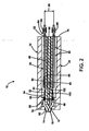
- Connecteur électrique, comprenant:un corps (202);plusieurs sondes (204) connectées au corps (202) ;chaque sonde (204) comportant une broche poussée par ressort (256), avec une pointe de contact (272) ;chaque sonde (204) englobant une partie de douille (254) recevant la broche (256) ; etchaque partie de douille (254) comportant une première extrémité (260), une deuxième extrémité (262) connectée au corps (202), et à partir de laquelle la broche (256) déborde, et une partie intermédiaire suspendue hors de contact avec le corps (202), caractérisé par :plusieurs câbles coaxiaux (206) connectés au corps (202), chaque câble (206) comportant un conducteur de signaux (240) entouré par un blindage conducteur (234), les sondes (204) étant agencées dans un réseau, la première extrémité (260) de la partie de douille (254) de chaque deuxième sonde étant connectée à un conducteur de signaux d'entrée respectif (240), et les sondes restantes étant connectées aux blindages (234).
- Connecteur selon la revendication 1, dans lequel chaque partie de douille (254) est espacée des parties de douille adjacentes, sans matériau intermédiaire.
- Connecteur selon les revendications 1 ou 2, dans lequel la partie intermédiaire de chaque partie de douille (254) est suspendue dans l'air, chaque partie de douille (254) étant espacée des parties de douille adjacentes.
- Connecteur selon l'une quelconque des revendications précédentes, dans lequel les premières extrémités des parties de douille (254) des douilles restantes sont interdigitées avec les blindages (234) dans une configuration alternée.
- Connecteur selon l'une quelconque des revendications précédentes, dans lequel les deuxièmes extrémités (262) des parties de douille (254) sont connectées chacune à des plots métallisés respectifs (246) sur un premier réseau de plots.
- Connecteur selon l'une quelconque des revendications précédentes, dans lequel le corps (202) comporte un bord périphérique, les broches (256) s'étendant au-delà du corps (202).
- Connecteur selon l'une quelconque des revendications précédentes, dans lequel chaque sonde (204) établit un trajet conducteur généralement linéaire de la pointe (272) de la broche (256), à travers la longueur de la broche (256), vers une extrémité opposée de la broche (256) en contact avec un ressort (266), à travers le ressort (266) vers une partie de contact (270) de la partie de douille (254), et à travers une partie résiduelle de la partie de douille vers le conducteur d'entrée (240), de sorte que le trajet conducteur n'est pas dépendant d'un contact latéral possible entre une partie intermédiaire de la broche (256) et la première extrémité (260) de la partie de douille (254).
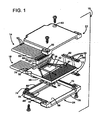
- Connecteur selon l'une quelconque des revendications précédentes, dans lequel le corps (202) est un élément de circuit, comportant une première partie linéaire (222) supportant les parties de douille (254) au niveau de leurs deuxièmes extrémités (262), et une deuxième partie linéaire (220) espacée de la première partie linéaire (222), supportant au moins certaines des parties de douille (254) au niveau de leurs premières extrémités.
- Connecteur selon l'une quelconque des revendications précédentes, dans lequel le corps (202) est un cadre, supportant les extrémités des parties de douille (254) et comportant une ouverture alignée avec la partie intermédiaire des parties de douille (254).
- Connecteur selon l'une quelconque des revendications précédentes, dans lequel le corps (202) englobe des parties de surface métallisées (246) sur lesquelles sont soudées les extrémités des parties de douille (254).
- Connecteur selon la revendication 10, dans lequel les parties de surface métallisées englobent un premier réseau de plots (246, 244), positionnés chacun entre lesdits conducteurs d'entrée adjacents (240).
- Connecteur selon la revendication 11, dans lequel les blindages (234) des conducteurs d'entrée (240) sont connectés à des plots adjacents (246, 244) du premier réseau.
- Connecteur selon la revendication 12, dans lequel les blindages (234) sont connectés les uns aux autres au niveau du premier réseau.
- Connecteur selon l'une quelconque des revendications précédentes, dans lequel les parties de douille (254) comprennent deux sous-ensembles, les éléments de chaque sous-ensemble alternant les uns avec les autres, les premières extrémités des parties de douille (254) des éléments de l'un des sous-ensembles s'étendant au-delà des premières extrémités des éléments de l'autre sous-ensemble.
Applications Claiming Priority (2)
| Application Number | Priority Date | Filing Date | Title |
|---|---|---|---|
| US10/794,643 US7371128B2 (en) | 2003-10-14 | 2004-03-05 | Cable terminal with air-enhanced contact pins |
| PCT/US2005/007042 WO2005096441A1 (fr) | 2004-03-05 | 2005-03-04 | Terminal de cable a chevilles de contact a amelioration pneumatique |
Publications (2)
| Publication Number | Publication Date |
|---|---|
| EP1721365A1 EP1721365A1 (fr) | 2006-11-15 |
| EP1721365B1 true EP1721365B1 (fr) | 2010-12-15 |
Family
ID=34961766
Family Applications (1)
| Application Number | Title | Priority Date | Filing Date |
|---|---|---|---|
| EP05724559A Expired - Fee Related EP1721365B1 (fr) | 2004-03-05 | 2005-03-04 | Terminal de cable a chevilles de contact a amelioration pneumatique |
Country Status (6)
| Country | Link |
|---|---|
| US (1) | US7371128B2 (fr) |
| EP (1) | EP1721365B1 (fr) |
| JP (1) | JP4624405B2 (fr) |
| CN (1) | CN1930737B (fr) |
| DE (1) | DE602005025314D1 (fr) |
| WO (1) | WO2005096441A1 (fr) |
Families Citing this family (19)
| Publication number | Priority date | Publication date | Assignee | Title |
|---|---|---|---|---|
| JP2007048491A (ja) * | 2005-08-08 | 2007-02-22 | D D K Ltd | 電気コネクタ |
| US7476131B2 (en) | 2006-09-29 | 2009-01-13 | Nellcor Puritan Bennett Llc | Device for reducing crosstalk |
| US7470155B1 (en) * | 2007-07-25 | 2008-12-30 | Samtec, Inc. | High-density connector |
| JP5563207B2 (ja) * | 2008-08-01 | 2014-07-30 | スリーエム イノベイティブ プロパティズ カンパニー | 終端コネクタ |
| US7740508B2 (en) * | 2008-09-08 | 2010-06-22 | 3M Innovative Properties Company | Probe block assembly |
| GB201119050D0 (en) | 2011-11-04 | 2011-12-14 | Rolls Royce Plc | Electrical harness connector |
| GB201119045D0 (en) * | 2011-11-04 | 2011-12-14 | Rolls Royce Plc | Electrical harness |
| KR101277773B1 (ko) * | 2012-12-28 | 2013-06-24 | 우진 일렉트로나이트(주) | 홀더 교체부재 및 이를 포함하는 홀더 조립체 |
| CN103247917A (zh) | 2013-04-11 | 2013-08-14 | 富士康(昆山)电脑接插件有限公司 | 同轴线缆组件 |
| GB201308029D0 (en) | 2013-05-03 | 2013-06-12 | Rolls Royce Plc | Electrical harness connector |
| DE102013225794A1 (de) * | 2013-12-12 | 2015-06-18 | Leoni Kabel Holding Gmbh | Kontaktanbindung von geschirmten Datenleitungen an einer Platine sowie Verfahren zur Kontaktierung mehrerer geschirmter Datenleitungen an einer Platine |
| US9810715B2 (en) * | 2014-12-31 | 2017-11-07 | Tektronix, Inc. | High impedance compliant probe tip |
| US10892574B2 (en) * | 2016-10-21 | 2021-01-12 | Paricon Technologies Corporation | Cable-to-board connector |
| US9893446B1 (en) * | 2017-06-26 | 2018-02-13 | Greenconn Corp. | High speed connector and transmission module thereof |
| US9979136B1 (en) * | 2017-06-26 | 2018-05-22 | Greenconn Corporation | High speed connector and transmission module thereof |
| WO2020112474A1 (fr) * | 2018-11-30 | 2020-06-04 | Corning Optical Communications Rf Llc | Contacts électriques compressibles à sections coupées par divaricelle |
| US11092996B2 (en) * | 2019-08-20 | 2021-08-17 | Getac Technology Corporation | Electronic device |
| CN110600944A (zh) * | 2019-09-18 | 2019-12-20 | 环胜电子(深圳)有限公司 | 电连接器结构 |
| WO2023229627A1 (fr) * | 2022-05-25 | 2023-11-30 | Rakuten Symphony Uk Ltd | Interconnexion coaxiale rf à broche de ressort |
Family Cites Families (22)
| Publication number | Priority date | Publication date | Assignee | Title |
|---|---|---|---|---|
| US3548829A (en) * | 1968-10-21 | 1970-12-22 | Frigitronics Of Conn Inc | Cryosurgical instrument |
| US4041380A (en) | 1976-03-12 | 1977-08-09 | Kastar, Inc. | Multi-function tester with removable circuit cartridge |
| US4209742A (en) * | 1976-10-13 | 1980-06-24 | Tektronix, Inc. | Modular probe system |
| DE7914951U1 (fr) | 1979-05-23 | 1989-07-13 | Feinmetall Gmbh, 7033 Herrenberg, De | |
| US4418314A (en) * | 1980-10-20 | 1983-11-29 | The United States Of America As Represented By The Secretary Of The Army | High impedance fast voltage probe |
| JPS58144215U (ja) * | 1982-03-23 | 1983-09-28 | 岩崎通信機株式会社 | 変位計の静電容量プロ−プ |
| GB2125236A (en) | 1982-08-11 | 1984-02-29 | Tektronix Inc | Stress-isolating electrical connections |
| DE3500226A1 (de) | 1985-01-05 | 1986-07-10 | Riba-Prüftechnik GmbH, 7801 Schallstadt | Tastnadel fuer eine leiterplatten-pruefeinrichtung |
| US4739259A (en) | 1986-08-01 | 1988-04-19 | Tektronix, Inc. | Telescoping pin probe |
| DE3815573A1 (de) | 1988-05-06 | 1989-11-16 | Feinmetall Gmbh | Pruefadapter |
| US4904935A (en) * | 1988-11-14 | 1990-02-27 | Eaton Corporation | Electrical circuit board text fixture having movable platens |
| US5084673A (en) * | 1989-06-15 | 1992-01-28 | Nhk Spring Co., Ltd. | Electric contact probe |
| US5046968A (en) * | 1989-09-28 | 1991-09-10 | Tri-Star Incorporated | Electrical connector contact having an electrical component disposed in a central internal cavity |
| US5103165A (en) * | 1990-11-19 | 1992-04-07 | Static Control Components, Inc. | Insulated, hand-held non-contacting voltage detection probe |
| US5196789A (en) * | 1991-01-28 | 1993-03-23 | Golden Joseph R | Coaxial spring contact probe |
| US5248266A (en) * | 1992-09-15 | 1993-09-28 | Itt Coporation | Connector with sealed component contact |
| JPH10239350A (ja) * | 1997-02-25 | 1998-09-11 | Seiko Epson Corp | 計測装置のテストプローブおよびこれを備えたテスター |
| US6407562B1 (en) * | 1999-07-29 | 2002-06-18 | Agilent Technologies, Inc. | Probe tip terminating device providing an easily changeable feed-through termination |
| US6552523B2 (en) * | 2001-05-24 | 2003-04-22 | Tektronix, Inc. | Combination low capacitance probe tip and socket for a measurement probe |
| US6935866B2 (en) * | 2002-04-02 | 2005-08-30 | Adc Telecommunications, Inc. | Card edge coaxial connector |
| US6575772B1 (en) * | 2002-04-09 | 2003-06-10 | The Ludlow Company Lp | Shielded cable terminal with contact pins mounted to printed circuit board |
| US6688906B2 (en) * | 2002-05-28 | 2004-02-10 | Agilent Technologies Inc. | Probes and methods for testing electrical circuits |
-
2004
- 2004-03-05 US US10/794,643 patent/US7371128B2/en not_active Expired - Fee Related
-
2005
- 2005-03-04 JP JP2007502002A patent/JP4624405B2/ja not_active Expired - Fee Related
- 2005-03-04 DE DE602005025314T patent/DE602005025314D1/de active Active
- 2005-03-04 CN CN200580007193.2A patent/CN1930737B/zh not_active Expired - Fee Related
- 2005-03-04 WO PCT/US2005/007042 patent/WO2005096441A1/fr not_active Application Discontinuation
- 2005-03-04 EP EP05724559A patent/EP1721365B1/fr not_active Expired - Fee Related
Also Published As
| Publication number | Publication date |
|---|---|
| EP1721365A1 (fr) | 2006-11-15 |
| WO2005096441A1 (fr) | 2005-10-13 |
| CN1930737B (zh) | 2010-09-29 |
| JP2007527600A (ja) | 2007-09-27 |
| DE602005025314D1 (de) | 2011-01-27 |
| US20050079772A1 (en) | 2005-04-14 |
| US7371128B2 (en) | 2008-05-13 |
| JP4624405B2 (ja) | 2011-02-02 |
| CN1930737A (zh) | 2007-03-14 |
Similar Documents
| Publication | Publication Date | Title |
|---|---|---|
| EP1721365B1 (fr) | Terminal de cable a chevilles de contact a amelioration pneumatique | |
| US6575772B1 (en) | Shielded cable terminal with contact pins mounted to printed circuit board | |
| US7090501B1 (en) | Connector apparatus | |
| US11637403B2 (en) | Electrical connector with high speed mounting interface | |
| US7766662B2 (en) | Surface mount coaxial connector assembly | |
| CN105659441B (zh) | 直接附着的连接器 | |
| US6712620B1 (en) | Coaxial elastomeric connector system | |
| EP1676139B1 (fr) | Terminal de cable a chevilles de contact comprenant un composant electrique | |
| MXPA03000109A (es) | Sistema de interconexion. | |
| CN109565122B (zh) | 直接附连连接器 | |
| US9172195B2 (en) | Coaxial cable end connector | |
| US20020125967A1 (en) | Air dielectric backplane interconnection system | |
| US20030176085A1 (en) | Electrical connector assembly | |
| JP4102751B2 (ja) | 同軸ケーブル用の複数の終端ソケットを受け取るためのソケット・コネクタ | |
| EP0160423A2 (fr) | Connecteur coaxial pour lignes de transmission à impédance contrôlée | |
| JP2007534110A (ja) | 多重ワイヤケーブルアセンブリ用コネクタシェル | |
| JPH11337577A (ja) | プローブ構造 |
Legal Events
| Date | Code | Title | Description |
|---|---|---|---|
| PUAI | Public reference made under article 153(3) epc to a published international application that has entered the european phase |
Free format text: ORIGINAL CODE: 0009012 |
|
| 17P | Request for examination filed |
Effective date: 20060830 |
|
| AK | Designated contracting states |
Kind code of ref document: A1 Designated state(s): DE FR GB |
|
| DAX | Request for extension of the european patent (deleted) | ||
| RBV | Designated contracting states (corrected) |
Designated state(s): DE FR GB |
|
| 17Q | First examination report despatched |
Effective date: 20071109 |
|
| RAP1 | Party data changed (applicant data changed or rights of an application transferred) |
Owner name: PRECISION INTERCONNECT, INC. |
|
| GRAP | Despatch of communication of intention to grant a patent |
Free format text: ORIGINAL CODE: EPIDOSNIGR1 |
|
| GRAS | Grant fee paid |
Free format text: ORIGINAL CODE: EPIDOSNIGR3 |
|
| GRAA | (expected) grant |
Free format text: ORIGINAL CODE: 0009210 |
|
| AK | Designated contracting states |
Kind code of ref document: B1 Designated state(s): DE FR GB |
|
| REG | Reference to a national code |
Ref country code: GB Ref legal event code: FG4D |
|
| REF | Corresponds to: |
Ref document number: 602005025314 Country of ref document: DE Date of ref document: 20110127 Kind code of ref document: P |
|
| PLBE | No opposition filed within time limit |
Free format text: ORIGINAL CODE: 0009261 |
|
| STAA | Information on the status of an ep patent application or granted ep patent |
Free format text: STATUS: NO OPPOSITION FILED WITHIN TIME LIMIT |
|
| 26N | No opposition filed |
Effective date: 20110916 |
|
| REG | Reference to a national code |
Ref country code: DE Ref legal event code: R097 Ref document number: 602005025314 Country of ref document: DE Effective date: 20110916 |
|
| REG | Reference to a national code |
Ref country code: FR Ref legal event code: PLFP Year of fee payment: 12 |
|
| REG | Reference to a national code |
Ref country code: FR Ref legal event code: PLFP Year of fee payment: 13 |
|
| REG | Reference to a national code |
Ref country code: FR Ref legal event code: PLFP Year of fee payment: 14 |
|
| PGFP | Annual fee paid to national office [announced via postgrant information from national office to epo] |
Ref country code: ES Payment date: 20190220 Year of fee payment: 15 Ref country code: DE Payment date: 20190219 Year of fee payment: 15 |
|
| PGFP | Annual fee paid to national office [announced via postgrant information from national office to epo] |
Ref country code: FR Payment date: 20200113 Year of fee payment: 16 |
|
| REG | Reference to a national code |
Ref country code: DE Ref legal event code: R119 Ref document number: 602005025314 Country of ref document: DE |
|
| PG25 | Lapsed in a contracting state [announced via postgrant information from national office to epo] |
Ref country code: DE Free format text: LAPSE BECAUSE OF NON-PAYMENT OF DUE FEES Effective date: 20201001 |
|
| GBPC | Gb: european patent ceased through non-payment of renewal fee |
Effective date: 20200304 |
|
| PG25 | Lapsed in a contracting state [announced via postgrant information from national office to epo] |
Ref country code: GB Free format text: LAPSE BECAUSE OF NON-PAYMENT OF DUE FEES Effective date: 20200304 |
|
| PG25 | Lapsed in a contracting state [announced via postgrant information from national office to epo] |
Ref country code: FR Free format text: LAPSE BECAUSE OF NON-PAYMENT OF DUE FEES Effective date: 20210331 |