EP1720719B1 - Tyre for vehicles, in particular motor vehicles - Google Patents
Tyre for vehicles, in particular motor vehicles Download PDFInfo
- Publication number
- EP1720719B1 EP1720719B1 EP04736876A EP04736876A EP1720719B1 EP 1720719 B1 EP1720719 B1 EP 1720719B1 EP 04736876 A EP04736876 A EP 04736876A EP 04736876 A EP04736876 A EP 04736876A EP 1720719 B1 EP1720719 B1 EP 1720719B1
- Authority
- EP
- European Patent Office
- Prior art keywords
- tyre
- tyre according
- tread
- blocks
- membranes
- Prior art date
- Legal status (The legal status is an assumption and is not a legal conclusion. Google has not performed a legal analysis and makes no representation as to the accuracy of the status listed.)
- Not-in-force
Links
Images


Classifications
-
- B—PERFORMING OPERATIONS; TRANSPORTING
- B60—VEHICLES IN GENERAL
- B60C—VEHICLE TYRES; TYRE INFLATION; TYRE CHANGING; CONNECTING VALVES TO INFLATABLE ELASTIC BODIES IN GENERAL; DEVICES OR ARRANGEMENTS RELATED TO TYRES
- B60C7/00—Non-inflatable or solid tyres
- B60C7/22—Non-inflatable or solid tyres having inlays other than for increasing resiliency, e.g. for armouring
-
- B—PERFORMING OPERATIONS; TRANSPORTING
- B60—VEHICLES IN GENERAL
- B60C—VEHICLE TYRES; TYRE INFLATION; TYRE CHANGING; CONNECTING VALVES TO INFLATABLE ELASTIC BODIES IN GENERAL; DEVICES OR ARRANGEMENTS RELATED TO TYRES
- B60C11/00—Tyre tread bands; Tread patterns; Anti-skid inserts
- B60C11/14—Anti-skid inserts, e.g. vulcanised into the tread band
- B60C11/18—Anti-skid inserts, e.g. vulcanised into the tread band of strip form, e.g. metallic combs, rubber strips of different wear resistance
-
- B—PERFORMING OPERATIONS; TRANSPORTING
- B60—VEHICLES IN GENERAL
- B60C—VEHICLE TYRES; TYRE INFLATION; TYRE CHANGING; CONNECTING VALVES TO INFLATABLE ELASTIC BODIES IN GENERAL; DEVICES OR ARRANGEMENTS RELATED TO TYRES
- B60C7/00—Non-inflatable or solid tyres
- B60C7/24—Non-inflatable or solid tyres characterised by means for securing tyres on rim or wheel body
- B60C7/26—Non-inflatable or solid tyres characterised by means for securing tyres on rim or wheel body using bolts
-
- Y—GENERAL TAGGING OF NEW TECHNOLOGICAL DEVELOPMENTS; GENERAL TAGGING OF CROSS-SECTIONAL TECHNOLOGIES SPANNING OVER SEVERAL SECTIONS OF THE IPC; TECHNICAL SUBJECTS COVERED BY FORMER USPC CROSS-REFERENCE ART COLLECTIONS [XRACs] AND DIGESTS
- Y10—TECHNICAL SUBJECTS COVERED BY FORMER USPC
- Y10T—TECHNICAL SUBJECTS COVERED BY FORMER US CLASSIFICATION
- Y10T152/00—Resilient tires and wheels
- Y10T152/10—Tires, resilient
- Y10T152/10135—Armored
- Y10T152/10171—Casing construction
- Y10T152/1018—Embedded
-
- Y—GENERAL TAGGING OF NEW TECHNOLOGICAL DEVELOPMENTS; GENERAL TAGGING OF CROSS-SECTIONAL TECHNOLOGIES SPANNING OVER SEVERAL SECTIONS OF THE IPC; TECHNICAL SUBJECTS COVERED BY FORMER USPC CROSS-REFERENCE ART COLLECTIONS [XRACs] AND DIGESTS
- Y10—TECHNICAL SUBJECTS COVERED BY FORMER USPC
- Y10T—TECHNICAL SUBJECTS COVERED BY FORMER US CLASSIFICATION
- Y10T152/00—Resilient tires and wheels
- Y10T152/10—Tires, resilient
- Y10T152/10135—Armored
- Y10T152/10234—Interliners
-
- Y—GENERAL TAGGING OF NEW TECHNOLOGICAL DEVELOPMENTS; GENERAL TAGGING OF CROSS-SECTIONAL TECHNOLOGIES SPANNING OVER SEVERAL SECTIONS OF THE IPC; TECHNICAL SUBJECTS COVERED BY FORMER USPC CROSS-REFERENCE ART COLLECTIONS [XRACs] AND DIGESTS
- Y10—TECHNICAL SUBJECTS COVERED BY FORMER USPC
- Y10T—TECHNICAL SUBJECTS COVERED BY FORMER US CLASSIFICATION
- Y10T152/00—Resilient tires and wheels
- Y10T152/10—Tires, resilient
- Y10T152/10495—Pneumatic tire or inner tube
Definitions
- the present invention relates to a tyre for vehicles.
- tyres which have radial half-sect ions in the shape of an omega and comprise a tread and two convex sidewalls, each of which ends in a bead which, in use, can co-operate in a flush manner with an annular portion of a corresponding rim.
- a chamber which, again in use, is filled with air or another pressurised fluid. The pressure of the fluid in the said chamber is determined according to the type of tyre, and to the stress conditions to which it is assumed that the tyre itself may be subjected.
- tyres Although the known tyres are universally used, they suffer from some disadvantages. Firstly, specifically because of their shape and the fact that they are pressurised, they have high levels of rolling resistance caused by high levels of hysteresis, which in use are responsible for heating of the tyre and uncontrollable variation of the efficiency and reliability of the tyre itself.
- the tread is grooved to form a plurality of channels which are transverse relative to the direction of running of the vehicle, and which, since they open up to the exterior of the tyre, discharge the water which is present into the area of interface of the tyre/road surface.
- the presence of these transverse channels makes it possible to increase the road hold in wet conditions, on the other hand it is a source of troublesome noise emissions.
- the type, dimensions and distribution of these transverse channels on the tread are therefore always a compromise between the various requirements.
- the known tyres require periodic checks on the inflation pressure, which varies over a period of time as a result of the inevitable leakages, and the tyres also need to be replaced if they are punctured.
- the known tyres determine the geometry of the rim, which must have a perimetric tubular portion which is free from apertures, in order to delimit the chamber for the pressurised fluid, and must permit fitting of the inflation value.
- the wheel/rim assembly has relatively high weights which generate inevitable forces of inertia, which, as is known, affect both the acceleration and the braking.
- the object of the invention is thus to provide a tyre for vehicles which makes it possible to solve the above-described problems simply and economically, and in particular which makes it possible to obtain a high level of driving comfort in any condition in which it is used.
- a tyre for vehicles, in particular for motor vehicles, which has an axis of symmetry and comprises a tread, two sidewalls, two beads which are attached to a wheel rim made of elastomer material, and at least one tubular reinforcement body which is coaxial to the said axis, is surrounded by the said tread, and extends between the said sidewalls; each of the said sidewalls comprising a respective resilient annular membrane with a straight generatrix which forms an angle other than 90° with the axis of the tyre; characterised in that the said tubular reinforcement body comprises an annular belt and a plurality of blocks which are supported by the said annular belt in positions which are adjacent to one another, and can be forced against one another in order to apply resistance to the circumferential actions of compression which are present on the tyre during rotation of the tyre itself.
- the said tubular body has a dimension, measured parallel to the said axis, which is substantially the same as that of the tread measured in the same direction.
- the said membranes are stretched between the said tread and the said beads, such as to be pre-tensioned in the absence of loads on the tyre.
- the generatrices of the said membranes converge towards one another such as to meet at a point outside the tread.
- the generatrices of the said membranes converge towards one another such as to meet at a point inside the tyre.
- 1 indicates as a whole a wheel unit for a vehicle, and in particular a motor vehicle (not illustrated), comprising a wheel rim 2 ( figures 2 and 3 ), and a tyre 3 fitted onto the wheel rim 2 itself.
- the wheel rim 2 comprises a central attachment portion 5, and two radial annular flanges 6 which project from the portion 5 and support respective seats 7, each of which accommodates a corresponding bead 8 of the tyre 3.
- the beads 8 each have their own anchorage projection 9, and are engaged with the seats 7 by respective annular discs 10 which are connected to the respective flanges 6 by means of screws 11.
- the portion 5 comprises a cylindrical wall 12, which extends coaxially to the axis 13 of the wheel rim 2 in the positions facing the tyre 3, in order to connect the flanges 6 to one another, and is provided with a plurality of permanently open through-apertures 14, only one, of which can be seen in figures 2 and 3 .
- the tyre 3, which can support the load transmitted by the wheel rim 2 without needing to be pressurised by air or other pressurised fluids, comprises two sidewalls 15, which are connected firstly to the beads 8 and secondly to a tread 16.
- the beads 8, the tread 16 and the sidewalls 15 are made of elastomer material, as will become more apparent from the following description.
- the tyre 3 additionally comprises a homogenous tubular reinforcement body 18 ( figures 2 and 3 ), which extends coaxially to the axis 13, and is made of a material other than the said elastomer materials, and preferably of harmonic steel or of fibre-reinforced plastics material of the thermoplastic or thermosetting type.
- the tubular body 18 has a dimension measured parallel to the axis 13 which is substantially the same as that of the tread 16 measured in the same direction, and is delimited radially by two cylindrical lateral surfaces 18a and 18b which are coaxial to the axis 13 and have generatrix lines which are straight, and are parallel to one another and to the axis 13.
- the tubular body 18 is a corrugated body with a plurality of circumferential ribs 19, which delimit between one another a plurality of circumferential grooves 20.
- the tread 16 is vulcanised on the outer surface of the tubular body 18, which is thus at least partially embedded in the elastomer material of the tread 16 itself.
- the tread 16 is provided with a plurality of radial through-apertures 20, each of which communicates with a corresponding through-aperture 21 provided in the tubular body 18.
- the apertures 20 and 21 are elongate in the circumferential direction, and are aligned with one another in order to form circumferential rows of apertures which are spaced from one another in an axial direction.
- the apertures 20 are closed by means of materials 20a which are permeable only to water, and advantageously by means of porous materials.
- the tread 16 is grooved by producing only a plurality of circumferential grooves 22, into which there open the through-apertures 20 provided through the tread 16.
- each of the sidewalls 15 comprises a respective frusto-conical resilient annular membrane 24 with a straight generatrix which forms an angle A other than 90° with the axis 13, and is advantageously variable between 75 and 85°.
- the generatrices of the membranes 24 converge towards one another and towards the tread 16, meeting at a point, not illustrated, outside the tread 16 itself, whereas in figure 2 , the generatrices diverge from the wheel rim 2 and thus meet at a point inside the tyre 3.
- the membranes 24 have cross-sections which are substantially constant in a radial direction, and radial half-sections which are substantially rectangular, and, according to a first embodiment, are reinforced by means of fibre materials not shown in the attached figures, such as to be anisotropic.
- the fibres of the fibre material are distributed and oriented such as to prevent localised deformations of the membranes 24 under static load, in particular in the area immediately beneath the wheel rim 2.
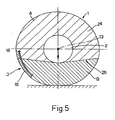
- the fibres are distributed and oriented such that the tension stresses present in the different points of the membranes in conditions in which a load is applied, are contained within a dihedron 26 which is tangent to the beads 8, has a vertex parallel to the axis 13, and is disposed in use below the axis 13 itself, as illustrated in figure 5 .
- the portions A ( figure 5 ) of the membranes 24 which are contained within the dihedron 26 are stretched between the corresponding portions of the tubular body 18 and the wheel rim 2, whereas the portions a of the membranes below the dihedron 26 are not subjected in practice to tension stresses, and can thus be deformed freely under the action of the load transmitted by the wheel rim 2.
- the actual radius of curvature of the part of the tyre beneath the dihedron 26 increases, tending towards infinity at the vertical plane which passes through the axis 13 ( figure 5 ).
- the part of the tyre which is subjected to traction stress, i.e. which is contained within the dihedron 26, supports the load, thus guaranteeing the resilience required for satisfactory driving comfort.
- the wheel rim 2 which, as is known, transmits the load to the tyre, is "suspended" from the portions A of the membranes 24, by this means "releasing" the portions B.
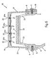
- the variant illustrated in figure 6 relates to a tyre 30 which differ from the tyre 3 only in that the membranes 24 are made of isotropic and homogeneous elastomer material.
- the membranes 24 are made of polybutadiene rubbers or polyisoprene rubbers, treated in order to withstand atmospheric agents, or of polycondensate of dimethylsilanol and derivatives, when the methyl groups are replaced by vinyl or phenolic groups.
- each of the membranes 24 At rest, i.e. in a non-deformed condition, each of the membranes 24 has radial dimensions which are smaller than the radial distance between the tread 16 and the corresponding bead 8.
- each membrane 24 When it is connected to the tread and to the corresponding bead 8, each membrane 24 is stretched radially such that in the condition in which the tyre is at rest, i.e. in the absence of external stresses, it is perfectly pre-tensioned.
- the level of pre-tensioning of the membranes 24 in selected according to the load which acts on the tyre, and in each case such that in use, i.e. when the tyre is in a loaded condition, the portions B of the membranes 24 still have a residual traction load.
- the generatrix of the membranes 24 is always kept straight in practice, including on the vertical plans which passes through the axis of the tyre.
- the wheel rim comprises an annular portion 31 ( figure 6 ) made of elastomer material, which in use is disposed coaxially to the axis of the wheel rim and faces the body 18, such as to constitute under limit conditions a support or a stop for the body 18 itself.
- the portion 31 is supported by a metal portion 32 of the wheel rim, which portion is supported by a plurality of spokes 33.
- Figures 7 and 8 illustrate partially a tubular reinforcement body 35, which is always associated with the tread 16, has a dimension measured parallel to the axis 13 which is substantially the same as that of the tread 16 measured in the same direction, and differs from the reinforcement body 18 in that it has predetermined differentiated resistance to stress, i.e. which is dependent on the stress to which it is subjected.
- the tubular body 35 comprises a continuous outer annular belt 36 and a plurality of blocks 37 which are supported by the belt 36 itself.
- the belt 36 is flexibly and can withstand the circumferential tension actions which act on the reinforcement body 35, and preferably comprises a portion 38 of elastomer material and a plurality of reinforcement threads or fibres 39 which may or may not be braided, embedded in the portion 38 of elastomer material.
- the belt 36 which extends along the entire width of the tread 16, is connected integrally to the tread 16 itself, for example by means of vulcanisation or by being glued, or in a manner such that it can be dismantled or detached, such as to permit replacement of the tread 16 alone when it has reached a limit wear value.
- the belt 36 does not have the portion 38 of elastomer material, and comprises only a braid of threads or strips.
- the belt 36 supports the blockers 37, which are connected integrally to the belt 36, for example by being vulcanised or simply by being glued, project towards the interior of the tyre 3, and can create action which resists the circumferential actions of compression which act on the reinforcement body 35 during rotation of the tyre 3.
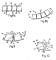
- the blocks 37 which can consist of solid bodies, as illustrated in figures 7 and 8 , or of hollow bodies as illustrated in figures 9 and 10 , are adjacent to one another and aligned in order to define a plurality of axial rows 41 of blocks, i.e. which are parallel to the axis 13 of the tyre, and a plurality of circumferential rows 42 of blocks.
- the blocks 37 have the same dimensions and geometry as one another, and each have a frusto-conical form with a quadrangular base, which is advantageously rectangular with the larger side parallel to the axis 13.
- the blocks 37 are tapered towards the interior of the tyre 3 and each have a respective larger base which faces the belt 36 and is connected to the larger base of the adjacent block 37 by means of a respective flexible joining portion 43 ( figures 8 and 9 ).
- the joining portions 43 define respective virtual hinges 44 which hinge each block 37 on the one adjacent to it.
- the blocks 37 constitute together with the flexible joining portions 43 parts of a flexibly thermoplastic material alveolar body 45 made in a single piece, advantageously from polypropylene or polyamide material.
- the blocks 37 are solid bodies made of plastics or elastomer material, and are connected to one another in order to define a monolithic body. In both cases, the blocks 37 are shaped such that, if the tyre 3 is unloaded, their lateral walls 46 are simply disposed adjacent to one another, or are forced against one another in order to define a preloaded reinforcement body.
- the various portions of the reinforcement body 35 act differently according to the position which they occupy in relation to the area of contact with the support surface of the wheel unit 1. Specifically, in the area of contact of the wheel unit - support surface, as a result of the load transmitted to the tread 16, the blocks 37 are rotated relative to one another in opposite directions around a respective axis of pivoting (as illustrated in figure 8b ), and define between one another respective V-shaped notches 49 which widen towards the interior of the tyre 3, whereas in the areas to the right and left of the said area of contact, they are forced against one another (as illustrated in figure 8b ), in order to withstand the load transmitted to the tyre 3 by the wheel rim 2.
- the virtual hinges 44 apply minimal resistance to the deflection of the reinforcement body towards the interior of the tyre 2, such that the various blocks 37 rotate in opposite directions to one another, thus becoming spaced from one another progressively and in proportion with their distance from the step 50, as illustrated in figure 7 .
- the blocks 37 which are disposed in the vicinity of the step 50 delimit between one another a series of V-shaped notches 49, the widening of which, again as can be seen from figure 7 , is variable, and reaches a maximum value at the step 50, and values which gradually decrease as the distance from the step 50 itself increase.
- each portion 52 comprises a solid bead 52a, from which there extend integrally the resilient lateral walls 46 of the respective blocks 37.
- the virtual hinge 44 which is disposed in the solution in figure 9 between two adjacent blocks 37, is replaced by two virtual hinges 53 and 54, which are each defined by a sections of the wall of the corresponding block 37 adjacent to the bead 53.
- the hinges 53 and 54 are thus displaced towards the free ends of the blocks 37, such that in addition to a predetermined angle of rotation of the blocks 37, the solid beads 52a apply torque which opposes that which rotates the blocks 37 opening up, thus limiting the deformation of the reinforcement body 35 and of the tread 16 towards the interior of the tyre 3.
- the tyres 3,30 described ensure optimum resilience and deformability when loaded, and simultaneously a reduced hysteresis.
- These particular features are derived partly from the presence of the membranes 24, and partly from the design characteristics of the reinforcement bodies 18 and 35.
- body 35 is provided, it is obvious in particular that the belt 36 and the blocks 37 allows the tyre to adapt to the different load conditions and according to the obstacles encountered during rolling, thus becoming deformed differently and in a controlled manner according to the stress to which it is subjected.
- the tyre consequently obtains fluidity of performance even in conditions in which there are substantival obstacles, and therefore a high level of driving comfort in any situation, for the same road hold conditions.
- the passages provided through the tread and the tubular reinforcement body 18 serve a dual purpose. Firstly, in fact, they permit discharge of the water alone which is present in the tread/road surface interface, towards the interior of the tyre, and from there to the exterior, via the apertures 14 in the wheel rim 2.
- the presence of the passages 20 and 21 through the tread 16 and theinsertion body 18 thus provides greater freedom in the grooving of the tread 16 itself, since it avoids creation of the conventional transverse channels for lateral discharge of the water, which are essential in the known solutions in order to obtain the required hold on the road surface, but are a source of undesirable acoustic emissions.
- the presence of the passages 20 and 21 makes it possible to reduce and control the temperature of use of the tyre, with an obvious increase in the efficiency and reliability of the tyre itself.
- the fact of providing porous materials for closure of the apertures 20 prevents intake into the tyre of solid bodies such as stones, gravel and/or sand.
- the greater freedom of form of the wheel rim comprises a substantial reduction in the weight of the wheel unit, as well as a further reduction in the hysteresis of the wheel unit itself.
- both the tubular body 35 and the tread 16 could dispense with the respective apertures 20 and 21, and the wheel rim could dispense with the apertures 14, and could comprise other through-apertures, provided for example through the flanges 6.
- the apertures 20 and 21 could have dimensions and/or geometries which are also very different from those illustrated by way of example, and in particular they could have axial dimensions which are particularly small, in order to prevent the intake of foreign bodies into the tyre.
- the membranes 24 could constitute only an intermediate or end part of the respective sidewalls 15, or they could have cross-sections which are variable in a radial direction. If the membranes are pre-tensioned, when "at rest” they have a radial dimension smaller than the distance between the beads and the tread.
- the blocks 37 could have forms and dimensions other than those described by way of example, and the distribution and orientation of the blocks 37 could also be different.
- a plurality of continuous axial blocks could be provided which are or are not parallel to the axis 13, extending along the entire width of the tread and delimiting between one another respective continuous axial notches.
- the blocks 37 could have heights which differ from one area to another, and in particular could have a reduced height in the vicinity of the said shoulders.
Landscapes
- Engineering & Computer Science (AREA)
- Mechanical Engineering (AREA)
- Tires In General (AREA)
- Arrangement Or Mounting Of Propulsion Units For Vehicles (AREA)
- Polyurethanes Or Polyureas (AREA)
- Transition And Organic Metals Composition Catalysts For Addition Polymerization (AREA)
- Connection Of Motors, Electrical Generators, Mechanical Devices, And The Like (AREA)
Priority Applications (1)
| Application Number | Priority Date | Filing Date | Title |
|---|---|---|---|
| EP09150804A EP2062749B1 (en) | 2004-02-27 | 2004-06-15 | Tyre for vehicles, in particular motor vehicles |
Applications Claiming Priority (2)
| Application Number | Priority Date | Filing Date | Title |
|---|---|---|---|
| IT000120A ITTO20040120A1 (it) | 2004-02-27 | 2004-02-27 | Pneumatico per veicoli, in particolare, autoveicoli |
| PCT/IT2004/000347 WO2005082643A1 (en) | 2004-02-27 | 2004-06-15 | Tyre for vehicles, in particular motor vehicles |
Related Child Applications (1)
| Application Number | Title | Priority Date | Filing Date |
|---|---|---|---|
| EP09150804A Division EP2062749B1 (en) | 2004-02-27 | 2004-06-15 | Tyre for vehicles, in particular motor vehicles |
Publications (2)
| Publication Number | Publication Date |
|---|---|
| EP1720719A1 EP1720719A1 (en) | 2006-11-15 |
| EP1720719B1 true EP1720719B1 (en) | 2009-05-06 |
Family
ID=34897824
Family Applications (2)
| Application Number | Title | Priority Date | Filing Date |
|---|---|---|---|
| EP09150804A Not-in-force EP2062749B1 (en) | 2004-02-27 | 2004-06-15 | Tyre for vehicles, in particular motor vehicles |
| EP04736876A Not-in-force EP1720719B1 (en) | 2004-02-27 | 2004-06-15 | Tyre for vehicles, in particular motor vehicles |
Family Applications Before (1)
| Application Number | Title | Priority Date | Filing Date |
|---|---|---|---|
| EP09150804A Not-in-force EP2062749B1 (en) | 2004-02-27 | 2004-06-15 | Tyre for vehicles, in particular motor vehicles |
Country Status (11)
| Country | Link |
|---|---|
| US (3) | US7950429B2 (it) |
| EP (2) | EP2062749B1 (it) |
| JP (2) | JP4553935B2 (it) |
| CN (2) | CN101654043B (it) |
| AT (2) | ATE495030T1 (it) |
| BR (1) | BRPI0418594A (it) |
| DE (2) | DE602004021036D1 (it) |
| ES (2) | ES2324039T3 (it) |
| IT (1) | ITTO20040120A1 (it) |
| RU (2) | RU2471638C2 (it) |
| WO (1) | WO2005082643A1 (it) |
Families Citing this family (23)
| Publication number | Priority date | Publication date | Assignee | Title |
|---|---|---|---|---|
| JP5066844B2 (ja) * | 2006-06-19 | 2012-11-07 | 横浜ゴム株式会社 | 非空気入りタイヤ |
| US8196625B1 (en) * | 2006-08-08 | 2012-06-12 | Brant Chenoweth | Supplemental tread tire bead lock |
| JP3952211B1 (ja) * | 2006-08-11 | 2007-08-01 | 横浜ゴム株式会社 | 非空気入りタイヤ |
| US8863798B2 (en) * | 2008-10-31 | 2014-10-21 | Fiat Group Automobiles S.P.A. | Airless vehicle tyre, in particular for road vehicles |
| JP4803318B1 (ja) * | 2010-12-02 | 2011-10-26 | 横浜ゴム株式会社 | 空気入りタイヤ |
| CN103287212A (zh) * | 2012-03-05 | 2013-09-11 | 蔡志忠 | 实心胎车轮 |
| CN102673317A (zh) * | 2012-05-30 | 2012-09-19 | 史中河 | 新型不用打汽轮胎 |
| EP2925536B1 (en) | 2013-03-06 | 2018-09-26 | Gatekeeper Systems, Inc. | Wheels for non-motorized vehicles |
| WO2014201368A1 (en) | 2013-06-15 | 2014-12-18 | Ronald Thompson | Annular ring and non-pneumatic tire |
| EP3237229B1 (en) * | 2014-12-22 | 2020-11-18 | Bridgestone Americas Tire Operations, LLC | Tire and wheel assembly having angled interfaces |
| WO2016120872A1 (en) * | 2015-01-29 | 2016-08-04 | Alliance Tire Co. Ltd | A laterally stable pneumatic tire |
| CA2976055A1 (en) | 2015-02-04 | 2016-08-11 | Advancing Mobility, Llc. | Non-pneumatic tire and other annular devices |
| JP6645105B2 (ja) * | 2015-10-06 | 2020-02-12 | 住友ゴム工業株式会社 | 非空気式タイヤ |
| JP6558201B2 (ja) * | 2015-10-19 | 2019-08-14 | 住友ゴム工業株式会社 | エアレスタイヤ |
| US9834040B2 (en) * | 2015-12-10 | 2017-12-05 | The Goodyear Tire & Rubber Company | Structurally supported tire |
| US10639934B2 (en) * | 2016-11-22 | 2020-05-05 | The Goodyear Tire & Rubber Company | Shear band for a structurally supported tire |
| WO2019180750A1 (en) * | 2018-03-23 | 2019-09-26 | Trelleborg Wheel Systems Italia S.P.A. | Solid tyre provided with cushioning holes |
| JP2020006804A (ja) * | 2018-07-09 | 2020-01-16 | 本田技研工業株式会社 | 車両用ホイール |
| CA3106917A1 (en) | 2020-01-24 | 2021-07-24 | Gatekeeper Systems, Inc. | Self-adjusting caster assemblies |
| GB2587247B (en) * | 2020-01-24 | 2021-10-06 | Tree Ass Ltd | Tyre |
| CN112223958B (zh) * | 2020-10-26 | 2022-07-29 | 吉林工程技术师范学院 | 一种仿生机构防爆自行车轮胎及其制备方法 |
| CN114604041A (zh) * | 2020-12-09 | 2022-06-10 | 北京橡胶工业研究设计院有限公司 | 一种防止轮胎脱圈的胎圈锁止环 |
| KR102485920B1 (ko) * | 2021-01-06 | 2023-01-10 | 한국기계연구원 | 복합 구조로 형성된 장애물 극복용 바퀴유닛 |
Family Cites Families (27)
| Publication number | Priority date | Publication date | Assignee | Title |
|---|---|---|---|---|
| JPS521522B1 (it) * | 1971-06-12 | 1977-01-14 | ||
| DE2348038A1 (de) * | 1973-09-24 | 1975-04-03 | Continental Gummi Werke Ag | Fahrzeugluftreifen |
| US4170254A (en) * | 1974-08-23 | 1979-10-09 | Dunlop Limited | Tire with a straight sidewall |
| GB1514474A (en) * | 1974-08-23 | 1978-06-14 | Dunlop Ltd | Tyre and wheel assemblies |
| JPS51151901A (en) * | 1975-06-20 | 1976-12-27 | Bridgestone Corp | Pneumatic safty tire |
| PL112739B1 (en) * | 1976-05-04 | 1980-10-31 | Polyair Maschinenbau Gmbh | Cellular tyre |
| JPS53503A (en) * | 1976-06-25 | 1978-01-06 | Bridgestone Corp | Puncture-proof pueumatic tyre |
| JPS531135A (en) * | 1976-06-25 | 1978-01-07 | Nissan Motor | Partial plating method of plastics |
| GB2003097B (en) * | 1977-08-25 | 1982-11-17 | Dunlop Ltd | Tyres |
| JPS5914364B2 (ja) * | 1980-04-07 | 1984-04-04 | 住友ゴム工業株式会社 | スノ−タイヤ用スパイク |
| JPS58183303A (ja) * | 1982-04-22 | 1983-10-26 | Gengo Kondou | 複数の機能を持つタイヤ |
| WO1984000329A1 (fr) * | 1982-07-16 | 1984-02-02 | Julien Benisti | Systeme antiglissant pour une bande d'entrainement deformable et son application aux pneumatiques, bandes transporteuses ou analogues |
| US4456048A (en) * | 1983-01-24 | 1984-06-26 | Grumman Aerospace Corporation | Dual-modulus band banded tire |
| JPS59199301A (ja) * | 1983-04-26 | 1984-11-12 | ル−ロン・アラベ・ウイリアムス | 乗物用の自己冷却性、空気なし、衝撃吸収性車輪及びそのタイヤ |
| AT386571B (de) * | 1985-12-11 | 1988-09-12 | Semperit Ag | Fahrzeugluftreifen |
| DE3604023A1 (de) * | 1986-02-08 | 1987-08-13 | Continental Gummi Werke Ag | Verfahren und vorrichtung zur messung des rundlaufs bei einem fahrzeugluftreifen |
| US5050656A (en) * | 1990-04-23 | 1991-09-24 | The B. F. Goodrich Company | Non-pneumatic tire wheel |
| JPH0532006U (ja) * | 1991-10-14 | 1993-04-27 | 基雄 根井 | 自動車タイヤに取付けるベルトプーリー |
| DE4207613A1 (de) * | 1992-03-10 | 1993-09-16 | Hans Scheibenpflug | Spikesreifen |
| JPH0899508A (ja) * | 1994-09-30 | 1996-04-16 | Bridgestone Corp | 空気入りタイヤ |
| US6923233B1 (en) * | 1999-09-30 | 2005-08-02 | The Goodyear Tire & Rubber Company | Runflat tire with sawtooth shaped insert |
| CA2393684C (en) * | 1999-12-10 | 2005-08-02 | Michelin Recherche Et Technique S.A. | Structurally supported resilient tire |
| ATE290565T1 (de) * | 2000-02-24 | 2005-03-15 | Michelin Soc Tech | Vulkanisierbare kautschukmischung zur herstellung eines luftreifens und luftreifen, der eine solche zusammensetzung enthält |
| JP4490561B2 (ja) * | 2000-07-14 | 2010-06-30 | 住友ゴム工業株式会社 | 空気入りタイヤ |
| JP4614622B2 (ja) * | 2001-04-16 | 2011-01-19 | ミシュラン ルシェルシュ エ テクニーク ソシエテ アノニム | バイアスプライカーカスを有する構造的に支持された弾性タイヤ |
| KR100810935B1 (ko) * | 2001-08-24 | 2008-03-10 | 소시에떼 드 테크놀로지 미쉐린 | 무공압 타이어 |
| FR2839015A1 (fr) * | 2002-04-29 | 2003-10-31 | Conception & Dev Michelin Sa | Bandage flexible non pneumatique |
-
2004
- 2004-02-27 IT IT000120A patent/ITTO20040120A1/it unknown
- 2004-06-15 AT AT09150804T patent/ATE495030T1/de not_active IP Right Cessation
- 2004-06-15 EP EP09150804A patent/EP2062749B1/en not_active Not-in-force
- 2004-06-15 CN CN2009101421153A patent/CN101654043B/zh not_active Expired - Fee Related
- 2004-06-15 DE DE602004021036T patent/DE602004021036D1/de active Active
- 2004-06-15 AT AT04736876T patent/ATE430661T1/de not_active IP Right Cessation
- 2004-06-15 RU RU2008132423/11A patent/RU2471638C2/ru not_active IP Right Cessation
- 2004-06-15 RU RU2006132456/11A patent/RU2344944C2/ru not_active IP Right Cessation
- 2004-06-15 EP EP04736876A patent/EP1720719B1/en not_active Not-in-force
- 2004-06-15 ES ES04736876T patent/ES2324039T3/es active Active
- 2004-06-15 WO PCT/IT2004/000347 patent/WO2005082643A1/en active Application Filing
- 2004-06-15 ES ES09150804T patent/ES2359040T3/es active Active
- 2004-06-15 DE DE602004031060T patent/DE602004031060D1/de active Active
- 2004-06-15 BR BRPI0418594-3A patent/BRPI0418594A/pt not_active IP Right Cessation
- 2004-06-15 US US10/591,017 patent/US7950429B2/en not_active Expired - Fee Related
- 2004-06-15 JP JP2007500355A patent/JP4553935B2/ja not_active Expired - Fee Related
- 2004-06-15 CN CNB2004800421772A patent/CN100554006C/zh not_active Expired - Fee Related
- 2004-06-15 US US10/590,988 patent/US20080257463A1/en not_active Abandoned
-
2009
- 2009-05-20 JP JP2009121524A patent/JP4860721B2/ja not_active Expired - Fee Related
-
2011
- 2011-04-22 US US13/092,768 patent/US8720505B2/en active Active
Also Published As
| Publication number | Publication date |
|---|---|
| EP2062749A1 (en) | 2009-05-27 |
| EP2062749B1 (en) | 2011-01-12 |
| DE602004021036D1 (de) | 2009-06-18 |
| ATE495030T1 (de) | 2011-01-15 |
| EP1720719A1 (en) | 2006-11-15 |
| ATE430661T1 (de) | 2009-05-15 |
| JP2009179320A (ja) | 2009-08-13 |
| BRPI0418594A (pt) | 2008-01-29 |
| CN101654043B (zh) | 2012-09-05 |
| CN100554006C (zh) | 2009-10-28 |
| RU2344944C2 (ru) | 2009-01-27 |
| ES2359040T3 (es) | 2011-05-17 |
| JP2007525361A (ja) | 2007-09-06 |
| CN101654043A (zh) | 2010-02-24 |
| US20070261774A1 (en) | 2007-11-15 |
| US20080257463A1 (en) | 2008-10-23 |
| US20110192515A1 (en) | 2011-08-11 |
| JP4553935B2 (ja) | 2010-09-29 |
| DE602004031060D1 (de) | 2011-02-24 |
| WO2005082643A1 (en) | 2005-09-09 |
| ES2324039T3 (es) | 2009-07-29 |
| RU2006132456A (ru) | 2008-04-10 |
| CN1922039A (zh) | 2007-02-28 |
| JP4860721B2 (ja) | 2012-01-25 |
| US8720505B2 (en) | 2014-05-13 |
| US7950429B2 (en) | 2011-05-31 |
| ITTO20040120A1 (it) | 2004-05-27 |
| RU2008132423A (ru) | 2010-02-20 |
| RU2471638C2 (ru) | 2013-01-10 |
Similar Documents
| Publication | Publication Date | Title |
|---|---|---|
| US8720505B2 (en) | Tyre for vehicles, in particular motor vehicles | |
| US8991455B2 (en) | Molded article and venting assembly for a rotating mold | |
| US10112442B2 (en) | Non-pneumatic tire | |
| US11090974B2 (en) | Shear deforming non-pneumatic tire spokes | |
| US9975386B2 (en) | Tire/wheel assembly and tread ring | |
| US20060144488A1 (en) | Airless tire | |
| US20180001705A1 (en) | Molded article and improved venting assembly for a rotating mold | |
| WO2014093135A1 (en) | System and method for molding non-pneumatic tires | |
| EP3558696B1 (en) | Method of mounting a non-pneumatic tire onto a hub | |
| KR20110117708A (ko) | 타이어 | |
| CN106457888A (zh) | 具有部分适应性轮毂的非充气式轮胎 | |
| KR20050102665A (ko) | 타이어/휠 조립체 및 런 플랫용 지지체 | |
| EP3507108B1 (en) | Tire with means for setting out studs at the tire surface, and method | |
| WO1999054121A1 (en) | Multi-shot process of producing a non-pneumatic tire |
Legal Events
| Date | Code | Title | Description |
|---|---|---|---|
| PUAI | Public reference made under article 153(3) epc to a published international application that has entered the european phase |
Free format text: ORIGINAL CODE: 0009012 |
|
| 17P | Request for examination filed |
Effective date: 20060927 |
|
| AK | Designated contracting states |
Kind code of ref document: A1 Designated state(s): AT BE BG CH CY CZ DE DK EE ES FI FR GB GR HU IE IT LI LU MC NL PL PT RO SE SI SK TR |
|
| DAX | Request for extension of the european patent (deleted) | ||
| 17Q | First examination report despatched |
Effective date: 20071213 |
|
| GRAP | Despatch of communication of intention to grant a patent |
Free format text: ORIGINAL CODE: EPIDOSNIGR1 |
|
| GRAS | Grant fee paid |
Free format text: ORIGINAL CODE: EPIDOSNIGR3 |
|
| GRAA | (expected) grant |
Free format text: ORIGINAL CODE: 0009210 |
|
| AK | Designated contracting states |
Kind code of ref document: B1 Designated state(s): AT BE BG CH CY CZ DE DK EE ES FI FR GB GR HU IE IT LI LU MC NL PL PT RO SE SI SK TR |
|
| REG | Reference to a national code |
Ref country code: GB Ref legal event code: FG4D |
|
| REG | Reference to a national code |
Ref country code: CH Ref legal event code: EP |
|
| REG | Reference to a national code |
Ref country code: IE Ref legal event code: FG4D |
|
| REF | Corresponds to: |
Ref document number: 602004021036 Country of ref document: DE Date of ref document: 20090618 Kind code of ref document: P |
|
| REG | Reference to a national code |
Ref country code: ES Ref legal event code: FG2A Ref document number: 2324039 Country of ref document: ES Kind code of ref document: T3 |
|
| PG25 | Lapsed in a contracting state [announced via postgrant information from national office to epo] |
Ref country code: AT Free format text: LAPSE BECAUSE OF FAILURE TO SUBMIT A TRANSLATION OF THE DESCRIPTION OR TO PAY THE FEE WITHIN THE PRESCRIBED TIME-LIMIT Effective date: 20090506 Ref country code: FI Free format text: LAPSE BECAUSE OF FAILURE TO SUBMIT A TRANSLATION OF THE DESCRIPTION OR TO PAY THE FEE WITHIN THE PRESCRIBED TIME-LIMIT Effective date: 20090506 Ref country code: PT Free format text: LAPSE BECAUSE OF FAILURE TO SUBMIT A TRANSLATION OF THE DESCRIPTION OR TO PAY THE FEE WITHIN THE PRESCRIBED TIME-LIMIT Effective date: 20090906 |
|
| NLV1 | Nl: lapsed or annulled due to failure to fulfill the requirements of art. 29p and 29m of the patents act | ||
| PG25 | Lapsed in a contracting state [announced via postgrant information from national office to epo] |
Ref country code: SE Free format text: LAPSE BECAUSE OF FAILURE TO SUBMIT A TRANSLATION OF THE DESCRIPTION OR TO PAY THE FEE WITHIN THE PRESCRIBED TIME-LIMIT Effective date: 20090806 Ref country code: NL Free format text: LAPSE BECAUSE OF FAILURE TO SUBMIT A TRANSLATION OF THE DESCRIPTION OR TO PAY THE FEE WITHIN THE PRESCRIBED TIME-LIMIT Effective date: 20090506 Ref country code: PL Free format text: LAPSE BECAUSE OF FAILURE TO SUBMIT A TRANSLATION OF THE DESCRIPTION OR TO PAY THE FEE WITHIN THE PRESCRIBED TIME-LIMIT Effective date: 20090506 Ref country code: SI Free format text: LAPSE BECAUSE OF FAILURE TO SUBMIT A TRANSLATION OF THE DESCRIPTION OR TO PAY THE FEE WITHIN THE PRESCRIBED TIME-LIMIT Effective date: 20090506 |
|
| PG25 | Lapsed in a contracting state [announced via postgrant information from national office to epo] |
Ref country code: EE Free format text: LAPSE BECAUSE OF FAILURE TO SUBMIT A TRANSLATION OF THE DESCRIPTION OR TO PAY THE FEE WITHIN THE PRESCRIBED TIME-LIMIT Effective date: 20090506 Ref country code: DK Free format text: LAPSE BECAUSE OF FAILURE TO SUBMIT A TRANSLATION OF THE DESCRIPTION OR TO PAY THE FEE WITHIN THE PRESCRIBED TIME-LIMIT Effective date: 20090506 Ref country code: CZ Free format text: LAPSE BECAUSE OF FAILURE TO SUBMIT A TRANSLATION OF THE DESCRIPTION OR TO PAY THE FEE WITHIN THE PRESCRIBED TIME-LIMIT Effective date: 20090506 Ref country code: RO Free format text: LAPSE BECAUSE OF FAILURE TO SUBMIT A TRANSLATION OF THE DESCRIPTION OR TO PAY THE FEE WITHIN THE PRESCRIBED TIME-LIMIT Effective date: 20090506 Ref country code: MC Free format text: LAPSE BECAUSE OF NON-PAYMENT OF DUE FEES Effective date: 20090630 |
|
| REG | Reference to a national code |
Ref country code: CH Ref legal event code: PL |
|
| PG25 | Lapsed in a contracting state [announced via postgrant information from national office to epo] |
Ref country code: BE Free format text: LAPSE BECAUSE OF FAILURE TO SUBMIT A TRANSLATION OF THE DESCRIPTION OR TO PAY THE FEE WITHIN THE PRESCRIBED TIME-LIMIT Effective date: 20090506 Ref country code: SK Free format text: LAPSE BECAUSE OF FAILURE TO SUBMIT A TRANSLATION OF THE DESCRIPTION OR TO PAY THE FEE WITHIN THE PRESCRIBED TIME-LIMIT Effective date: 20090506 |
|
| PLBE | No opposition filed within time limit |
Free format text: ORIGINAL CODE: 0009261 |
|
| STAA | Information on the status of an ep patent application or granted ep patent |
Free format text: STATUS: NO OPPOSITION FILED WITHIN TIME LIMIT |
|
| PG25 | Lapsed in a contracting state [announced via postgrant information from national office to epo] |
Ref country code: BG Free format text: LAPSE BECAUSE OF FAILURE TO SUBMIT A TRANSLATION OF THE DESCRIPTION OR TO PAY THE FEE WITHIN THE PRESCRIBED TIME-LIMIT Effective date: 20090806 |
|
| REG | Reference to a national code |
Ref country code: IE Ref legal event code: MM4A |
|
| 26N | No opposition filed |
Effective date: 20100209 |
|
| PG25 | Lapsed in a contracting state [announced via postgrant information from national office to epo] |
Ref country code: CH Free format text: LAPSE BECAUSE OF NON-PAYMENT OF DUE FEES Effective date: 20090630 Ref country code: IE Free format text: LAPSE BECAUSE OF NON-PAYMENT OF DUE FEES Effective date: 20090615 Ref country code: LI Free format text: LAPSE BECAUSE OF NON-PAYMENT OF DUE FEES Effective date: 20090630 |
|
| PG25 | Lapsed in a contracting state [announced via postgrant information from national office to epo] |
Ref country code: GR Free format text: LAPSE BECAUSE OF FAILURE TO SUBMIT A TRANSLATION OF THE DESCRIPTION OR TO PAY THE FEE WITHIN THE PRESCRIBED TIME-LIMIT Effective date: 20090807 |
|
| PG25 | Lapsed in a contracting state [announced via postgrant information from national office to epo] |
Ref country code: IT Free format text: LAPSE BECAUSE OF NON-PAYMENT OF DUE FEES Effective date: 20090615 |
|
| PG25 | Lapsed in a contracting state [announced via postgrant information from national office to epo] |
Ref country code: LU Free format text: LAPSE BECAUSE OF NON-PAYMENT OF DUE FEES Effective date: 20090615 |
|
| PG25 | Lapsed in a contracting state [announced via postgrant information from national office to epo] |
Ref country code: HU Free format text: LAPSE BECAUSE OF FAILURE TO SUBMIT A TRANSLATION OF THE DESCRIPTION OR TO PAY THE FEE WITHIN THE PRESCRIBED TIME-LIMIT Effective date: 20091107 |
|
| PGRI | Patent reinstated in contracting state [announced from national office to epo] |
Ref country code: IT Effective date: 20110616 |
|
| PG25 | Lapsed in a contracting state [announced via postgrant information from national office to epo] |
Ref country code: TR Free format text: LAPSE BECAUSE OF FAILURE TO SUBMIT A TRANSLATION OF THE DESCRIPTION OR TO PAY THE FEE WITHIN THE PRESCRIBED TIME-LIMIT Effective date: 20090506 |
|
| PGFP | Annual fee paid to national office [announced via postgrant information from national office to epo] |
Ref country code: GB Payment date: 20110615 Year of fee payment: 8 |
|
| PG25 | Lapsed in a contracting state [announced via postgrant information from national office to epo] |
Ref country code: CY Free format text: LAPSE BECAUSE OF FAILURE TO SUBMIT A TRANSLATION OF THE DESCRIPTION OR TO PAY THE FEE WITHIN THE PRESCRIBED TIME-LIMIT Effective date: 20090506 |
|
| PGFP | Annual fee paid to national office [announced via postgrant information from national office to epo] |
Ref country code: ES Payment date: 20110715 Year of fee payment: 8 |
|
| GBPC | Gb: european patent ceased through non-payment of renewal fee |
Effective date: 20120615 |
|
| PG25 | Lapsed in a contracting state [announced via postgrant information from national office to epo] |
Ref country code: GB Free format text: LAPSE BECAUSE OF NON-PAYMENT OF DUE FEES Effective date: 20120615 |
|
| REG | Reference to a national code |
Ref country code: ES Ref legal event code: FD2A Effective date: 20131018 |
|
| PG25 | Lapsed in a contracting state [announced via postgrant information from national office to epo] |
Ref country code: ES Free format text: LAPSE BECAUSE OF NON-PAYMENT OF DUE FEES Effective date: 20120616 |
|
| PGFP | Annual fee paid to national office [announced via postgrant information from national office to epo] |
Ref country code: IT Payment date: 20140617 Year of fee payment: 11 Ref country code: DE Payment date: 20140611 Year of fee payment: 11 |
|
| PGFP | Annual fee paid to national office [announced via postgrant information from national office to epo] |
Ref country code: FR Payment date: 20140609 Year of fee payment: 11 |
|
| REG | Reference to a national code |
Ref country code: DE Ref legal event code: R119 Ref document number: 602004021036 Country of ref document: DE |
|
| PG25 | Lapsed in a contracting state [announced via postgrant information from national office to epo] |
Ref country code: IT Free format text: LAPSE BECAUSE OF NON-PAYMENT OF DUE FEES Effective date: 20150615 |
|
| REG | Reference to a national code |
Ref country code: FR Ref legal event code: ST Effective date: 20160229 |
|
| PG25 | Lapsed in a contracting state [announced via postgrant information from national office to epo] |
Ref country code: DE Free format text: LAPSE BECAUSE OF NON-PAYMENT OF DUE FEES Effective date: 20160101 |
|
| PG25 | Lapsed in a contracting state [announced via postgrant information from national office to epo] |
Ref country code: FR Free format text: LAPSE BECAUSE OF NON-PAYMENT OF DUE FEES Effective date: 20150630 |