EP1720039B1 - Darstellung eines zweidimensionalen fächerförmigen Ultraschallfeldes - Google Patents
Darstellung eines zweidimensionalen fächerförmigen Ultraschallfeldes Download PDFInfo
- Publication number
- EP1720039B1 EP1720039B1 EP06252210.7A EP06252210A EP1720039B1 EP 1720039 B1 EP1720039 B1 EP 1720039B1 EP 06252210 A EP06252210 A EP 06252210A EP 1720039 B1 EP1720039 B1 EP 1720039B1
- Authority
- EP
- European Patent Office
- Prior art keywords
- catheter
- image
- ultrasonic
- dimensional
- images
- Prior art date
- Legal status (The legal status is an assumption and is not a legal conclusion. Google has not performed a legal analysis and makes no representation as to the accuracy of the status listed.)
- Active
Links
- 238000002604 ultrasonography Methods 0.000 title claims description 78
- 238000000034 method Methods 0.000 claims description 55
- 238000003384 imaging method Methods 0.000 claims description 39
- 230000008569 process Effects 0.000 claims description 6
- 239000007787 solid Substances 0.000 claims description 6
- 210000003484 anatomy Anatomy 0.000 claims description 4
- 238000002592 echocardiography Methods 0.000 claims description 4
- 238000002059 diagnostic imaging Methods 0.000 claims description 3
- 238000012937 correction Methods 0.000 claims 1
- 238000012217 deletion Methods 0.000 claims 1
- 230000037430 deletion Effects 0.000 claims 1
- 238000012986 modification Methods 0.000 claims 1
- 230000004048 modification Effects 0.000 claims 1
- 210000002216 heart Anatomy 0.000 description 31
- 238000005259 measurement Methods 0.000 description 20
- 210000000056 organ Anatomy 0.000 description 15
- 239000000523 sample Substances 0.000 description 15
- 238000013507 mapping Methods 0.000 description 13
- 210000001519 tissue Anatomy 0.000 description 13
- 230000000747 cardiac effect Effects 0.000 description 12
- 230000000694 effects Effects 0.000 description 9
- 230000006870 function Effects 0.000 description 8
- 230000002452 interceptive effect Effects 0.000 description 7
- 238000002679 ablation Methods 0.000 description 6
- 230000001360 synchronised effect Effects 0.000 description 5
- 230000008859 change Effects 0.000 description 4
- 230000035515 penetration Effects 0.000 description 4
- 238000001356 surgical procedure Methods 0.000 description 4
- 230000001225 therapeutic effect Effects 0.000 description 4
- 238000003491 array Methods 0.000 description 3
- 210000004204 blood vessel Anatomy 0.000 description 3
- 210000005242 cardiac chamber Anatomy 0.000 description 3
- 230000005672 electromagnetic field Effects 0.000 description 3
- 210000001174 endocardium Anatomy 0.000 description 3
- 238000010191 image analysis Methods 0.000 description 3
- 230000007246 mechanism Effects 0.000 description 3
- 238000012545 processing Methods 0.000 description 3
- 210000005241 right ventricle Anatomy 0.000 description 3
- 238000012285 ultrasound imaging Methods 0.000 description 3
- 238000004458 analytical method Methods 0.000 description 2
- 230000017531 blood circulation Effects 0.000 description 2
- 210000002837 heart atrium Anatomy 0.000 description 2
- 238000003672 processing method Methods 0.000 description 2
- 238000012552 review Methods 0.000 description 2
- 210000005245 right atrium Anatomy 0.000 description 2
- 230000011218 segmentation Effects 0.000 description 2
- 238000003325 tomography Methods 0.000 description 2
- 230000005355 Hall effect Effects 0.000 description 1
- 208000035478 Interatrial communication Diseases 0.000 description 1
- 230000004913 activation Effects 0.000 description 1
- 210000000709 aorta Anatomy 0.000 description 1
- 210000001765 aortic valve Anatomy 0.000 description 1
- 210000001367 artery Anatomy 0.000 description 1
- 208000013914 atrial heart septal defect Diseases 0.000 description 1
- 206010003664 atrial septal defect Diseases 0.000 description 1
- 210000000746 body region Anatomy 0.000 description 1
- 210000000988 bone and bone Anatomy 0.000 description 1
- 239000003086 colorant Substances 0.000 description 1
- 239000002131 composite material Substances 0.000 description 1
- 230000008602 contraction Effects 0.000 description 1
- 230000001419 dependent effect Effects 0.000 description 1
- 238000001514 detection method Methods 0.000 description 1
- 238000002405 diagnostic procedure Methods 0.000 description 1
- 229910003460 diamond Inorganic materials 0.000 description 1
- 239000010432 diamond Substances 0.000 description 1
- 238000003708 edge detection Methods 0.000 description 1
- 230000001747 exhibiting effect Effects 0.000 description 1
- 238000002474 experimental method Methods 0.000 description 1
- 238000000605 extraction Methods 0.000 description 1
- 239000000835 fiber Substances 0.000 description 1
- 238000001914 filtration Methods 0.000 description 1
- 210000005246 left atrium Anatomy 0.000 description 1
- 210000005240 left ventricle Anatomy 0.000 description 1
- 238000002595 magnetic resonance imaging Methods 0.000 description 1
- 238000002324 minimally invasive surgery Methods 0.000 description 1
- 210000004115 mitral valve Anatomy 0.000 description 1
- 210000003205 muscle Anatomy 0.000 description 1
- 230000000737 periodic effect Effects 0.000 description 1
- 230000001766 physiological effect Effects 0.000 description 1
- 230000004044 response Effects 0.000 description 1
- 230000002194 synthesizing effect Effects 0.000 description 1
- 238000002560 therapeutic procedure Methods 0.000 description 1
- 238000012549 training Methods 0.000 description 1
- 230000002792 vascular Effects 0.000 description 1
- 210000003462 vein Anatomy 0.000 description 1
- 238000012800 visualization Methods 0.000 description 1
- 238000007794 visualization technique Methods 0.000 description 1
Images


Classifications
-
- G—PHYSICS
- G06—COMPUTING; CALCULATING OR COUNTING
- G06T—IMAGE DATA PROCESSING OR GENERATION, IN GENERAL
- G06T17/00—Three dimensional [3D] modelling, e.g. data description of 3D objects
- G06T17/10—Constructive solid geometry [CSG] using solid primitives, e.g. cylinders, cubes
-
- A—HUMAN NECESSITIES
- A61—MEDICAL OR VETERINARY SCIENCE; HYGIENE
- A61B—DIAGNOSIS; SURGERY; IDENTIFICATION
- A61B8/00—Diagnosis using ultrasonic, sonic or infrasonic waves
- A61B8/12—Diagnosis using ultrasonic, sonic or infrasonic waves in body cavities or body tracts, e.g. by using catheters
-
- A—HUMAN NECESSITIES
- A61—MEDICAL OR VETERINARY SCIENCE; HYGIENE
- A61B—DIAGNOSIS; SURGERY; IDENTIFICATION
- A61B5/00—Measuring for diagnostic purposes; Identification of persons
- A61B5/06—Devices, other than using radiation, for detecting or locating foreign bodies ; determining position of probes within or on the body of the patient
- A61B5/061—Determining position of a probe within the body employing means separate from the probe, e.g. sensing internal probe position employing impedance electrodes on the surface of the body
- A61B5/062—Determining position of a probe within the body employing means separate from the probe, e.g. sensing internal probe position employing impedance electrodes on the surface of the body using magnetic field
-
- A—HUMAN NECESSITIES
- A61—MEDICAL OR VETERINARY SCIENCE; HYGIENE
- A61B—DIAGNOSIS; SURGERY; IDENTIFICATION
- A61B8/00—Diagnosis using ultrasonic, sonic or infrasonic waves
- A61B8/13—Tomography
- A61B8/14—Echo-tomography
-
- A—HUMAN NECESSITIES
- A61—MEDICAL OR VETERINARY SCIENCE; HYGIENE
- A61B—DIAGNOSIS; SURGERY; IDENTIFICATION
- A61B8/00—Diagnosis using ultrasonic, sonic or infrasonic waves
- A61B8/13—Tomography
- A61B8/14—Echo-tomography
- A61B8/145—Echo-tomography characterised by scanning multiple planes
-
- A—HUMAN NECESSITIES
- A61—MEDICAL OR VETERINARY SCIENCE; HYGIENE
- A61B—DIAGNOSIS; SURGERY; IDENTIFICATION
- A61B8/00—Diagnosis using ultrasonic, sonic or infrasonic waves
- A61B8/42—Details of probe positioning or probe attachment to the patient
- A61B8/4245—Details of probe positioning or probe attachment to the patient involving determining the position of the probe, e.g. with respect to an external reference frame or to the patient
- A61B8/4254—Details of probe positioning or probe attachment to the patient involving determining the position of the probe, e.g. with respect to an external reference frame or to the patient using sensors mounted on the probe
-
- A—HUMAN NECESSITIES
- A61—MEDICAL OR VETERINARY SCIENCE; HYGIENE
- A61B—DIAGNOSIS; SURGERY; IDENTIFICATION
- A61B8/00—Diagnosis using ultrasonic, sonic or infrasonic waves
- A61B8/46—Ultrasonic, sonic or infrasonic diagnostic devices with special arrangements for interfacing with the operator or the patient
- A61B8/461—Displaying means of special interest
- A61B8/463—Displaying means of special interest characterised by displaying multiple images or images and diagnostic data on one display
-
- A—HUMAN NECESSITIES
- A61—MEDICAL OR VETERINARY SCIENCE; HYGIENE
- A61B—DIAGNOSIS; SURGERY; IDENTIFICATION
- A61B8/00—Diagnosis using ultrasonic, sonic or infrasonic waves
- A61B8/54—Control of the diagnostic device
- A61B8/543—Control of the diagnostic device involving acquisition triggered by a physiological signal
-
- G—PHYSICS
- G01—MEASURING; TESTING
- G01S—RADIO DIRECTION-FINDING; RADIO NAVIGATION; DETERMINING DISTANCE OR VELOCITY BY USE OF RADIO WAVES; LOCATING OR PRESENCE-DETECTING BY USE OF THE REFLECTION OR RERADIATION OF RADIO WAVES; ANALOGOUS ARRANGEMENTS USING OTHER WAVES
- G01S15/00—Systems using the reflection or reradiation of acoustic waves, e.g. sonar systems
- G01S15/88—Sonar systems specially adapted for specific applications
- G01S15/89—Sonar systems specially adapted for specific applications for mapping or imaging
- G01S15/8906—Short-range imaging systems; Acoustic microscope systems using pulse-echo techniques
- G01S15/8993—Three dimensional imaging systems
-
- G—PHYSICS
- G06—COMPUTING; CALCULATING OR COUNTING
- G06T—IMAGE DATA PROCESSING OR GENERATION, IN GENERAL
- G06T7/00—Image analysis
- G06T7/30—Determination of transform parameters for the alignment of images, i.e. image registration
-
- A—HUMAN NECESSITIES
- A61—MEDICAL OR VETERINARY SCIENCE; HYGIENE
- A61B—DIAGNOSIS; SURGERY; IDENTIFICATION
- A61B90/00—Instruments, implements or accessories specially adapted for surgery or diagnosis and not covered by any of the groups A61B1/00 - A61B50/00, e.g. for luxation treatment or for protecting wound edges
- A61B90/36—Image-producing devices or illumination devices not otherwise provided for
- A61B2090/364—Correlation of different images or relation of image positions in respect to the body
-
- A—HUMAN NECESSITIES
- A61—MEDICAL OR VETERINARY SCIENCE; HYGIENE
- A61B—DIAGNOSIS; SURGERY; IDENTIFICATION
- A61B90/00—Instruments, implements or accessories specially adapted for surgery or diagnosis and not covered by any of the groups A61B1/00 - A61B50/00, e.g. for luxation treatment or for protecting wound edges
- A61B90/39—Markers, e.g. radio-opaque or breast lesions markers
- A61B2090/3954—Markers, e.g. radio-opaque or breast lesions markers magnetic, e.g. NMR or MRI
- A61B2090/3958—Markers, e.g. radio-opaque or breast lesions markers magnetic, e.g. NMR or MRI emitting a signal
-
- A—HUMAN NECESSITIES
- A61—MEDICAL OR VETERINARY SCIENCE; HYGIENE
- A61B—DIAGNOSIS; SURGERY; IDENTIFICATION
- A61B5/00—Measuring for diagnostic purposes; Identification of persons
- A61B5/02—Detecting, measuring or recording pulse, heart rate, blood pressure or blood flow; Combined pulse/heart-rate/blood pressure determination; Evaluating a cardiovascular condition not otherwise provided for, e.g. using combinations of techniques provided for in this group with electrocardiography or electroauscultation; Heart catheters for measuring blood pressure
- A61B5/0205—Simultaneously evaluating both cardiovascular conditions and different types of body conditions, e.g. heart and respiratory condition
- A61B5/02055—Simultaneously evaluating both cardiovascular condition and temperature
-
- A—HUMAN NECESSITIES
- A61—MEDICAL OR VETERINARY SCIENCE; HYGIENE
- A61B—DIAGNOSIS; SURGERY; IDENTIFICATION
- A61B5/00—Measuring for diagnostic purposes; Identification of persons
- A61B5/24—Detecting, measuring or recording bioelectric or biomagnetic signals of the body or parts thereof
- A61B5/25—Bioelectric electrodes therefor
- A61B5/279—Bioelectric electrodes therefor specially adapted for particular uses
- A61B5/28—Bioelectric electrodes therefor specially adapted for particular uses for electrocardiography [ECG]
- A61B5/283—Invasive
-
- G—PHYSICS
- G06—COMPUTING; CALCULATING OR COUNTING
- G06T—IMAGE DATA PROCESSING OR GENERATION, IN GENERAL
- G06T2207/00—Indexing scheme for image analysis or image enhancement
- G06T2207/30—Subject of image; Context of image processing
- G06T2207/30004—Biomedical image processing
- G06T2207/30048—Heart; Cardiac
-
- G—PHYSICS
- G06—COMPUTING; CALCULATING OR COUNTING
- G06T—IMAGE DATA PROCESSING OR GENERATION, IN GENERAL
- G06T2210/00—Indexing scheme for image generation or computer graphics
- G06T2210/41—Medical
Definitions
- the present invention relates generally to medical imaging systems, and particularly systems for constructing three-dimensional organ models from multiple ultrasonic images.
- U.S. Patent 5,738,096 describes a method for constructing a map of the heart. An invasive probe is brought into contact with multiple locations on the wall of the heart. The position of the invasive probe is determined for each location, and the positions are combined to form a structural map of at least a portion of the heart.
- U.S. Patent 6,690,963 describes a locating system for determining the location and orientation of an invasive medical instrument.
- a catheter with acoustic transducers may be used for non-contact imaging of the endocardium.
- U.S. Patents 6,716,166 and 6,773,402 describe a system for 3-D mapping and geometrical reconstruction of body cavities, particularly of the heart.
- the system uses a cardiac catheter comprising a plurality of acoustic transducers.
- the transducers emit ultrasonic waves that are reflected from the surface of the cavity and are received again by the transducers.
- the distance from each of the transducers to a point or area on the surface opposite the transducer is determined, and the distance measurements are combined to reconstruct the 3-D shape of the surface.
- the catheter also comprises position sensors, which are used to determine position and orientation coordinates of the catheter within the heart.
- U.S. Patent 5,846,205 describes a phased-array ultrasonic transducer assembly that includes a catheter. An end portion is mounted to the catheter around a transducer array, and the end portion defines an acoustic window, which is essentially non-focusing to ultrasonic energy passing therethrough. Because the acoustic window is non-focusing, the inventors claim that a relatively small radius of curvature can be used on the radial outer surface of this window.
- U.S. Patent No. 6,066,096 describes an imaging probe for volumetric intraluminal ultrasound imaging.
- the probe configured to be placed inside a patient body, includes an elongated body having proximal and distal ends.
- An ultrasonic transducer phased array is connected to and positioned on the distal end of the elongated body.
- the ultrasonic transducer phased array is positioned to emit and receive ultrasonic energy for volumetric forward scanning from the distal end of the elongated body.
- the ultrasonic transducer phased array includes a plurality of sites occupied by ultrasonic transducer elements. At least one ultrasonic transducer element is absent from at least one of the sites, thereby defining an interstitial site.
- a tool is positioned at the interstitial site.
- the tool can be a fiber optic lead, a suction tool, a guide wire, an electrophysiological electrode, or an ablation electrode.
- U.S. Patent 6,059,731 describes a simultaneous side-and-end viewing ultrasound imaging catheter system.
- the system includes at least one side array and at least one end array.
- Each of the arrays has at least one row of ultrasonic transducer elements.
- the elements are operable as a single ultrasound transducer and are phased to produce different views.
- U.S. Patent 5,904,651 describes a catheter tube that carries an imaging element for visualizing tissue.
- the catheter tube also carries a support structure, which extends beyond the imaging element, for contacting surrounding tissue away from the imaging element.
- the support element stabilizes the imaging element, while the imaging element visualizes tissue in the interior body region.
- the support structure also carries a diagnostic or therapeutic component to contact surrounding tissue.
- U.S. Patent 5,876,345 describes an ultrasonic catheter for two-dimensional (2-D) imaging or 3-D reconstruction.
- the ultrasonic catheter includes at least two ultrasonic arrays having good near and far field resolutions.
- the catheter provides an outline of a heart chamber, in order to assist in interpreting images obtained by the catheter.
- U.S. Patent 6,228,032 describes a steering mechanism and steering line for a catheter-mounted phased linear array of ultrasonic transducer elements.
- U.S. Patent 6,226,546 describes a catheter location system for generating a 3-D map of a part of a human body, from which a position of the catheter may be determined.
- a plurality of acoustic transducers is disposed about the catheter head at predetermined locations. Acoustic signals are generated by the acoustic transducers acting as sources.
- a signal processing unit generates the 3-D map responsive to signals received by the acoustic transducers acting as acoustic receivers.
- U.S. Patent 6,171,248 describes an ultrasonic probe for 2-D imaging or 3-D reconstruction.
- the patent describes an ultrasonic probe that includes at least two ultrasonic arrays. The probe allows 3-D images to be constructed and examined.
- PCT Patent Publication WO 00/19908 describes a steerable transducer array for intracardial ultrasonic imaging.
- the array forms an ultrasonic beam, which is steered in a desired direction by an active aperture.
- U.S. Patent 6,004,269 describes an acoustic imaging system based on an ultrasound device that is incorporated into a catheter. The ultrasound device directs ultrasonic signals toward an internal structure in the heart to create an ultrasonic image.
- PCT Patent Publication WO 99/55233 describes a method for delineating a 3-D surface of a patient's heart.
- a 3-D mesh model is developed using training data, to serve as an archetypal shape for a population of patient hearts.
- Multiple ultrasound images of the patient's heart are taken in different image planes.
- Anatomical locations are manually identified in each of the images.
- the mesh model is rigidly aligned with the images, in respect to the predefined anatomical locations.
- U.S. Patent 5,797,849 describes a method for carrying out a medical procedure using a 3-D tracking and imaging system.
- a surgical instrument is inserted into a patient body.
- the position of the surgical instrument is tracked as it moves through a bodily structure.
- the location of the surgical instrument relative to its immediate surroundings is displayed to improve a physician's ability to precisely position the surgical instrument.
- U.S. Patent 5,391,199 describes a method for ablating a portion of an organ or bodily structure of a patient.
- the method includes obtaining a perspective image of an organ or structure to be mapped, and advancing one or more catheters to sites adjacent to or within the organ or structure. The location of each catheter distal tip is sensed using a non-ionizing field. At the distal tip of one or more catheters, local information of the organ or structure is sensed, and the sensed information is processed to create one or more data points. The data points are superimposed on a perspective image of the organ or structure, to facilitate the ablating of a portion of the organ or structure.
- U.S. Patent 5,568,384 describes a method for synthesizing 3-D multimodality image sets into a single composite image. Surfaces are extracted from two or more different images and matched using semi-automatic segmentation techniques.
- U.S. Patent 6,226,542 describes a method for 3-D reconstruction of intrabody organs.
- a processor reconstructs a 3-D map of a volume or cavity in a patient's body from a plurality of sampled points on the volume whose position coordinates have been determined. Reconstruction of a surface is based on a limited number of sampled points.
- U.S. Patents 4,751,643 and 4,791,567 describe a method for determining connected substructures within a body. 3-D regions exhibiting the same tissue type are similarly labeled. Using the label information, all similarly labeled connected data points are determined.
- Some systems use image processing methods for analyzing and modeling body tissues and organs based on information acquired by imaging.
- One such technique is described by McInerney and Terzopoulos in "Deformable Models in Medical Image Analysis: A Survey,” Medical Image Analysis, (1:2), June 1996, pages 91-108 .
- the authors describe a computer-assisted medical image analysis technique for segmenting, matching, and tracking anatomic structures by exploiting (bottom-up) constraints derived from the image data together with (top-down) a priori knowledge about the location, size, and shape of these structures.
- Three-dimensional images of the heart are useful in many catheter-based diagnostic and therapeutic applications. Real-time imaging improves physician performance and enables even relatively inexperienced physicians to perform complex surgical procedures more easily. 3-D imaging also helps to reduce the time needed to perform some surgical procedures. Additionally, 3-D ultrasonic images can be used in planning complex procedures and catheter maneuvers.
- Embodiments of the present invention provide improved systems for performing 3-D cardiac imaging.
- a probe that comprises an array of ultrasound transducers and a position sensor is used to image a target organ or structure in the patient's body.
- the probe comprises a catheter, which is inserted into the patient's heart.
- the probe acquires multiple 2-D ultrasound images of the target organ and sends them to an image processor. For each image, location and orientation coordinates of the probe are measured using the position sensor.
- a user of the system typically a physician, examines the images on an interactive display.
- the user employs the display to manually mark (also referred to as "tagging") contours of interest that identify features of the organ, on one or more of the images. Additionally the contours can be tagged automatically using a contour detection software.
- An image processor can automatically identify and reconstruct the corresponding contours in at least some of the remaining, untagged images. The image processor then constructs a 3-D structural model based on the multiple ultrasound images and the corresponding probe coordinates at which each of the images was captured, using the contours to segment the 3-D structures in the model.
- Fig. 1 is a schematic, pictorial illustration of a system 20 for imaging and mapping a heart 24 of a patient, in accordance with an embodiment of the present invention.
- the system comprises a catheter 28, which is inserted by a physician into a chamber of the heart through a vein or artery.
- Catheter 28 typically comprises a handle 29 for operation of the catheter by the physician. Suitable controls on the handle enable the physician to steer, position and orient the distal end of the catheter as desired.
- System 20 comprises a positioning sub-system that measures location and orientation coordinates of catheter 28.
- location refers to the spatial coordinates of the catheter
- orientation refers to its angular coordinates.
- position refers to the full positional information of the catheter, comprising both location and orientation coordinates).
- the positioning sub-system comprises a magnetic position tracking system that determines the position and orientation of catheter 28.
- the positioning sub-system generates magnetic fields in a predefined working volume its vicinity and senses these fields at the catheter.
- the positioning sub-system typically comprises a set of external radiators, such as field generating coils 30, which are located in fixed, known positions external to the patient.
- Coils 30 generate fields, typically electromagnetic fields, in the vicinity of heart 24. The generated fields are sensed by a position sensor 32 inside catheter 28.
- a radiator such as a coil, in the catheter generates electromagnetic fields, which are received by sensors outside the patient's body.
- the position sensor transmits, in response to the sensed fields, position-related electrical signals over cables 33 running through the catheter to a console 34. Alternatively, the position sensor may transmit signals to the console over a wireless link.
- the console comprises a positioning processor 36 that calculates the location and orientation of catheter 28 based on the signals sent by position sensor 32. Positioning processor 36 typically receives, amplifies, filters, digitizes, and otherwise processes signals from catheter 28.
- position tracking systems that may be used for this purpose are described, for example, in U.S. Patents 6,690,963 , 6,618,612 and 6,332,089 , and U.S. Patent Application Publications 2002/0065455 A1 , 2004/0147920 A1 and 2004/0068178 A1 .
- the positioning sub-system shown in Fig. 1 uses magnetic fields, the methods described below may be implemented using any other suitable positioning sub-system, such as systems based on electromagnetic fields, acoustic or ultrasonic measurements.
- system 20 enables the physician to perform a variety of mapping and imaging procedures. These procedures comprise, for example, the following:
- Fig. 2 is a schematic, pictorial illustration that shows the distal end of catheter 28, in accordance with an embodiment of the present invention.
- the catheter comprises an ultrasonic imaging sensor.
- the ultrasonic sensor typically comprises an array of ultrasonic transducers 40.
- the transducers are piezo-electric transducers.
- the ultrasonic transducers are positioned in or adjacent to a window 41, which defines an opening within the body or wall of the catheter.
- Transducers 40 operate as a phased array, jointly transmitting an ultrasound beam from the array aperture through window 23. (Although the transducers are shown arranged in a linear array configuration, other array configurations can be used, such as circular or convex configurations.) In one embodiment, the array transmits a short burst of ultrasound energy and then switches to a receiving mode for receiving the ultrasound signals reflected from the surrounding tissue. Typically, transducers 40 are driven individually in a controlled manner in order to steer the ultrasound beam in a desired direction. By appropriate timing of the transducers, the produced ultrasound beam can be given a concentrically curved wave front, so as to focus the beam at a given distance from the transducer array. Thus, system 20 uses the transducer array as a phased array and implements a transmit/receive scanning mechanism that enables the steering and focusing of the ultrasound beam, so as to produce 2-D ultrasound images.
- the ultrasonic sensor comprises between sixteen and sixty-four transducers 40, preferably between forty-eight and sixty-four transducers.
- the transducers generate the ultrasound energy at a center frequency in the range of 5-10 MHz, with a typical penetration depth of 14 cm.
- the penetration depth typically ranges from several millimeters to around 16 centimeters, and depends upon the ultrasonic sensor characteristics, the characteristics of the surrounding tissue and the operating frequency. In alternative embodiments, other suitable frequency ranges and penetration depths can be used.
- image processor 42 After receiving the reflected ultrasound echoes, electric signals based on the reflected echoes are sent by transducers 40 over cables 33 through catheter 28 to an image processor 42 in console 34, which transforms them into 2-D, typically sector-shaped ultrasound images.
- Image processor 42 typically computes or determines position and orientation information, displays real-time ultrasound images, performs 3-D image or volume reconstructions and other functions which will all be described in greater detail below.
- the image processor uses the ultrasound images and the positional information to produce a 3-D model of a target structure of the patient's heart.
- the 3-D model is presented to the physician as a 2-D projection on a display 44.
- the distal end of the catheter also comprises at least one electrode 46 for performing diagnostic and/or therapeutic functions, such as electro-physiological mapping and/or radio frequency (RF) ablation.
- electrode 46 is used for sensing local electrical potentials. The electrical potentials measured by electrode 46 may be used in mapping the local electrical activity on the endocardial surface. When electrode 46 is brought into contact or proximity with a point on the inner surface of the heart, it measures the local electrical potential at that point. The measured potentials are converted into electrical signals and sent through the catheter to the image processor for display. In other embodiments, the local electrical potentials are obtained from another catheter comprising suitable electrodes and a position sensor, all connected to console 34.
- electrode 46 can be used to measure different parameters, such as various tissue characteristics, temperature and/or blood flow.
- electrode 46 is shown as being a single ring electrode, the catheter may comprise any number of electrodes 46 in any form.
- the catheter may comprise two or more ring electrodes, a plurality or array of point electrodes, a tip electrode, or any combination of these types of electrodes for performing the diagnostic and/or therapeutic functions outlined above.
- Position sensor 32 is typically located within the distal end of catheter 28, adjacent to electrode 46 and transducers 40.
- the mutual positional and orientational offsets between position sensor 32, electrode 46 and transducers 40 of the ultrasonic sensor are constant. These offsets are typically used by positioning processor 36 to derive the coordinates of the ultrasonic sensor and of electrode 46, given the measured position of position sensor 32.
- catheter 28 comprises two or more position sensors 32, each having constant positional and orientational offsets with respect to electrode 46 and transducers 40.
- the offsets (or equivalent calibration parameters) are pre-calibrated and stored in positioning processor 36.
- the offsets can be stored in a memory device (such as an electrically-programmable read-only memory, or EPROM) fitted into handle 29 of catheter 28.
- Position sensor 32 typically comprises three non-concentric coils (not shown), such as described in U.S. Patent 6,690,963 cited above.
- any other suitable position sensor arrangement can be used, such as sensors comprising any number of concentric or non-concentric coils, Hall-effect sensors and/or magneto-resistive sensors.
- both the ultrasound images and the position measurements are synchronized with the heart cycle, by gating signal and image capture relative to a body-surface electrocardiogram (ECG) signal or intra-cardiac electrocardiogram.
- ECG body-surface electrocardiogram
- the ECG signal can be produced by electrode 46.
- the entire imaging process is typically performed at a particular timing with respect to this period.
- additional measurements taken by the catheter such as measurements of various tissue characteristics, temperature and blood flow measurements, are also synchronized to the electrocardiogram (ECG) signal. These measurements are also associated with corresponding position measurements taken by position sensor 32. The additional measurements are typically overlaid on the reconstructed 3-D model, as will be explained below.
- the position measurements and the acquisition of the ultrasound images are synchronized to an internally-generated signal produced by system 20.
- the synchronization mechanism can be used to avoid interference in the ultrasound images caused by a certain signal.
- the timing of image acquisition and position measurement is set to a particular offset with respect to the interfering signal, so that images are acquired without interference. The offset can be adjusted occasionally to maintain interference-free image acquisition.
- the measurement and acquisition can be synchronized to an externally-supplied synchronization signal.
- system 20 comprises an ultrasound driver (not shown) that drives the ultrasound transducers 40.
- ultrasound driver (not shown) that drives the ultrasound transducers 40.
- One example of a suitable ultrasound driver which can be used for this purpose is an AN2300 TM ultrasound system produced by Analogic Corp. (Peabody, Massachusetts).
- the ultrasound driver performs some of the functions of image processor 42, driving the ultrasonic sensor and producing the 2-D ultrasound images.
- the ultrasound driver may support different imaging modes such as B-mode, M-mode, CW Doppler and color flow Doppler, as are known in the art.
- the positioning and image processors are implemented using a general-purpose computer, which is programmed in software to carry out the functions described herein.
- the software may be downloaded to the computer in electronic form, over a network, for example, or it may alternatively be supplied to the computer on tangible media, such as CD-ROM.
- the positioning processor and image processor may be implemented using separate computers or using a single computer, or may be integrated with other computing functions of system 20. Additionally or alternatively, at least some of the positioning and image processing functions may be performed using dedicated hardware.
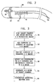
- Fig. 3 is a flow chart that schematically illustrates a method for cardiac mapping and imaging, in accordance with an embodiment of the present invention.
- the disclosed method combines multiple 2-D ultrasound images, acquired at different positions of the catheter, into a single 3-D model of the target structure.
- target structure or “target” may refer to a chamber of the heart, in whole or in part, or to a particular wall, surface, blood vessel or other anatomical feature.
- the embodiments described herein refer particularly to structures in and around the heart, the principles of the present invention may similarly be applied, mutatis mutandis, in imaging of bones, muscles and other organs and anatomical structures.
- the method begins with acquisition of a sequence of 2-D ultrasound images of the target structure, at an ultrasound scanning step 50.
- the physician inserts catheter 28 through a suitable blood vessel into a chamber of the heart, such as the right atrium, and then scans the target structure by moving the catheter between different positions inside the chamber.
- the target structure may comprise all or a part of the chamber in which the catheter is located or, additionally or alternatively, a different chamber, such as the left atrium, or vascular structures, such as the aorta.
- the image processor acquires and produces a 2-D ultrasound image, such as the image shown in Fig. 4 below.
- the positioning sub-system measures and calculates the position of the catheter.
- the calculated position is stored together with the corresponding ultrasound image.
- each position of the catheter is represented in coordinate form, such as a six-dimensional coordinate (X, Y, Z axis positions and pitch, yaw and roll angular orientations).
- the catheter performs additional measurements using electrode 46.
- the measured parameters such as local electrical potentials, are optionally overlaid and displayed as an additional layer on the reconstructed 3-D model of the target structure, as will be explained below.
- the image processor displays one or more of these images to the physician, at a manual tagging step 52.
- step 52 may be interleaved with step 50.
- the gray levels in the images enable the physician to identify structures, such as the walls of heart chambers, blood vessels and valves.
- the physician examines the ultrasound images and identifies contours-of-interest that represent walls or boundaries of the target structure.
- the physician marks the contours on display 44, typically by "tagging" them using a pointing device 45, such as a trackball.
- the pointing device may alternatively comprise a mouse, a touch-sensitive screen or tablet coupled to display 44, or any other suitable input device.
- display 44 and pointing device 45 is an example of an interactive display, i.e., means for presenting an image and permitting the user to mark on the image in such a way that a computer is able to locate the marks in the image.
- an interactive display i.e., means for presenting an image and permitting the user to mark on the image in such a way that a computer is able to locate the marks in the image.
- Other types of interactive displays will be apparent to those skilled in the art.
- the physician may tag the contours on one or several images out of the set in this manner.
- the physician may also tag various anatomical landmarks or artifacts, as relevant to the medical procedure in question.
- the physician may similarly identify "keep away" areas that should not be touched or entered in a subsequent therapeutic procedure, such as ablation.
- the contours-of-interest are tagged in a semi-automatic manner.
- the image processor may run suitable contour detection software.
- the software automatically detects and marks contours in one or more of the 2-D images. The physician then reviews and edits the automatically-detected contours using the interactive display.
- the image processor may use the tagged contours to automatically reconstruct the contours in the remaining, untagged ultrasound images, at an automatic tagging step 54.
- the physician may tag all 2-D ultrasound images at step 52. In this case, step 54 is omitted.
- the image processor traces the structures tagged by the physician, and reconstructs them in the remaining ultrasound images. This identification and reconstruction process may use any suitable image processing method, including edge detection methods, correlation methods, motion detection methods and other methods known in the art.
- the position coordinates of the catheter that are associated with each of the images may also be used by the image processor in correlating the contour locations from image to image.
- step 54 may be implemented in a user-assisted manner, in which the physician reviews and corrects the automatic contour reconstruction carried out by the image processor.
- the output of step 54 is a set of 2-D ultrasound images, tagged with the contours-of-interest.
- the image processor subsequently assigns 3-D coordinates to the contours-of-interest identified in the set of images, at a 3-D coordinate assignment step 56.
- the physician marks the tags on 2-D images, the location and orientation of the planes of these images in 3-D space are known by virtue of the positional information, stored together with the images at step 50. Therefore, the image processor is able to determine the 3-D coordinates for each pixel or of any pixel in the 2-D images, and in particular those corresponding to the tagged contours.
- the image processor typically uses the stored calibration data comprising the position and orientation offsets between the position sensor and the ultrasonic sensor, as described above.
- the contours-of-interest comprise discrete points.
- the positioning processor assigns a 3-D coordinate to each such discrete point. Additionally, the positioning processor assigns a 3-D coordinate to discrete points of a surface or a volume (defined by surfaces) such as a chamber of a heart.
- registration of the pre-acquired image to the one or more 2-D ultrasound images or 3-D model of the ultrasound images can be performed using contours, discrete points, surfaces or volumes.
- the image processor displays one or more of the 2-D ultrasound images, appropriately oriented in 3-D space. (See, for example, Fig. 6 below.)
- the contours-of-interest may optionally be marked on the oriented 2-D image.
- the image processor produces a 3-D skeleton model of the target structure, at a 3-D reconstruction step 58.
- the image processor arranges the tagged contours from some or all of the 2-D images in 3-D space to form the skeleton model. (See an exemplary skeleton model in Fig. 7 below.)
- the image processor uses a "wire-mesh" type process to generate surfaces over the skeleton model and produce a solid 3-D shape of the target structure.
- the image processor projects the contours-of-interest on the generated 3-D model.
- the model is typically presented to the physician on display 44. (See exemplary 3-D models in Figs. 8-10 below).
- system 20 supports a measurement of local electrical potentials on the surfaces of the target structure.
- each electrical activity data-point acquired by catheter 28 comprises an electrical potential or activation time value measured by electrode 46 and the corresponding position coordinates of the catheter measured by the positioning sub-system for creation or generation of an electrophysiological map (by the image processor).
- the image processor registers the electrical activity data-points with the coordinate system of the 3-D model and overlays them on the model, at an overlaying step 60. Step 60 is optional in the method and is performed only if system 20 supports this type of measurement and if the physician has chosen to use this feature.
- the electrical activity data-points are typically measured when electrode 46 is in contact with, or in close proximity to, the wall of the target structure. Therefore, the data-points are typically superimposed on the 3-D model of the structure.
- a separate 3-D electrical activity map (often referred to as an electro-anatomical map) can be generated and displayed.
- a suitable electro-anatomical map can be produced by a CARTO TM navigation and mapping system, manufactured and sold by Biosense Webster, Inc. (Diamond Bar, California).
- the electrical potential values may be presented using a color scale, for example, or any other suitable visualization method.
- the image processor may interpolate or extrapolate the measured electrical potential values and display a full color map that describes the potential distribution across the walls of the target structure.
- the term "electrophysiological map” means a map of electrical activity data-points or an electro-anatomical map.
- CT computerized tomography
- MRI magnetic resonance imaging
- x-ray information may be registered with the 3-D ultrasound-based model and displayed together with the 3-D model and/or with 2-D ultrasound images on display 44.
- CT computerized tomography
- MRI magnetic resonance imaging
- x-ray information may be registered with the 3-D ultrasound-based model and displayed together with the 3-D model and/or with 2-D ultrasound images on display 44.
- the order of steps 50-60 may be modified, and steps may be repeated in an interactive manner.
- the physician may acquire a first sequence 2-D images and tag them manually. Then, the physician may go back and acquire additional images and have the system tag them automatically, using the tagged contours in the first sequence of images. The physician may then generate the full 3-D model and examine it. If the model is not accurate enough in some areas, the physician may decide to acquire an additional set of images in order to refine the 3-D model. Additionally or alternatively, the physician may decide, after examining the images or the 3-D model, to change the manual tagging of one or more of the images, or to override the automatic tagging process.
- Other sequences of applying steps 50-60, in order to reach a high quality 3-D model of the target structure may also be followed by the physician. Additionally or alternatively, some of these steps may be carried out automatically, under robotic control, for example.
- features from the 2-D ultrasound images are selectively displayed as part of the 3-D model. For example, features that are located outside the volume defined by the contours-of-interest may be discarded or hidden from the displayed model. Alternatively or additionally, only the skeleton model or the wire-mesh model can be displayed. Other suitable criteria can be used for filtering the information to be displayed. For example, "keep away" areas marked in one or more of the 2-D images, as described above, may be suitably drawn and highlighted in the 3-D model.
- system 20 can be used as a real-time or near real-time imaging system.
- the physician can reconstruct a 3-D model of the target structure using the methods described above, as a preparatory step before beginning a medical procedure.
- the physician can tag any desired anatomical landmarks or features of interest, which are displayed on the 3-D model.
- system 20 can continuously track and display the 3-D position of the catheter with respect to the model and the tagged contours.
- the catheter used for performing the medical procedure may be the same catheter used for generating the 3-D model, or a different catheter fitted with a suitable position sensor.
- Figs. 4-8 are images that visually demonstrate the 3-D imaging method described above, in accordance with an embodiment of the present invention.
- the figures were produced from ultrasound images generated by a cardiac imaging system implemented by the inventors. The images were produced during a real-life experiment that imaged the heart of a pig using a catheter similar to the catheter shown in Fig. 2 above.
- Fig. 4 shows a 2-D ultrasound image acquired by the ultrasonic transducers at a particular position of catheter 28.
- the image shows two distinct features 80 and 82 of the heart. Multiple ultrasound images of this form were acquired at different positions of the catheter, in accordance with ultrasound scanning step 50 of the method of Fig. 3 above.
- Fig. 5 shows the ultrasound image of Fig. 4 , with features 80 and 82 marked with contours 84 and 86, respectively.
- Fig 4 was taken with the catheter positioned in the right atrium.
- feature 80 represents the mitral valve
- feature 82 represent the aortic valve.
- the contours were manually tagged by a user, in accordance with manual tagging step 52 of the method of Fig. 3 above.
- Contours 84 and 86 mark the anatomical structures in the 3-D working volume and assist the physician to identify these structures during the procedure.
- Fig. 6 shows a 2-D ultrasound image 85 oriented and projected in 3-D space.
- the figure shows an exemplary split-screen display, as can be produced by image processor 42 and displayed on display 44 of system 20.
- the "raw" 2-D image is displayed in a separate window on the right hand side of the figure.
- An isometric display at the center of the figure shows a projected image 87, produced by orienting and projecting the plane of image 85 in 3-D space, in accordance with the position measurement of position sensor 32.
- An orientation icon 81 typically having the shape of the imaged anatomical structure (a heart in this example), is displayed with the same orientation as projected image 87 in real-time as catheter 28 is moved within the patient's body. Icon 81 assists the physician in understanding the 3-D orientation of the projected image.
- a beam icon 83 is used in association with projected 2-D image 87 to mark the area scanned by the ultrasound beam.
- icon 83 is oriented and displayed in the same plane (same orientation) as projected image 87 in real-time as catheter 28 is moved within the patient's body.
- Icon 83 may comprise a web-like or fan-like linear depiction, preferably in color, such as red.
- icon 83 may comprise a colored line marking the perimeter of the area scanned by the beam to produce image 87, or any other suitable means for visualizing the position and orientation of the ultrasound beam.
- icon 83 comprises two straight lines indicating the angular sector defined by the ultrasound beam.
- an additional icon 99 marking the location and position of the distal end of catheter 28 is also displayed.
- the distal end of catheter 28 is displayed as a catheter tip icon 99 that permits the physician or user of system 20 to understand the location and orientation of ultrasound images captured by the catheter 28, independently of whether any other image processing is used to orient the 2-D ultrasound image or fan 87 or to superimpose the 2-D image on a 3-D image or frame.
- the physician or user of suystem 20 may also use the icon 99 for aiming or directing the ultrasound beam in a desired direction and/orientation.
- the catheter tip icon 99 may be used in positioning the tip of catheter 28 adjacent to a known landmark in the heart in order to facilitate a more accurate estimation of the direction of the ultrasound beam.
- Projected image 87 is typically displayed inside a cube that marks the boundaries of the working volume.
- the working volume is typically referenced to the coordinate system of field radiating coils 30 of the positioning sub-system shown in Fig. 1 above.
- each side of the cube i.e., the characteristic dimension of the working volume
- any other suitable size and shape can be chosen for the working volume, typically depending upon the tissue penetration capability of the ultrasound beam.
- a signal display 91 at the bottom of the figure shows the ECG signal, to which the measurements are synchronized, as explained above.
- the position and orientation of the projected image and of icon 83 change with the movements of catheter 28.
- the physician can change the angle of observation, zoom in and out and otherwise manipulate the displayed images using the interactive display.
- the user interface features described herein are shown as an exemplary configuration. Any other suitable user interface can be used.
- system 20 and the associated user interface can be used for 3-D display and projection of 2-D ultrasound images, without reconstructing a 3-D model.
- the physician can acquire a single 2-D ultrasound image and tag contours-of-interest on this image.
- System 20 can then orient and project the ultrasound image in 3-D space, in a manner similar to the presentation of projected image 87.
- the system can continuously track and display the 3-D position of the catheter performing the procedure (which may be different from the catheter acquiring image 87) with respect to the projected ultrasound image and the tagged contours.
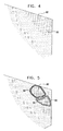
- Fig. 7 shows a skeleton model of the target structure, in this example comprising the right ventricle, produced by the image processor in accordance with 3-D reconstruction step 58 of the method of Fig. 3 above.
- the image processor Prior to generating the skeleton model, the image processor traced and reconstructed contours 84 and 86 in the untagged ultrasound images, in accordance with automatic tagging step 54.
- Fig. 7 shows the original contours 84 and 86 projected onto 3-D space. Contours 88 were automatically reconstructed by the image processor from other contours tagged by the physician.
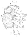
- Fig. 8 shows a solid 3-D model of the right ventricle, generated by the image processor. Some of contours 88 are overlaid on the solid model. In addition, contours 89 showing the left ventricle can also be seen in the figure.
- the surface of the right ventricle is overlaid with an electrical activity map 90, as measured by electrode 46 in accordance with overlaying step 60 of the method of Fig. 3 above.
- the map presents different electrical potential values using different colors (shown as different shading patterns in Fig. 8 ).
- Figs. 9 and 10 are images that visually demonstrate modeled left atria, in accordance with an embodiment of the present invention.
- the atrium is shown as a solid model 92.
- a contour 94 tagged by the physician marks the location of the fossa ovalis.
- Contours 96 mark additional contours of interest used to construct solid model 92.
- a 2-D ultrasound image 98 is registered with the coordinate system of model 92 and displayed together with the model.
- Fig. 11 is an image that visually demonstrates an ultrasound image 102 registered with a pre-acquired image 100, in accordance with an embodiment of the present invention.
- a pre-acquired CT image is registered with the coordinate system of the 3-D model.
- the pre-acquired image and the 2-D ultrasound image are displayed together on display 44.
- the principles of the present invention may also be applied in reconstructing 3-D models of organs using an external or internal ultrasound probe (such as a trans-thoracic probe), fitted with a positioning sensor.
- the disclosed method may be used for 3-D modeling of organs other than the heart.
- other diagnostic or treatment information such as tissue thickness and ablation temperature, may be overlaid on the 3-D model in the manner of the electrical activity overlay described above.
- the 3-D model may also be used in conjunction with other diagnostic or surgical procedures, such as ablation catheters.
- the 3-D model may also be used in conjunction with other procedures, such as an atrial septal defect closing procedure, spine surgery, and particularly minimally-invasive procedures.
Claims (13)
- Medizinisches Bildgebungssystem (20) zum Abbilden eines Zielobjekts in dem Körper eines Patienten, wobei das Zielobjekt eine oder mehrere Eigenschaften besitzt, wobei das System Folgendes umfasst:einen Katheter (28), der einen Positionssensor (32) und einen Ultraschallbildgebungssensor (40) umfasst, wobei der Positionssensor konfiguriert ist, elektrische Signale, die Positionsinformationen eines Teils des Katheters in dem Körper des Patienten angeben, zu übertragen, und der Ultraschallbildgebungssensor konfiguriert ist, Ultraschallenergie an das Zielobjekt in dem Körper des Patienten zu übertragen, von dem Zielobjekt in dem Körper des Patienten reflektierte Ultraschallechos zu empfangen und Signale bezüglich der von dem Zielobjekt in dem Körper des Patienten reflektierten Ultraschallechos zu übertragen;gekennzeichnet durcheinen Positionierungsprozessor (36), der mit dem Katheter betriebstechnisch verbunden ist, um Positionsinformationen des Teils des Katheters aufgrund der durch den Positionssensor übertragenen elektrischen Signale zu bestimmen;eine Anzeige (44), die konfiguriert ist, einem Anwender des Systems zu ermöglichen, interessierende Konturen auf einem oder mehreren zweidimensionalen auf der Anzeige gezeigten Ultraschallbildern zu markieren, wobei die Konturen die Eigenschaften des Zielobjekts identifizieren; undeinen Bildprozessor (42), der mit dem Katheter, dem Positionierungsprozessor und der Anzeige betriebstechnisch verbunden ist, wobei der Bildprozessor konfiguriert ist:(i) mehrere zweidimensionale Ultraschallbilder (102) des Zielobjekts aufgrund der durch den Ultraschallsensor übertragenen Signale zu erzeugen; dreidimensionale Koordinaten für jedes Pixel des Ultraschallbildes des Zielobjekts aufgrund der Positionsinformationen zu bestimmen und eine Gruppe von zweidimensionalen Ultraschallbildern, die mit interessierenden Konturen markiert sind, auszugeben;(ii) ein dreidimensionales Skelettmodell unter Verwendung der mehreren zweidimensionalen Ultraschallbilder zu rekonstruieren, indem anschließend dreidimensionale Koordinaten den markierten interessierenden Konturen, die in der Gruppe der zweidimensionalen Ultraschallbilder identifiziert wurden, zugeordnet werden und die markierten Konturen von einigen oder allen der zweidimensionalen Ultraschallbilder in einem dreidimensionalen Raum angeordnet werden, um ein Skelettmodell zu bilden; und(iii) ein zweidimensionales Echtzeit-Ultraschallbild auf dem dreidimensionalen Modell auf der Anzeige in derselben Orientierung wie eine Orientierung des Teils des Katheters in dem Körper des Patienten aufgrund von von dem Positionssensor abgeleiteten Positionsinformationen darzustellen.
- System nach Anspruch 1, wobei die interessierenden Konturen in einem ersten der mehreren zweidimensionalen Ultraschallbilder markiert sind und der Bildprozessor ferner konfiguriert ist, entsprechende Konturen in zumindest einigen der nicht markierten verbleibenden mehreren zweidimensionalen Ultraschallbilder automatisch zu identifizieren und zu rekonstruieren.
- System nach Anspruch 2, wobei der Bildprozessor ferner konfiguriert ist, entsprechende Konturen aufgrund einer Anwendereingabe von einer oder mehreren von: Genehmigung, Löschung, Korrektur und Änderung zu rekonstruieren.
- System nach Anspruch 1, das ferner ein vorerfasstes Bild (100) umfasst; wobei:der Bildprozessor ferner konfiguriert ist, das vorerfasste Bild mit einem der durch den Ultraschallsensor übertragenen Ultraschallbilder und dem dreidimensionalen Modell zu registrieren.
- System nach einem der Ansprüche 1 bis 4, wobei die Orientierung des zweidimensionalen Echtzeitultraschallbildes als dieselbe Orientierung des Teils des Katheters in Echtzeit auf der Anzeige dargestellt wird, wenn der Katheter innerhalb des Körpers des Patienten bewegt wird.
- System nach Anspruch 5, das ferner ein Strahlsymbol (83) umfasst, um die Orientierung des zweidimensionalen Echtzeit-Ultraschallbildes in derselben Orientierung des Teils des Katheters in Echtzeit darzustellen.
- System nach Anspruch 6, das ferner ein Orientierungssymbol (81) umfasst, das auf der Anzeige in derselben Orientierung wie das auf der Anzeige dargestellte zweidimensionale Echtzeit-Ultraschalbild dargestellt wird.
- System nach Anspruch 6, wobei das Strahlsymbol auf der Anzeige in einer Farbe dargestellt wird.
- System nach Anspruch 8, wobei das Strahlsymbol eine netzartige Darstellung ist.
- System nach Anspruch 8, wobei das Strahlsymbol eine fächerartige Darstellung ist.
- System nach Anspruch 7, wobei das Orientierungssymbol eine Form des Zielobjekts, das mit dem Katheter dargestellt ist, umfasst.
- System nach Anspruch 11, wobei das Zielobjekt eine anatomische Struktur umfasst.
- System nach einem vorhergehenden Anspruch, wobei der Bildprozessor ferner konfiguriert ist, Flächen über dem Skelettmodell unter Verwendung eines Drahtnetzvorgangs zu erzeugen, um eine dreidimensionale Vollform zu erzeugen.
Applications Claiming Priority (1)
| Application Number | Priority Date | Filing Date | Title |
|---|---|---|---|
| US11/114,680 US8870779B2 (en) | 2005-04-26 | 2005-04-26 | Display of two-dimensional ultrasound fan |
Publications (3)
| Publication Number | Publication Date |
|---|---|
| EP1720039A2 EP1720039A2 (de) | 2006-11-08 |
| EP1720039A3 EP1720039A3 (de) | 2008-02-20 |
| EP1720039B1 true EP1720039B1 (de) | 2014-12-03 |
Family
ID=36694319
Family Applications (1)
| Application Number | Title | Priority Date | Filing Date |
|---|---|---|---|
| EP06252210.7A Active EP1720039B1 (de) | 2005-04-26 | 2006-04-25 | Darstellung eines zweidimensionalen fächerförmigen Ultraschallfeldes |
Country Status (10)
| Country | Link |
|---|---|
| US (1) | US8870779B2 (de) |
| EP (1) | EP1720039B1 (de) |
| JP (1) | JP5265091B2 (de) |
| KR (1) | KR20060112243A (de) |
| CN (1) | CN1853575B (de) |
| AU (1) | AU2006201645A1 (de) |
| BR (1) | BRPI0601507A (de) |
| CA (1) | CA2544118C (de) |
| IL (1) | IL175188A (de) |
| MX (1) | MXPA06004651A (de) |
Families Citing this family (80)
| Publication number | Priority date | Publication date | Assignee | Title |
|---|---|---|---|---|
| US8784336B2 (en) | 2005-08-24 | 2014-07-22 | C. R. Bard, Inc. | Stylet apparatuses and methods of manufacture |
| EP1923839B1 (de) * | 2006-11-14 | 2016-07-27 | Hitachi Aloka Medical, Ltd. | Ultraschall-Diagnosegerät und Verfahren zur Verarbeitung von Volumendaten |
| US7831076B2 (en) * | 2006-12-08 | 2010-11-09 | Biosense Webster, Inc. | Coloring electroanatomical maps to indicate ultrasound data acquisition |
| IL188569A (en) * | 2007-01-17 | 2014-05-28 | Mediguide Ltd | Method and system for coordinating a 3D image coordinate system with a medical position coordinate system and a 2D image coordinate system |
| US9629571B2 (en) | 2007-03-08 | 2017-04-25 | Sync-Rx, Ltd. | Co-use of endoluminal data and extraluminal imaging |
| JP5639764B2 (ja) | 2007-03-08 | 2014-12-10 | シンク−アールエックス,リミティド | 運動する器官と共に使用するイメージング及びツール |
| US11197651B2 (en) | 2007-03-08 | 2021-12-14 | Sync-Rx, Ltd. | Identification and presentation of device-to-vessel relative motion |
| US9375164B2 (en) | 2007-03-08 | 2016-06-28 | Sync-Rx, Ltd. | Co-use of endoluminal data and extraluminal imaging |
| US11064964B2 (en) | 2007-03-08 | 2021-07-20 | Sync-Rx, Ltd | Determining a characteristic of a lumen by measuring velocity of a contrast agent |
| US9968256B2 (en) | 2007-03-08 | 2018-05-15 | Sync-Rx Ltd. | Automatic identification of a tool |
| US10716528B2 (en) | 2007-03-08 | 2020-07-21 | Sync-Rx, Ltd. | Automatic display of previously-acquired endoluminal images |
| EP2358269B1 (de) | 2007-03-08 | 2019-04-10 | Sync-RX, Ltd. | Bildverarbeitung und instrumentbetätigung für medizinische verfahren |
| US8700130B2 (en) | 2007-03-08 | 2014-04-15 | Sync-Rx, Ltd. | Stepwise advancement of a medical tool |
| US7909767B2 (en) * | 2007-05-16 | 2011-03-22 | General Electric Company | Method for minimizing tracking system interference |
| US8057397B2 (en) * | 2007-05-16 | 2011-11-15 | General Electric Company | Navigation and imaging system sychronized with respiratory and/or cardiac activity |
| US8527032B2 (en) * | 2007-05-16 | 2013-09-03 | General Electric Company | Imaging system and method of delivery of an instrument to an imaged subject |
| US9055883B2 (en) * | 2007-05-16 | 2015-06-16 | General Electric Company | Surgical navigation system with a trackable ultrasound catheter |
| US8790262B2 (en) * | 2007-05-16 | 2014-07-29 | General Electric Company | Method for implementing an imaging and navigation system |
| US8428690B2 (en) | 2007-05-16 | 2013-04-23 | General Electric Company | Intracardiac echocardiography image reconstruction in combination with position tracking system |
| US20080287805A1 (en) * | 2007-05-16 | 2008-11-20 | General Electric Company | System and method to guide an instrument through an imaged subject |
| US7940972B2 (en) * | 2007-05-16 | 2011-05-10 | General Electric Company | System and method of extended field of view image acquisition of an imaged subject |
| US8213693B1 (en) | 2007-05-16 | 2012-07-03 | General Electric Company | System and method to track and navigate a tool through an imaged subject |
| US8989842B2 (en) | 2007-05-16 | 2015-03-24 | General Electric Company | System and method to register a tracking system with intracardiac echocardiography (ICE) imaging system |
| US8364242B2 (en) | 2007-05-17 | 2013-01-29 | General Electric Company | System and method of combining ultrasound image acquisition with fluoroscopic image acquisition |
| CA2633231C (en) * | 2007-06-04 | 2017-03-21 | Biosense Webster, Inc. | Cardiac mechanical assessment using ultrasound |
| US9173638B2 (en) | 2007-06-04 | 2015-11-03 | Biosense Webster, Inc. | Cardiac mechanical assessment using ultrasound |
| FR2923377B1 (fr) * | 2007-11-12 | 2012-05-04 | Agnes Leteurtre | Bloc operatoire pour tele-chirurgie, utilisable meme en milieu inhospitalier |
| US10751509B2 (en) | 2007-11-26 | 2020-08-25 | C. R. Bard, Inc. | Iconic representations for guidance of an indwelling medical device |
| US10524691B2 (en) | 2007-11-26 | 2020-01-07 | C. R. Bard, Inc. | Needle assembly including an aligned magnetic element |
| US9521961B2 (en) | 2007-11-26 | 2016-12-20 | C. R. Bard, Inc. | Systems and methods for guiding a medical instrument |
| US9649048B2 (en) | 2007-11-26 | 2017-05-16 | C. R. Bard, Inc. | Systems and methods for breaching a sterile field for intravascular placement of a catheter |
| ES2651898T3 (es) | 2007-11-26 | 2018-01-30 | C.R. Bard Inc. | Sistema integrado para la colocación intravascular de un catéter |
| US10449330B2 (en) | 2007-11-26 | 2019-10-22 | C. R. Bard, Inc. | Magnetic element-equipped needle assemblies |
| US8781555B2 (en) * | 2007-11-26 | 2014-07-15 | C. R. Bard, Inc. | System for placement of a catheter including a signal-generating stylet |
| US20090177089A1 (en) * | 2008-01-04 | 2009-07-09 | Assaf Govari | Three-dimensional image reconstruction using doppler ultrasound |
| EP2108328B2 (de) | 2008-04-09 | 2020-08-26 | Brainlab AG | Bildbasiertes Ansteuerungsverfahren für medizintechnische Geräte |
| EP2291136B1 (de) | 2008-06-20 | 2012-04-25 | Koninklijke Philips Electronics N.V. | System zur Durchführung von Biopsien |
| ES2525525T3 (es) | 2008-08-22 | 2014-12-26 | C.R. Bard, Inc. | Conjunto de catéter que incluye conjuntos de sensor de ECG y magnético |
| US9974509B2 (en) | 2008-11-18 | 2018-05-22 | Sync-Rx Ltd. | Image super enhancement |
| US9101286B2 (en) | 2008-11-18 | 2015-08-11 | Sync-Rx, Ltd. | Apparatus and methods for determining a dimension of a portion of a stack of endoluminal data points |
| US11064903B2 (en) | 2008-11-18 | 2021-07-20 | Sync-Rx, Ltd | Apparatus and methods for mapping a sequence of images to a roadmap image |
| US9095313B2 (en) | 2008-11-18 | 2015-08-04 | Sync-Rx, Ltd. | Accounting for non-uniform longitudinal motion during movement of an endoluminal imaging probe |
| US10362962B2 (en) | 2008-11-18 | 2019-07-30 | Synx-Rx, Ltd. | Accounting for skipped imaging locations during movement of an endoluminal imaging probe |
| US8855744B2 (en) | 2008-11-18 | 2014-10-07 | Sync-Rx, Ltd. | Displaying a device within an endoluminal image stack |
| US9144394B2 (en) | 2008-11-18 | 2015-09-29 | Sync-Rx, Ltd. | Apparatus and methods for determining a plurality of local calibration factors for an image |
| JP5422264B2 (ja) * | 2009-06-09 | 2014-02-19 | 株式会社東芝 | 超音波診断装置及び医用画像処理装置 |
| US9445734B2 (en) | 2009-06-12 | 2016-09-20 | Bard Access Systems, Inc. | Devices and methods for endovascular electrography |
| US9532724B2 (en) | 2009-06-12 | 2017-01-03 | Bard Access Systems, Inc. | Apparatus and method for catheter navigation using endovascular energy mapping |
| CN102821679B (zh) | 2010-02-02 | 2016-04-27 | C·R·巴德股份有限公司 | 用于导管导航和末端定位的装置和方法 |
| ES2778041T3 (es) | 2010-05-28 | 2020-08-07 | Bard Inc C R | Aparato para su uso con sistema de guiado de inserción de aguja |
| EP2912999B1 (de) | 2010-05-28 | 2022-06-29 | C. R. Bard, Inc. | Vorrichtung zur Verwendung mit einem Nadeleinsatz-Führungssystem |
| WO2012024577A2 (en) | 2010-08-20 | 2012-02-23 | C.R. Bard, Inc. | Reconfirmation of ecg-assisted catheter tip placement |
| CN103687541B (zh) * | 2011-03-02 | 2017-02-15 | 皇家飞利浦有限公司 | 用于导航引导的可视化 |
| US10290076B2 (en) | 2011-03-03 | 2019-05-14 | The United States Of America, As Represented By The Secretary, Department Of Health And Human Services | System and method for automated initialization and registration of navigation system |
| JP6099640B2 (ja) | 2011-06-23 | 2017-03-22 | シンク−アールエックス,リミティド | 管腔の背景の鮮明化 |
| EP2669830A1 (de) * | 2012-06-01 | 2013-12-04 | Kabushiki Kaisha Toshiba, Inc. | Herstellung und Anzeige abgeleiteter Serien medizinischer Bilder |
| JP6134789B2 (ja) | 2012-06-26 | 2017-05-24 | シンク−アールエックス,リミティド | 管腔器官における流れに関連する画像処理 |
| WO2014075080A1 (en) | 2012-11-12 | 2014-05-15 | Image Insight Inc. | Crowd-sourced hardware calibration |
| KR101487688B1 (ko) * | 2012-11-23 | 2015-01-29 | 삼성메디슨 주식회사 | 단면의 위치를 가이드하기 위한 내비게이터를 제공하는 초음파 시스템 및 방법 |
| JP6434959B2 (ja) * | 2013-04-11 | 2018-12-05 | フィリップス メディカル システムズ テクノロジーズ リミテッド | ユーザが画像データを研究するのを可能にすること |
| CN112754463A (zh) * | 2013-07-23 | 2021-05-07 | 皇家飞利浦有限公司 | 用于定位身体结构的方法和系统 |
| CN103750860B (zh) * | 2014-01-20 | 2016-01-06 | 华南理工大学 | 一种无线三维超声成像方法和装置 |
| CN105979868B (zh) | 2014-02-06 | 2020-03-10 | C·R·巴德股份有限公司 | 用于血管内装置的导向和放置的系统和方法 |
| US10973584B2 (en) | 2015-01-19 | 2021-04-13 | Bard Access Systems, Inc. | Device and method for vascular access |
| EP3236854B1 (de) * | 2015-02-13 | 2019-11-06 | St. Jude Medical International Holding S.à r.l. | Verfolgungsbasierte 3d-modell-erweiterung |
| US10349890B2 (en) | 2015-06-26 | 2019-07-16 | C. R. Bard, Inc. | Connector interface for ECG-based catheter positioning system |
| JP6643827B2 (ja) * | 2015-07-31 | 2020-02-12 | キヤノン株式会社 | 画像処理装置、画像処理方法、及びプログラム |
| US11000207B2 (en) | 2016-01-29 | 2021-05-11 | C. R. Bard, Inc. | Multiple coil system for tracking a medical device |
| US10278656B2 (en) | 2016-05-09 | 2019-05-07 | Image Insight, Inc. | Medical devices for diagnostic imaging |
| EP3697315B1 (de) * | 2017-10-19 | 2022-01-05 | Koninklijke Philips N.V. | Digitales rotationspatientenschnittstellenmodul |
| JP7112077B2 (ja) * | 2018-09-03 | 2022-08-03 | 学校法人 久留米大学 | コントローラ、コントローラの製造方法、疑似体験システム、および疑似体験方法 |
| WO2020081373A1 (en) | 2018-10-16 | 2020-04-23 | Bard Access Systems, Inc. | Safety-equipped connection systems and methods thereof for establishing electrical connections |
| EP4226864A1 (de) * | 2018-10-26 | 2023-08-16 | Koninklijke Philips N.V. | Intraluminale ultraschallbildgebung mit automatischen und unterstützten etiketten und lesezeichen |
| IL272254B2 (en) | 2019-02-15 | 2023-04-01 | Biosense Webster Israel Ltd | Catheter for insertion through the esophagus with a carbon dioxide transfer system for thermal protection of the esophagus |
| US20210187242A1 (en) | 2019-12-23 | 2021-06-24 | Ethicon, Inc. | Fluid Delivery System for Creating Separation Between Biological Surfaces |
| US20210186642A1 (en) | 2019-12-23 | 2021-06-24 | Ethicon, Inc. | Esophageal Protection Pathways |
| US20210186601A1 (en) | 2019-12-23 | 2021-06-24 | Ethicon, Inc. | Transesophageal Catheter for Thermal Protection of the Esophagus |
| US11295468B2 (en) * | 2020-03-23 | 2022-04-05 | Biosense Webster (Israel) Ltd. | Determining an enclosing wall surface of a cavity of an organ |
| WO2022264011A1 (en) | 2021-06-14 | 2022-12-22 | Ethicon, Inc. | Catheter with carbon dioxide delivery system and methods |
| CN115836879B (zh) * | 2022-12-29 | 2024-02-23 | 苏州诺莱声科技有限公司 | 一种心腔内超声控制系统及方法 |
Family Cites Families (50)
| Publication number | Priority date | Publication date | Assignee | Title |
|---|---|---|---|---|
| US4751643A (en) * | 1986-08-04 | 1988-06-14 | General Electric Company | Method and apparatus for determining connected substructures within a body |
| US4791567A (en) * | 1986-09-15 | 1988-12-13 | General Electric Company | Three dimensional connectivity system employing an equivalence schema for determining connected substructures within a body |
| GB9025431D0 (en) * | 1990-11-22 | 1991-01-09 | Advanced Tech Lab | Three dimensional ultrasonic imaging |
| US5568384A (en) * | 1992-10-13 | 1996-10-22 | Mayo Foundation For Medical Education And Research | Biomedical imaging and analysis |
| US5601084A (en) * | 1993-06-23 | 1997-02-11 | University Of Washington | Determining cardiac wall thickness and motion by imaging and three-dimensional modeling |
| DE69432148T2 (de) * | 1993-07-01 | 2003-10-16 | Boston Scient Ltd | Katheter zur bilddarstellung, zur anzeige elektrischer signale und zur ablation |
| US5738096A (en) * | 1993-07-20 | 1998-04-14 | Biosense, Inc. | Cardiac electromechanics |
| US5391199A (en) * | 1993-07-20 | 1995-02-21 | Biosense, Inc. | Apparatus and method for treating cardiac arrhythmias |
| US5701898A (en) * | 1994-09-02 | 1997-12-30 | The United States Of America As Represented By The Department Of Health And Human Services | Method and system for Doppler ultrasound measurement of blood flow |
| US6690963B2 (en) * | 1995-01-24 | 2004-02-10 | Biosense, Inc. | System for determining the location and orientation of an invasive medical instrument |
| WO1996025882A1 (en) | 1995-02-22 | 1996-08-29 | Groenningsaeter Aage | Method for ultrasound guidance during clinical procedures |
| US5538004A (en) * | 1995-02-28 | 1996-07-23 | Hewlett-Packard Company | Method and apparatus for tissue-centered scan conversion in an ultrasound imaging system |
| US5797849A (en) * | 1995-03-28 | 1998-08-25 | Sonometrics Corporation | Method for carrying out a medical procedure using a three-dimensional tracking and imaging system |
| US5701900A (en) * | 1995-05-01 | 1997-12-30 | Cedars-Sinai Medical Center | Ultrasonic transducer orientation sensing and display apparatus and method |
| US5638819A (en) * | 1995-08-29 | 1997-06-17 | Manwaring; Kim H. | Method and apparatus for guiding an instrument to a target |
| IL125757A (en) * | 1996-02-15 | 2003-09-17 | Biosense Inc | Medical procedures and apparatus using intrabody probes |
| US6618612B1 (en) * | 1996-02-15 | 2003-09-09 | Biosense, Inc. | Independently positionable transducers for location system |
| US5848969A (en) * | 1996-10-28 | 1998-12-15 | Ep Technologies, Inc. | Systems and methods for visualizing interior tissue regions using expandable imaging structures |
| US5904651A (en) * | 1996-10-28 | 1999-05-18 | Ep Technologies, Inc. | Systems and methods for visualizing tissue during diagnostic or therapeutic procedures |
| US5810008A (en) * | 1996-12-03 | 1998-09-22 | Isg Technologies Inc. | Apparatus and method for visualizing ultrasonic images |
| US6049622A (en) * | 1996-12-05 | 2000-04-11 | Mayo Foundation For Medical Education And Research | Graphic navigational guides for accurate image orientation and navigation |
| US5846205A (en) * | 1997-01-31 | 1998-12-08 | Acuson Corporation | Catheter-mounted, phased-array ultrasound transducer with improved imaging |
| US5938616A (en) * | 1997-01-31 | 1999-08-17 | Acuson Corporation | Steering mechanism and steering line for a catheter-mounted ultrasonic transducer |
| US6045508A (en) * | 1997-02-27 | 2000-04-04 | Acuson Corporation | Ultrasonic probe, system and method for two-dimensional imaging or three-dimensional reconstruction |
| US5876345A (en) * | 1997-02-27 | 1999-03-02 | Acuson Corporation | Ultrasonic catheter, system and method for two dimensional imaging or three-dimensional reconstruction |
| US6019725A (en) * | 1997-03-07 | 2000-02-01 | Sonometrics Corporation | Three-dimensional tracking and imaging system |
| US5961460A (en) | 1997-04-11 | 1999-10-05 | Acuson Corporation | Ultrasound imaging enhancement methods and systems |
| US6106466A (en) | 1997-04-24 | 2000-08-22 | University Of Washington | Automated delineation of heart contours from images using reconstruction-based modeling |
| US6490474B1 (en) | 1997-08-01 | 2002-12-03 | Cardiac Pathways Corporation | System and method for electrode localization using ultrasound |
| GB2329708B (en) * | 1997-09-24 | 2002-05-08 | Roke Manor Research | Catheter localisation system |
| EP0961135B1 (de) | 1998-03-30 | 2002-11-20 | TomTec Imaging Systems GmbH | Verfahren und Vorrichtung zur Bild-Aufnahme mit Ultraschall |
| US6066096A (en) * | 1998-05-08 | 2000-05-23 | Duke University | Imaging probes and catheters for volumetric intraluminal ultrasound imaging and related systems |
| US6168564B1 (en) | 1998-10-02 | 2001-01-02 | Sci-Med Life Systems, Inc. | Steerable transducer array for intracardial ultrasonic imaging |
| US6226542B1 (en) * | 1998-07-24 | 2001-05-01 | Biosense, Inc. | Three-dimensional reconstruction of intrabody organs |
| US6950689B1 (en) | 1998-08-03 | 2005-09-27 | Boston Scientific Scimed, Inc. | Dynamically alterable three-dimensional graphical model of a body region |
| US6059731A (en) * | 1998-08-19 | 2000-05-09 | Mayo Foundation For Medical Education And Research | Simultaneous side-and-end viewing underfluid catheter |
| US6443894B1 (en) * | 1999-09-29 | 2002-09-03 | Acuson Corporation | Medical diagnostic ultrasound system and method for mapping surface data for three dimensional imaging |
| US6530885B1 (en) * | 2000-03-17 | 2003-03-11 | Atl Ultrasound, Inc. | Spatially compounded three dimensional ultrasonic images |
| US6716166B2 (en) * | 2000-08-18 | 2004-04-06 | Biosense, Inc. | Three-dimensional reconstruction using ultrasound |
| US6491636B2 (en) * | 2000-12-07 | 2002-12-10 | Koninklijke Philips Electronics N.V. | Automated border detection in ultrasonic diagnostic images |
| JP4614548B2 (ja) | 2001-01-31 | 2011-01-19 | パナソニック株式会社 | 超音波診断装置 |
| US6773402B2 (en) * | 2001-07-10 | 2004-08-10 | Biosense, Inc. | Location sensing with real-time ultrasound imaging |
| US7020512B2 (en) * | 2002-01-14 | 2006-03-28 | Stereotaxis, Inc. | Method of localizing medical devices |
| DE10210650B4 (de) | 2002-03-11 | 2005-04-28 | Siemens Ag | Verfahren zur dreidimensionalen Darstellung eines Untersuchungsbereichs eines Patienten in Form eines 3D-Rekonstruktionsbilds und medizinische Untersuchungs- und/oder Behandlungseinrichtung |
| US7477763B2 (en) | 2002-06-18 | 2009-01-13 | Boston Scientific Scimed, Inc. | Computer generated representation of the imaging pattern of an imaging device |
| US20040068178A1 (en) * | 2002-09-17 | 2004-04-08 | Assaf Govari | High-gradient recursive locating system |
| US7306593B2 (en) * | 2002-10-21 | 2007-12-11 | Biosense, Inc. | Prediction and assessment of ablation of cardiac tissue |
| DE602004029696D1 (de) | 2003-09-29 | 2010-12-02 | Koninkl Philips Electronics Nv | Ultraschallquantifizierung des herzvolumens |
| JP4681857B2 (ja) | 2004-11-25 | 2011-05-11 | オリンパス株式会社 | 超音波診断装置 |
| US7604601B2 (en) * | 2005-04-26 | 2009-10-20 | Biosense Webster, Inc. | Display of catheter tip with beam direction for ultrasound system |
-
2005
- 2005-04-26 US US11/114,680 patent/US8870779B2/en active Active
-
2006
- 2006-04-19 CA CA2544118A patent/CA2544118C/en active Active
- 2006-04-20 AU AU2006201645A patent/AU2006201645A1/en not_active Abandoned
- 2006-04-25 MX MXPA06004651A patent/MXPA06004651A/es not_active Application Discontinuation
- 2006-04-25 JP JP2006121003A patent/JP5265091B2/ja active Active
- 2006-04-25 EP EP06252210.7A patent/EP1720039B1/de active Active
- 2006-04-25 IL IL175188A patent/IL175188A/en active IP Right Grant
- 2006-04-26 CN CN2006100770878A patent/CN1853575B/zh active Active
- 2006-04-26 BR BRPI0601507-7A patent/BRPI0601507A/pt not_active IP Right Cessation
- 2006-04-26 KR KR1020060037640A patent/KR20060112243A/ko not_active Application Discontinuation
Also Published As
| Publication number | Publication date |
|---|---|
| CA2544118A1 (en) | 2006-10-26 |
| KR20060112243A (ko) | 2006-10-31 |
| CN1853575A (zh) | 2006-11-01 |
| CN1853575B (zh) | 2011-09-07 |
| AU2006201645A1 (en) | 2006-11-09 |
| EP1720039A2 (de) | 2006-11-08 |
| IL175188A (en) | 2011-11-30 |
| US8870779B2 (en) | 2014-10-28 |
| BRPI0601507A (pt) | 2006-12-26 |
| MXPA06004651A (es) | 2007-02-08 |
| CA2544118C (en) | 2014-11-25 |
| IL175188A0 (en) | 2006-09-05 |
| JP2006305360A (ja) | 2006-11-09 |
| US20060253029A1 (en) | 2006-11-09 |
| EP1720039A3 (de) | 2008-02-20 |
| JP5265091B2 (ja) | 2013-08-14 |
Similar Documents
| Publication | Publication Date | Title |
|---|---|---|
| EP1720039B1 (de) | Darstellung eines zweidimensionalen fächerförmigen Ultraschallfeldes | |
| EP1717602B1 (de) | Ultraschallkatheter mit geometrisch korrespondierender Überlagerung von elektroanatomischen und vorher erfassten Bilddaten | |
| EP3199977B1 (de) | Registrierung von ultraschalldaten mit vorher erfassten bildern | |
| AU2006201646B2 (en) | Display of catheter tip with beam direction for ultrasound system | |
| EP1717759A1 (de) | Softwareprodukt für dreidimensionale Herzbildgebung mittels Ultraschall-Konturenrekonstruktion | |
| EP1717758A2 (de) | Dreidimensionale Herzbildgebung mittels Ultraschall-Konturenrekonstruktion | |
| AU2012258444B2 (en) | Display of two-dimensional ultrasound fan | |
| IL175190A (en) | Electro-anatomical map drawing with an image previously obtained using ultrasound |
Legal Events
| Date | Code | Title | Description |
|---|---|---|---|
| PUAI | Public reference made under article 153(3) epc to a published international application that has entered the european phase |
Free format text: ORIGINAL CODE: 0009012 |
|
| AK | Designated contracting states |
Kind code of ref document: A2 Designated state(s): AT BE BG CH CY CZ DE DK EE ES FI FR GB GR HU IE IS IT LI LT LU LV MC NL PL PT RO SE SI SK TR |
|
| AX | Request for extension of the european patent |
Extension state: AL BA HR MK YU |
|
| REG | Reference to a national code |
Ref country code: HK Ref legal event code: DE Ref document number: 1097913 Country of ref document: HK |
|
| PUAL | Search report despatched |
Free format text: ORIGINAL CODE: 0009013 |
|
| AK | Designated contracting states |
Kind code of ref document: A3 Designated state(s): AT BE BG CH CY CZ DE DK EE ES FI FR GB GR HU IE IS IT LI LT LU LV MC NL PL PT RO SE SI SK TR |
|
| AX | Request for extension of the european patent |
Extension state: AL BA HR MK YU |
|
| 17P | Request for examination filed |
Effective date: 20080728 |
|
| 17Q | First examination report despatched |
Effective date: 20080903 |
|
| AKX | Designation fees paid |
Designated state(s): AT BE BG CH CY CZ DE DK EE ES FI FR GB GR HU IE IS IT LI LT LU LV MC NL PL PT RO SE SI SK TR |
|
| REG | Reference to a national code |
Ref country code: HK Ref legal event code: WD Ref document number: 1097913 Country of ref document: HK |
|
| GRAP | Despatch of communication of intention to grant a patent |
Free format text: ORIGINAL CODE: EPIDOSNIGR1 |
|
| INTG | Intention to grant announced |
Effective date: 20140805 |
|
| GRAS | Grant fee paid |
Free format text: ORIGINAL CODE: EPIDOSNIGR3 |
|
| GRAA | (expected) grant |
Free format text: ORIGINAL CODE: 0009210 |
|
| AK | Designated contracting states |
Kind code of ref document: B1 Designated state(s): AT BE BG CH CY CZ DE DK EE ES FI FR GB GR HU IE IS IT LI LT LU LV MC NL PL PT RO SE SI SK TR |
|
| REG | Reference to a national code |
Ref country code: GB Ref legal event code: FG4D |
|
| REG | Reference to a national code |
Ref country code: CH Ref legal event code: EP Ref country code: AT Ref legal event code: REF Ref document number: 699680 Country of ref document: AT Kind code of ref document: T Effective date: 20141215 |
|
| REG | Reference to a national code |
Ref country code: IE Ref legal event code: FG4D |
|
| REG | Reference to a national code |
Ref country code: DE Ref legal event code: R096 Ref document number: 602006043858 Country of ref document: DE Effective date: 20150108 |
|
| REG | Reference to a national code |
Ref country code: NL Ref legal event code: T3 |
|
| REG | Reference to a national code |
Ref country code: AT Ref legal event code: MK05 Ref document number: 699680 Country of ref document: AT Kind code of ref document: T Effective date: 20141203 |
|
| PG25 | Lapsed in a contracting state [announced via postgrant information from national office to epo] |
Ref country code: FI Free format text: LAPSE BECAUSE OF FAILURE TO SUBMIT A TRANSLATION OF THE DESCRIPTION OR TO PAY THE FEE WITHIN THE PRESCRIBED TIME-LIMIT Effective date: 20141203 Ref country code: LT Free format text: LAPSE BECAUSE OF FAILURE TO SUBMIT A TRANSLATION OF THE DESCRIPTION OR TO PAY THE FEE WITHIN THE PRESCRIBED TIME-LIMIT Effective date: 20141203 Ref country code: ES Free format text: LAPSE BECAUSE OF FAILURE TO SUBMIT A TRANSLATION OF THE DESCRIPTION OR TO PAY THE FEE WITHIN THE PRESCRIBED TIME-LIMIT Effective date: 20141203 |
|
| REG | Reference to a national code |
Ref country code: LT Ref legal event code: MG4D |
|
| PG25 | Lapsed in a contracting state [announced via postgrant information from national office to epo] |
Ref country code: SE Free format text: LAPSE BECAUSE OF FAILURE TO SUBMIT A TRANSLATION OF THE DESCRIPTION OR TO PAY THE FEE WITHIN THE PRESCRIBED TIME-LIMIT Effective date: 20141203 Ref country code: AT Free format text: LAPSE BECAUSE OF FAILURE TO SUBMIT A TRANSLATION OF THE DESCRIPTION OR TO PAY THE FEE WITHIN THE PRESCRIBED TIME-LIMIT Effective date: 20141203 Ref country code: GR Free format text: LAPSE BECAUSE OF FAILURE TO SUBMIT A TRANSLATION OF THE DESCRIPTION OR TO PAY THE FEE WITHIN THE PRESCRIBED TIME-LIMIT Effective date: 20150304 Ref country code: CY Free format text: LAPSE BECAUSE OF FAILURE TO SUBMIT A TRANSLATION OF THE DESCRIPTION OR TO PAY THE FEE WITHIN THE PRESCRIBED TIME-LIMIT Effective date: 20141203 Ref country code: LV Free format text: LAPSE BECAUSE OF FAILURE TO SUBMIT A TRANSLATION OF THE DESCRIPTION OR TO PAY THE FEE WITHIN THE PRESCRIBED TIME-LIMIT Effective date: 20141203 |
|
| PG25 | Lapsed in a contracting state [announced via postgrant information from national office to epo] |
Ref country code: PT Free format text: LAPSE BECAUSE OF FAILURE TO SUBMIT A TRANSLATION OF THE DESCRIPTION OR TO PAY THE FEE WITHIN THE PRESCRIBED TIME-LIMIT Effective date: 20150403 Ref country code: CZ Free format text: LAPSE BECAUSE OF FAILURE TO SUBMIT A TRANSLATION OF THE DESCRIPTION OR TO PAY THE FEE WITHIN THE PRESCRIBED TIME-LIMIT Effective date: 20141203 Ref country code: SK Free format text: LAPSE BECAUSE OF FAILURE TO SUBMIT A TRANSLATION OF THE DESCRIPTION OR TO PAY THE FEE WITHIN THE PRESCRIBED TIME-LIMIT Effective date: 20141203 Ref country code: EE Free format text: LAPSE BECAUSE OF FAILURE TO SUBMIT A TRANSLATION OF THE DESCRIPTION OR TO PAY THE FEE WITHIN THE PRESCRIBED TIME-LIMIT Effective date: 20141203 Ref country code: RO Free format text: LAPSE BECAUSE OF FAILURE TO SUBMIT A TRANSLATION OF THE DESCRIPTION OR TO PAY THE FEE WITHIN THE PRESCRIBED TIME-LIMIT Effective date: 20141203 |
|
| PG25 | Lapsed in a contracting state [announced via postgrant information from national office to epo] |
Ref country code: PL Free format text: LAPSE BECAUSE OF FAILURE TO SUBMIT A TRANSLATION OF THE DESCRIPTION OR TO PAY THE FEE WITHIN THE PRESCRIBED TIME-LIMIT Effective date: 20141203 Ref country code: IS Free format text: LAPSE BECAUSE OF FAILURE TO SUBMIT A TRANSLATION OF THE DESCRIPTION OR TO PAY THE FEE WITHIN THE PRESCRIBED TIME-LIMIT Effective date: 20150403 |
|
| REG | Reference to a national code |
Ref country code: DE Ref legal event code: R097 Ref document number: 602006043858 Country of ref document: DE |
|
| PLBE | No opposition filed within time limit |
Free format text: ORIGINAL CODE: 0009261 |
|
| STAA | Information on the status of an ep patent application or granted ep patent |
Free format text: STATUS: NO OPPOSITION FILED WITHIN TIME LIMIT |
|
| PG25 | Lapsed in a contracting state [announced via postgrant information from national office to epo] |
Ref country code: DK Free format text: LAPSE BECAUSE OF FAILURE TO SUBMIT A TRANSLATION OF THE DESCRIPTION OR TO PAY THE FEE WITHIN THE PRESCRIBED TIME-LIMIT Effective date: 20141203 |
|
| 26N | No opposition filed |
Effective date: 20150904 |
|
| PG25 | Lapsed in a contracting state [announced via postgrant information from national office to epo] |
Ref country code: MC Free format text: LAPSE BECAUSE OF FAILURE TO SUBMIT A TRANSLATION OF THE DESCRIPTION OR TO PAY THE FEE WITHIN THE PRESCRIBED TIME-LIMIT Effective date: 20141203 Ref country code: LU Free format text: LAPSE BECAUSE OF FAILURE TO SUBMIT A TRANSLATION OF THE DESCRIPTION OR TO PAY THE FEE WITHIN THE PRESCRIBED TIME-LIMIT Effective date: 20150425 |
|
| REG | Reference to a national code |
Ref country code: CH Ref legal event code: PL |
|
| REG | Reference to a national code |
Ref country code: IE Ref legal event code: MM4A |
|
| PG25 | Lapsed in a contracting state [announced via postgrant information from national office to epo] |
Ref country code: CH Free format text: LAPSE BECAUSE OF NON-PAYMENT OF DUE FEES Effective date: 20150430 Ref country code: LI Free format text: LAPSE BECAUSE OF NON-PAYMENT OF DUE FEES Effective date: 20150430 |
|
| PG25 | Lapsed in a contracting state [announced via postgrant information from national office to epo] |
Ref country code: SI Free format text: LAPSE BECAUSE OF FAILURE TO SUBMIT A TRANSLATION OF THE DESCRIPTION OR TO PAY THE FEE WITHIN THE PRESCRIBED TIME-LIMIT Effective date: 20141203 |
|
| REG | Reference to a national code |
Ref country code: FR Ref legal event code: PLFP Year of fee payment: 11 |
|
| PG25 | Lapsed in a contracting state [announced via postgrant information from national office to epo] |
Ref country code: IE Free format text: LAPSE BECAUSE OF NON-PAYMENT OF DUE FEES Effective date: 20150425 |
|
| REG | Reference to a national code |
Ref country code: FR Ref legal event code: PLFP Year of fee payment: 12 |
|
| PG25 | Lapsed in a contracting state [announced via postgrant information from national office to epo] |
Ref country code: BG Free format text: LAPSE BECAUSE OF FAILURE TO SUBMIT A TRANSLATION OF THE DESCRIPTION OR TO PAY THE FEE WITHIN THE PRESCRIBED TIME-LIMIT Effective date: 20141203 Ref country code: HU Free format text: LAPSE BECAUSE OF FAILURE TO SUBMIT A TRANSLATION OF THE DESCRIPTION OR TO PAY THE FEE WITHIN THE PRESCRIBED TIME-LIMIT; INVALID AB INITIO Effective date: 20060425 |
|
| PG25 | Lapsed in a contracting state [announced via postgrant information from national office to epo] |
Ref country code: TR Free format text: LAPSE BECAUSE OF FAILURE TO SUBMIT A TRANSLATION OF THE DESCRIPTION OR TO PAY THE FEE WITHIN THE PRESCRIBED TIME-LIMIT Effective date: 20141203 |
|
| REG | Reference to a national code |
Ref country code: FR Ref legal event code: PLFP Year of fee payment: 13 |
|
| PGFP | Annual fee paid to national office [announced via postgrant information from national office to epo] |
Ref country code: NL Payment date: 20220314 Year of fee payment: 17 Ref country code: BE Payment date: 20220321 Year of fee payment: 17 |
|
| PGFP | Annual fee paid to national office [announced via postgrant information from national office to epo] |
Ref country code: FR Payment date: 20230309 Year of fee payment: 18 |
|
| PGFP | Annual fee paid to national office [announced via postgrant information from national office to epo] |
Ref country code: IT Payment date: 20230310 Year of fee payment: 18 Ref country code: GB Payment date: 20230302 Year of fee payment: 18 |
|
| PGFP | Annual fee paid to national office [announced via postgrant information from national office to epo] |
Ref country code: DE Payment date: 20230228 Year of fee payment: 18 |
|
| REG | Reference to a national code |
Ref country code: NL Ref legal event code: MM Effective date: 20230501 |
|
| REG | Reference to a national code |
Ref country code: BE Ref legal event code: MM Effective date: 20230430 |
|
| PG25 | Lapsed in a contracting state [announced via postgrant information from national office to epo] |
Ref country code: NL Free format text: LAPSE BECAUSE OF NON-PAYMENT OF DUE FEES Effective date: 20230501 |
|
| PG25 | Lapsed in a contracting state [announced via postgrant information from national office to epo] |
Ref country code: BE Free format text: LAPSE BECAUSE OF NON-PAYMENT OF DUE FEES Effective date: 20230430 |