EP1718499B1 - Indicating ecological and economical driving of a vehicle - Google Patents
Indicating ecological and economical driving of a vehicle Download PDFInfo
- Publication number
- EP1718499B1 EP1718499B1 EP05711128A EP05711128A EP1718499B1 EP 1718499 B1 EP1718499 B1 EP 1718499B1 EP 05711128 A EP05711128 A EP 05711128A EP 05711128 A EP05711128 A EP 05711128A EP 1718499 B1 EP1718499 B1 EP 1718499B1
- Authority
- EP
- European Patent Office
- Prior art keywords
- engine speed
- optimal
- interval
- vehicle
- value
- Prior art date
- Legal status (The legal status is an assumption and is not a legal conclusion. Google has not performed a legal analysis and makes no representation as to the accuracy of the status listed.)
- Not-in-force
Links
- 238000000034 method Methods 0.000 claims abstract description 17
- 230000004044 response Effects 0.000 claims abstract description 15
- 238000005286 illumination Methods 0.000 claims abstract description 6
- 238000012544 monitoring process Methods 0.000 claims description 10
- 238000004590 computer program Methods 0.000 claims description 7
- 239000000446 fuel Substances 0.000 description 11
- 239000007789 gas Substances 0.000 description 5
- 230000002159 abnormal effect Effects 0.000 description 3
- 238000012790 confirmation Methods 0.000 description 2
- 230000006870 function Effects 0.000 description 2
- 230000004913 activation Effects 0.000 description 1
- 238000002485 combustion reaction Methods 0.000 description 1
- 238000004891 communication Methods 0.000 description 1
- 238000010276 construction Methods 0.000 description 1
- 230000001419 dependent effect Effects 0.000 description 1
- 238000012545 processing Methods 0.000 description 1
Images
Classifications
-
- G—PHYSICS
- G01—MEASURING; TESTING
- G01P—MEASURING LINEAR OR ANGULAR SPEED, ACCELERATION, DECELERATION, OR SHOCK; INDICATING PRESENCE, ABSENCE, OR DIRECTION, OF MOVEMENT
- G01P1/00—Details of instruments
- G01P1/07—Indicating devices, e.g. for remote indication
- G01P1/08—Arrangements of scales, pointers, lamps or acoustic indicators, e.g. in automobile speedometers
- G01P1/10—Arrangements of scales, pointers, lamps or acoustic indicators, e.g. in automobile speedometers for indicating predetermined speeds
-
- G—PHYSICS
- G01—MEASURING; TESTING
- G01P—MEASURING LINEAR OR ANGULAR SPEED, ACCELERATION, DECELERATION, OR SHOCK; INDICATING PRESENCE, ABSENCE, OR DIRECTION, OF MOVEMENT
- G01P1/00—Details of instruments
- G01P1/07—Indicating devices, e.g. for remote indication
- G01P1/08—Arrangements of scales, pointers, lamps or acoustic indicators, e.g. in automobile speedometers
-
- B60K35/22—
-
- B—PERFORMING OPERATIONS; TRANSPORTING
- B60—VEHICLES IN GENERAL
- B60R—VEHICLES, VEHICLE FITTINGS, OR VEHICLE PARTS, NOT OTHERWISE PROVIDED FOR
- B60R16/00—Electric or fluid circuits specially adapted for vehicles and not otherwise provided for; Arrangement of elements of electric or fluid circuits specially adapted for vehicles and not otherwise provided for
- B60R16/02—Electric or fluid circuits specially adapted for vehicles and not otherwise provided for; Arrangement of elements of electric or fluid circuits specially adapted for vehicles and not otherwise provided for electric constitutive elements
- B60R16/023—Electric or fluid circuits specially adapted for vehicles and not otherwise provided for; Arrangement of elements of electric or fluid circuits specially adapted for vehicles and not otherwise provided for electric constitutive elements for transmission of signals between vehicle parts or subsystems
- B60R16/0231—Circuits relating to the driving or the functioning of the vehicle
- B60R16/0236—Circuits relating to the driving or the functioning of the vehicle for economical driving
-
- G—PHYSICS
- G01—MEASURING; TESTING
- G01D—MEASURING NOT SPECIALLY ADAPTED FOR A SPECIFIC VARIABLE; ARRANGEMENTS FOR MEASURING TWO OR MORE VARIABLES NOT COVERED IN A SINGLE OTHER SUBCLASS; TARIFF METERING APPARATUS; MEASURING OR TESTING NOT OTHERWISE PROVIDED FOR
- G01D1/00—Measuring arrangements giving results other than momentary value of variable, of general application
- G01D1/18—Measuring arrangements giving results other than momentary value of variable, of general application with arrangements for signalling that a predetermined value of an unspecified parameter has been exceeded
-
- G—PHYSICS
- G01—MEASURING; TESTING
- G01D—MEASURING NOT SPECIALLY ADAPTED FOR A SPECIFIC VARIABLE; ARRANGEMENTS FOR MEASURING TWO OR MORE VARIABLES NOT COVERED IN A SINGLE OTHER SUBCLASS; TARIFF METERING APPARATUS; MEASURING OR TESTING NOT OTHERWISE PROVIDED FOR
- G01D7/00—Indicating measured values
-
- G—PHYSICS
- G01—MEASURING; TESTING
- G01D—MEASURING NOT SPECIALLY ADAPTED FOR A SPECIFIC VARIABLE; ARRANGEMENTS FOR MEASURING TWO OR MORE VARIABLES NOT COVERED IN A SINGLE OTHER SUBCLASS; TARIFF METERING APPARATUS; MEASURING OR TESTING NOT OTHERWISE PROVIDED FOR
- G01D2207/00—Indexing scheme relating to details of indicating measuring values
- G01D2207/30—Displays providing further information, in addition to measured values, e.g. status
-
- G—PHYSICS
- G07—CHECKING-DEVICES
- G07C—TIME OR ATTENDANCE REGISTERS; REGISTERING OR INDICATING THE WORKING OF MACHINES; GENERATING RANDOM NUMBERS; VOTING OR LOTTERY APPARATUS; ARRANGEMENTS, SYSTEMS OR APPARATUS FOR CHECKING NOT PROVIDED FOR ELSEWHERE
- G07C5/00—Registering or indicating the working of vehicles
- G07C5/08—Registering or indicating performance data other than driving, working, idle, or waiting time, with or without registering driving, working, idle or waiting time
- G07C5/0816—Indicating performance data, e.g. occurrence of a malfunction
-
- Y—GENERAL TAGGING OF NEW TECHNOLOGICAL DEVELOPMENTS; GENERAL TAGGING OF CROSS-SECTIONAL TECHNOLOGIES SPANNING OVER SEVERAL SECTIONS OF THE IPC; TECHNICAL SUBJECTS COVERED BY FORMER USPC CROSS-REFERENCE ART COLLECTIONS [XRACs] AND DIGESTS
- Y02—TECHNOLOGIES OR APPLICATIONS FOR MITIGATION OR ADAPTATION AGAINST CLIMATE CHANGE
- Y02T—CLIMATE CHANGE MITIGATION TECHNOLOGIES RELATED TO TRANSPORTATION
- Y02T10/00—Road transport of goods or passengers
- Y02T10/80—Technologies aiming to reduce greenhouse gasses emissions common to all road transportation technologies
- Y02T10/84—Data processing systems or methods, management, administration
Definitions
- the invention relates generally to vehicles and more specifically to a method and a computer program of indicating ecological and economical driving to a driver of a vehicle.
- the emission of different more or less unhealthy gases from an engine in a vehicle is mainly dependent on engine speed and delivered engine power.
- Delivered engine power can be calculated with knowledge of e.g. engine torque, and engine torque in its turn can be determined by measuring actual torque in the drive line of the vehicle or with knowledge of the fuel consumption of the engine.
- Engine torque is proportional to the amount of injected diesel in a diesel engine and to the position of the throttle valve in a spark ignition engine.
- a device for determining and displaying optimum motor speed or r.p.m. range to a driver of a vehicle This range is variable and primarily based on calculated optimal, i.e. minimal, fuel consumption at a given power demand, for example as derived from a given gas pedal position.
- the optimum motor speed range is illuminated on the motor speed indicator through activation of a series of light emitting elements only when the sensed current motor speed is outside the optimum range. The driver is thus continuously alerted when a driving strategy is chosen, which is not optimal regarding fuel consumption.
- One embodiment entails displaying the optimum range when the current motor speed has been outside the optimum range for a certain time period, for example 1 to 3 seconds.
- DE 10014818 (D1) is considered to represent the closest prior art.
- D1 describes a method for indicating optimal engine speed regarding fuel consumption, which is considered to correspond to ecological and economical driving, to a driver of a vehicle and solves the problem of alerting a driver to optimized driving regarding said fuel consumption (see paragraph [0010], [0018]-[0021], abstract and fig. 2-4 ).
- D1 states that in certain traffic situations, such as city traffic, the driver is not burdened with unnecessary indications by limiting the indications to quasi-stationary conditions of the engine operation (see paragraph [0008] and [0009]).
- the segment described in D1 may distract the driver in certain situations, such as when the vehicle is driven with low quasi-stationary speed in city traffic with an engine speed outside the optimal interval, reversing the vehicle with quasi-stationary speed with an engine speed outside the optimal interval or when driving slowly with quasi-stationary speed on broken ground, e.g. on construction sites, where the driver may choose a lower gear than the optimal in order to increase the engine speed margin to the engine stall speed.
- the method of D1 does not illuminate the segment when the driver keeps the engine speed "non-quasi stationary" outside the optimal engine speed interval, e.g. during a typical sporty drive style with large vehicle speed and engine speed variations.
- solutions for alerting a driver to optimized driving regarding fuel consumption should take care not to risk compromising traffic safety.
- a driver's attention could for example be unduly drawn away from certain traffic situations involving an increased risk for accidents, such as driving in city traffic where the vehicle speed is low, queuing or traffic jam situations and the like low speed driving situations if the driver, for example is focused on constantly keeping the motor speed within an optimum range instead of focusing on vehicle surroundings and avoiding incidents. Since, for example, a trucker of today is highly cost conscious the risk exists of him/her trying to keep fuel consumption at a minimum also during such traffic conditions as described, when given the means for it.
- the object of the invention is to enable a driver of a vehicle to adjust his driving such that it is optimal both from ecological and economical point of view depending on the vehicle speed, thus, in such a manner that the emission values are low at the same time as the fuel consumption is low for a certain vehicle speed range.
- a method of indicating ecological and economical driving to a driver in a vehicle by monitoring engine speed and engine power, indicating the engine speed on an indicator, defining an optimal engine speed interval from ecological and economical point of view in response to an actual engine power value, comparing the actual engine speed value and the optimal engine speed interval, illuminating a segment of at least one of a number of light emitting elements on the indicator in correspondence to the optimal engine speed interval in case the actual engine speed value is outside the optimal engine speed interval to alert the driver to adjust the engine speed to within the optimal engine speed interval, switching off the illumination of the segment in response to that the actual engine speed value is inside the optimal engine speed interval, and monitoring vehicle speed, and keeping the light emitting elements switched off in response to that the vehicle speed is lower than a predetermined value.
- the driver will receive a clear confirmation of whether or not he is driving at an optimal engine speed during a certain vehicle speed range, i.e. normal driving mode and, no segment will be illuminated at non-optimal driving at low vehicle speeds or standstill, i.e. abnormal driving mode.
- the optimal engine speed interval is defined from a predetermined table. This will save computer time and capacity.
- the optimal engine speed interval can instead be defined in real time by calculating the interval from an actual engine power value.
- the segment is illuminated in case the actual engine speed value is outside the optimal engine speed interval for a first predetermined period of time.
- the driver will be allowed to be outside the optimal interval for a short period of time without any segment being illuminated.
- the illumination of the segment is switched off in response to that the actual engine speed value is inside the optimal engine speed interval for a second predetermined period of time.
- the driver will be prompted to maintain the engine speed within the optimal interval.
- gear ratio may be monitored and the light emitting elements on the engine speed indicator are kept switched off in response to that the engine speed is higher than the highest speed in the optimal interval and the vehicle is in highest gear.
- gear ratio may be monitored and the light emitting elements on the engine speed indicator are kept switched off in response to that the engine speed is higher than the highest speed in the optimal interval and the vehicle is in highest gear.
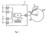
- Fig. 1 is a schematic illustration of an embodiment of a control apparatus for controlling an engine speed indicator in a vehicle in accordance with the method according to the invention.
- the method according to the invention is applicable to any vehicle with internal combustion engine.
- the engine speed indicator in Fig. 1 is an rpm indicator of the type disclosed e.g. in WO 02/092394 and is provided with a pointer 1 that indicates actual engine speed, and a number of light emitting elements, e.g. light emitting diodes (LEDs) 2, lying next to each other along the periphery of the indicator.
- LEDs light emitting diodes
- each LED 2 there are ten LEDs 2 located between 1000 and 1500 rpm, i.e. just along part of the periphery, such that each LED 2 corresponds to an rpm interval of 50 rpm.
- This particular rpm interval is the interval within which e.g. trucks with diesel engines are operated for up to 95 % of the time, i.e. a major part of the time.
- the number of LEDs 2 as well as the rpm interval between which the LEDs 2 are located is chosen with respect to the type of engine, i.e. diesel or petrol, and the desired resolution of the indicator.
- the control apparatus in Fig. 1 comprises a computer 3 with a central processing unit (CPU) 31 that is connected to a computer program product 32 in the form of a storage unit that stores a computer program 33, a table 34, and a memory 35 in which limit values to be described below are set.
- CPU central processing unit
- a computer program product 32 in the form of a storage unit that stores a computer program 33, a table 34, and a memory 35 in which limit values to be described below are set.
- the CPU 31 is connected to four input ports, namely an input port 36 for monitoring actual engine speed, i.e. rpm, appearing on an input terminal 4, an input port 37 for monitoring actual delivered engine power appearing on an input terminal 5, an input port 38 for monitoring actual vehicle speed, i.e. km/h, appearing on an input terminal 6, and an input port 39 for monitoring actual gear ratio appearing on an input terminal 7.
- the CPU 31 is connected to an output port 40 for communication with the engine speed indicator to control the LEDs 2 as will be described below.
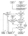
- Fig. 2 is a flow chart illustrating the steps of an embodiment of the method according to the invention of indicating ecological and economical driving by means of the LEDs 2 on the engine speed indicator in Fig. 1 in a vehicle.
- the CPU 31 monitors actual engine speed on input terminal 4 in Step 11, actual delivered engine power on input terminal 5 in Step 12, actual vehicle speed on input terminal 6 in Step 13, and actual gear ratio on input terminal 7 in Step 14.
- Step 15 in response to an actual engine power value on input terminal 5, an engine speed interval that is optimal from ecological and economical point of view is defined in the CPU 31 by means of the table 34 stored in the storage unit 32 in the computer 3.
- the table 34 has been set up to define for a number of engine power values, predetermined engine speed limit values, i.e. upper and lower limit values, that if adhered to by the driver, would enable him to drive as ecological and economical as possible.
- an optimal engine speed interval can equally well be calculated in real time from an actual value of delivered engine power provided that enough computer capacity is available.
- Step 16 the actual engine speed monitored in Step 11 is compared with the optimal engine speed interval defined in Step 15.
- Step 17 it is queried whether the actual engine speed is outside the optimal engine speed interval defined in Step 15.
- Step 18 If the answer is YES to the query in Step 17, i.e. the actual engine speed is outside the optimal engine speed interval defined in Step 15, after a predetermined short period of time, e.g. 5 -10 s set in memory 35, it is queried in Step 18 whether the engine speed is > the highest speed in the optimal interval.
- a time interval of 5 -10 s will allow the driver to be outside the optimal interval for a short period of time in connection with e.g. a gear shift.
- Step 19 If the answer to the query in Step 18 is NO, i.e. the engine speed is not higher than the highest speed in the optimal interval, it is queried in Step 19 whether the vehicle speed as monitored in Step 13 is ⁇ than a predetermined vehicle speed, e.g. a value between 15 - 25 km/h, set in memory 35.
- a predetermined vehicle speed e.g. a value between 15 - 25 km/h
- Abnormal driving mode is in this context defined as a vehicle speed less than a predetermined value, for example a value between 15 - 25 km/h, which in connection with e.g. slow driving, and even standstill, will allow the driver to be outside the optimal interval.
- Normal driving mode is thus here defined as all other vehicle speeds obtainable with the type of vehicle concerned, for example truck with diesel or petrol engine.
- the CPU 31 illuminates a segment, i.e. at least one of the ten LEDs 2 on the engine speed indicator in correspondence to the optimal engine speed interval defined in Step 15 as indicated in Step 20 to alert the driver about the fact that he should adjust the engine speed to be within the optimal engine speed interval illuminated by the LEDs 2 on the engine speed indicator to reduce the emission of unhealthy gases and save fuel since he is not driving ecologically and economically for the time being.
- Step 21 it will then be queried whether LEDs 2 are illuminated.
- Step 21 If the answer to the query in Step 21 is YES, i.e. at least one of the ten LEDs 2 is illuminated, the LED or LEDs 2 in question are switched off in Step 22 after a predetermined period of time, e.g. 5 - 10 s set in memory 35, as a confirmation of that the driver is now driving ecologically and economically.
- a predetermined period of time e.g. 5 - 10 s set in memory 35
- a time interval of 5 - 10 s will be enough for the driver to understand that he should stay with the pointer 1 within the illuminated segment of the LEDs 2.
- the driver is driving at e.g. an engine speed of 1400 rpm as indicated by the pointer 1 and monitored by the CPU 31 via input port 36 and that engine speed is outside the optimal engine speed interval of e.g. 1100 - 1200 rpm as defined in Step 15 at the engine power that is delivered for the moment as monitored by the CPU 31 via input port 37, a segment of the two LEDs 2 corresponding to that interval will be illuminated to alert the driver to lower the engine speed. If he reduces the engine speed such that the pointer 1 is inside the illuminated LED segment on the indicator, i.e. somewhere between 1100 and 1200 rpm, for the predetermined period of time, i.e. 5 - 10 s, the illuminated LED segment in question will be switched off as an indication of that the driver is now driving ecologically and economically.
- Step 21 If the answer to the query in Step 21 is NO, i.e. no segment of the LEDs 2 is illuminated, the LEDs 2 are kept switched off as indicated in Step 23 due to the fact that the driver is already driving ecologically and economically.
- Step 21 is not absolutely necessary but that Steps 22 and 23 can be combined.
- Step 24 If the answer is YES to the query in Step 18, i.e. the engine speed is higher than the highest speed in the optimal interval, it is queried in Step 24 whether the vehicle is in highest gear as monitored by the CPU 31 via input port 39 on input terminal 7 in Step 14.
- Step 24 If the answer is YES to the query in Step 24, i.e. the vehicle is in highest gear, the CPU 31 keeps the LEDs 2 of the engine speed indicator switched off in Step 23.
- the reason for keeping the LEDs 2 switched off is that the vehicle cannot be switched up into a higher gear to lower the engine speed since it is already in highest gear. Thus, the engine power and the fuel consumption can normally not be lower than they already are.
- Step 19 If the answer is NO to the query in Step 24, i.e. the vehicle is not in highest gear, it is queried in Step 19 whether the vehicle speed as monitored in Step 13 is ⁇ than the predetermined vehicle speed, i.e. the speed in the interval of 15 - 25 km/h, set in memory 35.
- the predetermined vehicle speed i.e. the speed in the interval of 15 - 25 km/h
- Step 19 If the answer to the query in Step 19 is YES, i.e. the vehicle speed is ⁇ than the set predetermined vehicle speed corresponding to standstill or a very low vehicle speed, the CPU 31 keeps the LEDs 2 of the engine speed indicator switched off as indicated in Step 23.
Abstract
Description
- The invention relates generally to vehicles and more specifically to a method and a computer program of indicating ecological and economical driving to a driver of a vehicle.
- The emission of different more or less unhealthy gases from an engine in a vehicle is mainly dependent on engine speed and delivered engine power.
- For ecological reasons, it is of importance that vehicles are driven such that the emission of such gases is kept as low as possible.
- Delivered engine power can be calculated with knowledge of e.g. engine torque, and engine torque in its turn can be determined by measuring actual torque in the drive line of the vehicle or with knowledge of the fuel consumption of the engine.
- Engine torque is proportional to the amount of injected diesel in a diesel engine and to the position of the throttle valve in a spark ignition engine.
- Thus, there is a connection between low emission and low fuel consumption which means that an ecological way of driving also is an economical way of driving.
- Through the document
DE 100 14 818 A1 is previously known a device for determining and displaying optimum motor speed or r.p.m. range to a driver of a vehicle. This range is variable and primarily based on calculated optimal, i.e. minimal, fuel consumption at a given power demand, for example as derived from a given gas pedal position. The optimum motor speed range is illuminated on the motor speed indicator through activation of a series of light emitting elements only when the sensed current motor speed is outside the optimum range. The driver is thus continuously alerted when a driving strategy is chosen, which is not optimal regarding fuel consumption. One embodiment entails displaying the optimum range when the current motor speed has been outside the optimum range for a certain time period, for example 1 to 3 seconds. -
DE 10014818 (D1) is considered to represent the closest prior art. D1 describes a method for indicating optimal engine speed regarding fuel consumption, which is considered to correspond to ecological and economical driving, to a driver of a vehicle and solves the problem of alerting a driver to optimized driving regarding said fuel consumption (see paragraph [0010], [0018]-[0021], abstract andfig. 2-4 ). - D1 states that in certain traffic situations, such as city traffic, the driver is not burdened with unnecessary indications by limiting the indications to quasi-stationary conditions of the engine operation (see paragraph [0008] and [0009]). The segment described in D1 may distract the driver in certain situations, such as when the vehicle is driven with low quasi-stationary speed in city traffic with an engine speed outside the optimal interval, reversing the vehicle with quasi-stationary speed with an engine speed outside the optimal interval or when driving slowly with quasi-stationary speed on broken ground, e.g. on construction sites, where the driver may choose a lower gear than the optimal in order to increase the engine speed margin to the engine stall speed. Also, the method of D1 does not illuminate the segment when the driver keeps the engine speed "non-quasi stationary" outside the optimal engine speed interval, e.g. during a typical sporty drive style with large vehicle speed and engine speed variations.
- Solutions like this, which derives demanded engine power from the gas pedal position for calculating an optimum motor speed range, also disclosed in
US4523457 , has a drawback as depending on the pedal position thus not being suitable for use with a cruise control function, for example being present in most trucks of today. - Also, solutions for alerting a driver to optimized driving regarding fuel consumption should take care not to risk compromising traffic safety. A driver's attention could for example be unduly drawn away from certain traffic situations involving an increased risk for accidents, such as driving in city traffic where the vehicle speed is low, queuing or traffic jam situations and the like low speed driving situations if the driver, for example is focused on constantly keeping the motor speed within an optimum range instead of focusing on vehicle surroundings and avoiding incidents. Since, for example, a trucker of today is highly cost conscious the risk exists of him/her trying to keep fuel consumption at a minimum also during such traffic conditions as described, when given the means for it.
- It is, however, difficult for a driver to adjust his driving such that it is optimal from ecological and economical point of view all the time in dependence of the vehicle velocity.
- The object of the invention is to enable a driver of a vehicle to adjust his driving such that it is optimal both from ecological and economical point of view depending on the vehicle speed, thus, in such a manner that the emission values are low at the same time as the fuel consumption is low for a certain vehicle speed range.
- This is attained by a method according to the invention of indicating ecological and economical driving to a driver in a vehicle by monitoring engine speed and engine power, indicating the engine speed on an indicator, defining an optimal engine speed interval from ecological and economical point of view in response to an actual engine power value, comparing the actual engine speed value and the optimal engine speed interval, illuminating a segment of at least one of a number of light emitting elements on the indicator in correspondence to the optimal engine speed interval in case the actual engine speed value is outside the optimal engine speed interval to alert the driver to adjust the engine speed to within the optimal engine speed interval, switching off the illumination of the segment in response to that the actual engine speed value is inside the optimal engine speed interval, and monitoring vehicle speed, and keeping the light emitting elements switched off in response to that the vehicle speed is lower than a predetermined value. Hereby, the driver will receive a clear confirmation of whether or not he is driving at an optimal engine speed during a certain vehicle speed range, i.e. normal driving mode and, no segment will be illuminated at non-optimal driving at low vehicle speeds or standstill, i.e. abnormal driving mode.
- In one embodiment of the invention, the optimal engine speed interval is defined from a predetermined table. This will save computer time and capacity.
- If computer time and capacity is of no problem, the optimal engine speed interval can instead be defined in real time by calculating the interval from an actual engine power value.
- According to one embodiment of the invention, the segment is illuminated in case the actual engine speed value is outside the optimal engine speed interval for a first predetermined period of time. Hereby, the driver will be allowed to be outside the optimal interval for a short period of time without any segment being illuminated.
- In one embodiment, the illumination of the segment is switched off in response to that the actual engine speed value is inside the optimal engine speed interval for a second predetermined period of time. Hereby, the driver will be prompted to maintain the engine speed within the optimal interval.
- Furthermore, gear ratio may be monitored and the light emitting elements on the engine speed indicator are kept switched off in response to that the engine speed is higher than the highest speed in the optimal interval and the vehicle is in highest gear.Hereby, no segment will be illuminated when it is not possible for the driver to make an up-shift to lower the engine speed since he is already driving in highest gear.
- The invention will be described below with reference to the appended drawing on which
-
Fig. 1 is a schematic illustration of an embodiment of an apparatus for controlling an engine speed indicator in accordance with the method according to the invention, and -
Fig. 2 is a flow chart illustrating the steps of an embodiment of the method according to the invention of indicating ecological and economical driving to a driver in a vehicle. -
Fig. 1 is a schematic illustration of an embodiment of a control apparatus for controlling an engine speed indicator in a vehicle in accordance with the method according to the invention. - The method according to the invention is applicable to any vehicle with internal combustion engine.
- The engine speed indicator in
Fig. 1 is an rpm indicator of the type disclosed e.g. inWO 02/092394 pointer 1 that indicates actual engine speed, and a number of light emitting elements, e.g. light emitting diodes (LEDs) 2, lying next to each other along the periphery of the indicator. - In the embodiment in
Fig. 1 , there are tenLEDs 2 located between 1000 and 1500 rpm, i.e. just along part of the periphery, such that eachLED 2 corresponds to an rpm interval of 50 rpm. - This particular rpm interval is the interval within which e.g. trucks with diesel engines are operated for up to 95 % of the time, i.e. a major part of the time.
- The number of
LEDs 2 as well as the rpm interval between which theLEDs 2 are located is chosen with respect to the type of engine, i.e. diesel or petrol, and the desired resolution of the indicator. - The control apparatus in
Fig. 1 comprises acomputer 3 with a central processing unit (CPU) 31 that is connected to acomputer program product 32 in the form of a storage unit that stores acomputer program 33, a table 34, and amemory 35 in which limit values to be described below are set. - The
CPU 31 is connected to four input ports, namely aninput port 36 for monitoring actual engine speed, i.e. rpm, appearing on an input terminal 4, aninput port 37 for monitoring actual delivered engine power appearing on aninput terminal 5, an input port 38 for monitoring actual vehicle speed, i.e. km/h, appearing on an input terminal 6, and aninput port 39 for monitoring actual gear ratio appearing on an input terminal 7. - The
CPU 31 is connected to anoutput port 40 for communication with the engine speed indicator to control theLEDs 2 as will be described below. -
Fig. 2 is a flow chart illustrating the steps of an embodiment of the method according to the invention of indicating ecological and economical driving by means of theLEDs 2 on the engine speed indicator inFig. 1 in a vehicle. - In accordance with the invention, the
CPU 31 monitors actual engine speed on input terminal 4 inStep 11, actual delivered engine power oninput terminal 5 inStep 12, actual vehicle speed on input terminal 6 inStep 13, and actual gear ratio on input terminal 7 inStep 14. - In
Step 15, in response to an actual engine power value oninput terminal 5, an engine speed interval that is optimal from ecological and economical point of view is defined in theCPU 31 by means of the table 34 stored in thestorage unit 32 in thecomputer 3. - The table 34 has been set up to define for a number of engine power values, predetermined engine speed limit values, i.e. upper and lower limit values, that if adhered to by the driver, would enable him to drive as ecological and economical as possible.
- It is to be understood that instead of having a pre-calculated table, an optimal engine speed interval can equally well be calculated in real time from an actual value of delivered engine power provided that enough computer capacity is available.
- In
Step 16 the actual engine speed monitored inStep 11 is compared with the optimal engine speed interval defined inStep 15. - In
Step 17, it is queried whether the actual engine speed is outside the optimal engine speed interval defined inStep 15. - If the answer is YES to the query in
Step 17, i.e. the actual engine speed is outside the optimal engine speed interval defined inStep 15, after a predetermined short period of time, e.g. 5 -10 s set inmemory 35, it is queried inStep 18 whether the engine speed is > the highest speed in the optimal interval. - A time interval of 5 -10 s will allow the driver to be outside the optimal interval for a short period of time in connection with e.g. a gear shift.
- If the answer to the query in
Step 18 is NO, i.e. the engine speed is not higher than the highest speed in the optimal interval, it is queried inStep 19 whether the vehicle speed as monitored inStep 13 is < than a predetermined vehicle speed, e.g. a value between 15 - 25 km/h, set inmemory 35. - Abnormal driving mode is in this context defined as a vehicle speed less than a predetermined value, for example a value between 15 - 25 km/h, which in connection with e.g. slow driving, and even standstill, will allow the driver to be outside the optimal interval. Normal driving mode is thus here defined as all other vehicle speeds obtainable with the type of vehicle concerned, for example truck with diesel or petrol engine.
- If the answer to the query in
Step 19 is NO, i.e. the vehicle speed is > than the set predetermined vehicle speed, theCPU 31 illuminates a segment, i.e. at least one of the tenLEDs 2 on the engine speed indicator in correspondence to the optimal engine speed interval defined inStep 15 as indicated inStep 20 to alert the driver about the fact that he should adjust the engine speed to be within the optimal engine speed interval illuminated by theLEDs 2 on the engine speed indicator to reduce the emission of unhealthy gases and save fuel since he is not driving ecologically and economically for the time being. - Any adjustment of the engine speed by the driver will be noticed by the
CPU 31 monitoring input terminal 4 in asuccessive Step 11. Should the driver adjust the engine speed to be within the optimal engine speed interval illuminated by theLEDs 2 on the engine speed indicator, the answer to a successive query inStep 17 will be NO. - In
Step 21 it will then be queried whetherLEDs 2 are illuminated. - If the answer to the query in
Step 21 is YES, i.e. at least one of the tenLEDs 2 is illuminated, the LED orLEDs 2 in question are switched off inStep 22 after a predetermined period of time, e.g. 5 - 10 s set inmemory 35, as a confirmation of that the driver is now driving ecologically and economically. - A time interval of 5-10 s will be enough for the driver to understand that he should stay with the
pointer 1 within the illuminated segment of theLEDs 2. - As an example, if the driver is driving at e.g. an engine speed of 1400 rpm as indicated by the
pointer 1 and monitored by theCPU 31 viainput port 36 and that engine speed is outside the optimal engine speed interval of e.g. 1100 - 1200 rpm as defined inStep 15 at the engine power that is delivered for the moment as monitored by theCPU 31 viainput port 37, a segment of the twoLEDs 2 corresponding to that interval will be illuminated to alert the driver to lower the engine speed. If he reduces the engine speed such that thepointer 1 is inside the illuminated LED segment on the indicator, i.e. somewhere between 1100 and 1200 rpm, for the predetermined period of time, i.e. 5 - 10 s, the illuminated LED segment in question will be switched off as an indication of that the driver is now driving ecologically and economically. - If the answer to the query in
Step 21 is NO, i.e. no segment of theLEDs 2 is illuminated, theLEDs 2 are kept switched off as indicated inStep 23 due to the fact that the driver is already driving ecologically and economically. - It is to be understood that
Step 21 is not absolutely necessary but that Steps 22 and 23 can be combined. - If the answer is YES to the query in
Step 18, i.e. the engine speed is higher than the highest speed in the optimal interval, it is queried inStep 24 whether the vehicle is in highest gear as monitored by theCPU 31 viainput port 39 on input terminal 7 inStep 14. - If the answer is YES to the query in
Step 24, i.e. the vehicle is in highest gear, theCPU 31 keeps theLEDs 2 of the engine speed indicator switched off inStep 23. - The reason for keeping the
LEDs 2 switched off is that the vehicle cannot be switched up into a higher gear to lower the engine speed since it is already in highest gear. Thus, the engine power and the fuel consumption can normally not be lower than they already are. - If the answer is NO to the query in
Step 24, i.e. the vehicle is not in highest gear, it is queried inStep 19 whether the vehicle speed as monitored inStep 13 is < than the predetermined vehicle speed, i.e. the speed in the interval of 15 - 25 km/h, set inmemory 35. - If the answer to the query in
Step 19 is YES, i.e. the vehicle speed is < than the set predetermined vehicle speed corresponding to standstill or a very low vehicle speed, theCPU 31 keeps theLEDs 2 of the engine speed indicator switched off as indicated inStep 23. - As should be apparent from the above, by illuminating an optimal segment on the engine speed indicator to draw the driver's attention to the fact that he is not driving ecological and economical for the time being but should adjust his engine speed to be within the illuminated segment, switching off the illumination when the engine speed is within the illuminated segment and keeping it switched off when driving at low speed, in the end the driver will attempt to drive so ecological and economical that no segment will be illuminated during so called normal driving mode only, the driver not being displayed an optimal segment during so called abnormal or low speed driving mode when driving non-optimal in an ecological and economical point of view. Thus, an alerting function for ecological and economical driving is provided, which limits the risk of drawing the driver's attention away from the vehicle surroundings and fellow road-users at traffic situations involving enhanced risk for incidents and accidents.
Claims (9)
- A method of indicating ecological and economical driving to a driver of a vehicle, comprising the steps of monitoring engine speed and engine power, and indicating the engine speed on an indicator, characterized by the steps of- defining an optimal engine speed interval from ecological and economical point of view in response to an actual engine power value,- comparing the actual engine speed value and the optimal engine speed interval,- illuminating a segment of at least one of a number of light emitting elements on the indicator in correspondence to the optimal engine speed interval in case the actual engine speed value is outside the optimal engine speed interval to alert the driver to adjust the engine speed to within the optimal engine speed interval,- switching off the illumination of the segment in response to that the actual engine speed value is inside the optimal engine speed interval, and- monitoring vehicle speed, and keeping the light emitting elements switched off in response to that the vehicle speed is lower than a predetermined value.
- The method according to claim 1, characterized by the step of defining the optimal engine speed interval from a predetermined table.
- The method according to claim 1, characterized by the step of defining the optimal engine speed interval in real time by calculating the interval from an actual engine power value.
- The method according to claim 1, characterized by the step of illuminating the segment in case the actual engine speed value is outside the optimal engine speed interval for a first predetermined period of time.
- The method according to claim 1, characterized by the step of switching off the illumination of the segment in response to that the actual engine speed value is inside the optimal engine speed interval for a second predetermined period of time.
- The method according to claim 1, characterized by the step of monitoring gear ratio, and keeping the light emitting elements switched off in response to that the engine speed is higher than the highest speed in the optimal interval and the vehicle is in highest gear.
- The method according to claim 1, characterized by keeping the light emitting elements switched off in response to that the vehicle speed is lower than a value between 15 to 25 km/h.
- A computer program (33) comprising code means that when executed on a computer causes the computer to carry out all steps of one of claim 1 to claim 7.
- A computer program product (32) comprising a computer program according to claim 8 and a computer readable medium on which the computer program is stored.
Applications Claiming Priority (2)
| Application Number | Priority Date | Filing Date | Title |
|---|---|---|---|
| SE0400482A SE527523C2 (en) | 2004-02-26 | 2004-02-26 | Indication of ecological and economic driving of a vehicle |
| PCT/SE2005/000268 WO2005082674A1 (en) | 2004-02-26 | 2005-02-24 | Indicating ecological and economical driving of a vehicle |
Publications (2)
| Publication Number | Publication Date |
|---|---|
| EP1718499A1 EP1718499A1 (en) | 2006-11-08 |
| EP1718499B1 true EP1718499B1 (en) | 2008-08-20 |
Family
ID=32067264
Family Applications (1)
| Application Number | Title | Priority Date | Filing Date |
|---|---|---|---|
| EP05711128A Not-in-force EP1718499B1 (en) | 2004-02-26 | 2005-02-24 | Indicating ecological and economical driving of a vehicle |
Country Status (5)
| Country | Link |
|---|---|
| EP (1) | EP1718499B1 (en) |
| AT (1) | ATE405457T1 (en) |
| DE (1) | DE602005009145D1 (en) |
| SE (1) | SE527523C2 (en) |
| WO (1) | WO2005082674A1 (en) |
Cited By (1)
| Publication number | Priority date | Publication date | Assignee | Title |
|---|---|---|---|---|
| DE102009049367A1 (en) * | 2009-10-14 | 2011-04-21 | GM Global Technology Operations, Inc., Detroit | Method for graphical visualizing current driving conditions of motor vehicle, involves forming algorithm from sum of proportion that is proportional to accelerator pedal position and another proportion that depends on one of engine speed |
Families Citing this family (7)
| Publication number | Priority date | Publication date | Assignee | Title |
|---|---|---|---|---|
| JP4311451B2 (en) | 2007-01-16 | 2009-08-12 | トヨタ自動車株式会社 | Vehicle and control method thereof |
| FR2911657B1 (en) * | 2007-01-24 | 2009-02-20 | Renault Sas | METHOD AND DEVICE FOR ASSISTING THE DRIVING OF A VEHICLE. |
| FR2922643B1 (en) * | 2007-10-23 | 2010-01-29 | Peugeot Citroen Automobiles Sa | METHOD FOR SIMULATION OF LIFTING A VIRTUAL CREATURE ASSOCIATED WITH A MOTOR VEHICLE |
| GB2457916B (en) | 2008-02-28 | 2010-01-06 | Tom Tinsley | A portable driving aid |
| DE102008028449A1 (en) * | 2008-06-14 | 2009-12-17 | Bayerische Motoren Werke Aktiengesellschaft | motor vehicle |
| GB2467323A (en) * | 2009-01-29 | 2010-08-04 | Nicholas Anderson | Engine speed monitor |
| SE534642C2 (en) | 2010-02-10 | 2011-11-01 | Vdii Innovation Ab | Method and apparatus for assessing deceleration of a vehicle |
Family Cites Families (5)
| Publication number | Priority date | Publication date | Assignee | Title |
|---|---|---|---|---|
| SE411325B (en) * | 1978-05-12 | 1979-12-17 | Saab Scania Ab | ARRANGEMENTS FOR INFORMING IN VEHICLES ABOUT ENGINE SPEED AND ENGINE LOAD |
| DE3229065C2 (en) * | 1982-08-04 | 1984-09-27 | Daimler-Benz Ag, 7000 Stuttgart | Tachometer with economy field |
| DE3912359A1 (en) * | 1989-04-14 | 1990-10-25 | Man Nutzfahrzeuge Ag | Gear-change aid for motor vehicle driver - uses electronic processing to computer gear-change positions with indication on dashboard instruments |
| DE10014818B4 (en) * | 2000-03-27 | 2004-04-15 | Daimlerchrysler Ag | Device for determining and displaying an optimal speed range |
| SE519083C2 (en) * | 2001-05-17 | 2003-01-07 | Scania Cv Ab | Speedometer for a vehicle |
-
2004
- 2004-02-26 SE SE0400482A patent/SE527523C2/en not_active IP Right Cessation
-
2005
- 2005-02-24 EP EP05711128A patent/EP1718499B1/en not_active Not-in-force
- 2005-02-24 DE DE602005009145T patent/DE602005009145D1/en active Active
- 2005-02-24 WO PCT/SE2005/000268 patent/WO2005082674A1/en active Application Filing
- 2005-02-24 AT AT05711128T patent/ATE405457T1/en not_active IP Right Cessation
Cited By (1)
| Publication number | Priority date | Publication date | Assignee | Title |
|---|---|---|---|---|
| DE102009049367A1 (en) * | 2009-10-14 | 2011-04-21 | GM Global Technology Operations, Inc., Detroit | Method for graphical visualizing current driving conditions of motor vehicle, involves forming algorithm from sum of proportion that is proportional to accelerator pedal position and another proportion that depends on one of engine speed |
Also Published As
| Publication number | Publication date |
|---|---|
| ATE405457T1 (en) | 2008-09-15 |
| SE527523C2 (en) | 2006-03-28 |
| WO2005082674A1 (en) | 2005-09-09 |
| SE0400482D0 (en) | 2004-02-26 |
| EP1718499A1 (en) | 2006-11-08 |
| DE602005009145D1 (en) | 2008-10-02 |
| SE0400482L (en) | 2005-08-27 |
Similar Documents
| Publication | Publication Date | Title |
|---|---|---|
| EP1718499B1 (en) | Indicating ecological and economical driving of a vehicle | |
| US8037870B2 (en) | Fuel economy improvement assist device and method of fuel economy improvement assist | |
| EP1386776B1 (en) | Evaluation system for vehicle operating conditions | |
| JP4539638B2 (en) | Accelerator position display device | |
| US20140167944A1 (en) | Display device | |
| CN102358189A (en) | Accelerator level display device | |
| EP2728149B1 (en) | Vehicle operation assist apparatus | |
| US9079588B2 (en) | Method and device for outputting driving information indicating an acceleration option that is optimal in terms of power consumption in a motor vehicle | |
| JP5040366B2 (en) | Vehicle control device | |
| KR101127443B1 (en) | Induction apparatus for eco driving | |
| JP3180632B2 (en) | Multiplex display for automobile | |
| US7123135B2 (en) | Display control device for vehicle | |
| US20060276950A1 (en) | Motor vehicle | |
| JP4415995B2 (en) | Fuel-saving driving recommendation device | |
| JP3104583B2 (en) | Multiplex display for automobile | |
| JPS637865Y2 (en) | ||
| KR101814149B1 (en) | Apparatus for leading an economic instructions using the fuel efficiency characteristics of the engine | |
| JP4456630B2 (en) | Eco operation status display device | |
| JPS61122035A (en) | Auto cruising aiding monitor | |
| JP7375520B2 (en) | Idling stop vehicle notification device | |
| KR200225991Y1 (en) | A fuel saving system display guide device of a car meter | |
| JP2008290630A (en) | Accelerator pedal reaction control device | |
| JP3510390B2 (en) | Automotive multiple display | |
| WO1999045399A1 (en) | A motor vehicle tachometer | |
| JP2005214086A (en) | Eco-friendly power drive device |
Legal Events
| Date | Code | Title | Description |
|---|---|---|---|
| PUAI | Public reference made under article 153(3) epc to a published international application that has entered the european phase |
Free format text: ORIGINAL CODE: 0009012 |
|
| 17P | Request for examination filed |
Effective date: 20060706 |
|
| AK | Designated contracting states |
Kind code of ref document: A1 Designated state(s): AT BE BG CH CY CZ DE DK EE ES FI FR GB GR HU IE IS IT LI LT LU MC NL PL PT RO SE SI SK TR |
|
| DAX | Request for extension of the european patent (deleted) | ||
| GRAP | Despatch of communication of intention to grant a patent |
Free format text: ORIGINAL CODE: EPIDOSNIGR1 |
|
| GRAJ | Information related to disapproval of communication of intention to grant by the applicant or resumption of examination proceedings by the epo deleted |
Free format text: ORIGINAL CODE: EPIDOSDIGR1 |
|
| GRAP | Despatch of communication of intention to grant a patent |
Free format text: ORIGINAL CODE: EPIDOSNIGR1 |
|
| GRAS | Grant fee paid |
Free format text: ORIGINAL CODE: EPIDOSNIGR3 |
|
| GRAA | (expected) grant |
Free format text: ORIGINAL CODE: 0009210 |
|
| AK | Designated contracting states |
Kind code of ref document: B1 Designated state(s): AT BE BG CH CY CZ DE DK EE ES FI FR GB GR HU IE IS IT LI LT LU MC NL PL PT RO SE SI SK TR |
|
| REG | Reference to a national code |
Ref country code: GB Ref legal event code: FG4D |
|
| REG | Reference to a national code |
Ref country code: CH Ref legal event code: EP |
|
| REG | Reference to a national code |
Ref country code: IE Ref legal event code: FG4D |
|
| REF | Corresponds to: |
Ref document number: 602005009145 Country of ref document: DE Date of ref document: 20081002 Kind code of ref document: P |
|
| PG25 | Lapsed in a contracting state [announced via postgrant information from national office to epo] |
Ref country code: LT Free format text: LAPSE BECAUSE OF FAILURE TO SUBMIT A TRANSLATION OF THE DESCRIPTION OR TO PAY THE FEE WITHIN THE PRESCRIBED TIME-LIMIT Effective date: 20080820 Ref country code: IS Free format text: LAPSE BECAUSE OF FAILURE TO SUBMIT A TRANSLATION OF THE DESCRIPTION OR TO PAY THE FEE WITHIN THE PRESCRIBED TIME-LIMIT Effective date: 20081220 Ref country code: NL Free format text: LAPSE BECAUSE OF FAILURE TO SUBMIT A TRANSLATION OF THE DESCRIPTION OR TO PAY THE FEE WITHIN THE PRESCRIBED TIME-LIMIT Effective date: 20080820 |
|
| PG25 | Lapsed in a contracting state [announced via postgrant information from national office to epo] |
Ref country code: SI Free format text: LAPSE BECAUSE OF FAILURE TO SUBMIT A TRANSLATION OF THE DESCRIPTION OR TO PAY THE FEE WITHIN THE PRESCRIBED TIME-LIMIT Effective date: 20080820 Ref country code: AT Free format text: LAPSE BECAUSE OF FAILURE TO SUBMIT A TRANSLATION OF THE DESCRIPTION OR TO PAY THE FEE WITHIN THE PRESCRIBED TIME-LIMIT Effective date: 20080820 Ref country code: ES Free format text: LAPSE BECAUSE OF FAILURE TO SUBMIT A TRANSLATION OF THE DESCRIPTION OR TO PAY THE FEE WITHIN THE PRESCRIBED TIME-LIMIT Effective date: 20081201 Ref country code: FI Free format text: LAPSE BECAUSE OF FAILURE TO SUBMIT A TRANSLATION OF THE DESCRIPTION OR TO PAY THE FEE WITHIN THE PRESCRIBED TIME-LIMIT Effective date: 20080820 |
|
| PG25 | Lapsed in a contracting state [announced via postgrant information from national office to epo] |
Ref country code: BE Free format text: LAPSE BECAUSE OF FAILURE TO SUBMIT A TRANSLATION OF THE DESCRIPTION OR TO PAY THE FEE WITHIN THE PRESCRIBED TIME-LIMIT Effective date: 20080820 |
|
| PG25 | Lapsed in a contracting state [announced via postgrant information from national office to epo] |
Ref country code: BG Free format text: LAPSE BECAUSE OF FAILURE TO SUBMIT A TRANSLATION OF THE DESCRIPTION OR TO PAY THE FEE WITHIN THE PRESCRIBED TIME-LIMIT Effective date: 20081120 Ref country code: DK Free format text: LAPSE BECAUSE OF FAILURE TO SUBMIT A TRANSLATION OF THE DESCRIPTION OR TO PAY THE FEE WITHIN THE PRESCRIBED TIME-LIMIT Effective date: 20080820 |
|
| PG25 | Lapsed in a contracting state [announced via postgrant information from national office to epo] |
Ref country code: PT Free format text: LAPSE BECAUSE OF FAILURE TO SUBMIT A TRANSLATION OF THE DESCRIPTION OR TO PAY THE FEE WITHIN THE PRESCRIBED TIME-LIMIT Effective date: 20090120 Ref country code: CZ Free format text: LAPSE BECAUSE OF FAILURE TO SUBMIT A TRANSLATION OF THE DESCRIPTION OR TO PAY THE FEE WITHIN THE PRESCRIBED TIME-LIMIT Effective date: 20080820 Ref country code: SK Free format text: LAPSE BECAUSE OF FAILURE TO SUBMIT A TRANSLATION OF THE DESCRIPTION OR TO PAY THE FEE WITHIN THE PRESCRIBED TIME-LIMIT Effective date: 20080820 Ref country code: RO Free format text: LAPSE BECAUSE OF FAILURE TO SUBMIT A TRANSLATION OF THE DESCRIPTION OR TO PAY THE FEE WITHIN THE PRESCRIBED TIME-LIMIT Effective date: 20080820 |
|
| PLBE | No opposition filed within time limit |
Free format text: ORIGINAL CODE: 0009261 |
|
| STAA | Information on the status of an ep patent application or granted ep patent |
Free format text: STATUS: NO OPPOSITION FILED WITHIN TIME LIMIT |
|
| 26N | No opposition filed |
Effective date: 20090525 |
|
| PG25 | Lapsed in a contracting state [announced via postgrant information from national office to epo] |
Ref country code: EE Free format text: LAPSE BECAUSE OF FAILURE TO SUBMIT A TRANSLATION OF THE DESCRIPTION OR TO PAY THE FEE WITHIN THE PRESCRIBED TIME-LIMIT Effective date: 20080820 |
|
| PG25 | Lapsed in a contracting state [announced via postgrant information from national office to epo] |
Ref country code: MC Free format text: LAPSE BECAUSE OF NON-PAYMENT OF DUE FEES Effective date: 20090228 |
|
| REG | Reference to a national code |
Ref country code: CH Ref legal event code: PL |
|
| GBPC | Gb: european patent ceased through non-payment of renewal fee |
Effective date: 20090224 |
|
| PG25 | Lapsed in a contracting state [announced via postgrant information from national office to epo] |
Ref country code: LI Free format text: LAPSE BECAUSE OF NON-PAYMENT OF DUE FEES Effective date: 20090228 Ref country code: CH Free format text: LAPSE BECAUSE OF NON-PAYMENT OF DUE FEES Effective date: 20090228 |
|
| REG | Reference to a national code |
Ref country code: IE Ref legal event code: MM4A |
|
| PG25 | Lapsed in a contracting state [announced via postgrant information from national office to epo] |
Ref country code: SE Free format text: LAPSE BECAUSE OF FAILURE TO SUBMIT A TRANSLATION OF THE DESCRIPTION OR TO PAY THE FEE WITHIN THE PRESCRIBED TIME-LIMIT Effective date: 20081120 Ref country code: IE Free format text: LAPSE BECAUSE OF NON-PAYMENT OF DUE FEES Effective date: 20090224 |
|
| PG25 | Lapsed in a contracting state [announced via postgrant information from national office to epo] |
Ref country code: GB Free format text: LAPSE BECAUSE OF NON-PAYMENT OF DUE FEES Effective date: 20090224 |
|
| PG25 | Lapsed in a contracting state [announced via postgrant information from national office to epo] |
Ref country code: PL Free format text: LAPSE BECAUSE OF FAILURE TO SUBMIT A TRANSLATION OF THE DESCRIPTION OR TO PAY THE FEE WITHIN THE PRESCRIBED TIME-LIMIT Effective date: 20080820 |
|
| PG25 | Lapsed in a contracting state [announced via postgrant information from national office to epo] |
Ref country code: GR Free format text: LAPSE BECAUSE OF FAILURE TO SUBMIT A TRANSLATION OF THE DESCRIPTION OR TO PAY THE FEE WITHIN THE PRESCRIBED TIME-LIMIT Effective date: 20081121 |
|
| PG25 | Lapsed in a contracting state [announced via postgrant information from national office to epo] |
Ref country code: LU Free format text: LAPSE BECAUSE OF NON-PAYMENT OF DUE FEES Effective date: 20090224 |
|
| PG25 | Lapsed in a contracting state [announced via postgrant information from national office to epo] |
Ref country code: HU Free format text: LAPSE BECAUSE OF FAILURE TO SUBMIT A TRANSLATION OF THE DESCRIPTION OR TO PAY THE FEE WITHIN THE PRESCRIBED TIME-LIMIT Effective date: 20090221 |
|
| PG25 | Lapsed in a contracting state [announced via postgrant information from national office to epo] |
Ref country code: TR Free format text: LAPSE BECAUSE OF FAILURE TO SUBMIT A TRANSLATION OF THE DESCRIPTION OR TO PAY THE FEE WITHIN THE PRESCRIBED TIME-LIMIT Effective date: 20080820 |
|
| PG25 | Lapsed in a contracting state [announced via postgrant information from national office to epo] |
Ref country code: CY Free format text: LAPSE BECAUSE OF FAILURE TO SUBMIT A TRANSLATION OF THE DESCRIPTION OR TO PAY THE FEE WITHIN THE PRESCRIBED TIME-LIMIT Effective date: 20080820 |
|
| REG | Reference to a national code |
Ref country code: FR Ref legal event code: PLFP Year of fee payment: 11 |
|
| PGFP | Annual fee paid to national office [announced via postgrant information from national office to epo] |
Ref country code: IT Payment date: 20150216 Year of fee payment: 11 |
|
| PGFP | Annual fee paid to national office [announced via postgrant information from national office to epo] |
Ref country code: FR Payment date: 20150210 Year of fee payment: 11 |
|
| REG | Reference to a national code |
Ref country code: FR Ref legal event code: ST Effective date: 20161028 |
|
| PG25 | Lapsed in a contracting state [announced via postgrant information from national office to epo] |
Ref country code: IT Free format text: LAPSE BECAUSE OF NON-PAYMENT OF DUE FEES Effective date: 20160224 |
|
| PG25 | Lapsed in a contracting state [announced via postgrant information from national office to epo] |
Ref country code: FR Free format text: LAPSE BECAUSE OF NON-PAYMENT OF DUE FEES Effective date: 20160229 |
|
| PGFP | Annual fee paid to national office [announced via postgrant information from national office to epo] |
Ref country code: DE Payment date: 20211230 Year of fee payment: 18 |
|
| REG | Reference to a national code |
Ref country code: DE Ref legal event code: R119 Ref document number: 602005009145 Country of ref document: DE |
|
| PG25 | Lapsed in a contracting state [announced via postgrant information from national office to epo] |
Ref country code: DE Free format text: LAPSE BECAUSE OF NON-PAYMENT OF DUE FEES Effective date: 20230901 |