EP1717353A1 - Alkaline galvanizing bath comprising a filtration membrane - Google Patents
Alkaline galvanizing bath comprising a filtration membrane Download PDFInfo
- Publication number
- EP1717353A1 EP1717353A1 EP05009127A EP05009127A EP1717353A1 EP 1717353 A1 EP1717353 A1 EP 1717353A1 EP 05009127 A EP05009127 A EP 05009127A EP 05009127 A EP05009127 A EP 05009127A EP 1717353 A1 EP1717353 A1 EP 1717353A1
- Authority
- EP
- European Patent Office
- Prior art keywords
- filtration membrane
- bath
- electroplating bath
- anode
- cathode
- Prior art date
- Legal status (The legal status is an assumption and is not a legal conclusion. Google has not performed a legal analysis and makes no representation as to the accuracy of the status listed.)
- Granted
Links
Images
Classifications
-
- C—CHEMISTRY; METALLURGY
- C25—ELECTROLYTIC OR ELECTROPHORETIC PROCESSES; APPARATUS THEREFOR
- C25D—PROCESSES FOR THE ELECTROLYTIC OR ELECTROPHORETIC PRODUCTION OF COATINGS; ELECTROFORMING; APPARATUS THEREFOR
- C25D3/00—Electroplating: Baths therefor
- C25D3/02—Electroplating: Baths therefor from solutions
- C25D3/56—Electroplating: Baths therefor from solutions of alloys
- C25D3/565—Electroplating: Baths therefor from solutions of alloys containing more than 50% by weight of zinc
-
- C—CHEMISTRY; METALLURGY
- C25—ELECTROLYTIC OR ELECTROPHORETIC PROCESSES; APPARATUS THEREFOR
- C25D—PROCESSES FOR THE ELECTROLYTIC OR ELECTROPHORETIC PRODUCTION OF COATINGS; ELECTROFORMING; APPARATUS THEREFOR
- C25D17/00—Constructional parts, or assemblies thereof, of cells for electrolytic coating
- C25D17/02—Tanks; Installations therefor
-
- C—CHEMISTRY; METALLURGY
- C25—ELECTROLYTIC OR ELECTROPHORETIC PROCESSES; APPARATUS THEREFOR
- C25D—PROCESSES FOR THE ELECTROLYTIC OR ELECTROPHORETIC PRODUCTION OF COATINGS; ELECTROFORMING; APPARATUS THEREFOR
- C25D17/00—Constructional parts, or assemblies thereof, of cells for electrolytic coating
- C25D17/002—Cell separation, e.g. membranes, diaphragms
-
- C—CHEMISTRY; METALLURGY
- C25—ELECTROLYTIC OR ELECTROPHORETIC PROCESSES; APPARATUS THEREFOR
- C25D—PROCESSES FOR THE ELECTROLYTIC OR ELECTROPHORETIC PRODUCTION OF COATINGS; ELECTROFORMING; APPARATUS THEREFOR
- C25D21/00—Processes for servicing or operating cells for electrolytic coating
- C25D21/06—Filtering particles other than ions
-
- C—CHEMISTRY; METALLURGY
- C25—ELECTROLYTIC OR ELECTROPHORETIC PROCESSES; APPARATUS THEREFOR
- C25D—PROCESSES FOR THE ELECTROLYTIC OR ELECTROPHORETIC PRODUCTION OF COATINGS; ELECTROFORMING; APPARATUS THEREFOR
- C25D21/00—Processes for servicing or operating cells for electrolytic coating
- C25D21/16—Regeneration of process solutions
- C25D21/22—Regeneration of process solutions by ion-exchange
Definitions
- the invention relates to an alkaline electroplating bath for applying zinc alloys to substrates, in which the anode space and the cathode space are separated from one another by a filtration membrane.
- zinc alloys can be deposited on substrates in a consistently high quality.
- the electroplating bath is operated with zinc alloy baths containing organic additives such as brighteners and wetting agents and complexing agents in addition to soluble zinc salts and optionally other metal salts selected from iron, nickel, cobalt and tin salts.
- Bath dilution reduces the concentration of impurities in proportion to the degree of dilution.
- a dilution is easy to carry out, but has the disadvantage that the amount of electrolyte removed from the bath has to be supplied to cost-intensive disposal.
- a complete new approach of the bath can be considered in this context as a special case of Badver Mednung.
- Activated carbon treatment by stirring 0.5-2 g / l of activated carbon into the bath followed by filtration reduces the concentration of impurities by adsorption on the coal. Disadvantage of this method is that it is laborious is and causes only a relatively small reduction.
- Alkaline Zn baths contain a factor of 5 to 10 lower proportion of organic additives as acidic baths. Accordingly, contamination by decomposition products is generally less critical. In the case of alkaline alloy baths, however, the addition of significant amounts of organic complexing agents is required to complex the alloying additive (Fe, Co, Ni, Sn). These are oxidatively degraded at the anode and the accumulated decomposition products have a negative effect on the production process.
- the EP 1 369 505 A2 discloses a method for purifying a zinc-nickel electrolyte in a galvanic process in which a portion of the process bath used in the process is evaporated until phase separation into a lower phase, at least one middle phase and an upper phase occurs, and the lower one and the upper phase are separated. This process requires several stages and is disadvantageous in terms of its energy requirements from a cost point of view.
- the WO 00/06807 and WO 01/96631 describe electroplating baths for applying zinc-nickel coatings. To avoid the undesirable decomposition of additives at the anode, it is proposed to separate the anode from the alkaline electrolyte through an ion exchange membrane.
- the baths known in the prior art have the disadvantage that in the anodic decomposition of the nitrogen-containing complexing agent cyanide is formed and accumulates in non-negligible concentration.
- the invention has for its object to provide an alkaline electroplating bath, which does not have the aforementioned disadvantages.
- the life of the bath is to be increased, the anodic decomposition of organic constituents of the bath to be minimized and, when it is used, a layer thickness of consistently high quality to be obtained on the coated substrate.
- the invention relates to an alkaline electroplating bath for applying zinc alloys on substrates having a cathode and an anode, which has a filtration membrane which separates the anode space and the cathode space of the bath from each other.
- filtration membranes are used.
- the size of the pores of these filtration membranes is generally in a range from 0.0001 to 1.0 ⁇ m and from 0.001 to 1.0 ⁇ m, depending on the type of membrane (nano- or ultrafiltration membrane).
- the pore size is in a range of 0.1 to 0.3 microns.
- the filtration membrane contained in the alkaline electroplating bath according to the invention may consist of various organic or inorganic, alkali-resistant materials. These materials are, for example, ceramics, polytetrafluoroethylene (PTFE), polysulfones and polypropylene.
- PTFE polytetrafluoroethylene
- polysulfones polysulfones
- polypropylene polypropylene
- filtration membranes made of polypropylene.
- the filtration membrane in the alkaline electroplating bath according to the invention is designed as a flat membrane.
- the alkaline electroplating bath according to the invention can also be realized with other membrane forms, examples being hoses, capillaries and hollow fibers.
- Such baths are for example in US 5,417,840 .
- US 4,421,611 US 4,877,496 or US 6,652,728 described.
- the alkaline electroplating bath according to the invention has the advantage that in it also baths for the deposition of zinc alloys can be used, which are suitable for use in the from WO 00/06807 and WO 01/96631 known alkaline zinc-nickel bath with an ion exchange membrane are not suitable.
- sold by the applicant bath "Protedur Ni-75" to call which is characterized by a particularly high efficiency.
- the previously used anodes can be used further. These are mostly nickel anodes.
- the use of these anodes is less expensive than that from the WO 00/06807 known electroplating bath, in which special platinum-plated titanium anodes must be used in addition.
- the anode space is preferably made smaller than the cathode space, since the essential processes take place there.
- Both baths were operated with and without filtration membrane in 5-liter tanks.
- the filtration membrane used was the Abwa-Tec polymer membrane P150F, which has a pore size of 0.12 ⁇ m.
- the membrane was placed in the anode to cathode bath with the anolyte and catholyte being identical, ie, no special anolyte was added.
- iron sheets (7 ⁇ 10 cm), which are usually used for Hull cell tests, were used as workpieces to be coated and coated at a current density of 2 A / dm 2 .
- the baths were operated in serial connection. The movement of the iron sheets was mechanical, at a speed of 1.4 m / min.
- Table 2 shows the Hull cell layer thickness in a new approach and old approach depending on the throughput with and without filtration membrane. The layer thickness measurements were made after adjustment of the baths.
- the dots lie on the Hullzellenblechen 3 cm from the bottom and 2.5 cm from the left and right lateral edge. On the left side is the high current density (point A) and on the right the low current density (point B).
- the average layer thickness is about 35% higher in a new batch in the high current density range and about 19% higher in the low current density range as if one had not used a filtration membrane. In the old batch, it is on average 17% and 12% higher than without filtration membrane.
- a filtration membrane is produced after a throughput of> 1000 Ah / l introduced after a short time comparable to a new approach current efficiency.
- Table 3 shows the average consumption (1 / 10,000 Ah) of the electrolyte in the bath for filtration membrane electroplating baths according to the invention and baths which do not have this membrane.
- the organic consumption was reduced between 12 and 29% depending on the additive.
- Complexing agent quadrol, polyethylenimine Brilliant addition: pyridine-N-propane-3-sulfonic acid
- composition of the aforementioned baths were analyzed according to the tests described above. Of particular interest was their cyanide content. This was much lower when using the baths according to the invention with a filtration membrane as baths without membrane. As shown in Table 4 below, a bath without the membrane had a cyanide content of 680 mg / L (new batch) and 790 mg / L (bath of> 1000 Ah / L), respectively, while the corresponding membrane baths contained a cyanide Content of 96 mg / L or 190 mg / L.
- the cyanide content of an old batch ie a bath with> 1000 Ah / l can be reduced when it is provided with a filtration membrane and operated.
- the cyanide content was reduced from 670 mg / l to 190 mg / l.
- the color of the baths was also evaluated. It was found that the color of a freshly prepared bath without membrane changed from initially violet-orange to brown within 15 Ah / l, whereby it remained purple or violet-orange over the entire time when using a filtration membrane. The old batch remained brown without using a membrane and the color changed to orange-brown after 15 Ah / l using a filtration membrane. Violet is also the color of freshly applied baths, which then turn to orange (after a few Ah / l) and at high throughput in brown.
- the voltage between anode and cathode was measured. It was about 3 V and was only about 50-100 mV higher in both approaches using a filtration membrane. Is used instead of the filtration membrane an ion exchange membrane, as in the WO 00/06807 described is, the voltage is higher by at least 500 mV. This again shows the advantage of using a filtration membrane instead of an ion exchange membrane.
- the use of filtration membranes over the use of ion exchange membranes offers many advantages.
- the coating process carried out therewith is more cost-effective, since no platinized anodes have to be used, catholyte and anolyte can have the same composition, and thus no circulation for the anolyte is required.
Abstract
Description
Die Erfindung betrifft ein alkalisches Galvanikbad zum Aufbringen von Zinklegierungen auf Substraten, bei dem der Anodenraum und der Kathodenraum voneinander durch eine Filtrationsmembran getrennt sind. Mit dem erfindungsgemäßen alkalischen Galvanikbad können Zinklegierungen in gleichbleibend hoher Qualität auf Substraten abgeschieden werden. Das Galvanikbad wird mit Zinklegierungsbädern betrieben, die organische Zusätze wie Glanzmittel und Netzmittel sowie Komplexbildner neben löslichen Zinksalzen und gegebenenfalls weiteren Metallsalzen, ausgewählt aus Eisen-, Nickel-, Kobalt- und Zinnsalzen, enthalten.The invention relates to an alkaline electroplating bath for applying zinc alloys to substrates, in which the anode space and the cathode space are separated from one another by a filtration membrane. With the alkaline electroplating bath according to the invention, zinc alloys can be deposited on substrates in a consistently high quality. The electroplating bath is operated with zinc alloy baths containing organic additives such as brighteners and wetting agents and complexing agents in addition to soluble zinc salts and optionally other metal salts selected from iron, nickel, cobalt and tin salts.
Um die Abscheidung funktionaler Schichten aus Zinkbädern zu ermöglichen, werden dem Bad organische Glanzbildner und Netzmittel zugesetzt. Des Weiteren enthält das Bad Komplexbilder, um die Abscheidung weiterer Metalle der Zinklegierung zu ermöglichen. Der Komplexbildner dient dazu das Potenzial zu regulieren und die Metalle in Lösung zu halten, so dass die gewünschte Legierungszusammensetzung erreicht wird. Die Verwendung der vorgenannten organischen Bestandteile führt jedoch bei Betrieb der Bäder zu Problemen, wie sie beispielsweise in der
Mit der Phasentrennung und mit steigendem Gehalt organischer Verunreinigungen treten zunehmende dekorative Probleme bei der Beschichtung auf und führen zu verminderter Produktivität. Zur Verminderung der dekorativen Probleme werden in der Regel erhöhte Dosierungen der organischen Badzusätze vorgenommen, wodurch der Gehalt an Abbauprodukten weiter ansteigt.With phase separation and increasing content of organic contaminants, increasing decorative problems of coating occur and result in decreased productivity. To reduce the decorative problems usually increased dosages of organic bath additives are made, whereby the content of degradation products continues to increase.
Als Abhilfemaßnahmen sind mehrere Methoden bekannt, die nachstehend beschrieben sind:Remedies are several methods that are described below:
Eine Badverdünnung vermindert die Konzentration der Verunreinigungen proportional dem Verdünnungsgrad. Eine Verdünnung ist einfach durchführbar, hat jedoch den Nachteil, dass die dem Bad entnommene Elektrolytmenge der kostenintensiven Entsorgung zugeführt werden muss. Ein kompletter Neuansatz des Bades kann in diesem Zusammenhang als Spezialfall der Badverdünnung betrachtet werden.Bath dilution reduces the concentration of impurities in proportion to the degree of dilution. A dilution is easy to carry out, but has the disadvantage that the amount of electrolyte removed from the bath has to be supplied to cost-intensive disposal. A complete new approach of the bath can be considered in this context as a special case of Badverdünnung.
Eine Aktivkohlebehandlung durch Einrühren von 0,5-2 g/l Aktivkohle ins Bad und anschließende Filtration vermindert die Konzentration an Verunreinigungen durch Adsorption an der Kohle. Nachteil dieser Methode ist, dass sie arbeitsaufwendig ist und nur eine relativ geringe Absenkung bewirkt.Activated carbon treatment by stirring 0.5-2 g / l of activated carbon into the bath followed by filtration reduces the concentration of impurities by adsorption on the coal. Disadvantage of this method is that it is laborious is and causes only a relatively small reduction.
Alkalische Zn-Bäder enthalten einen um den Faktor 5 bis 10 geringeren Anteil organischer Zusätze als saure Bäder. Entsprechend ist die Verunreinigung durch Abbauprodukte in der Regel weniger kritisch. Im Falle alkalischer Legierungsbäder ist allerdings zur Komplexierung des Legierungszusatzes (Fe, Co, Ni, Sn) die Zugabe erheblicher Mengen organischer Komplexbildner erforderlich. Diese werden an der Anode oxidativ abgebaut und die akkumulierten Zersetzungsprodukte wirken sich negativ auf den Produktionsprozess aus.Alkaline Zn baths contain a factor of 5 to 10 lower proportion of organic additives as acidic baths. Accordingly, contamination by decomposition products is generally less critical. In the case of alkaline alloy baths, however, the addition of significant amounts of organic complexing agents is required to complex the alloying additive (Fe, Co, Ni, Sn). These are oxidatively degraded at the anode and the accumulated decomposition products have a negative effect on the production process.
Die
Die
Die Erfindungen haben jedoch den Nachteil, dass der Einsatz solcher Membranen kostenintensiv und wartungsanfällig ist.However, the inventions have the disadvantage that the use of such membranes is cost-intensive and maintenance-prone.
Weiterhin müssen die aus der
Des Weiteren weisen die im Stand der Technik bekannten Bäder den Nachteil auf, dass bei der anodischen Zersetzung der stickstoffhaltigen Komplexbildner Cyanid entsteht und sich in nicht vernachlässigbarer Konzentration anreichert.Furthermore, the baths known in the prior art have the disadvantage that in the anodic decomposition of the nitrogen-containing complexing agent cyanide is formed and accumulates in non-negligible concentration.
Der Erfindung liegt die Aufgabe zugrunde ein alkalisches Galvanikbad bereitzustellen, das die vorgenannten Nachteile nicht aufweist. Insbesondere soll die Lebensdauer des Bades erhöht, die anodische Zersetzung organischer Bestandteile des Bades minimiert und bei seiner Verwendung eine Schichtdicke von gleichbleibend hoher Qualität auf dem beschichteten Substrat erhalten werden.The invention has for its object to provide an alkaline electroplating bath, which does not have the aforementioned disadvantages. In particular, the life of the bath is to be increased, the anodic decomposition of organic constituents of the bath to be minimized and, when it is used, a layer thickness of consistently high quality to be obtained on the coated substrate.
Gegenstand der Erfindung ist ein alkalisches Galvanikbad zum Aufbringen von Zinklegierungen auf Substraten mit einer Kathode und einer Anode, das eine Filtrationsmembran aufweist, die den Anodenraum und den Kathodenraum des Bads voneinander trennt.The invention relates to an alkaline electroplating bath for applying zinc alloys on substrates having a cathode and an anode, which has a filtration membrane which separates the anode space and the cathode space of the bath from each other.
Bei dem erfindungsgemäßen Bad werden an sich bekannte Filtrationsmembranen eingesetzt. Die Größe der Poren dieser Filtrationsmembranen liegt im Allgemeinen in Abhängigkeit von der Art der Membran (Nano- bzw. Ultrafiltrationsmembran) in einem Bereich von 0,0001 bis 1,0 µm bzw. 0,001 bis 1,0 µm. Vorzugsweise werden bei dem alkalischen Galvanikbad Filtrationsmembranen mit einer Porengröße im Bereich von 0,05 bis 0,5 µm eingesetzt. Besonders bevorzugt liegt die Porengröße in einem Bereich von 0,1 bis 0,3 µm.In the bath according to the invention known filtration membranes are used. The size of the pores of these filtration membranes is generally in a range from 0.0001 to 1.0 μm and from 0.001 to 1.0 μm, depending on the type of membrane (nano- or ultrafiltration membrane). Preferably, in the alkaline electroplating bath, filtration membranes having a pore size in the range of 0.05 to 0.5 microns used. Particularly preferably, the pore size is in a range of 0.1 to 0.3 microns.
Die in dem erfindungsgemäßen alkalischen Galvanikbad enthaltenen Filtrationsmembran kann aus verschiedenen organischen oder anorganischen, alkalibeständigen Materialien bestehen. Diese Materialien sind beispielsweise Keramik, Polytetrafluorethylen (PTFE), Polysulfone und Polypropylen.The filtration membrane contained in the alkaline electroplating bath according to the invention may consist of various organic or inorganic, alkali-resistant materials. These materials are, for example, ceramics, polytetrafluoroethylene (PTFE), polysulfones and polypropylene.
Besonders bevorzugt ist die Verwendung von Filtrationsmembranen aus Polypropylen.Particularly preferred is the use of filtration membranes made of polypropylene.
Im Allgemeinen ist die Filtrationsmembran in dem erfindungsgemäßen alkalischen Galvanikbad als Flachmembran ausgestaltet. Das erfindungsgemäße alkalische Galvanikbad kann jedoch auch mit anderen Membranformen realisiert werden, wobei beispielsweise Schläuche, Kapillaren und Hohlfasern zu nennen sind.In general, the filtration membrane in the alkaline electroplating bath according to the invention is designed as a flat membrane. However, the alkaline electroplating bath according to the invention can also be realized with other membrane forms, examples being hoses, capillaries and hollow fibers.
In dem erfindungsgemäßen alkalischen Galvanikbad können übliche Zinklegierungsbäder eingesetzt werden. Diese sind in der Regel wie folgt zusammengesetzt:
- 80-250 g/l NaOH bzw. KOH
- 5-20 g/l Zink in Form des löslichen Zinksalzes
- 0,02-10 g/l des Legierungsmetalls Ni, Fe, Co, Sn in Form der löslichen Metallsalze
- 2-200 g/l Komplexbildner ausgewählt aus Polyalkenylaminen, Alkanolaminen, Polyhydroxycarboxylaten
- 0,1-5 g/l aromatischer bzw. heteroaromatischer Glanzbildner
- 80-250 g / l NaOH or KOH
- 5-20 g / l zinc in the form of the soluble zinc salt
- 0.02-10 g / l of the alloying metal Ni, Fe, Co, Sn in the form of the soluble metal salts
- 2-200 g / l complexing agent selected from polyalkenylamines, alkanolamines, polyhydroxycarboxylates
- 0.1-5 g / l aromatic or heteroaromatic brightener
Solche Bäder sind beispielsweise in
Das erfindungsgemäße alkalische Galvanikbad weist den Vorteil auf, dass in ihm auch Bäder zur Abscheidung von Zinklegierungen verwendet werden können, die zur Verwendung in dem aus der
Mit einer üblicherweise verwendeten Ionenaustauschermembran und einem Anolyten aus 100g/l Schwefelsäurelösung ließen sich aus einem Neuansatz des Bads Protedur Ni-75 keine funktionellen Schichten abscheiden. Ein bereits 50 Ah/l betriebener Ansatz ließ sich nach weiteren 10 Ah/l nicht mehr betreiben. Der Prozess benötigt offensichtlich eine gewisse Menge anodisch produzierter Abbauprodukte, die durch den Einsatz von Ionentauschermembranen verhindert werden.With a commonly used ion exchange membrane and an anolyte of 100 g / l sulfuric acid solution could be deposited from a fresh approach of the bath Protedur Ni-75 no functional layers. An already 50 Ah / l powered approach could no longer operate after another 10 Ah / l. The process obviously requires a certain amount of anodically produced degradation products, which are prevented by the use of ion exchange membranes.
Bei Versuchen mit Filtrationsmembran wurde festgestellt, dass ab einer Porengröße von 0,2 µm auch bei diesem Badtypen noch genügend Abbauprodukte gebildet werden, um einen problemlosen Betrieb zu ermöglichen. Dabei war der Wirkungsgrad noch höher als ohne Filtrationsmembran und der Verbrauch der organischen Zusätze deutlich geringer. Vergleiche hierzu Tabelle 1.
In dem erfindungsgemäßen alkalischen Galvanikbad können die bisher eingesetzten Anoden weiter verwendet werden. Dies sind zumeist Nickelanoden. Der Einsatz dieser Anoden ist kostengünstiger gegenüber dem aus der
Die Erfindung wird durch die als Anlage beigefügten Figuren näher erläutert:
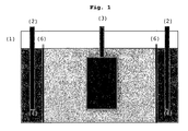
Figur 1 zeigt schematisch das erfindungsgemäße Galvanikbad. Hierin bedeutet (1) das Bad, (2) die Anoden und (3) die Kathode bzw. das zu beschichtende Werkstück. Weiter dargestellt sind der die Anode umgebende Anolyt (4) und der die Kathode umgebende Katholyt (5). Anolyt und Katholyt sind durch eine Filtrationsmembran (6) voneinander getrennt. Die Filtrationsmembran ermöglicht den Betrieb des Bades, begrenzt aber gleichzeitig die Zersetzung der in dem Katholyten befindlichen organischen Bestandteile, insbesondere des Komplexbildners, durch Wanderung an die Anode bzw. in den Anodenraum. Die Komplexbildner können nur vermindert an der Anode reagieren, d.h. sie werden begrenzt zu Carbonaten, Oxalaten, Nitrilen bzw. Cyaniden umgesetzt. Daher beobachtet man bei Betrieb des erfindungsgemäßen Galvanikbads auch keine Phasentrennung. Eine kontinuierliche Reinigung des Bades ist mithin nicht erforderlich.
- FIG. 1 shows schematically the electroplating bath according to the invention. Here, (1) means the bath, (2) the anodes, and (3) the cathode or the workpiece to be coated. Also shown are the anolyte (4) surrounding the anode and the catholyte (5) surrounding the cathode. Anolyte and catholyte are separated by a filtration membrane (6). The filtration membrane allows the operation of the bath, but at the same time limits the decomposition of the organic constituents present in the catholyte, in particular of the complexing agent, by migration to the anode or into the anode space. The complexing agents can react only reduced at the anode, ie they are limited to carbonates, oxalates, nitriles or cyanides implemented. Therefore observed when operating the electroplating bath according to the invention also no phase separation. A continuous cleaning of the bath is therefore not required.
Bei dem erfindungsgemäßen Bad ist der Anodenraum vorzugsweise kleiner ausgestaltet als der Kathodenraum, da dort die wesentlichen Prozesse ablaufen.In the case of the bath according to the invention, the anode space is preferably made smaller than the cathode space, since the essential processes take place there.
Die Erfindung wird durch die nachfolgenden Ausführungsbeispiele näher erläutert.The invention will be explained in more detail by the following embodiments.
Zunächst wurde ein Bad der zur Abscheidung von Zink-Nickel-Legierungen, mit untenstehender Zusammensetzung mit einem Durchsatz von 5 Ah/l betrieben, sodass sich der zunächst höhere Verbrauch nach Beginn des Betriebs des Bades stabilisierte. Hierdurch werden unerwünschte Abscheidungsprozesse vermieden. Dieses Bad wird im Folgenden als "Neuansatz" bezeichnet.Initially, a bath of zinc-nickel alloy composition having the composition below was operated at a rate of 5 Ah / l, so that the initially higher consumption stabilized after the start of the operation of the bath. As a result, unwanted deposition processes are avoided. This bath is hereafter referred to as a "new approach".
Es besteht aus folgenden Komponenten:
- Zink 10,4 g/l (als lösliches ZnO)
Nickel 1,2 g/l (als Nickelsulfat)- NaOH 120 g/l
- Quadrol 35 g/l
- Pyridinium-N-propan-3-
sulfonsäure 1,25 g/l - Polyethylenimin 5 g/l
- Zinc 10.4 g / l (as soluble ZnO)
- Nickel 1.2 g / l (as nickel sulphate)
- NaOH 120 g / l
- Quadrol 35 g / l
- Pyridinium N-propane-3-sulfonic acid 1.25 g / l
- Polyethyleneimine 5 g / l
Des Weiteren wurde ein Bad des gleichen Typs verwendet, das bereits länger betrieben worden war, d.h. einen Durchsatz von > 1000 Ah/l aufwies. Dieses Bad wird im Folgenden als "Altansatz" bezeichnet.Furthermore, a bath of the same type was used, which had been operated for a long time, ie a throughput of> 1000 Ah / l. This bath is hereafter referred to as "old approach".
Beide Bäder wurden jeweils mit und ohne Filtrationsmembran in 5-1-Tanks betrieben Als Filtrationsmembran wurde die von Abwa-Tec erhältlich Polymer-Membran P150F, die eine Porengröße von 0.12 µm aufweist, verwendet. Die Membran wurde in das Bad zwischen Anode und Kathode eingebracht, wobei Anolyt und Katholyt stofflich identisch waren, d.h. es wurde kein spezieller Anolyt zugegeben. Anschließend wurden Eisenbleche (7 x 10 cm), die üblicherweise für Hullzellen-Tests verwendet werden, als zu beschichtende Werkstücke eingesetzt und bei einer Stromdichte von 2 A/dm2 beschichtet. Die Bäder wurden in Seriellschaltung betrieben. Die Bewegung der Eisenbleche erfolgte mechanisch, mit einer Geschwindigkeit von 1,4 m/min.Both baths were operated with and without filtration membrane in 5-liter tanks. The filtration membrane used was the Abwa-Tec polymer membrane P150F, which has a pore size of 0.12 μm. The membrane was placed in the anode to cathode bath with the anolyte and catholyte being identical, ie, no special anolyte was added. Subsequently, iron sheets (7 × 10 cm), which are usually used for Hull cell tests, were used as workpieces to be coated and coated at a current density of 2 A / dm 2 . The baths were operated in serial connection. The movement of the iron sheets was mechanical, at a speed of 1.4 m / min.
Anschließend wurden die Bäder analysiert und regelmäßig ergänzt. Die Nachdosierung der Bäder erfolgte gemäß den Ergebnissen von Hullzellen-Tests jeweils nach ca. 5 Ah/l. Eine bei Produktionsbädern übliche Verschleppung von 12 1 Bad/10.000 Ah wurde ebenfalls berücksichtigt und die Badbestandteile entsprechend ergänzt.Subsequently, the baths were analyzed and supplemented regularly. The replenishment of the baths was carried out according to the results of Hull cell tests after about 5 Ah / l. A carry-over of 12 1 bath / 10,000 Ah, which was common in production baths, was also taken into account and the bath components were supplemented accordingly.
Die Tabelle 2 zeigt die Hullzellen-Schichtdicke bei einem Neuansatz und Altansatz in Abhängigkeit des Durchsatzes mit und ohne Filtrationsmembran. Die Schichtdickenmessungen erfolgten nach Einstellung der Bäder.Table 2 shows the Hull cell layer thickness in a new approach and old approach depending on the throughput with and without filtration membrane. The layer thickness measurements were made after adjustment of the baths.
Es wurde sowohl an Punkten hoher als auch niedriger Stromdichte gemessen. Die Punkte liegen auf den Hullzellenblechen 3 cm vom unteren Rand und 2,5 cm vom linken bzw. rechten seitlichen Rand. Hierbei ist links die hohe Stromdichte (Punkt A) und rechts die niedrige Stromdichte (Punkt B).
Überraschenderweise wurde gefunden, dass die Schichtdicke beim Neuansatz ohne Filtrationsmembran abnimmt, während sie beim Altansatz mit Filtrationsmembran stetig zunimmt.Surprisingly, it was found that the layer thickness decreases in the new batch without filtration membrane, while it steadily increases in the old batch with filtration membrane.
So liegt bei Verwendung einer Filtrationsmembran die durchschnittliche Schichtdicke bei einem Neuansatz im hohen Stromdichtebereich um ca. 35% und im niedrigen Stromdichtebereich um ca. 19% höher als hätte man keine Filtrationsmembran verwendet. Beim Altansatz liegt sie um durchschnittlich 17% bzw. 12% höher als ohne Filtrationsmembran.Thus, when using a filtration membrane, the average layer thickness is about 35% higher in a new batch in the high current density range and about 19% higher in the low current density range as if one had not used a filtration membrane. In the old batch, it is on average 17% and 12% higher than without filtration membrane.
Erstaunlicherweise stellt sich bei einem Altansatz, in den nach einem Durchsatz von > 1000 Ah/l eine Filtrationsmembran eingebracht wurde nach kurzer Zeit eine mit einem Neuansatz vergleichbare Stromausbeute ein.Surprisingly, in the case of an old batch, a filtration membrane is produced after a throughput of> 1000 Ah / l introduced after a short time comparable to a new approach current efficiency.
Die Tabelle 3 zeigt den Durchschnittsverbrauch (1/10.000 Ah) des in dem Bad befindlichen Elektrolyten für erfindungsgemäße Galvanikbäder mit Filtrationsmembran und solche Bäder, die diese Membran nicht aufweisen. Durch den Einsatz der Filtrationsmembrane wurde der Organikverbrauch je nach Zusatz zwischen 12 und 29% verringert.
Glanzzusatz: Pyridin-N-propan-3-sulfonsäure
Brilliant addition: pyridine-N-propane-3-sulfonic acid
Die Zusammensetzung der vorgenannten Bäder wurden nach den oben beschriebenen Tests analysiert. Von besonderem Interesse war dabei ihr Cyanid-Gehalt. Dieser war bei Verwendung der erfindungsgemäßen Bäder mit einer Filtrationsmembran viel geringer als bei Bädern ohne Membran. Ausweislich der nachstehenden Tabelle 4 wies ein Bad ohne die Membran einen Cyanid-Gehalt von 680 mg/l (Neuansatz) bzw. 790 mg/l (Bad mit > 1000 Ah/l), während die entsprechenden, mit einer Membran versehenen Bäder einen Cyanid-Gehalt von 96 mg/l bzw. 190 mg/l aufwiesen.The composition of the aforementioned baths were analyzed according to the tests described above. Of particular interest was their cyanide content. This was much lower when using the baths according to the invention with a filtration membrane as baths without membrane. As shown in Table 4 below, a bath without the membrane had a cyanide content of 680 mg / L (new batch) and 790 mg / L (bath of> 1000 Ah / L), respectively, while the corresponding membrane baths contained a cyanide Content of 96 mg / L or 190 mg / L.
Überraschenderweise wurde gefunden, dass der Cyanid-Gehalt eines Altansatzes, d.h. eines Bades mit > 1000 Ah/l verringert werden kann, wenn dieses mit einer Filtrationsmembran versehen und betrieben wird. Bei einem solchen Bad wurde beispielsweise der Cyanid-Gehalt von 670 mg/l auf 190 mg/l verringert.
Bei der Durchführung der vorbeschriebenen Tests wurde auch die Farbe der Bäder beurteilt. Dabei wurde festgestellt, dass sich die Farbe eines frisch angesetzten Bades ohne Membran von anfangs violett-orange in braun innerhalb von 15 Ah/l änderte, wobei sie bei Verwendung einer Filtrationsmembran über die gesamte Zeit hin violett bzw. violett-orange blieb. Der Altansatz blieb ohne Verwendung einer Membran braun und die Farbe schlug nach orange-braun nach 15 Ah/l bei Verwendung einer Filtrationsmembran um. Violett ist auch die Farbe frisch angesetzter Bäder, die dann nach orange (nach einigen Ah/l) und bei hohem Durchsatz in braun umschlägt.In carrying out the above tests, the color of the baths was also evaluated. It was found that the color of a freshly prepared bath without membrane changed from initially violet-orange to brown within 15 Ah / l, whereby it remained purple or violet-orange over the entire time when using a filtration membrane. The old batch remained brown without using a membrane and the color changed to orange-brown after 15 Ah / l using a filtration membrane. Violet is also the color of freshly applied baths, which then turn to orange (after a few Ah / l) and at high throughput in brown.
Schließlich wurde die Spannung zwischen Anode und Kathode gemessen. Sie betrug etwa 3 V und lag bei beiden Ansätzen nur etwa 50-100 mV höher bei Verwendung einer Filtrationsmembran. Verwendet man anstelle der Filtrationsmembran eine Ionenaustauschermembran, wie sie in der
Zusammenfassend lässt sich feststellen, dass die Verwendung von Filtrationsmembranen gegenüber der Verwendung von Ionenaustauschermembranen zahlreiche Vorteile bietet. So ist das damit durchgeführte Beschichtungsverfahren kostengünstiger, da keine platinierten Anoden verwendet werden müssen, Katholyt und Anolyt die gleiche Zusammensetzung aufweisen können und somit auch kein Kreislauf für den Anolyten erforderlich ist.In summary, the use of filtration membranes over the use of ion exchange membranes offers many advantages. Thus, the coating process carried out therewith is more cost-effective, since no platinized anodes have to be used, catholyte and anolyte can have the same composition, and thus no circulation for the anolyte is required.
Im Vergleich zu dem Betrieb eines Galvanikbads ohne Membran ist die Stromausbeute höher und der Verbrauch geringer. Schließlich können Zersetzungsprodukte und insbesondere Cyanide verringert bzw. deren Konzentration herabgesetzt und die Qualität der aus dem Bad abgeschiedenen Schichten verbessert werden.Compared to the operation of a plating bath without a membrane, the current efficiency is higher and the consumption is lower. Finally, decomposition products and in particular cyanides can be reduced or their concentration lowered and the quality of the layers deposited from the bath can be improved.
- (1)(1)
- Alkalisches GalvanikbadAlkaline electroplating bath
- (2)(2)
- Anodeanode
- (3)(3)
- Kathodecathode
- (4)(4)
- Anolytanolyte
- (5)(5)
- Katholytcatholyte
- (6)(6)
- Filtrationsmembranfiltration membrane
Claims (11)
Priority Applications (15)
| Application Number | Priority Date | Filing Date | Title |
|---|---|---|---|
| DE502005007138T DE502005007138D1 (en) | 2005-04-26 | 2005-04-26 | Alkaline electroplating bath with a filtration membrane |
| ES09152660.8T ES2574158T3 (en) | 2005-04-26 | 2005-04-26 | Galvanic alkaline bath with a filtration membrane |
| AT05009127T ATE429528T1 (en) | 2005-04-26 | 2005-04-26 | ALKALINE GALVANIC BATH WITH A FILTRATION MEMBRANE |
| EP05009127A EP1717353B1 (en) | 2005-04-26 | 2005-04-26 | Alkaline galvanizing bath comprising a filtration membrane |
| ES05009127T ES2324169T3 (en) | 2005-04-26 | 2005-04-26 | ALCALINE GALVANIC BATHROOM WITH A FILTRATION MEMBRANE. |
| EP09152660.8A EP2050841B1 (en) | 2005-04-26 | 2005-04-26 | Alkaline electroplating bath with a filtration membrane |
| CN201510173898.7A CN104911676B (en) | 2005-04-26 | 2006-04-26 | Alkaline electro plating bath with filtration membrane |
| US11/912,591 US8293092B2 (en) | 2005-04-26 | 2006-04-26 | Alkaline electroplating bath having a filtration membrane |
| KR1020077019889A KR101301275B1 (en) | 2005-04-26 | 2006-04-26 | Alkaline Electroplating Bath Having a Filtration Membrane |
| PCT/EP2006/003883 WO2006114305A1 (en) | 2005-04-26 | 2006-04-26 | Alkaline electroplating bath having a filtration membrane |
| BRPI0610765A BRPI0610765B1 (en) | 2005-04-26 | 2006-04-26 | electroplating alkaline bath having a filtration membrane |
| CN201510173915.7A CN104911651A (en) | 2005-04-26 | 2006-04-26 | Alkaline electroplating bath having a filtration membrane |
| JP2008508150A JP4955657B2 (en) | 2005-04-26 | 2006-04-26 | Alkaline electroplating bath with filtration membrane |
| CNA2006800094924A CN101146934A (en) | 2005-04-26 | 2006-04-26 | Alkaline galvanizing bath comprising a filtration membrane |
| CA2600273A CA2600273C (en) | 2005-04-26 | 2006-04-26 | Alkaline electroplating bath having a filtration membrane |
Applications Claiming Priority (1)
| Application Number | Priority Date | Filing Date | Title |
|---|---|---|---|
| EP05009127A EP1717353B1 (en) | 2005-04-26 | 2005-04-26 | Alkaline galvanizing bath comprising a filtration membrane |
Related Child Applications (1)
| Application Number | Title | Priority Date | Filing Date |
|---|---|---|---|
| EP09152660.8A Division EP2050841B1 (en) | 2005-04-26 | 2005-04-26 | Alkaline electroplating bath with a filtration membrane |
Publications (2)
| Publication Number | Publication Date |
|---|---|
| EP1717353A1 true EP1717353A1 (en) | 2006-11-02 |
| EP1717353B1 EP1717353B1 (en) | 2009-04-22 |
Family
ID=35530823
Family Applications (2)
| Application Number | Title | Priority Date | Filing Date |
|---|---|---|---|
| EP05009127A Active EP1717353B1 (en) | 2005-04-26 | 2005-04-26 | Alkaline galvanizing bath comprising a filtration membrane |
| EP09152660.8A Revoked EP2050841B1 (en) | 2005-04-26 | 2005-04-26 | Alkaline electroplating bath with a filtration membrane |
Family Applications After (1)
| Application Number | Title | Priority Date | Filing Date |
|---|---|---|---|
| EP09152660.8A Revoked EP2050841B1 (en) | 2005-04-26 | 2005-04-26 | Alkaline electroplating bath with a filtration membrane |
Country Status (11)
| Country | Link |
|---|---|
| US (1) | US8293092B2 (en) |
| EP (2) | EP1717353B1 (en) |
| JP (1) | JP4955657B2 (en) |
| KR (1) | KR101301275B1 (en) |
| CN (3) | CN101146934A (en) |
| AT (1) | ATE429528T1 (en) |
| BR (1) | BRPI0610765B1 (en) |
| CA (1) | CA2600273C (en) |
| DE (1) | DE502005007138D1 (en) |
| ES (2) | ES2574158T3 (en) |
| WO (1) | WO2006114305A1 (en) |
Cited By (5)
| Publication number | Priority date | Publication date | Assignee | Title |
|---|---|---|---|---|
| WO2009044266A2 (en) * | 2007-10-05 | 2009-04-09 | Create New Technology S.R.L. | System and method of plating metal alloys by using galvanic technology |
| EP2184384A1 (en) | 2008-11-11 | 2010-05-12 | Enthone, Inc. | Galvanic bath and method for deposition of zinc-containing layers |
| EP2384800A1 (en) | 2010-05-07 | 2011-11-09 | Dr.Ing. Max Schlötter GmbH & Co. KG | Regeneration of alkaline zinc electrolytes by removing cyanidiones |
| EP3358045A1 (en) | 2017-02-07 | 2018-08-08 | Dr.Ing. Max Schlötter GmbH & Co. KG | Method for the galvanic deposition of zinc and zinc alloy layers from an alkaline coating bath with reduced degradation of organic bath additives |
| EP3415665A1 (en) | 2017-06-14 | 2018-12-19 | Dr.Ing. Max Schlötter GmbH & Co. KG | Method for the galvanic deposition of zinc-nickel alloy layers from an alkaline zinc-nickel alloy bath with reduced degradation of additives |
Families Citing this family (16)
| Publication number | Priority date | Publication date | Assignee | Title |
|---|---|---|---|---|
| US20090107545A1 (en) * | 2006-10-09 | 2009-04-30 | Soltaix, Inc. | Template for pyramidal three-dimensional thin-film solar cell manufacturing and methods of use |
| US8177944B2 (en) * | 2007-12-04 | 2012-05-15 | Ebara Corporation | Plating apparatus and plating method |
| IT1405319B1 (en) * | 2010-12-27 | 2014-01-03 | Fontana R D S R L | COATING PROCESS OF THREADED METAL PARTS |
| KR101420865B1 (en) * | 2012-10-12 | 2014-07-18 | 주식회사 익스톨 | Metal Plating Device |
| EP2784189A1 (en) | 2013-03-28 | 2014-10-01 | Coventya SAS | Electroplating bath for zinc-iron alloys, method for depositing zinc-iron alloy on a device and such a device |
| US11649558B2 (en) | 2015-03-13 | 2023-05-16 | Okuno Chemical Industries Co., Ltd. | Electrolytic stripping agent for jig |
| JP5830202B1 (en) | 2015-07-22 | 2015-12-09 | ディップソール株式会社 | Zinc alloy plating method |
| MX368366B (en) * | 2015-07-22 | 2019-09-30 | Dipsol Chem | Zinc alloy plating method. |
| EP3464684A4 (en) * | 2016-05-24 | 2020-03-11 | Coventya Inc. | Ternary zinc-nickel-iron alloys and alkaline electrolytes for plating such alloys |
| WO2018018161A1 (en) * | 2016-07-29 | 2018-02-01 | Simon Fraser University | Methods of electrochemical deposition |
| PL3461933T3 (en) * | 2017-09-28 | 2020-03-31 | Atotech Deutschland Gmbh | Method for electrolytically depositing a zinc-nickel alloy layer on at least a substrate to be treated |
| US11165091B2 (en) | 2018-01-23 | 2021-11-02 | City University Of Hong Kong | Battery system and a method of forming a battery |
| US20220119978A1 (en) * | 2019-01-24 | 2022-04-21 | Atotech Deutschland Gmbh | Membrane anode system for electrolytic zinc-nickel alloy deposition |
| EP3715506A4 (en) | 2019-02-15 | 2021-04-14 | Dipsol Chemicals Co., Ltd. | Zinc or zinc alloy electroplating method and system |
| RU2712582C1 (en) * | 2019-07-16 | 2020-01-29 | Федеральное государственное бюджетное образовательное учреждение высшего образования "Ивановский государственный химико-технологический университет" | Electrolyte for electrodeposition of zinc-iron coatings |
| EP4273303A1 (en) * | 2022-05-05 | 2023-11-08 | Atotech Deutschland GmbH & Co. KG | Method for depositing a zinc-nickel alloy on a substrate, an aqueous zinc-nickel deposition bath, a brightening agent and use thereof |
Citations (3)
| Publication number | Priority date | Publication date | Assignee | Title |
|---|---|---|---|---|
| US3974049A (en) * | 1973-08-03 | 1976-08-10 | Parel. Societe Anonyme | Electrochemical process |
| EP1365046A1 (en) * | 2002-05-16 | 2003-11-26 | UNIVERSITE PAUL SABATIER (TOULOUSE III) Etablissement public a caractère scientifique, culturel et professionnel | Process for protecting a steel substrate or an alluminium alloy substrate against corrosion, permitting to provide it with good tribological properties, and resulting substrate |
| WO2005073438A1 (en) * | 2003-12-31 | 2005-08-11 | Coventya Sas | Zinc or zinc alloy deposition installation |
Family Cites Families (25)
| Publication number | Priority date | Publication date | Assignee | Title |
|---|---|---|---|---|
| GB381931A (en) * | 1931-07-11 | 1932-10-11 | Mond Nickel Co Ltd | Improvements relating to electro-plating and the electrodeposition of metals |
| US3945900A (en) | 1972-05-02 | 1976-03-23 | Dorr-Oliver Incorporated | Electro ultrafiltration process and apparatus |
| US4250002A (en) * | 1979-09-19 | 1981-02-10 | Hooker Chemicals & Plastics Corp. | Polymeric microporous separators for use in electrolytic processes and devices |
| US4421611A (en) | 1982-09-30 | 1983-12-20 | Mcgean-Rohco, Inc. | Acetylenic compositions and nickel plating baths containing same |
| JPS6353285A (en) | 1986-08-22 | 1988-03-07 | Nippon Hyomen Kagaku Kk | Zinc-nickel alloy plating solution |
| JPH01116094A (en) * | 1987-10-28 | 1989-05-09 | Eagle Ind Co Ltd | Diaphragm plating method |
| JPH02141596A (en) * | 1988-11-21 | 1990-05-30 | Yuken Kogyo Kk | Zincate-type zinc alloy plating bath |
| JPH0444375A (en) * | 1990-06-12 | 1992-02-14 | Zexel Corp | Alignment device for laser oscillator |
| US5443727A (en) | 1990-10-30 | 1995-08-22 | Minnesota Mining And Manufacturing Company | Articles having a polymeric shell and method for preparing same |
| US5082538A (en) | 1991-01-09 | 1992-01-21 | Eltech Systems Corporation | Process for replenishing metals in aqueous electrolyte solutions |
| CN2175238Y (en) * | 1993-09-29 | 1994-08-24 | 北京科技大学 | Positive plate of electroplating bath made of zinc-nickel alloy |
| US5417840A (en) | 1993-10-21 | 1995-05-23 | Mcgean-Rohco, Inc. | Alkaline zinc-nickel alloy plating baths |
| US5631102A (en) * | 1996-02-12 | 1997-05-20 | Wilson Greatbatch Ltd. | Separator insert for electrochemical cells |
| JPH11200099A (en) | 1998-01-08 | 1999-07-27 | Toyo Kohan Co Ltd | Plating method and plating apparatus using insoluble anode |
| DE19834353C2 (en) * | 1998-07-30 | 2000-08-17 | Hillebrand Walter Gmbh & Co Kg | Alkaline zinc-nickel bath |
| DE19840019C1 (en) | 1998-09-02 | 2000-03-16 | Atotech Deutschland Gmbh | Aqueous alkaline cyanide-free bath for the electrodeposition of zinc or zinc alloy coatings and method |
| JP2000087299A (en) * | 1998-09-08 | 2000-03-28 | Ebara Corp | Substrate plating apparatus |
| US6383352B1 (en) | 1998-11-13 | 2002-05-07 | Mykrolis Corporation | Spiral anode for metal plating baths |
| JP4060012B2 (en) * | 1999-07-19 | 2008-03-12 | 日本エレクトロプレイテイング・エンジニヤース株式会社 | Cup type plating equipment |
| DE60023190T3 (en) | 2000-06-15 | 2016-03-10 | Coventya, Inc. | ZINC-NICKEL-electroplating |
| DE10225203A1 (en) | 2002-06-06 | 2003-12-18 | Goema Ag | Method and device for returning rinsing water and cleaning a process bath |
| WO2004011698A1 (en) | 2002-07-25 | 2004-02-05 | Shinryo Electronics Co., Ltd. | Tin-silver-copper plating solution, plating film containing the same, and method for forming the plating film |
| AU2003239929A1 (en) * | 2003-06-03 | 2005-01-04 | Coventya Sas | Zinc and zinc-alloy electroplating |
| JP4120497B2 (en) * | 2003-06-27 | 2008-07-16 | Jfeスチール株式会社 | Electro-galvanized steel sheet |
| US7442286B2 (en) * | 2004-02-26 | 2008-10-28 | Atotech Deutschland Gmbh | Articles with electroplated zinc-nickel ternary and higher alloys, electroplating baths, processes and systems for electroplating such alloys |
-
2005
- 2005-04-26 ES ES09152660.8T patent/ES2574158T3/en active Active
- 2005-04-26 AT AT05009127T patent/ATE429528T1/en not_active IP Right Cessation
- 2005-04-26 ES ES05009127T patent/ES2324169T3/en active Active
- 2005-04-26 EP EP05009127A patent/EP1717353B1/en active Active
- 2005-04-26 DE DE502005007138T patent/DE502005007138D1/en active Active
- 2005-04-26 EP EP09152660.8A patent/EP2050841B1/en not_active Revoked
-
2006
- 2006-04-26 KR KR1020077019889A patent/KR101301275B1/en active IP Right Grant
- 2006-04-26 CN CNA2006800094924A patent/CN101146934A/en active Pending
- 2006-04-26 CN CN201510173898.7A patent/CN104911676B/en active Active
- 2006-04-26 US US11/912,591 patent/US8293092B2/en active Active
- 2006-04-26 JP JP2008508150A patent/JP4955657B2/en active Active
- 2006-04-26 BR BRPI0610765A patent/BRPI0610765B1/en active IP Right Grant
- 2006-04-26 CN CN201510173915.7A patent/CN104911651A/en active Pending
- 2006-04-26 CA CA2600273A patent/CA2600273C/en active Active
- 2006-04-26 WO PCT/EP2006/003883 patent/WO2006114305A1/en active Application Filing
Patent Citations (3)
| Publication number | Priority date | Publication date | Assignee | Title |
|---|---|---|---|---|
| US3974049A (en) * | 1973-08-03 | 1976-08-10 | Parel. Societe Anonyme | Electrochemical process |
| EP1365046A1 (en) * | 2002-05-16 | 2003-11-26 | UNIVERSITE PAUL SABATIER (TOULOUSE III) Etablissement public a caractère scientifique, culturel et professionnel | Process for protecting a steel substrate or an alluminium alloy substrate against corrosion, permitting to provide it with good tribological properties, and resulting substrate |
| WO2005073438A1 (en) * | 2003-12-31 | 2005-08-11 | Coventya Sas | Zinc or zinc alloy deposition installation |
Cited By (8)
| Publication number | Priority date | Publication date | Assignee | Title |
|---|---|---|---|---|
| WO2009044266A2 (en) * | 2007-10-05 | 2009-04-09 | Create New Technology S.R.L. | System and method of plating metal alloys by using galvanic technology |
| WO2009044266A3 (en) * | 2007-10-05 | 2010-01-21 | Create New Technology S.R.L. | System and method of plating metal alloys by using galvanic technology |
| US8668817B2 (en) | 2007-10-05 | 2014-03-11 | Creat New Technology S.R.L. | System and method of plating metal alloys by using galvanic technology |
| EP2184384A1 (en) | 2008-11-11 | 2010-05-12 | Enthone, Inc. | Galvanic bath and method for deposition of zinc-containing layers |
| EP2384800A1 (en) | 2010-05-07 | 2011-11-09 | Dr.Ing. Max Schlötter GmbH & Co. KG | Regeneration of alkaline zinc electrolytes by removing cyanidiones |
| EP3358045A1 (en) | 2017-02-07 | 2018-08-08 | Dr.Ing. Max Schlötter GmbH & Co. KG | Method for the galvanic deposition of zinc and zinc alloy layers from an alkaline coating bath with reduced degradation of organic bath additives |
| WO2018146041A1 (en) | 2017-02-07 | 2018-08-16 | Dr.-Ing. Max Schlötter Gmbh & Co. Kg | Method for electrodepositing zinc and zinc alloy coatings from an alkaline coating bath with reduced depletion of organic bath additives |
| EP3415665A1 (en) | 2017-06-14 | 2018-12-19 | Dr.Ing. Max Schlötter GmbH & Co. KG | Method for the galvanic deposition of zinc-nickel alloy layers from an alkaline zinc-nickel alloy bath with reduced degradation of additives |
Also Published As
| Publication number | Publication date |
|---|---|
| CN104911676A (en) | 2015-09-16 |
| CA2600273C (en) | 2014-08-12 |
| EP2050841A1 (en) | 2009-04-22 |
| EP2050841B1 (en) | 2016-05-11 |
| ATE429528T1 (en) | 2009-05-15 |
| CN101146934A (en) | 2008-03-19 |
| BRPI0610765B1 (en) | 2017-04-04 |
| DE502005007138D1 (en) | 2009-06-04 |
| CN104911676B (en) | 2017-11-17 |
| US20090107845A1 (en) | 2009-04-30 |
| US8293092B2 (en) | 2012-10-23 |
| KR101301275B1 (en) | 2013-08-29 |
| ES2324169T3 (en) | 2009-07-31 |
| BRPI0610765A2 (en) | 2010-07-20 |
| KR20070122454A (en) | 2007-12-31 |
| JP4955657B2 (en) | 2012-06-20 |
| EP1717353B1 (en) | 2009-04-22 |
| JP2008539329A (en) | 2008-11-13 |
| CN104911651A (en) | 2015-09-16 |
| CA2600273A1 (en) | 2006-11-02 |
| WO2006114305A1 (en) | 2006-11-02 |
| ES2574158T3 (en) | 2016-06-15 |
Similar Documents
| Publication | Publication Date | Title |
|---|---|---|
| EP1717353B1 (en) | Alkaline galvanizing bath comprising a filtration membrane | |
| EP2116634B1 (en) | Modified copper-tin electrolyte and method of depositing bronze layers | |
| EP1408141B1 (en) | Process and electrolyte for the galvanic deposition of bronze | |
| DE102015107748A1 (en) | Electroplating cell and method of forming a metal coating | |
| DE4023444A1 (en) | Cyanide-free copper plating process - where a portion of the plating bath is electrolysed by an independently-controlled insol. anode to reduce bath impurities | |
| EP3481976B1 (en) | Method for the galvanic deposition of zinc and zinc alloy layers from an alkaline coating bath with reduced degradation of organic bath additives | |
| EP2235236B1 (en) | Galvanic bath, method for galvanic deposition, and use of a bipolar membrane for separating in a galvanic bath | |
| DE102010044551A1 (en) | Anode and their use in an alkaline electroplating bath | |
| EP1213372B1 (en) | Process and arrangement for the galvanic deposition of nickel, cobalt, nickel alloys or cobalt alloys with periodic current pulses and use of the process | |
| EP0797693A1 (en) | Laminated material for sliding components and method and means for its production | |
| EP3250733B1 (en) | Production of chromium layers on intaglio printing cylinders | |
| WO2012059473A1 (en) | Method for depositing hard chromium from cr(vi)-free electrolytes | |
| DE3029364A1 (en) | PROCESS FOR THE MANUFACTURE OF LOW HYDROGEN OVERVOLTAGE CATHODE AND THEIR USE | |
| EP0801692A2 (en) | Electroplating plant | |
| EP3666928A1 (en) | Process of fabricating a metal band having a chromium and chromium oxide coating using a trivalent chromium containing electrolyte | |
| DE2527386A1 (en) | CATHODE SURFACES WITH LOW HYDROGEN OVERVOLTAGE | |
| DE102009023124A1 (en) | Process for the galvanic copper coating and apparatus for carrying out such a process | |
| EP1080252B1 (en) | Method for electro copperplating substrates | |
| EP2384800B1 (en) | Regeneration of alkaline zinc nickel electrolytes by removing cyanide ions | |
| DE102019202899B3 (en) | Aqueous formulation for producing a layer of gold and silver | |
| DE2929305C2 (en) | Process and device for the continuous electrodeposition of manganese on steel | |
| DE102012004348A1 (en) | Additive for improving the layer thickness distribution in galvanic drum electrolytes | |
| EP2878711A1 (en) | Method for the galvanic deposition of nickel and corresponding electrolyte | |
| WO2023041670A1 (en) | Chromium-indium, chromium-bismuth and chromium-antimony coatings, method for the production and use thereof | |
| AT222969B (en) | Method and solution for the electrolytic deposition of an alloy on metal surfaces |
Legal Events
| Date | Code | Title | Description |
|---|---|---|---|
| PUAI | Public reference made under article 153(3) epc to a published international application that has entered the european phase |
Free format text: ORIGINAL CODE: 0009012 |
|
| AK | Designated contracting states |
Kind code of ref document: A1 Designated state(s): AT BE BG CH CY CZ DE DK EE ES FI FR GB GR HU IE IS IT LI LT LU MC NL PL PT RO SE SI SK TR |
|
| AX | Request for extension of the european patent |
Extension state: AL BA HR LV MK YU |
|
| 17P | Request for examination filed |
Effective date: 20060926 |
|
| AKX | Designation fees paid |
Designated state(s): AT BE BG CH CY CZ DE DK EE ES FI FR GB GR HU IE IS IT LI LT LU MC NL PL PT RO SE SI SK TR |
|
| 17Q | First examination report despatched |
Effective date: 20070803 |
|
| GRAP | Despatch of communication of intention to grant a patent |
Free format text: ORIGINAL CODE: EPIDOSNIGR1 |
|
| GRAS | Grant fee paid |
Free format text: ORIGINAL CODE: EPIDOSNIGR3 |
|
| GRAA | (expected) grant |
Free format text: ORIGINAL CODE: 0009210 |
|
| AK | Designated contracting states |
Kind code of ref document: B1 Designated state(s): AT BE BG CH CY CZ DE DK EE ES FI FR GB GR HU IE IS IT LI LT LU MC NL PL PT RO SE SI SK TR |
|
| REG | Reference to a national code |
Ref country code: GB Ref legal event code: FG4D Free format text: NOT ENGLISH |
|
| REG | Reference to a national code |
Ref country code: CH Ref legal event code: EP |
|
| REG | Reference to a national code |
Ref country code: IE Ref legal event code: FG4D |
|
| REF | Corresponds to: |
Ref document number: 502005007138 Country of ref document: DE Date of ref document: 20090604 Kind code of ref document: P |
|
| REG | Reference to a national code |
Ref country code: ES Ref legal event code: FG2A Ref document number: 2324169 Country of ref document: ES Kind code of ref document: T3 |
|
| NLV1 | Nl: lapsed or annulled due to failure to fulfill the requirements of art. 29p and 29m of the patents act | ||
| PG25 | Lapsed in a contracting state [announced via postgrant information from national office to epo] |
Ref country code: PT Free format text: LAPSE BECAUSE OF FAILURE TO SUBMIT A TRANSLATION OF THE DESCRIPTION OR TO PAY THE FEE WITHIN THE PRESCRIBED TIME-LIMIT Effective date: 20090822 Ref country code: FI Free format text: LAPSE BECAUSE OF FAILURE TO SUBMIT A TRANSLATION OF THE DESCRIPTION OR TO PAY THE FEE WITHIN THE PRESCRIBED TIME-LIMIT Effective date: 20090422 Ref country code: LT Free format text: LAPSE BECAUSE OF FAILURE TO SUBMIT A TRANSLATION OF THE DESCRIPTION OR TO PAY THE FEE WITHIN THE PRESCRIBED TIME-LIMIT Effective date: 20090422 |
|
| BERE | Be: lapsed |
Owner name: ATOTECH DEUTSCHLAND G.M.B.H. Effective date: 20090430 |
|
| PG25 | Lapsed in a contracting state [announced via postgrant information from national office to epo] |
Ref country code: IS Free format text: LAPSE BECAUSE OF FAILURE TO SUBMIT A TRANSLATION OF THE DESCRIPTION OR TO PAY THE FEE WITHIN THE PRESCRIBED TIME-LIMIT Effective date: 20090822 Ref country code: PL Free format text: LAPSE BECAUSE OF FAILURE TO SUBMIT A TRANSLATION OF THE DESCRIPTION OR TO PAY THE FEE WITHIN THE PRESCRIBED TIME-LIMIT Effective date: 20090422 Ref country code: SI Free format text: LAPSE BECAUSE OF FAILURE TO SUBMIT A TRANSLATION OF THE DESCRIPTION OR TO PAY THE FEE WITHIN THE PRESCRIBED TIME-LIMIT Effective date: 20090422 Ref country code: SE Free format text: LAPSE BECAUSE OF FAILURE TO SUBMIT A TRANSLATION OF THE DESCRIPTION OR TO PAY THE FEE WITHIN THE PRESCRIBED TIME-LIMIT Effective date: 20090722 Ref country code: NL Free format text: LAPSE BECAUSE OF FAILURE TO SUBMIT A TRANSLATION OF THE DESCRIPTION OR TO PAY THE FEE WITHIN THE PRESCRIBED TIME-LIMIT Effective date: 20090422 |
|
| REG | Reference to a national code |
Ref country code: CH Ref legal event code: PL |
|
| REG | Reference to a national code |
Ref country code: IE Ref legal event code: FD4D |
|
| PG25 | Lapsed in a contracting state [announced via postgrant information from national office to epo] |
Ref country code: EE Free format text: LAPSE BECAUSE OF FAILURE TO SUBMIT A TRANSLATION OF THE DESCRIPTION OR TO PAY THE FEE WITHIN THE PRESCRIBED TIME-LIMIT Effective date: 20090422 Ref country code: CH Free format text: LAPSE BECAUSE OF NON-PAYMENT OF DUE FEES Effective date: 20090430 Ref country code: RO Free format text: LAPSE BECAUSE OF FAILURE TO SUBMIT A TRANSLATION OF THE DESCRIPTION OR TO PAY THE FEE WITHIN THE PRESCRIBED TIME-LIMIT Effective date: 20090422 Ref country code: LI Free format text: LAPSE BECAUSE OF NON-PAYMENT OF DUE FEES Effective date: 20090430 Ref country code: IE Free format text: LAPSE BECAUSE OF FAILURE TO SUBMIT A TRANSLATION OF THE DESCRIPTION OR TO PAY THE FEE WITHIN THE PRESCRIBED TIME-LIMIT Effective date: 20090422 Ref country code: DK Free format text: LAPSE BECAUSE OF FAILURE TO SUBMIT A TRANSLATION OF THE DESCRIPTION OR TO PAY THE FEE WITHIN THE PRESCRIBED TIME-LIMIT Effective date: 20090422 |
|
| PG25 | Lapsed in a contracting state [announced via postgrant information from national office to epo] |
Ref country code: SK Free format text: LAPSE BECAUSE OF FAILURE TO SUBMIT A TRANSLATION OF THE DESCRIPTION OR TO PAY THE FEE WITHIN THE PRESCRIBED TIME-LIMIT Effective date: 20090422 |
|
| PLBE | No opposition filed within time limit |
Free format text: ORIGINAL CODE: 0009261 |
|
| STAA | Information on the status of an ep patent application or granted ep patent |
Free format text: STATUS: NO OPPOSITION FILED WITHIN TIME LIMIT |
|
| GBPC | Gb: european patent ceased through non-payment of renewal fee |
Effective date: 20090722 |
|
| 26N | No opposition filed |
Effective date: 20100125 |
|
| PG25 | Lapsed in a contracting state [announced via postgrant information from national office to epo] |
Ref country code: BG Free format text: LAPSE BECAUSE OF FAILURE TO SUBMIT A TRANSLATION OF THE DESCRIPTION OR TO PAY THE FEE WITHIN THE PRESCRIBED TIME-LIMIT Effective date: 20090722 |
|
| PG25 | Lapsed in a contracting state [announced via postgrant information from national office to epo] |
Ref country code: MC Free format text: LAPSE BECAUSE OF NON-PAYMENT OF DUE FEES Effective date: 20090430 |
|
| PG25 | Lapsed in a contracting state [announced via postgrant information from national office to epo] |
Ref country code: GB Free format text: LAPSE BECAUSE OF NON-PAYMENT OF DUE FEES Effective date: 20090722 Ref country code: BE Free format text: LAPSE BECAUSE OF NON-PAYMENT OF DUE FEES Effective date: 20090430 |
|
| PG25 | Lapsed in a contracting state [announced via postgrant information from national office to epo] |
Ref country code: AT Free format text: LAPSE BECAUSE OF NON-PAYMENT OF DUE FEES Effective date: 20090426 |
|
| PG25 | Lapsed in a contracting state [announced via postgrant information from national office to epo] |
Ref country code: GR Free format text: LAPSE BECAUSE OF FAILURE TO SUBMIT A TRANSLATION OF THE DESCRIPTION OR TO PAY THE FEE WITHIN THE PRESCRIBED TIME-LIMIT Effective date: 20090723 |
|
| PG25 | Lapsed in a contracting state [announced via postgrant information from national office to epo] |
Ref country code: LU Free format text: LAPSE BECAUSE OF NON-PAYMENT OF DUE FEES Effective date: 20090426 |
|
| PG25 | Lapsed in a contracting state [announced via postgrant information from national office to epo] |
Ref country code: HU Free format text: LAPSE BECAUSE OF FAILURE TO SUBMIT A TRANSLATION OF THE DESCRIPTION OR TO PAY THE FEE WITHIN THE PRESCRIBED TIME-LIMIT Effective date: 20091023 |
|
| PG25 | Lapsed in a contracting state [announced via postgrant information from national office to epo] |
Ref country code: TR Free format text: LAPSE BECAUSE OF FAILURE TO SUBMIT A TRANSLATION OF THE DESCRIPTION OR TO PAY THE FEE WITHIN THE PRESCRIBED TIME-LIMIT Effective date: 20090422 |
|
| PG25 | Lapsed in a contracting state [announced via postgrant information from national office to epo] |
Ref country code: CY Free format text: LAPSE BECAUSE OF FAILURE TO SUBMIT A TRANSLATION OF THE DESCRIPTION OR TO PAY THE FEE WITHIN THE PRESCRIBED TIME-LIMIT Effective date: 20090422 |
|
| REG | Reference to a national code |
Ref country code: FR Ref legal event code: PLFP Year of fee payment: 12 |
|
| REG | Reference to a national code |
Ref country code: FR Ref legal event code: PLFP Year of fee payment: 13 |
|
| REG | Reference to a national code |
Ref country code: FR Ref legal event code: PLFP Year of fee payment: 14 |
|
| PGFP | Annual fee paid to national office [announced via postgrant information from national office to epo] |
Ref country code: IT Payment date: 20230426 Year of fee payment: 19 Ref country code: FR Payment date: 20230420 Year of fee payment: 19 Ref country code: ES Payment date: 20230627 Year of fee payment: 19 Ref country code: DE Payment date: 20230420 Year of fee payment: 19 Ref country code: CZ Payment date: 20230419 Year of fee payment: 19 |