EP1717103B1 - Rearview mirror for a motor vehicle - Google Patents
Rearview mirror for a motor vehicle Download PDFInfo
- Publication number
- EP1717103B1 EP1717103B1 EP20060008147 EP06008147A EP1717103B1 EP 1717103 B1 EP1717103 B1 EP 1717103B1 EP 20060008147 EP20060008147 EP 20060008147 EP 06008147 A EP06008147 A EP 06008147A EP 1717103 B1 EP1717103 B1 EP 1717103B1
- Authority
- EP
- European Patent Office
- Prior art keywords
- rearview mirror
- contact
- glass
- mirror
- contact element
- Prior art date
- Legal status (The legal status is an assumption and is not a legal conclusion. Google has not performed a legal analysis and makes no representation as to the accuracy of the status listed.)
- Active
Links
Images


Classifications
-
- B—PERFORMING OPERATIONS; TRANSPORTING
- B60—VEHICLES IN GENERAL
- B60R—VEHICLES, VEHICLE FITTINGS, OR VEHICLE PARTS, NOT OTHERWISE PROVIDED FOR
- B60R1/00—Optical viewing arrangements; Real-time viewing arrangements for drivers or passengers using optical image capturing systems, e.g. cameras or video systems specially adapted for use in or on vehicles
- B60R1/02—Rear-view mirror arrangements
- B60R1/06—Rear-view mirror arrangements mounted on vehicle exterior
- B60R1/062—Rear-view mirror arrangements mounted on vehicle exterior with remote control for adjusting position
- B60R1/07—Rear-view mirror arrangements mounted on vehicle exterior with remote control for adjusting position by electrically powered actuators
Definitions
- the invention relates to a rearview mirror for a motor vehicle according to the preamble of claim 1.
- Generic rearview mirrors are used in motor vehicles as an interior rearview mirror or as an exterior rearview mirror to allow the driver in the mirror glass of the glass assembly to observe the subsequent traffic.
- a large number of electrical functional elements are integrated into the rearview mirrors. These may be lighting devices, antennas, mirror heaters, electro-chromatically dimmable mirror glasses or other additional functional elements.
- a motorized adjustment of the glass assembly by means of a Glasverstellantriebs is often provided, the drive motors must be electrically connected to the electrical system.
- the lines to the various functional elements of the rearview mirror can be separated at suitable locations, contact elements being provided at each of the line ends.
- these contact points are then contacted with one another in order to ensure the electrical functionality of the electrical functional elements.
- the US 6,247,823 B1 describes a rearview mirror with a plug-in contact.
- the plug of the plug-in contact are aligned such that insertion of the plug is realized in correspondingly arranged sockets by the joining movement.
- the EP 1 370 443 B1 describes a sliding contact for automatically connecting a mirror heater during assembly of the mirror glass on a support plate.
- a disadvantage of the known rear-view mirrors is that the mounting of the rearview mirror is made considerably more difficult by contacting the contact points.
- cable tails are provided with connectors on the various functional elements, which must be mounted by hand during assembly of the rearview mirror. By this separate installation of the contact elements of the assembly effort is significantly increased.
- a rational and largely fully automated assembly of the rearview mirror is thus largely excluded.
- a disadvantage of the known contact-making contactable with the joining movement is that, with the slightest inaccuracies, even a single connector makes assembly impossible. This danger is particularly great when a variety of plugs must be plugged in at the same time.
- the rearview mirror is based on the basic idea that the contact elements at the line ends, at which the electrical line can be separated, are each fixed to a component, these components being joined together during assembly of the rearview mirror.
- the two contact elements are inventively arranged and dimensioned according to the invention such that the mutually associated contact points of the two contact elements are contacted by the joining movement of the components in the assembly of the rearview mirror with each other. This means, in other words, that the electrical contacting is readily produced by the mechanical joining of the corresponding components during mirror mounting at the same time and without additional installation effort. In this way, the separate mounting of the contact elements for the production of electrical functionality can be saved.
- the contact point of at least one first contact element is designed in the manner of a flat conductor track.
- This flat conductor track is arranged on a suitable carrier element, for example on a printed circuit board or a carrier foil.
- a suitable carrier element for example on a printed circuit board or a carrier foil.
- the associated second contact element is placed from above and thereby created in the contact surface of the electrically conductive contact.
- a first contact element is fixed to the rearview mirror itself.
- the housing of the rearview mirror or the amplifier plate provided in the rearview mirror are suitable for this purpose.
- the associated second contact element is arranged opposite to a provided for fixing the rearview mirror to the vehicle body mirror. In this way, it is then possible that the contact of the provided in the rearview mirror electrical functional elements with the electrical system of the vehicle is ensured only by the attachment of the rearview mirror on the mirror.
- the first contact element is in turn fixed on the rearview mirror itself, in particular on the housing or on the intensifier plate of the rearview mirror.
- the associated second contact element is arranged in this alternative embodiment of Glasverstellantrieb so that by mounting the Glasverstellantriebs in the rearview mirror, in particular by attachment to the housing of the rearview mirror or on the amplifier plate of the rearview mirror, the drive motors located in Glasverstellantrieb be contacted without further ado.
- a first contact element is fixed to the rear side of the glass assembly and is contacted with an associated second contact element, which is arranged on Glasverstellantrieb.
- the electrical functional elements integrated in the glass assembly preferably a mirror heater and / or an electrochromically dimmable mirror glass, can be contacted with the electrical supply lines which are looped through the glass adjustment drive.
- the purpose intended second contact element should be releasably secured to Glasverstellantrieb.
- the second contact element can then optionally be mounted or omitted.
- a structurally identical Glasverstellantrieb can be installed, wherein the second contact element is then not mounted on Glasverstellantrieb. Only in embodiments with electrical functional elements in the glass assembly, the second contact element is mounted on Glasverstellantrieb to ensure electrical contact with the glass assembly.
- a support plate is often provided, which is arranged on the back of the glass assembly and positively and / or non-positively fixed to the Glasverstellantrieb, in particular can be plugged.
- These carrier plates are usually made of plastic, which represents an electrical insulation.
- the carrier plate should preferably have a recess. Through this recess then the provided on the glass assembly contact points can be contacted.
- the heating conductor foil is supplied on a roll.
- the protective film is peeled off over the adhesive surface of the heating conductor foil.
- the heating conductor foil is pre-punched with positioning marks and in this way makes it possible to position the heating conductor foil in the correct position over the carrier plate in a very simple manner.
- the first held in a stamped grid Edelleiterfolie is pressed against the support plate and separated out in this way from the stamped grid. Subsequently, the mirror glass can be glued in the same way on the opposite side of the Schuleiterfolie. The entire assembly process of the glass assembly can be carried out largely automatically in this way.
- the contact element for contacting the electrochromic mirror glass should also be integrated into the Schuleiterfolie, so made by suitable contacting these the contact points forming flat conductor tracks at the same time the electrical system contact for mirror heating and the electrochromic mirror glass can be.
- a further prefabricated contact point has to be provided between the electrochromic mirror glass and the heating conductor foil in order to connect the conductor track element provided for contacting the mirror glass to the heating conductor foil at the opposite end to the electrochromic mirror glass.
- the electrical contact between the electrochromic mirror glass and heating conductor foil can optionally be in the form of a solder joint, be formed of an electrically conductive adhesive bond or in the manner of an electrically conductive press connection.
- the opposite second contact element In order to be able to reliably contact the flat conductor track serving as a contact point, the opposite second contact element must have a corresponding construction.
- resiliently mounted contact tongues for electrical contacting to flat conductor tracks have proven to be suitable.
- During assembly of the two components reach the contact tongues from above on the flat conductor track and are pressed elastically due to their resilient mounting against the flat conductor track. Due to the elastic bias of the reeds after assembly electrical contact is reliably ensured even with strong vibrations and prolonged use.
- a sealing element for protecting the contacted contact points from moisture should preferably be provided on the second contact element, for example an adapter carrying the contact tongues.
- the sealing element should preferably be designed in the manner of a closed sealing ring, which can embrace a plurality of contacted contact points in this way.
- the sealing ring should preferably be designed in the manner of a cellular rubber seal or in the manner of a sealing lip.
- a sealing gel in addition to the use of a sealing ring in the space between the sealing ring and the Contact points are arranged a sealing gel. Through the sealing gel moisture, which has overcome the barrier of the sealing ring, held away from the contact points.
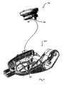
- Fig. 1 an intensifier plate 01 and a Glasverstellantrieb 02 of an outside rearview mirror of a vehicle is shown in perspective.
- the other parts of the outside rearview mirror, which are not required to understand the invention are in Fig. 1 not shown.
- the glass adjusting drive 03 is inserted from above into the intensifier plate 01 and fixed in the screw base 03 by screwing in a fastening screw.
- electrical lines are embedded in the plastic body of the amplifier plate 01. The one end of these electrical lines is contacted during assembly of the amplifier plate to a mirror base with the electrical system of the vehicle.
- the respective opposite end of the electrical leads to a arranged on the inside of the amplifier plate 01 contact element 04, which has a total of eight plug contacts 05.
- At Glasverstellantrieb 02 in turn another contact element 06 is present on the hidden shown a total of eight plug contacts 07 are provided.
- unrecognizable plug contacts 07 on the contact element 06 are provided for making electrical contact with the electrical adjustment elements provided in the glass adjustment drive 02, in particular the drive motors.
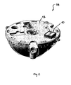
- Fig. 2 shows another, Glasverstellantrieb 08 invention
- the electromechanical adjustment of the in Fig. 3 illustrated glass assembly 09 is provided.
- a contact element 10 is attached, which serves the electrical contacting of the provided on the glass assembly 09 electrical functional elements.
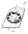
- the glass assembly 09 points to its in Fig. 3 shown back on a support plate 11, which serves the mechanical attachment of the glass assembly 09 on Glasverstellantrieb 08.
- a circular adapter ring 12 is formed, which is attached to the circular support plate 13 of the Glasverstellantriebs 08 during assembly of the rearview mirror.
- On the support plate 11 of the glass assembly 09 opposite and in Fig. 3 not shown page is required to observe the subsequent traffic mirror glass 14 is fixed, from the in Fig. 3 only the outer edge can be seen.
- the mirror glass 14 has as an optional feature on an electro-chromatic Spiegelglasabblendung.
- a mirror heating in the form of a Bankleiterfolie 21 is provided between the mirror glass 14 and the support plate 11.
- the contact element 10 For contacting the provided in the glass assembly 09 electrical functional elements, namely the mirror heating and the electrochromic Spiegelglasabblendung with the electrical system, the contact element 10 has four spring-mounted contact tongues 15, which serve as contact points.
- the contact tongues 15 electrically conductive on Flachleiterbahnenden 16, 17, 18 and 19 to the system, which together form a contact element 32 for electrical contacting of the glass assembly 09.
- the carrier plate 11 in the region of the flat conductor track ends 16, 17, 18 and 19 has a recess 20 which can be penetrated by the outer contour of the contact element 10.
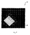
- the flat conductor track ends 16, 17, 18 and 19 are part of the track layout on a heating conductor foil 21, which in Fig. 4 and Fig. 5 is shown in more detail.
- a heating conductor foil 21 which in Fig. 4 and Fig. 5 is shown in more detail.
- a carrier foil 22 see Fig. 5 .
- Various flat conductor tracks are arranged and form Bankffleander 23, which serve as mirror heating.
- the Schuffleander 23 end up in the flat conductor ends 16 and 17, so that the mirror heating by contacting the contact points in the flat conductor ends 16 and 17 can be connected to the electrical system.
- Two further flat conductor tracks, which open into the flat conductor track ends 18 and 19, serve for electrical connection of the electrochromic mirror glass 14.
- the contact element 10 is releasably attached to the Glasverstellantrieb 08, for example, clipped, so that in embodiments that have no mirror heating and no electrochromic mirror glass, the same Glasverstellantrieb 08 can be used, in these basic versions without optional features, the contact element 10 then not on Glasverstellantrieb 08 is mounted.
- Fig. 6 the contact element 10 is shown enlarged with the contact tongues 15.
- the contact element 10 can be clipped by means of clip hooks 27 from above on the holding plate 13 of the Glasverstellantriebs 08.
- the contact tongues 15 are connected to the electrical system of the vehicle.
- a sealing ring 29 made of cellular rubber is arranged on the outer circumference of the contact element 10. This sealing ring arrives during assembly of the glass assembly 09 on Glasverstellantrieb 08 on the upper side of the Schuleiterfolie 21 in the region of the cutout 26 to the plant and protects the contact points between the flat conductor ends 16, 17, 18 and 19 with the opposite contact tongues 15 from penetrating moisture.
- a sealing gel pad 30 is provided in the intermediate space between the contact tongues 15 and the sealing ring 29.
- Fig. 7 shows a second embodiment 10a of a contact element, which differs from the first embodiment 10 in that the moisture protection is ensured by an annular sealing lip 31.
- a sealant pad 30 may optionally be omitted in the embodiment 10a.
Landscapes
- Engineering & Computer Science (AREA)
- Multimedia (AREA)
- Mechanical Engineering (AREA)
- Rear-View Mirror Devices That Are Mounted On The Exterior Of The Vehicle (AREA)
- Electrochromic Elements, Electrophoresis, Or Variable Reflection Or Absorption Elements (AREA)
Description
Die Erfindung betrifft einen Rückspiegel für ein Kraftfahrzeug nach dem Oberbegriff des Anspruchs 1.The invention relates to a rearview mirror for a motor vehicle according to the preamble of claim 1.
Gattungsgemäße Rückspiegel werden in Kraftfahrzeugen als Innenrückspiegel oder als Außenrückspiegel eingesetzt, um dem Fahrer im Spiegelglas der Glasbaugruppe die Beobachtung des nachfolgenden Verkehrs zu ermöglichen. Bei modernen Rückspiegeln, insbesondere bei modernen Außenrückspiegeln, sind eine Vielzahl von elektrischen Funktionselementen in die Rückspiegel integriert. Dabei kann es sich um Beleuchtungseinrichtungen, Antennen, Spiegelheizungen, elektrochromatisch abblendbare Spiegelgläser oder sonstige Zusatzfunktionselemente handeln. Insbesondere ist vielfach auch eine motorische Verstellung der Glasbaugruppe mittels eines Glasverstellantriebs vorgesehen, dessen Antriebsmotoren elektrisch an das Bordnetz angeschlossen werden müssen.Generic rearview mirrors are used in motor vehicles as an interior rearview mirror or as an exterior rearview mirror to allow the driver in the mirror glass of the glass assembly to observe the subsequent traffic. In modern rear-view mirrors, in particular in modern exterior rear-view mirrors, a large number of electrical functional elements are integrated into the rearview mirrors. These may be lighting devices, antennas, mirror heaters, electro-chromatically dimmable mirror glasses or other additional functional elements. In particular, a motorized adjustment of the glass assembly by means of a Glasverstellantriebs is often provided, the drive motors must be electrically connected to the electrical system.
Um die Montage des Rückspiegels bzw. der verschiedenen Bauteile des Rückspiegels zu ermöglichen, sind die Leitungen zu den verschiedenen Funktionselementen des Rückspiegels an geeigneten Stellen auftrennbar, wobei an den Leitungsenden jeweils Kontaktelemente vorgesehen sind.In order to enable the mounting of the rearview mirror or of the various components of the rearview mirror, the lines to the various functional elements of the rearview mirror can be separated at suitable locations, contact elements being provided at each of the line ends.
Bei der Montage des Rückspiegels werden diese Kontaktstellen dann miteinander kontaktiert, um die elektrische Funktionsfähigkeit der elektrischen Funktionselemente zu gewährleisten.During assembly of the rearview mirror, these contact points are then contacted with one another in order to ensure the electrical functionality of the electrical functional elements.
Die
Die
Nachteilig an den bekannten Rückspiegeln ist es, dass die Montage der Rückspiegel durch das Kontaktieren der Kontaktstellen erheblich erschwert wird. Üblicherweise sind an den verschiedenen Funktionselementen Kabelschwänze mit Steckverbindern vorgesehen, die bei der Montage des Rückspiegels von Hand montiert werden müssen. Durch diese separate Montage der Kontaktelemente wird der Montageaufwand erheblich erhöht. Eine rationelle und weitgehend vollautomatisierte Montage der Rückspiegel ist damit weitgehend ausgeschlossen.A disadvantage of the known rear-view mirrors is that the mounting of the rearview mirror is made considerably more difficult by contacting the contact points. Usually cable tails are provided with connectors on the various functional elements, which must be mounted by hand during assembly of the rearview mirror. By this separate installation of the contact elements of the assembly effort is significantly increased. A rational and largely fully automated assembly of the rearview mirror is thus largely excluded.
Nachteilig an den bekannten, mit der Fügebewegung kontaktierbaren Steckkontaktierung ist es, dass bei kleinsten Ungenauigkeiten auch nur eines Steckers die Montage unmöglich gemacht wird. Diese Gefahr ist dabei besonders groß, wenn gleichzeitig eine Vielzahl von Steckern eingesteckt werden müssen.A disadvantage of the known contact-making contactable with the joining movement is that, with the slightest inaccuracies, even a single connector makes assembly impossible. This danger is particularly great when a variety of plugs must be plugged in at the same time.
Ausgehend von diesem Stand der Technik ist es deshalb Aufgabe der vorliegenden Erfindung, einen neuen Rückspiegel vorzuschlagen, der kostengünstig montiert werden kann.Based on this prior art, it is therefore an object of the present invention to propose a new rearview mirror, which can be mounted inexpensively.
Diese Aufgabe wird durch einen Rückspiegel nach der Lehre des Anspruchs 1 gelöst.This object is achieved by a rearview mirror according to the teaching of claim 1.
Vorteilhafte Ausführungsformen der Erfindung sind Gegenstand der Unteransprüche.Advantageous embodiments of the invention are the subject of the dependent claims.
Der Rückspiegel beruht auf dem Grundgedanken, dass die Kontaktelemente an den Leitungsenden, an denen die elektrische Leitung auftrennbar ist, jeweils an einem Bauelement festgelegt sind, wobei diese Bauelemente bei der Montage des Rückspiegels miteinander gefügt werden. Die beiden Kontaktelemente sind dabei erfindungsgemäß derart an den Bauelementen angeordnet und dimensioniert, dass die einander zugeordneten Kontaktstellen der beiden Kontaktelemente durch die Fügebewegung der Bauelemente bei der Montage des Rückspiegels miteinander kontaktiert werden. Dies bedeutet mit anderen Worten, dass allein durch das mechanische Fügen der entsprechenden Bauelemente während der Spiegelmontage zugleich und ohne zusätzlichen Montageaufwand die elektrische Kontaktierung ohne weiteres hergestellt wird. Auf diese Weise kann die separate Montage der Kontaktelemente zur Herstellung der elektrischen Funktionalität eingespart werden.The rearview mirror is based on the basic idea that the contact elements at the line ends, at which the electrical line can be separated, are each fixed to a component, these components being joined together during assembly of the rearview mirror. The two contact elements are inventively arranged and dimensioned according to the invention such that the mutually associated contact points of the two contact elements are contacted by the joining movement of the components in the assembly of the rearview mirror with each other. This means, in other words, that the electrical contacting is readily produced by the mechanical joining of the corresponding components during mirror mounting at the same time and without additional installation effort. In this way, the separate mounting of the contact elements for the production of electrical functionality can be saved.
Erfindungsgemäß ist vorgesehen, dass die Kontaktstelle zumindest eines ersten Kontaktelements in der Art einer Flachleiterbahn ausgebildet ist. Diese Flachleiterbahn ist dabei auf einem geeigneten Trägerelement angeordnet, beispielsweise auf einer Leiterplatte oder einer Trägerfolie. An der Oberseite der Flachleiterbahn, insbesondere am Ende der Flachleiterbahn, ist ein nicht isolierter Bereich vorhanden, der als Kontaktstelle eines zugeordneten zweiten Kontaktelements dient. Auf diese Kontaktstelle der Flachleiterbahn wird das zugeordnete zweite Kontaktelement von oben aufgelegt und dadurch in der Kontaktfläche der elektrisch leitende Kontakt geschaffen.According to the invention, it is provided that the contact point of at least one first contact element is designed in the manner of a flat conductor track. This flat conductor track is arranged on a suitable carrier element, for example on a printed circuit board or a carrier foil. On the upper side of the flat conductor track, in particular at the end of the flat conductor track, there is a non-insulated area which serves as a contact point of an assigned second contact element. In this contact point of the flat conductor track, the associated second contact element is placed from above and thereby created in the contact surface of the electrically conductive contact.
Welche Bauteile des Rückspiegels mit erfindungsgemäßen Kontaktelementen ausgestattet sind, ist grundsätzlich beliebig. Nach einer ersten Ausführungsform der Erfindung ist ein erstes Kontaktelement am Rückspiegel selbst festgelegt. Insbesondere das Gehäuse des Rückspiegels oder die im Rückspiegel vorgesehene Verstärkerplatte eignen sich dazu.Which components of the rearview mirror are equipped with contact elements according to the invention is basically arbitrary. According to a first embodiment of the invention, a first contact element is fixed to the rearview mirror itself. In particular, the housing of the rearview mirror or the amplifier plate provided in the rearview mirror are suitable for this purpose.
Das zugeordnete zweite Kontaktelement ist gegenüberliegend an einem zur Befestigung des Rückspiegels an der Fahrzeugkarosserie vorgesehenen Spiegelfuß angeordnet. Auf diese Weise ist es dann möglich, dass allein durch die Befestigung des Rückspiegels am Spiegelfuß die Kontaktierung der im Rückspiegel vorgesehenen elektrischen Funktionselemente mit dem Bordnetz des Fahrzeuges gewährleistet wird.The associated second contact element is arranged opposite to a provided for fixing the rearview mirror to the vehicle body mirror. In this way, it is then possible that the contact of the provided in the rearview mirror electrical functional elements with the electrical system of the vehicle is ensured only by the attachment of the rearview mirror on the mirror.
Nach einer zweiten alternativen Ausführungsform ist das erste Kontaktelement wiederum am Rückspiegel selbst, insbesondere am Gehäuse oder an der Verstärkerplatte des Rückspiegels, festgelegt. Das zugeordnete zweite Kontaktelement ist bei dieser alternativen Ausführungsform am Glasverstellantrieb angeordnet, so dass durch die Montage des Glasverstellantriebs im Rückspiegel, insbesondere durch Befestigung am Gehäuse des Rückspiegels bzw. an der Verstärkerplatte des Rückspiegels, ohne weiteres die im Glasverstellantrieb befindlichen Antriebsmotoren elektrisch kontaktiert werden.According to a second alternative embodiment, the first contact element is in turn fixed on the rearview mirror itself, in particular on the housing or on the intensifier plate of the rearview mirror. The associated second contact element is arranged in this alternative embodiment of Glasverstellantrieb so that by mounting the Glasverstellantriebs in the rearview mirror, in particular by attachment to the housing of the rearview mirror or on the amplifier plate of the rearview mirror, the drive motors located in Glasverstellantrieb be contacted without further ado.
Nach einer weiteren alternativen Ausführungsform ist ein erstes Kontaktelement an der Rückseite der Glasbaugruppe festgelegt und wird mit einem zugeordneten zweiten Kontaktelement, das am Glasverstellantrieb angeordnet ist, kontaktiert.According to a further alternative embodiment, a first contact element is fixed to the rear side of the glass assembly and is contacted with an associated second contact element, which is arranged on Glasverstellantrieb.
Auf diese Weise können die in der Glasbaugruppe integrierten elektrischen Funktionselemente, vorzugsweise eine Spiegelheizung und/oder ein elektrochromatisch abblendbares Spiegelglas, mit den elektrischen Versorgungsleitungen, die durch den Glasverstellantrieb durchgeschleift sind, kontaktiert werden.In this way, the electrical functional elements integrated in the glass assembly, preferably a mirror heater and / or an electrochromically dimmable mirror glass, can be contacted with the electrical supply lines which are looped through the glass adjustment drive.
Soweit der Glasverstellantrieb dazu genutzt wird, die Glasbaugruppe mittelbar mit dem Bordnetz zu verbinden, sollte das dazu vorgesehene zweite Kontaktelement lösbar am Glasverstellantrieb befestigt sein. Auf diese Weise kann dann wahlweise in Abhängigkeit von den Sonderausstattungsmerkmalen der Glasbaugruppe das zweite Kontaktelement montiert oder weggelassen werden. Bei Ausstattungsvarianten, die keine elektrischen Funktionselemente im Bereich der Glasbaugruppe aufweisen, kann dadurch ein baugleicher Glasverstellantrieb verbaut werden, wobei das zweite Kontaktelement dann nicht am Glasverstellantrieb montiert wird. Nur bei Ausführungsvarianten mit elektrischen Funktionselementen im Bereich der Glasbaugruppe wird das zweite Kontaktelement am Glasverstellantrieb montiert, um die elektrische Kontaktierung der Glasbaugruppe zu gewährleisten.As far as the Glasverstellantrieb is used to connect the glass assembly indirectly to the electrical system, the purpose intended second contact element should be releasably secured to Glasverstellantrieb. In this way, depending on the optional features of the glass assembly, the second contact element can then optionally be mounted or omitted. For equipment variants that no having electrical functional elements in the region of the glass assembly, thereby a structurally identical Glasverstellantrieb can be installed, wherein the second contact element is then not mounted on Glasverstellantrieb. Only in embodiments with electrical functional elements in the glass assembly, the second contact element is mounted on Glasverstellantrieb to ensure electrical contact with the glass assembly.
Bei bekannten Bauformen von Glasbaugruppen ist vielfach eine Trägerplatte vorgesehen, die an der Rückseite der Glasbaugruppe angeordnet ist und form- und/oder kraftschlüssig am Glasverstellantrieb festgelegt, insbesondere aufgesteckt werden kann. Diese Trägerplatten werden üblicherweise aus Kunststoff gefertigt, der eine elektrische Isolation darstellt. Um auf einfache Weise die elektrischen Funktionselemente der Glasbaugruppe trotz der elektrisch isolierenden Trägerplatte kontaktieren zu können, sollte die Trägerplatte vorzugsweise eine Ausnehmung aufweisen. Durch diese Ausnehmung hindurch können dann die an der Glasbaugruppe vorgesehenen Kontaktstellen kontaktiert werden.In known types of glass assemblies, a support plate is often provided, which is arranged on the back of the glass assembly and positively and / or non-positively fixed to the Glasverstellantrieb, in particular can be plugged. These carrier plates are usually made of plastic, which represents an electrical insulation. In order to be able to easily contact the electrical functional elements of the glass assembly in spite of the electrically insulating carrier plate, the carrier plate should preferably have a recess. Through this recess then the provided on the glass assembly contact points can be contacted.
Diese Art der Bildung der notwendigen Kontaktstellen durch Flachleiterbahnen ist insbesondere dazu geeignet, die an Außenrückspiegeln vielfach vorgesehenen Heizleiterfolien elektrisch zu kontaktieren. Denn diese Heizleiterfolien weisen ohnehin eine Trägerfolie mit darauf angeordneten Flachleiterbahnen auf, die als Heizleiter dienen. Die Enden dieser Heizleiter können dann ohne weiteres als Kontaktstellen genutzt werden, wobei lediglich dafür zu sorgen ist, dass die Heizleiter in den entsprechenden Bereichen keine Isolation aufweisen.This type of formation of the necessary contact points by flat conductor tracks is particularly suitable for electrically contacting the heat mirror foils which are often provided on outside rearview mirrors. Because these Heizleiterfolien already have a carrier film with flat conductor tracks arranged thereon, which serve as a heating element. The ends of these heating conductors can then be readily used as contact points, it being only necessary to ensure that the heating conductors have no insulation in the corresponding areas.
Soweit die Heizleiterfolien durch die nicht isolierten Heizleiterbahnen kontaktiert werden, können völlig neuartige Fertigungstechniken zur Herstellung der Glasbaugruppe eingesetzt werden. Dies insbesondere deshalb, da die sonst üblichen Kabelschwänze an der Heizleiterfolie zur Kontaktierung der Spiegelheizung bzw. zur Kontaktierung der sonstigen an der Glasbaugruppe vorgesehenen elektrischen Funktionselemente entfallen. Dies ermöglicht es, dass die Heizleiterfolie als vorgefertigtes Halbfertigprodukt auf eine Rolle aufgespult ist und mittels einer Klebeschicht sehr rationell am Spiegelglas bzw. an der Trägerplatte befestigt werden kann.As far as the Heizleiterfolien be contacted by the non-insulated Heizleiterbahnen, completely new manufacturing techniques can be used to produce the glass assembly. This in particular because the otherwise usual cable tails on the heating conductor foil for contacting the mirror heating or for contacting the other provided on the glass assembly electrical functional elements omitted. This makes it possible that the Heizleiterfolie is wound as a prefabricated semi-finished product on a roll and can be attached very efficiently by means of an adhesive layer on the mirror glass or on the support plate.
Dies bedeutet mit anderen Worten, dass bei der Montage der Glasbaugruppe die Heizleiterfolie auf einer Rolle angeliefert wird. Zur Befestigung an der Trägerplatte wird die Schutzfolie über der Klebefläche der Heizleiterfolie abgezogen. Die Heizleiterfolie ist mit Positioniermarken vorgestanzt und ermöglicht es auf diese Weise, sehr einfach die Heizleiterfolie lagerichtig über der Trägerplatte zu positionieren. Die zunächst noch in einem Stanzgitter gehaltene Heizleiterfolie wird gegen die Trägerplatte gepresst und auf diese Weise aus dem Stanzgitter herausgetrennt. Anschließend kann auf der gegenüberliegenden Seite der Heizleiterfolie das Spiegelglas in gleicher Weise angeklebt werden. Der gesamte Montagevorgang der Glasbaugruppe kann auf diese Weise weitgehend vollautomatisch durchgeführt werden.In other words, this means that during the assembly of the glass assembly, the heating conductor foil is supplied on a roll. For attachment to the support plate, the protective film is peeled off over the adhesive surface of the heating conductor foil. The heating conductor foil is pre-punched with positioning marks and in this way makes it possible to position the heating conductor foil in the correct position over the carrier plate in a very simple manner. The first held in a stamped grid Heizleiterfolie is pressed against the support plate and separated out in this way from the stamped grid. Subsequently, the mirror glass can be glued in the same way on the opposite side of the Heizleiterfolie. The entire assembly process of the glass assembly can be carried out largely automatically in this way.
Soweit an der Glasbaugruppe neben einer Spiegelheizung auch ein elektrochromatisches Spiegelglas vorgesehen ist, sollte das Kontaktelement zur Kontaktierung des elektrochromatischen Spiegelglases ebenfalls in die Heizleiterfolie integriert sein, so dass durch geeignete Kontaktierung dieser die Kontaktstellen bildenden Flachleiterbahnen zugleich der Bordnetzkontakt zur Spiegelheizung als auch zum elektrochromatischen Spiegelglas hergestellt werden kann. Um dies zu ermöglichen, ist dabei zwischen dem elektrochromatischen Spiegelglas und der Heizleiterfolie eine weitere vorgefertigte Kontaktstelle vorzusehen, um das zur Kontaktierung des Spiegelglases an der Heizleiterfolie vorgesehene Leiterbahnelement am gegenüberliegenden Ende mit dem elektrochromatischen Spiegelglas zu verbinden.As far as the glass assembly in addition to a mirror heating and an electrochromic mirror glass is provided, the contact element for contacting the electrochromic mirror glass should also be integrated into the Heizleiterfolie, so made by suitable contacting these the contact points forming flat conductor tracks at the same time the electrical system contact for mirror heating and the electrochromic mirror glass can be. In order to make this possible, a further prefabricated contact point has to be provided between the electrochromic mirror glass and the heating conductor foil in order to connect the conductor track element provided for contacting the mirror glass to the heating conductor foil at the opposite end to the electrochromic mirror glass.
Die elektrische Kontaktierung zwischen elektrochromatischem Spiegelglas und Heizleiterfolie kann dabei wahlweise in der Art einer Lötverbindung, einer elektrisch leitenden Klebverbindung oder in der Art einer elektrisch leitenden Pressverbindung ausgebildet sein.The electrical contact between the electrochromic mirror glass and heating conductor foil can optionally be in the form of a solder joint, be formed of an electrically conductive adhesive bond or in the manner of an electrically conductive press connection.
Um die als Kontaktstelle dienende Flachleiterbahn zuverlässig elektrisch kontaktieren zu können, muss das gegenüberliegende zweite Kontaktelement eine entsprechende Konstruktion aufweisen. Dabei haben sich insbesondere federnd gelagerte Kontaktzungen zur elektrischen Kontaktierung an Flachleiterbahnen als geeignet erwiesen. Bei der Montage der beiden Bauelemente gelangen die Kontaktzungen von oben auf die Flachleiterbahn und werden aufgrund ihrer federnden Lagerung elastisch gegen die Flachleiterbahn gedrückt. Durch die elastische Vorspannung der Kontaktzungen nach der Montage ist ein elektrischer Kontakt auch bei starken Vibrationen und bei längerem Gebrauch zuverlässig gewährleistet.In order to be able to reliably contact the flat conductor track serving as a contact point, the opposite second contact element must have a corresponding construction. In this case, in particular resiliently mounted contact tongues for electrical contacting to flat conductor tracks have proven to be suitable. During assembly of the two components reach the contact tongues from above on the flat conductor track and are pressed elastically due to their resilient mounting against the flat conductor track. Due to the elastic bias of the reeds after assembly electrical contact is reliably ensured even with strong vibrations and prolonged use.
Bei der Verwendung von Flachleiterbahnen als Kontaktstellen stellt sich insbesondere bei Außenrückspiegeln das Problem des Feuchtigkeitsschutzes, um Korrosion an den Kontaktstellen zu verhindern. Bevorzugt sollte deshalb am zweiten Kontaktelement, beispielsweise einem die Kontaktzungen tragenden Adapter, ein Dichtelement zum Schutz der kontaktierten Kontaktstellen vor Feuchtigkeit vorgesehen sein. Durch Aufsetzen des zweiten Kontaktelements auf den das erste Kontaktelement bildenden Flachleiterbahnen wird dann ein geeigneter Feuchtigkeitsschutz realisiert.When using flat conductor tracks as contact points, the problem of moisture protection arises, in particular in the case of outside rear-view mirrors, in order to prevent corrosion at the contact points. Therefore, a sealing element for protecting the contacted contact points from moisture should preferably be provided on the second contact element, for example an adapter carrying the contact tongues. By placing the second contact element on the first contact element forming flat conductor tracks then a suitable moisture protection is realized.
Das Dichtelement sollte dabei bevorzugt in der Art eines geschlossenen Dichtrings ausgebildet sein, das auf diese Weise mehrere kontaktierte Kontaktstellen abdichtend umgreifen kann.The sealing element should preferably be designed in the manner of a closed sealing ring, which can embrace a plurality of contacted contact points in this way.
Konstruktiv sollte der Dichtring bevorzugt in der Art einer Zellkautschukdichtung oder in der Art einer Dichtlippe ausgebildet sein.Constructively, the sealing ring should preferably be designed in the manner of a cellular rubber seal or in the manner of a sealing lip.
Zur Verbesserung des Feuchtigkeitsschutzes kann zusätzlich zur Verwendung eines Dichtrings im Zwischenraum zwischen Dichtring und den Kontaktstellen ein Dichtgel angeordnet werden. Durch das Dichtgel wird Feuchtigkeit, die die Sperre des Dichtrings überwunden hat, von den Kontaktstellen abgehalten.To improve the moisture protection, in addition to the use of a sealing ring in the space between the sealing ring and the Contact points are arranged a sealing gel. Through the sealing gel moisture, which has overcome the barrier of the sealing ring, held away from the contact points.
Verschiedene Ausführungsformen der Erfindung sind in den Zeichnungen schematisch dargestellt und werden nachfolgend beispielhaft erläutert:Various embodiments of the invention are shown schematically in the drawings and are explained below by way of example:
Es zeigen:
- Fig. 1
- die Verstärkerplatte eines gattungsgemäßen Außenrückspie- gels mit einem daran zu befestigenden Glasverstellantrieb in perspektivischer Ansicht;
- Fig. 2
- einen Glasverstellantrieb mit daran befestigtem Kontaktele- ment in perspektivischer Ansicht;
- Fig. 3
- die am Glasverstellantrieb gemäß
Fig. 2 zu befestigende Glasbaugruppe in perspektivischer Ansicht; - Fig. 4
- die Heizleiterfolie der Glasbaugruppe gemäß
Fig. 3 in An- sicht von oben; - Fig. 5
- die Kontaktelemente zur Kontaktierung der Heizleiterfolie gemäß
Fig. 4 in vergrößerter Ansicht von oben; - Fig. 6
- das Kontaktelement zur Befestigung am Glasverstellantrieb gemäß
Fig. 2 in vergrößerter perspektivischer Ansicht; - Fig. 7
- eine zweite Ausführungsform eines Kontaktelements zur Befestigung am Glasverstellantrieb gemäß
Fig. 2 in perspek- tivischer Ansicht.
- Fig. 1
- the intensifier plate of a generic outer rearview mirror with a Glasverstellantrieb to be fastened thereto in a perspective view;
- Fig. 2
- a Glasverstellantrieb with attached contact element in perspective view;
- Fig. 3
- in accordance with the Glasverstellantrieb
Fig. 2 to be fastened glass assembly in perspective view; - Fig. 4
- the Heizleiterfolie the glass assembly according to
Fig. 3 in view from above; - Fig. 5
- the contact elements for contacting the Heizleiterfolie according to
Fig. 4 in enlarged view from above; - Fig. 6
- the contact element for attachment to Glasverstellantrieb according
Fig. 2 in an enlarged perspective view; - Fig. 7
- a second embodiment of a contact element for attachment to Glasverstellantrieb according to
Fig. 2 in perspective view.
In
Am Glasverstellantrieb 02 seinerseits ist ein weiteres Kontaktelement 06 vorhanden, an dem verdeckt dargestellt insgesamt acht Steckkontakte 07 vorgesehen sind. Die in
Bei der Montage des gattungsgemäßen Glasverstellantriebs 02 auf der Innenseite der Verstärkerplatte 01 wird der Glasverstellantrieb 02 von oben in die Verstärkerplatte 01 eingefügt. Die Kontaktelemente 04 und 06 sind dabei parallel zu der dafür erforderlichen Fügebewegung ausgerichtet, so dass die Steckkontakte 07 am Glasverstellantrieb 02 während der Fügebewegung in die Steckkontakte 05 an der Verstärkerplatte 01 eingesteckt werden. Die separate Kontaktierung des Glasverstellantriebs 02 kann auf diese Weise entfallen.When mounting the
Die Glasbaugruppe 09 weist auf ihrer in
Zur Kontaktierung der in der Glasbaugruppe 09 vorgesehenen elektrischen Funktionselemente, nämlich der Spiegelheizung und der elektrochromatischen Spiegelglasabblendung mit dem Bordnetz, weist das Kontaktelement 10 vier federnd gelagerte Kontaktzungen 15 auf, die als Kontaktstellen dienen. Bei der Montage der Glasbaugruppe 09 am Glasverstellantrieb 08 durch Aufstecken des Adapterrings 12 an der Halteplatte 13 gelangen die Kontaktzungen 15 elektrisch leitend auf Flachleiterbahnenden 16, 17, 18 und 19 zur Anlage, die gemeinsam ein Kontaktelement 32 zur elektrischen Kontaktierung der Glasbaugruppe 09 bilden. Um dies zu ermöglichen, weist die Trägerplatte 11 im Bereich der Flachleiterbahnenden 16, 17, 18 und 19 eine Ausnehmung 20 auf, die von der Außenkontur des Kontaktelements 10 durchgriffen werden kann.For contacting the provided in the
Die Flachleiterbahnenden 16, 17, 18 und 19 sind Teil des Leiterbahnlayouts auf einer Heizleiterfolie 21, die in
Bei der Befestigung der Glasbaugruppe 09 am Glasverstellantrieb 08 wird der Adapterring 12 einfach auf die Halteplatte 13 aufgesteckt, wobei die elektrische Kontaktierung der an der Glasbaugruppe 09 vorgesehenen Funktionselemente in einfacher Weise dadurch realisiert wird, dass die elastisch gelagerten Kontaktzungen 15 des Kontaktelements 10 auf den Flachleiterbahnenden 16, 17, 18 und 19 zur Anlage kommen. Das Kontaktelement 10 ist dabei lösbar am Glasverstellantrieb 08 befestigt, beispielsweise eingeclipst, so dass bei Ausführungsvarianten, die keine Spiegelheizung und kein elektrochromatisches Spiegelglas aufweisen, der gleiche Glasverstellantrieb 08 verwendet werden kann, wobei bei diesen Grundausführungsvarianten ohne Sonderausstattungsmerkmale das Kontaktelement 10 dann nicht am Glasverstellantrieb 08 montiert wird.When mounting the
In
In
Claims (17)
- A rearview mirror for a motor vehicle having a glass module for observation of the traffic behind and at least one electric function element which can be connected by at least one electric line to the vehicle electric system or other electric function elements, wherein at least one dividing point is provided in the line so that the line can be divided at this point, forming two line ends, and wherein contact elements are provided on each of the line ends, their contact points being electrically contacted during assembly of the rearview mirror, wherein the contact elements (04, 06, 10, 32) are each attached to a component (01, 02, 08, 09), wherein the components (01, 02, 08, 09) are joined together during assembly of the rearview mirror, and wherein the two contact elements (04, 06, 10, 32) are arranged on the components (01, 02, 08, 09) in such a way that the contact points (05, 07, 15, 16, 17, 18, 19) of the two contact elements (04, 06, 10, 32) assigned to one another are contacted by the joining movement of the components (01, 02, 08, 09) in assembly of the rearview mirror,
characterized in that
the contact point (16, 17, 18, 19) of at least a first contact element (32) is formed in the manner of a flat conductor which is arranged with its underside on a carrier element, in particular a carrier film (22) and which can be electrically contacted in at least one area of its top side, in particular at the end of the flat conductor, with the contact point (15) of a respective second contact element (10). - The rearview mirror according to Claim 1,
characterized in that
a first contact element is attached to the rearview mirror, in particular to the housing or to the amplifier plate of the rearview mirror, wherein a respective second contact element is attached to a mirror base provided for mounting the rearview mirror on the vehicle body. - The rearview mirror according to Claim 1 or 2,
characterized in that
a first contact element (05) is attached to the rearview mirror, in particular to the housing or to the amplifier plate (01) of the rearview mirror, wherein a respective second contact element (06) is attached to a glass adjustment drive (02). - The rearview mirror according to any one of Claims 1 through 3,
characterized in that
a first contact element (32) is attached to the rear side of the glass module (09), wherein a respective second contact element (10) is attached to the glass adjustment drive (08). - The rearview mirror according to Claim 4,
characterized in that
an electrically operated mirror heating (21) and/or an electrochromatic mirror glass (14) is provided on the glass module (09), wherein the mirror heating (21) and/or the electrochromatic mirror glass (14) can be connected directly or indirectly to the vehicle electric system via the two paired contact elements (10, 15). - The rearview mirror according to Claim 4 or 5,
characterized in that
the second contact element (10) is detachably attached to the glass adjustment drive (08) and is mounted only optionally as a function of special equipment features of the glass module (09). - The rearview mirror according to any one of Claims 4 through 6,
characterized in that
for mounting the glass module (09) on the glass adjustment drive (08), a carrier plate (11) is provided, which is arranged on the rear side of the glass module (09) and can be attached to the glass adjustment drive (08) in a form-fitting and/or frictionally engaged manner and in particular can be plug-connected, wherein the carrier plate (11) has a recess (20) through which the contact points (16, 17, 18, 19) provided on the glass module (09) can be contacted. - The rearview mirror according to Claim 7,
characterized in that
the carrier film (22) is part of a heating conductor film (21) which serves as a mirror heating. - The rearview mirror according to Claim 8,
characterized in that
the heating conductor film (21) is attached to the mirror glass (14) and/or the carrier plate (11) by means of an adhesive layer. - The rearview mirror according to Claim 8 or 9,
characterized in that
the contact points (18, 19) for contacting the electrochromatic mirror glass provided on the glass module (09) are integrated into the contact element (32) of the heating conductor film (21), wherein the electrochromatic mirror glass (14) is electrically contacted to the heating conductor film (21) at at least one additional contact point (24). - The rearview mirror according to Claim 10,
characterized in that
the electrochromatic mirror glass (14) is electrically contacted to the heating conductor film (21) by a soldered joint (24), an electrically conducting adhesive bond or an electrically conducting press connection. - The rearview mirror according to any one of Claims 7 through 11,
characterized in that
the second contact element (10) for contacting the contact point (16, 17, 18, 19) formed by a flat conductor has at least one spring-mounted contact tongue (15). - The rearview mirror according to any one of Claims 7 through 12,
characterized in that
a sealing element (29, 31) for protecting the contacted contact points (16, 17, 18, 19) from moisture is provided on the second contact element (10) for contacting the contact point (16, 17, 18, 19) formed by a flat conductor. - The rearview mirror according to Claim 13,
characterized in that
the sealing element (29, 31) surrounds multiple contact points (16, 17, 18, 19) that have been contacted, with a closed sealing ring forming a seal. - The rearview mirror according to Claim 14,
characterized in that
the sealing ring is designed in the manner of a cellular rubber gasket (29) or in the manner of a sealing lip (31). - The rearview mirror according to Claim 14,
characterized in that
the intermediate space between the sealing ring (29) and the contacted contact points (16, 17, 18, 19) is filled with an additional sealing gel (30). - The rearview mirror according to any one of Claims 1 through 16,
characterized in that
the rearview mirror is designed in the manner of an exterior mirror.
Applications Claiming Priority (1)
| Application Number | Priority Date | Filing Date | Title |
|---|---|---|---|
| DE200510020013 DE102005020013B3 (en) | 2005-04-27 | 2005-04-27 | Rearview mirror for a motor vehicle |
Publications (3)
| Publication Number | Publication Date |
|---|---|
| EP1717103A1 EP1717103A1 (en) | 2006-11-02 |
| EP1717103A8 EP1717103A8 (en) | 2006-12-27 |
| EP1717103B1 true EP1717103B1 (en) | 2012-03-28 |
Family
ID=36847873
Family Applications (1)
| Application Number | Title | Priority Date | Filing Date |
|---|---|---|---|
| EP20060008147 Active EP1717103B1 (en) | 2005-04-27 | 2006-04-20 | Rearview mirror for a motor vehicle |
Country Status (2)
| Country | Link |
|---|---|
| EP (1) | EP1717103B1 (en) |
| DE (1) | DE102005020013B3 (en) |
Families Citing this family (3)
| Publication number | Priority date | Publication date | Assignee | Title |
|---|---|---|---|---|
| EP2112022B2 (en) † | 2008-04-23 | 2014-12-10 | SMR Patents S.à.r.l. | Plastic glass mirror for vehicles |
| EP2399781B1 (en) * | 2010-06-28 | 2013-01-02 | SMR Patents S.à.r.l. | External rear view mirror with an electrical connection to an electric component housed in the external rear view mirror housing |
| EP2738043B1 (en) * | 2012-12-03 | 2015-07-22 | SMR Patents S.à.r.l. | Housing and display device |
Family Cites Families (6)
| Publication number | Priority date | Publication date | Assignee | Title |
|---|---|---|---|---|
| DE3812993A1 (en) * | 1988-04-19 | 1989-11-02 | Bernhard Mittelhaeuser | EXTERNAL REAR VIEW MIRROR FOR MOTOR VEHICLES |
| DE29620775U1 (en) * | 1996-11-29 | 1998-03-26 | Hohe Gmbh & Co Kg | Outside mirrors for a vehicle |
| DE19844269B4 (en) * | 1998-09-26 | 2005-04-07 | Reitter & Schefenacker Gmbh & Co. Kg | Adjustment device for an exterior mirror for motor vehicles |
| DE19928384A1 (en) * | 1999-06-21 | 2001-01-11 | Hohe Gmbh & Co Kg | Outside rear-view mirror with drying chamber |
| DE29915896U1 (en) * | 1999-09-10 | 1999-12-16 | Hohe Gmbh & Co Kg | Exterior rear-view mirror with electrical plug contact |
| DE10049954A1 (en) * | 2000-10-10 | 2002-05-08 | Buhler Motor Gmbh | Automotive rearview mirror |
-
2005
- 2005-04-27 DE DE200510020013 patent/DE102005020013B3/en not_active Expired - Fee Related
-
2006
- 2006-04-20 EP EP20060008147 patent/EP1717103B1/en active Active
Also Published As
| Publication number | Publication date |
|---|---|
| EP1717103A8 (en) | 2006-12-27 |
| EP1717103A1 (en) | 2006-11-02 |
| DE102005020013B3 (en) | 2006-12-07 |
Similar Documents
| Publication | Publication Date | Title |
|---|---|---|
| EP2005486B1 (en) | Electrical connecting device for flat conductors | |
| DE102004031707B4 (en) | Intelligent junction box for motor vehicles | |
| DE19841551B4 (en) | Electric rearview mirror | |
| EP1854168B1 (en) | Film antenna for a motor vehicle | |
| EP2294624B1 (en) | Junction box for photovoltaic modules | |
| DE102004025627A1 (en) | Solar module with connection element | |
| DE20215634U1 (en) | Vehicle glass | |
| EP0839687B1 (en) | External rear view mirror for vehicles | |
| EP2091113B1 (en) | Connection system for light strips or lights | |
| WO2007113030A1 (en) | Connection module for connecting a control unit or similar to a drive unit | |
| DE10157434B4 (en) | Circuit arrangement for controlling electrical devices in a vehicle | |
| DE4429983C1 (en) | Automobile electrical or electronic device | |
| EP1717103B1 (en) | Rearview mirror for a motor vehicle | |
| DE10111371A1 (en) | Flexible flat cable (FFC) for mounting conduction paths on flexible carrier material, uses integrated electrical functional component for directly contacting conduction path | |
| DE19844269A1 (en) | Adjustment device for an exterior rear-view mirror for motor vehicles | |
| DE3901307C2 (en) | Electrical connection terminal | |
| DE19819056C1 (en) | Plug-in connector for electrical ribbon cables, e.g. for automobile electronics | |
| DE102005033593B3 (en) | Contact spring in a support frame of an antenna amplifier of a vehicle | |
| DE2539379C3 (en) | Device for connecting and holding a transistor on a printed circuit board | |
| DE102007002193B4 (en) | Multi-part contacting component | |
| DE19700057C2 (en) | Data rail for the European installation bus (EIB) | |
| DE10034615C2 (en) | Method for forming a plug connector from an electrical flat cable and plug connectors created by this method, as well as supporting bodies for forming such a plug connector | |
| DE202017104896U1 (en) | Line system with at least one self-adhesive electrical line | |
| EP1777786A2 (en) | Contact element for between glass plates | |
| EP3192155A1 (en) | Electric motor having smd components and associated connection component |
Legal Events
| Date | Code | Title | Description |
|---|---|---|---|
| PUAI | Public reference made under article 153(3) epc to a published international application that has entered the european phase |
Free format text: ORIGINAL CODE: 0009012 |
|
| AK | Designated contracting states |
Kind code of ref document: A1 Designated state(s): AT BE BG CH CY CZ DE DK EE ES FI FR GB GR HU IE IS IT LI LT LU LV MC NL PL PT RO SE SI SK TR |
|
| AX | Request for extension of the european patent |
Extension state: AL BA HR MK YU |
|
| 17P | Request for examination filed |
Effective date: 20061207 |
|
| 17Q | First examination report despatched |
Effective date: 20070122 |
|
| TPAC | Observations filed by third parties |
Free format text: ORIGINAL CODE: EPIDOSNTIPA |
|
| AKX | Designation fees paid |
Designated state(s): DE FR GB |
|
| GRAP | Despatch of communication of intention to grant a patent |
Free format text: ORIGINAL CODE: EPIDOSNIGR1 |
|
| RAP1 | Party data changed (applicant data changed or rights of an application transferred) |
Owner name: MAGNA MIRRORS HOLDING GMBH |
|
| GRAS | Grant fee paid |
Free format text: ORIGINAL CODE: EPIDOSNIGR3 |
|
| GRAA | (expected) grant |
Free format text: ORIGINAL CODE: 0009210 |
|
| AK | Designated contracting states |
Kind code of ref document: B1 Designated state(s): DE FR GB |
|
| REG | Reference to a national code |
Ref country code: GB Ref legal event code: FG4D Free format text: NOT ENGLISH |
|
| REG | Reference to a national code |
Ref country code: DE Ref legal event code: R096 Ref document number: 502006011191 Country of ref document: DE Effective date: 20120524 |
|
| REG | Reference to a national code |
Ref country code: DE Ref legal event code: R097 Ref document number: 502006011191 Country of ref document: DE |
|
| PLBE | No opposition filed within time limit |
Free format text: ORIGINAL CODE: 0009261 |
|
| STAA | Information on the status of an ep patent application or granted ep patent |
Free format text: STATUS: NO OPPOSITION FILED WITHIN TIME LIMIT |
|
| 26N | No opposition filed |
Effective date: 20130103 |
|
| REG | Reference to a national code |
Ref country code: DE Ref legal event code: R082 Ref document number: 502006011191 Country of ref document: DE Representative=s name: , Ref country code: DE Ref legal event code: R082 Ref document number: 502006011191 Country of ref document: DE |
|
| REG | Reference to a national code |
Ref country code: DE Ref legal event code: R097 Ref document number: 502006011191 Country of ref document: DE Effective date: 20130103 |
|
| REG | Reference to a national code |
Ref country code: FR Ref legal event code: PLFP Year of fee payment: 11 |
|
| REG | Reference to a national code |
Ref country code: FR Ref legal event code: PLFP Year of fee payment: 12 |
|
| REG | Reference to a national code |
Ref country code: FR Ref legal event code: PLFP Year of fee payment: 13 |
|
| PGFP | Annual fee paid to national office [announced via postgrant information from national office to epo] |
Ref country code: FR Payment date: 20180420 Year of fee payment: 13 |
|
| PGFP | Annual fee paid to national office [announced via postgrant information from national office to epo] |
Ref country code: GB Payment date: 20180418 Year of fee payment: 13 |
|
| GBPC | Gb: european patent ceased through non-payment of renewal fee |
Effective date: 20190420 |
|
| PG25 | Lapsed in a contracting state [announced via postgrant information from national office to epo] |
Ref country code: GB Free format text: LAPSE BECAUSE OF NON-PAYMENT OF DUE FEES Effective date: 20190420 |
|
| PG25 | Lapsed in a contracting state [announced via postgrant information from national office to epo] |
Ref country code: FR Free format text: LAPSE BECAUSE OF NON-PAYMENT OF DUE FEES Effective date: 20190430 |
|
| PGFP | Annual fee paid to national office [announced via postgrant information from national office to epo] |
Ref country code: DE Payment date: 20230420 Year of fee payment: 18 |